EP4275912A1 - Safety element - Google Patents
Safety element Download PDFInfo
- Publication number
- EP4275912A1 EP4275912A1 EP22172504.7A EP22172504A EP4275912A1 EP 4275912 A1 EP4275912 A1 EP 4275912A1 EP 22172504 A EP22172504 A EP 22172504A EP 4275912 A1 EP4275912 A1 EP 4275912A1
- Authority
- EP
- European Patent Office
- Prior art keywords
- moth
- eye structure
- layer
- security element
- reflective layer
- Prior art date
- Legal status (The legal status is an assumption and is not a legal conclusion. Google has not performed a legal analysis and makes no representation as to the accuracy of the status listed.)
- Pending
Links
- 239000010409 thin film Substances 0.000 claims abstract description 93
- 230000000694 effects Effects 0.000 claims abstract description 76
- 239000006096 absorbing agent Substances 0.000 claims abstract description 41
- 230000003287 optical effect Effects 0.000 claims abstract description 18
- 125000006850 spacer group Chemical group 0.000 claims abstract description 9
- 230000005855 radiation Effects 0.000 claims description 7
- 238000002834 transmittance Methods 0.000 claims description 6
- 239000010410 layer Substances 0.000 description 259
- 239000000463 material Substances 0.000 description 13
- -1 polyethylene terephthalate Polymers 0.000 description 12
- PXHVJJICTQNCMI-UHFFFAOYSA-N Nickel Chemical compound [Ni] PXHVJJICTQNCMI-UHFFFAOYSA-N 0.000 description 10
- 229910052751 metal Inorganic materials 0.000 description 10
- 239000002184 metal Substances 0.000 description 10
- LIVNPJMFVYWSIS-UHFFFAOYSA-N silicon monoxide Chemical compound [Si-]#[O+] LIVNPJMFVYWSIS-UHFFFAOYSA-N 0.000 description 10
- 229910052782 aluminium Inorganic materials 0.000 description 8
- XAGFODPZIPBFFR-UHFFFAOYSA-N aluminium Chemical compound [Al] XAGFODPZIPBFFR-UHFFFAOYSA-N 0.000 description 8
- 239000004922 lacquer Substances 0.000 description 8
- VYZAMTAEIAYCRO-UHFFFAOYSA-N Chromium Chemical compound [Cr] VYZAMTAEIAYCRO-UHFFFAOYSA-N 0.000 description 6
- 239000000969 carrier Substances 0.000 description 6
- RYGMFSIKBFXOCR-UHFFFAOYSA-N Copper Chemical compound [Cu] RYGMFSIKBFXOCR-UHFFFAOYSA-N 0.000 description 5
- 239000003086 colorant Substances 0.000 description 5
- 229920001577 copolymer Polymers 0.000 description 5
- 229910052802 copper Inorganic materials 0.000 description 5
- 239000010949 copper Substances 0.000 description 5
- 239000010408 film Substances 0.000 description 5
- 238000000034 method Methods 0.000 description 5
- 229910052759 nickel Inorganic materials 0.000 description 5
- 230000000737 periodic effect Effects 0.000 description 5
- KDLHZDBZIXYQEI-UHFFFAOYSA-N Palladium Chemical compound [Pd] KDLHZDBZIXYQEI-UHFFFAOYSA-N 0.000 description 4
- 239000005083 Zinc sulfide Substances 0.000 description 4
- ADCOVFLJGNWWNZ-UHFFFAOYSA-N antimony trioxide Chemical compound O=[Sb]O[Sb]=O ADCOVFLJGNWWNZ-UHFFFAOYSA-N 0.000 description 4
- 229910052804 chromium Inorganic materials 0.000 description 4
- 239000011651 chromium Substances 0.000 description 4
- SZVJSHCCFOBDDC-UHFFFAOYSA-N ferrosoferric oxide Chemical compound O=[Fe]O[Fe]O[Fe]=O SZVJSHCCFOBDDC-UHFFFAOYSA-N 0.000 description 4
- WHJFNYXPKGDKBB-UHFFFAOYSA-N hafnium;methane Chemical compound C.[Hf] WHJFNYXPKGDKBB-UHFFFAOYSA-N 0.000 description 4
- XEEYBQQBJWHFJM-UHFFFAOYSA-N iron Substances [Fe] XEEYBQQBJWHFJM-UHFFFAOYSA-N 0.000 description 4
- 239000000395 magnesium oxide Substances 0.000 description 4
- CPLXHLVBOLITMK-UHFFFAOYSA-N magnesium oxide Inorganic materials [Mg]=O CPLXHLVBOLITMK-UHFFFAOYSA-N 0.000 description 4
- AXZKOIWUVFPNLO-UHFFFAOYSA-N magnesium;oxygen(2-) Chemical compound [O-2].[Mg+2] AXZKOIWUVFPNLO-UHFFFAOYSA-N 0.000 description 4
- 239000000178 monomer Substances 0.000 description 4
- BASFCYQUMIYNBI-UHFFFAOYSA-N platinum Chemical compound [Pt] BASFCYQUMIYNBI-UHFFFAOYSA-N 0.000 description 4
- 229920000139 polyethylene terephthalate Polymers 0.000 description 4
- 239000005020 polyethylene terephthalate Substances 0.000 description 4
- 239000011241 protective layer Substances 0.000 description 4
- ZNOKGRXACCSDPY-UHFFFAOYSA-N tungsten trioxide Chemical compound O=[W](=O)=O ZNOKGRXACCSDPY-UHFFFAOYSA-N 0.000 description 4
- 229910052984 zinc sulfide Inorganic materials 0.000 description 4
- 239000004952 Polyamide Substances 0.000 description 3
- VYPSYNLAJGMNEJ-UHFFFAOYSA-N Silicium dioxide Chemical compound O=[Si]=O VYPSYNLAJGMNEJ-UHFFFAOYSA-N 0.000 description 3
- 239000003989 dielectric material Substances 0.000 description 3
- PCHJSUWPFVWCPO-UHFFFAOYSA-N gold Chemical compound [Au] PCHJSUWPFVWCPO-UHFFFAOYSA-N 0.000 description 3
- 229910052737 gold Inorganic materials 0.000 description 3
- 239000010931 gold Substances 0.000 description 3
- 229920000620 organic polymer Polymers 0.000 description 3
- 229920002647 polyamide Polymers 0.000 description 3
- 230000001681 protective effect Effects 0.000 description 3
- VFLXBUJKRRJAKY-UHFFFAOYSA-N 13768-86-0 Chemical compound O=[Se](=O)=O VFLXBUJKRRJAKY-UHFFFAOYSA-N 0.000 description 2
- OKTJSMMVPCPJKN-UHFFFAOYSA-N Carbon Chemical compound [C] OKTJSMMVPCPJKN-UHFFFAOYSA-N 0.000 description 2
- 229920000106 Liquid crystal polymer Polymers 0.000 description 2
- 239000002033 PVDF binder Substances 0.000 description 2
- 229930040373 Paraformaldehyde Natural products 0.000 description 2
- 239000004696 Poly ether ether ketone Substances 0.000 description 2
- 239000004698 Polyethylene Substances 0.000 description 2
- 239000004642 Polyimide Substances 0.000 description 2
- 239000004734 Polyphenylene sulfide Substances 0.000 description 2
- 239000004743 Polypropylene Substances 0.000 description 2
- 229910052581 Si3N4 Inorganic materials 0.000 description 2
- BQCADISMDOOEFD-UHFFFAOYSA-N Silver Chemical compound [Ag] BQCADISMDOOEFD-UHFFFAOYSA-N 0.000 description 2
- 229910006404 SnO 2 Inorganic materials 0.000 description 2
- ATJFFYVFTNAWJD-UHFFFAOYSA-N Tin Chemical compound [Sn] ATJFFYVFTNAWJD-UHFFFAOYSA-N 0.000 description 2
- GWEVSGVZZGPLCZ-UHFFFAOYSA-N Titan oxide Chemical compound O=[Ti]=O GWEVSGVZZGPLCZ-UHFFFAOYSA-N 0.000 description 2
- XLOMVQKBTHCTTD-UHFFFAOYSA-N Zinc monoxide Chemical compound [Zn]=O XLOMVQKBTHCTTD-UHFFFAOYSA-N 0.000 description 2
- 239000000956 alloy Substances 0.000 description 2
- 229910045601 alloy Inorganic materials 0.000 description 2
- 229910052799 carbon Inorganic materials 0.000 description 2
- 229910000420 cerium oxide Inorganic materials 0.000 description 2
- 239000011248 coating agent Substances 0.000 description 2
- 238000000576 coating method Methods 0.000 description 2
- 238000004049 embossing Methods 0.000 description 2
- 229920000840 ethylene tetrafluoroethylene copolymer Polymers 0.000 description 2
- 229910001940 europium oxide Inorganic materials 0.000 description 2
- AEBZCFFCDTZXHP-UHFFFAOYSA-N europium(3+);oxygen(2-) Chemical compound [O-2].[O-2].[O-2].[Eu+3].[Eu+3] AEBZCFFCDTZXHP-UHFFFAOYSA-N 0.000 description 2
- 229910052735 hafnium Inorganic materials 0.000 description 2
- CJNBYAVZURUTKZ-UHFFFAOYSA-N hafnium(iv) oxide Chemical compound O=[Hf]=O CJNBYAVZURUTKZ-UHFFFAOYSA-N 0.000 description 2
- 229910003437 indium oxide Inorganic materials 0.000 description 2
- PJXISJQVUVHSOJ-UHFFFAOYSA-N indium(iii) oxide Chemical compound [O-2].[O-2].[O-2].[In+3].[In+3] PJXISJQVUVHSOJ-UHFFFAOYSA-N 0.000 description 2
- AMGQUBHHOARCQH-UHFFFAOYSA-N indium;oxotin Chemical compound [In].[Sn]=O AMGQUBHHOARCQH-UHFFFAOYSA-N 0.000 description 2
- UQSXHKLRYXJYBZ-UHFFFAOYSA-N iron oxide Inorganic materials [Fe]=O UQSXHKLRYXJYBZ-UHFFFAOYSA-N 0.000 description 2
- 235000013980 iron oxide Nutrition 0.000 description 2
- VBMVTYDPPZVILR-UHFFFAOYSA-N iron(2+);oxygen(2-) Chemical class [O-2].[Fe+2] VBMVTYDPPZVILR-UHFFFAOYSA-N 0.000 description 2
- LIKBJVNGSGBSGK-UHFFFAOYSA-N iron(3+);oxygen(2-) Chemical compound [O-2].[O-2].[O-2].[Fe+3].[Fe+3] LIKBJVNGSGBSGK-UHFFFAOYSA-N 0.000 description 2
- MRELNEQAGSRDBK-UHFFFAOYSA-N lanthanum(3+);oxygen(2-) Chemical compound [O-2].[O-2].[O-2].[La+3].[La+3] MRELNEQAGSRDBK-UHFFFAOYSA-N 0.000 description 2
- 238000004519 manufacturing process Methods 0.000 description 2
- 150000002739 metals Chemical class 0.000 description 2
- PLDDOISOJJCEMH-UHFFFAOYSA-N neodymium(3+);oxygen(2-) Chemical compound [O-2].[O-2].[O-2].[Nd+3].[Nd+3] PLDDOISOJJCEMH-UHFFFAOYSA-N 0.000 description 2
- BMMGVYCKOGBVEV-UHFFFAOYSA-N oxo(oxoceriooxy)cerium Chemical compound [Ce]=O.O=[Ce]=O BMMGVYCKOGBVEV-UHFFFAOYSA-N 0.000 description 2
- SIWVEOZUMHYXCS-UHFFFAOYSA-N oxo(oxoyttriooxy)yttrium Chemical compound O=[Y]O[Y]=O SIWVEOZUMHYXCS-UHFFFAOYSA-N 0.000 description 2
- MMKQUGHLEMYQSG-UHFFFAOYSA-N oxygen(2-);praseodymium(3+) Chemical compound [O-2].[O-2].[O-2].[Pr+3].[Pr+3] MMKQUGHLEMYQSG-UHFFFAOYSA-N 0.000 description 2
- BPUBBGLMJRNUCC-UHFFFAOYSA-N oxygen(2-);tantalum(5+) Chemical compound [O-2].[O-2].[O-2].[O-2].[O-2].[Ta+5].[Ta+5] BPUBBGLMJRNUCC-UHFFFAOYSA-N 0.000 description 2
- 229910052763 palladium Inorganic materials 0.000 description 2
- 229920003023 plastic Polymers 0.000 description 2
- 239000004033 plastic Substances 0.000 description 2
- 239000002985 plastic film Substances 0.000 description 2
- 229910052697 platinum Inorganic materials 0.000 description 2
- 229920002492 poly(sulfone) Polymers 0.000 description 2
- 229920006260 polyaryletherketone Polymers 0.000 description 2
- 229920001707 polybutylene terephthalate Polymers 0.000 description 2
- 229920002530 polyetherether ketone Polymers 0.000 description 2
- 229920000573 polyethylene Polymers 0.000 description 2
- 229920001721 polyimide Polymers 0.000 description 2
- 229920006324 polyoxymethylene Polymers 0.000 description 2
- 229920000069 polyphenylene sulfide Polymers 0.000 description 2
- 229920001155 polypropylene Polymers 0.000 description 2
- 229920001343 polytetrafluoroethylene Polymers 0.000 description 2
- 239000004810 polytetrafluoroethylene Substances 0.000 description 2
- 229920002620 polyvinyl fluoride Polymers 0.000 description 2
- 229920002981 polyvinylidene fluoride Polymers 0.000 description 2
- 229910003447 praseodymium oxide Inorganic materials 0.000 description 2
- FKTOIHSPIPYAPE-UHFFFAOYSA-N samarium(iii) oxide Chemical compound [O-2].[O-2].[O-2].[Sm+3].[Sm+3] FKTOIHSPIPYAPE-UHFFFAOYSA-N 0.000 description 2
- 239000011669 selenium Substances 0.000 description 2
- HBMJWWWQQXIZIP-UHFFFAOYSA-N silicon carbide Chemical compound [Si+]#[C-] HBMJWWWQQXIZIP-UHFFFAOYSA-N 0.000 description 2
- HQVNEWCFYHHQES-UHFFFAOYSA-N silicon nitride Chemical compound N12[Si]34N5[Si]62N3[Si]51N64 HQVNEWCFYHHQES-UHFFFAOYSA-N 0.000 description 2
- 229910052709 silver Inorganic materials 0.000 description 2
- 239000004332 silver Substances 0.000 description 2
- 239000011734 sodium Substances 0.000 description 2
- PBCFLUZVCVVTBY-UHFFFAOYSA-N tantalum pentoxide Inorganic materials O=[Ta](=O)O[Ta](=O)=O PBCFLUZVCVVTBY-UHFFFAOYSA-N 0.000 description 2
- 229910052718 tin Inorganic materials 0.000 description 2
- XOLBLPGZBRYERU-UHFFFAOYSA-N tin dioxide Chemical compound O=[Sn]=O XOLBLPGZBRYERU-UHFFFAOYSA-N 0.000 description 2
- 229910001887 tin oxide Inorganic materials 0.000 description 2
- 230000000007 visual effect Effects 0.000 description 2
- DRDVZXDWVBGGMH-UHFFFAOYSA-N zinc;sulfide Chemical compound [S-2].[Zn+2] DRDVZXDWVBGGMH-UHFFFAOYSA-N 0.000 description 2
- 229910018072 Al 2 O 3 Inorganic materials 0.000 description 1
- KLZUFWVZNOTSEM-UHFFFAOYSA-K Aluminium flouride Chemical compound F[Al](F)F KLZUFWVZNOTSEM-UHFFFAOYSA-K 0.000 description 1
- 229910016036 BaF 2 Inorganic materials 0.000 description 1
- ZOKXTWBITQBERF-UHFFFAOYSA-N Molybdenum Chemical compound [Mo] ZOKXTWBITQBERF-UHFFFAOYSA-N 0.000 description 1
- 239000000020 Nitrocellulose Substances 0.000 description 1
- 229920008285 Poly(ether ketone) PEK Polymers 0.000 description 1
- 229910004298 SiO 2 Inorganic materials 0.000 description 1
- RTAQQCXQSZGOHL-UHFFFAOYSA-N Titanium Chemical compound [Ti] RTAQQCXQSZGOHL-UHFFFAOYSA-N 0.000 description 1
- 238000010521 absorption reaction Methods 0.000 description 1
- 150000001252 acrylic acid derivatives Chemical class 0.000 description 1
- 239000004676 acrylonitrile butadiene styrene Substances 0.000 description 1
- 239000012790 adhesive layer Substances 0.000 description 1
- OYLGJCQECKOTOL-UHFFFAOYSA-L barium fluoride Chemical compound [F-].[F-].[Ba+2] OYLGJCQECKOTOL-UHFFFAOYSA-L 0.000 description 1
- 229910001632 barium fluoride Inorganic materials 0.000 description 1
- JUPQTSLXMOCDHR-UHFFFAOYSA-N benzene-1,4-diol;bis(4-fluorophenyl)methanone Chemical compound OC1=CC=C(O)C=C1.C1=CC(F)=CC=C1C(=O)C1=CC=C(F)C=C1 JUPQTSLXMOCDHR-UHFFFAOYSA-N 0.000 description 1
- 239000011127 biaxially oriented polypropylene Substances 0.000 description 1
- 230000005540 biological transmission Effects 0.000 description 1
- 230000015572 biosynthetic process Effects 0.000 description 1
- WUKWITHWXAAZEY-UHFFFAOYSA-L calcium difluoride Chemical compound [F-].[F-].[Ca+2] WUKWITHWXAAZEY-UHFFFAOYSA-L 0.000 description 1
- QCCDYNYSHILRDG-UHFFFAOYSA-K cerium(3+);trifluoride Chemical compound [F-].[F-].[F-].[Ce+3] QCCDYNYSHILRDG-UHFFFAOYSA-K 0.000 description 1
- 229910017052 cobalt Inorganic materials 0.000 description 1
- 239000010941 cobalt Substances 0.000 description 1
- GUTLYIVDDKVIGB-UHFFFAOYSA-N cobalt atom Chemical compound [Co] GUTLYIVDDKVIGB-UHFFFAOYSA-N 0.000 description 1
- 238000007766 curtain coating Methods 0.000 description 1
- 230000007423 decrease Effects 0.000 description 1
- 238000007598 dipping method Methods 0.000 description 1
- 238000005530 etching Methods 0.000 description 1
- 229920002457 flexible plastic Polymers 0.000 description 1
- 229910052742 iron Inorganic materials 0.000 description 1
- PQXKHYXIUOZZFA-UHFFFAOYSA-M lithium fluoride Chemical compound [Li+].[F-] PQXKHYXIUOZZFA-UHFFFAOYSA-M 0.000 description 1
- ORUIBWPALBXDOA-UHFFFAOYSA-L magnesium fluoride Chemical compound [F-].[F-].[Mg+2] ORUIBWPALBXDOA-UHFFFAOYSA-L 0.000 description 1
- 229910001512 metal fluoride Inorganic materials 0.000 description 1
- 239000000203 mixture Substances 0.000 description 1
- 229910052750 molybdenum Inorganic materials 0.000 description 1
- 239000011733 molybdenum Substances 0.000 description 1
- 229910052758 niobium Inorganic materials 0.000 description 1
- 239000010955 niobium Substances 0.000 description 1
- GUCVJGMIXFAOAE-UHFFFAOYSA-N niobium atom Chemical compound [Nb] GUCVJGMIXFAOAE-UHFFFAOYSA-N 0.000 description 1
- 229920001220 nitrocellulos Polymers 0.000 description 1
- 239000005026 oriented polypropylene Substances 0.000 description 1
- TWNQGVIAIRXVLR-UHFFFAOYSA-N oxo(oxoalumanyloxy)alumane Chemical compound O=[Al]O[Al]=O TWNQGVIAIRXVLR-UHFFFAOYSA-N 0.000 description 1
- 238000010422 painting Methods 0.000 description 1
- 239000000049 pigment Substances 0.000 description 1
- 229920006255 plastic film Polymers 0.000 description 1
- 239000004417 polycarbonate Substances 0.000 description 1
- 229920000515 polycarbonate Polymers 0.000 description 1
- 229920000728 polyester Polymers 0.000 description 1
- 239000011112 polyethylene naphthalate Substances 0.000 description 1
- 229920000642 polymer Polymers 0.000 description 1
- 239000004800 polyvinyl chloride Substances 0.000 description 1
- 229920000915 polyvinyl chloride Polymers 0.000 description 1
- 239000013615 primer Substances 0.000 description 1
- 239000002987 primer (paints) Substances 0.000 description 1
- OJIKOZJGHCVMDC-UHFFFAOYSA-K samarium(iii) fluoride Chemical compound F[Sm](F)F OJIKOZJGHCVMDC-UHFFFAOYSA-K 0.000 description 1
- 239000004065 semiconductor Substances 0.000 description 1
- 229910052710 silicon Inorganic materials 0.000 description 1
- 239000010703 silicon Substances 0.000 description 1
- 235000012239 silicon dioxide Nutrition 0.000 description 1
- 239000000377 silicon dioxide Substances 0.000 description 1
- 229910052814 silicon oxide Inorganic materials 0.000 description 1
- 238000005507 spraying Methods 0.000 description 1
- 238000004544 sputter deposition Methods 0.000 description 1
- 239000000126 substance Substances 0.000 description 1
- 229910052715 tantalum Inorganic materials 0.000 description 1
- GUVRBAGPIYLISA-UHFFFAOYSA-N tantalum atom Chemical compound [Ta] GUVRBAGPIYLISA-UHFFFAOYSA-N 0.000 description 1
- 239000011135 tin Substances 0.000 description 1
- 229910052719 titanium Inorganic materials 0.000 description 1
- 239000010936 titanium Substances 0.000 description 1
- BYMUNNMMXKDFEZ-UHFFFAOYSA-K trifluorolanthanum Chemical compound F[La](F)F BYMUNNMMXKDFEZ-UHFFFAOYSA-K 0.000 description 1
- XRADHEAKQRNYQQ-UHFFFAOYSA-K trifluoroneodymium Chemical compound F[Nd](F)F XRADHEAKQRNYQQ-UHFFFAOYSA-K 0.000 description 1
- WFKWXMTUELFFGS-UHFFFAOYSA-N tungsten Chemical compound [W] WFKWXMTUELFFGS-UHFFFAOYSA-N 0.000 description 1
- 229910052721 tungsten Inorganic materials 0.000 description 1
- 239000010937 tungsten Substances 0.000 description 1
- 229910052720 vanadium Inorganic materials 0.000 description 1
- LEONUFNNVUYDNQ-UHFFFAOYSA-N vanadium atom Chemical compound [V] LEONUFNNVUYDNQ-UHFFFAOYSA-N 0.000 description 1
- 238000007740 vapor deposition Methods 0.000 description 1
- 239000002966 varnish Substances 0.000 description 1
Images

Classifications
-
- B—PERFORMING OPERATIONS; TRANSPORTING
- B42—BOOKBINDING; ALBUMS; FILES; SPECIAL PRINTED MATTER
- B42D—BOOKS; BOOK COVERS; LOOSE LEAVES; PRINTED MATTER CHARACTERISED BY IDENTIFICATION OR SECURITY FEATURES; PRINTED MATTER OF SPECIAL FORMAT OR STYLE NOT OTHERWISE PROVIDED FOR; DEVICES FOR USE THEREWITH AND NOT OTHERWISE PROVIDED FOR; MOVABLE-STRIP WRITING OR READING APPARATUS
- B42D25/00—Information-bearing cards or sheet-like structures characterised by identification or security features; Manufacture thereof
- B42D25/30—Identification or security features, e.g. for preventing forgery
- B42D25/324—Reliefs
-
- B—PERFORMING OPERATIONS; TRANSPORTING
- B42—BOOKBINDING; ALBUMS; FILES; SPECIAL PRINTED MATTER
- B42D—BOOKS; BOOK COVERS; LOOSE LEAVES; PRINTED MATTER CHARACTERISED BY IDENTIFICATION OR SECURITY FEATURES; PRINTED MATTER OF SPECIAL FORMAT OR STYLE NOT OTHERWISE PROVIDED FOR; DEVICES FOR USE THEREWITH AND NOT OTHERWISE PROVIDED FOR; MOVABLE-STRIP WRITING OR READING APPARATUS
- B42D25/00—Information-bearing cards or sheet-like structures characterised by identification or security features; Manufacture thereof
- B42D25/30—Identification or security features, e.g. for preventing forgery
- B42D25/328—Diffraction gratings; Holograms
-
- B—PERFORMING OPERATIONS; TRANSPORTING
- B42—BOOKBINDING; ALBUMS; FILES; SPECIAL PRINTED MATTER
- B42D—BOOKS; BOOK COVERS; LOOSE LEAVES; PRINTED MATTER CHARACTERISED BY IDENTIFICATION OR SECURITY FEATURES; PRINTED MATTER OF SPECIAL FORMAT OR STYLE NOT OTHERWISE PROVIDED FOR; DEVICES FOR USE THEREWITH AND NOT OTHERWISE PROVIDED FOR; MOVABLE-STRIP WRITING OR READING APPARATUS
- B42D25/00—Information-bearing cards or sheet-like structures characterised by identification or security features; Manufacture thereof
- B42D25/30—Identification or security features, e.g. for preventing forgery
- B42D25/351—Translucent or partly translucent parts, e.g. windows
-
- B—PERFORMING OPERATIONS; TRANSPORTING
- B42—BOOKBINDING; ALBUMS; FILES; SPECIAL PRINTED MATTER
- B42D—BOOKS; BOOK COVERS; LOOSE LEAVES; PRINTED MATTER CHARACTERISED BY IDENTIFICATION OR SECURITY FEATURES; PRINTED MATTER OF SPECIAL FORMAT OR STYLE NOT OTHERWISE PROVIDED FOR; DEVICES FOR USE THEREWITH AND NOT OTHERWISE PROVIDED FOR; MOVABLE-STRIP WRITING OR READING APPARATUS
- B42D25/00—Information-bearing cards or sheet-like structures characterised by identification or security features; Manufacture thereof
- B42D25/30—Identification or security features, e.g. for preventing forgery
- B42D25/36—Identification or security features, e.g. for preventing forgery comprising special materials
- B42D25/373—Metallic materials
-
- G—PHYSICS
- G02—OPTICS
- G02B—OPTICAL ELEMENTS, SYSTEMS OR APPARATUS
- G02B5/00—Optical elements other than lenses
- G02B5/12—Reflex reflectors
- G02B5/126—Reflex reflectors including curved refracting surface
-
- G—PHYSICS
- G02—OPTICS
- G02B—OPTICAL ELEMENTS, SYSTEMS OR APPARATUS
- G02B5/00—Optical elements other than lenses
- G02B5/12—Reflex reflectors
- G02B5/136—Reflex reflectors plural reflecting elements forming part of a unitary body
Definitions
- the present invention relates to a security element with optical security features, suitable for arrangement on a flat support, comprising a moth-eye structure and a layer for producing a first color shift effect.
- Security elements are already known from the prior art which, in order to increase security against forgery, have an optical element for producing a color-shifting effect, such as a thin-film arrangement which causes a color-shifting effect by means of thin-film interference.
- a color-shifting effect such as a thin-film arrangement which causes a color-shifting effect by means of thin-film interference.
- the color shift effect can produce different typical color pairs, for example from green to blue or from magenta to green.
- a color-shifting effect from the color impression of black to any color impression is also known, and such a color-shifting effect can be achieved by using moth-eye structures with diffractive behavior.
- the company Toppan ® for example, sells a moth-eye structure under the name Asterium ® , which appears black when viewed from a steep viewing angle and colored when tilted to a flat viewing angle.
- a moth-eye structure is known, which is used as an absorber to vary the brightness of an image by Moth eye structure is arranged in the surface of the security element next to diffraction structures.
- One object of the invention is to provide a security element with optical security features, whereby a color-shifting effect is generated between atypical color pairs, thereby increasing the anti-counterfeit security of the security element.
- a security element with optical security features suitable for arrangement on a flat support comprising a moth-eye structure and a layer for producing a first color shift effect
- the security element further has a reflective layer which has reflective Layer is arranged at least in sections directly on the moth eye structure and the layer for generating a first color shift effect is arranged at least in sections overlapping with the reflective layer arranged on the moth eye structure
- the layer for generating a first color shift effect is a thin layer arrangement, comprising at least one on the reflective Layer arranged dielectric layer as a spacer layer and an absorber layer arranged on the dielectric layer.
- a particularly diverse range of color-shifting effects can be created using a thin-film arrangement.
- the thin-film arrangement causes a color-shifting effect by means of thin-film interference.
- Moth eye structures are used in the prior art due to their light-absorbing properties for anti-reflection and preventing reflections in many areas and are therefore already known in the prior art.
- Moth eye structures can be produced by various already known methods, such as embossing, etching and the like, for example on a lacquer base.
- a moth eye structure is a microstructure with a (pseudo)periodic, for example conical or sinusoidal, structure.
- the moth-eye structure can be arranged on a support in the form of a diffraction grating, with linear, circular gratings, but also cross gratings, for example, coming into consideration. Of course, it cannot be ruled out that the moth eye structure has a different structure.
- the moth-eye structure is preferably formed with the aid of an embossed lacquer layer, which essentially consists of nitrocellulose, acrylates and their copolymers, polyamides and their copolymers, polyvinyl chlorides and their copolymers.
- the moth eye structure is preferably made from a crosslinkable or crosslinked lacquer.
- the structure period is equal to or preferably smaller than the wavelength of the visible light, so that the reflection of the radiation is prevented as much as possible.
- a moth eye structure as used in the present invention, only appears dark to almost black to the viewer at a steep viewing angle, while at a flat viewing angle it has a diffractive optical appearance due to the existing periodicity effect and therefore appears colored.
- the moth eye structure in question therefore shows a color shift effect from black to colored.
- the reflective layer basically serves to make the moth eye structure "visible" in a layer structure, i.e. to increase the difference in the refractive index to other layers.
- the reflective layer also acts as an amplifier for the interference effect caused by the dielectric layer and the absorber layer of the thin-film arrangement.
- the moth eye structure according to the invention preferably has periodic structures so that the desired color shift effect can be created.
- aperiodic moth eye structures may be used if this is necessary or more advantageous for a particular effect to be achieved.
- a special security element can be produced in that the moth eye structure comprises a first area with a specific first periodicity (structure period) of the moth eyes and, in addition to this first area, a second area with a second periodicity (structure period) that is different from this first periodicity.
- the Moth-eye structure comprising the two different areas then appears dark to black in its entirety at a steep viewing angle, so the security element appears in the color of the layer to produce a first color-shifting effect, while the moth-eye structure has two or more different diffraction colors at a flat viewing angle, accordingly the two or more areas with different periodicity.
- a thin-film arrangement is used as the layer to create a first color-shifting effect.
- Color shift effect generally means that the color impression of the layer changes depending on the viewing angle. This means that in the present case the layer produces a different color impression at a steep viewing angle, i.e. at an angle of approximately 75°-90° to the surface of the security element, than at a flat viewing angle, i.e. at an angle of less than 75°, in particular less than 45°.
- the viewing angle is 90° if the security element is viewed normal to its plane and 0° if one were to look parallel to the plane of the security element.
- color-shifting effects can be achieved with already known color pairs.
- a color-shifting effect of green in a steep angle and blue in a shallow angle, or green in a steep angle and magenta in a shallow angle, or magenta in a steep angle and green in a shallow angle is known.
- a color shift effect cannot be created from blue in a steep viewing angle to green in a flat viewing angle or from magenta in a steep viewing angle to blue in a flat viewing angle. This disadvantage is intended to be overcome with the present invention.
- the layer for generating a first color shift effect is arranged at least in sections overlapping with the moth-eye structure (and the reflective layer arranged thereon).
- the layer for producing a first color shift effect can therefore be arranged both completely and only in certain sections on the reflective layer arranged on the moth eye structure.
- the reflective layer disposed on the moth eye structure is completely congruent with the layer for producing a first color shift effect.
- the effect according to the invention occurs in the overlapping area.
- the dielectric layer of the thin film array is disposed directly on the reflective layer (with the reflective layer itself disposed directly on the moth-eye structure) and the absorber layer of the thin film array is disposed directly on the dielectric layer.
- the thin film arrangement follows the microstructure of the moth eye structure, so it does not flatten the moth eye structure.
- the absorber layer of the thin-film arrangement could be arranged directly on the moth-eye structure, with the dielectric layer on the absorber layer and optionally a reflection layer for the thin-film arrangement on top of it.
- the moth-eye structure appears dark to almost black to an observer, while the thin-film arrangement appears magenta-colored, for example, because corresponding wavelengths that produce the magenta color are reflected.
- the arrangement of the thin-film arrangement on the moth-eye structure provided with the reflective layer results in a magenta-colored color impression at a steep viewing angle, which appears weaker and/or less shiny compared to the thin-film arrangement alone.
- the moth-eye structure produces a color impression in the form of a diffraction color, for example blue, due to the existing diffractive optical structure of the moth-eye structure.
- a color-shifting effect from magenta to blue is achieved, which cannot be achieved either by a moth-eye structure alone or by a thin-film arrangement alone.
- the thin-film arrangement itself shows little or no color effect at a very flat viewing angle, so that the color effect of the moth-eye structure dominates.
- the thin-film arrangement and the moth-eye structure are selected such that the thin-film arrangement shows a second color, for example green, at a medium viewing angle, which lies between a steep viewing angle and a flat viewing angle, while the moth-eye structure does not yet show any color impression at this viewing angle shows why the second color of the thin film arrangement can be seen.
- a total of three colors are visible, which cannot be achieved with a thin-film arrangement alone or with a moth-eye structure alone.
- a support according to the invention can be any support that is suitable for having a moth-eye structure applied thereto.
- This is preferably a carrier made of plastic, for example PET (polyethylene terephthalate).
- the carriers are, for example, transparent carrier films, preferably flexible plastic films, for example made of polyimide (PI), polypropylene (PP), monoaxially oriented polypropylene (MOPP), biaxially oriented polypropylene (BOPP), polyethylene (PE), polyphenylene sulfide (PPS), polyetheretherketone (PEEK ), polyether ketone (PEK), polyethyleneimide (PEI), polysulfone (PSU), polyaryl ether ketone (PAEK), polyethylene naphthalate (PEN), liquid crystalline polymers (LCP), polyester, polybutylene terephthalate (PBT), polyethylene terephthalate (PET), polyamide (PA), Polycarbonate (PC), cycloolefin cop
- the carrier can in particular be a film, but other carriers are not excluded from use.
- a thin-film arrangement usually consists of at least two sub-layers: a dielectric layer and an absorber layer.
- An additional optional reflection layer on the other side of the dielectric layer i.e. opposite the absorber layer with respect to the dielectric layer, reflects electromagnetic waves, such as light in the visible range, and thus increases the interference effect.
- the reflective layer which is arranged directly on the moth eye structure, forms this reflective layer.
- the dielectric layer serves as a spacer layer, if necessary between the reflection layer and the absorber layer.
- the color shift effect occurs when viewing the interference coating from the side of the absorber layer, i.e. when light falls through the absorber layer onto the dielectric layer.
- the invention The safety element is intended to be viewed in reflected light from the absorber side.
- dielectric materials with a refractive index less than or equal to 1.65 come into consideration, for example aluminum oxide (Al 2 O 3 ), metal fluorides, for example magnesium fluoride (MgF 2 ), aluminum fluoride (AlF 3 ), silicon oxide (SiO x ). , silicon dioxide (SiO 2 ), cerium fluoride (CeF 3 ), sodium aluminum fluorides (e.g.
- Dielectric materials with a refractive index greater than 1.65 are also suitable for the dielectric layer of the thin-film arrangement, for example zinc sulfide (ZnS), zinc oxide (ZnO), titanium dioxide (TiO 2 ), carbon (C), indium oxide (In 2 O 3 ).
- ZnS zinc sulfide
- ZnO zinc oxide
- TiO 2 titanium dioxide
- C carbon
- In 2 O 3 indium oxide
- a metallic layer can be used as the absorber layer of the thin-film arrangement, which can be, for example, a pure metal layer or a layer containing metallic clusters.
- the absorber layer preferably comprises at least one metal from the group consisting of aluminum, gold, titanium, vanadium, cobalt, tungsten, niobium, iron, molybdenum, palladium, platinum, chromium, silver, copper, nickel, tantalum, tin and/or their alloys, for example gold/palladium, copper/nickel, Copper/aluminum or chrome/nickel.
- the absorber layer can in particular be a semi-transparent metallic layer, as will be described below for the reflective layer.
- the reflective layer is applied over the entire surface or in part by known processes, such as spraying, vapor deposition, sputtering, or, for example, as printing ink using known printing processes (gravure, flexo, screen, digital printing), by painting, roller application processes, slot nozzles, dipping (rolldip coating) or curtain coating processes and the like are applied.
- known processes such as spraying, vapor deposition, sputtering, or, for example, as printing ink using known printing processes (gravure, flexo, screen, digital printing), by painting, roller application processes, slot nozzles, dipping (rolldip coating) or curtain coating processes and the like are applied.
- the metallic layer can be such that it is not or barely transparent, i.e. the transmittance is approximately less than 20%, in particular less than 10% for visible light.
- the security element according to the invention can sensibly only be viewed in reflected light because the metallic layer allows little or no light from the direction of the moth-eye structure to pass into the thin-film arrangement.
- the reflective layer comprises a semi-transparent metallic layer with a transmittance between 20 and 80% for visible light.
- the security element according to the invention can also show a color impression in transmitted light, i.e. when the observer looks at the security element from the side of the absorber layer and sees the light that penetrates through the security element, i.e. first passes through the moth-eye structure and then through the thin-film arrangement.
- the color impression that appears in transmitted light can serve as an additional security feature because it cannot be created in any other way in combination with the color shift effects in reflected light.
- the semi-transparent metallic layer can preferably consist mainly of a metal, such as chromium or aluminum, in particular a semi-transparent aluminum layer.
- the semi-transparent metallic layer can also comprise two or more different metals.
- a semi-transparent metallic layer that appears black in reflected light would also be conceivable.
- HRI layers are inherently transparent, so that in this case too, the security element according to the invention can show a color impression in transmitted light, i.e. when the observer looks at the security element from the side of the absorber layer and sees the light that penetrates through the security element, i.e. first the Moth eye structure and then the thin film arrangement passes through. Due to their transparency, security elements with an HRI layer as a reflective layer are well suited for applications in a transparent window of a data carrier or document of value.
- the section without a moth-eye structure is transparent or not in transmitted light, regardless of which side.
- the security element is designed such that the thin-film arrangement has a first color impression in a first viewing angle and that the thin-film arrangement has a second color impression that is different from the first in a second viewing angle in order to produce a color-shifting effect.
- the reflective layer of the moth-eye structure does not act as an amplifier of the color-shifting effect of the thin-film arrangement, so that the color impression of the thin-film arrangement can be well superimposed on the color impression of the moth-eye structure generated by diffraction, whereby an unusual color-shifting effect can be produced overall.
- Fig. 1 shows the longitudinal section through a moth eye structure 3 according to the invention, made from, for example, plastic or a crosslinked or crosslinkable varnish, which is worn by the carrier 2.
- a moth eye structure 3 made from, for example, plastic or a crosslinked or crosslinkable varnish, which is worn by the carrier 2.
- the Fig. 1 This is a plastic film.
- Fig. 2 shows the longitudinal section through a security element 1 according to the invention with a non-transparent metallic layer 9 as a reflective layer 6, the security element 1 comprising a carrier 2, a moth-eye structure 3 and a thin-film arrangement 4. Is looked at the security element 1 in Fig. 2 from above.
- the thin-film arrangement 4 comprises a dielectric layer (spacer layer) 5, which is arranged directly on the non-transparent metallic layer 9, and an absorber layer 8, which is arranged directly on the dielectric layer 5.
- the moth eye structure 3 acts as an absorber layer for an observer and would therefore in principle appear dark to almost black. Due to the thin-film arrangement 4 on the moth-eye structure 3, the viewer here experiences, for example, the color impression magenta; he sees the first color of the color pair of the thin-film arrangement 4. If the viewer tilts this in Fig. 2 shown security element 1 to a second, middle viewing angle 12, the color-shifting effect of the thin-film arrangement 4 occurs and the second color of the color pair of the thin-film arrangement 4 becomes visible, for example green. The moth eye structure 3 still acts as an absorber at this second viewing angle.
- the color impression changes further according to the diffraction color of the moth's eye structure 3, for example to blue. This occurs because the moth eye structure 3 diffracts light into the blue wavelength range, giving the viewer a blue color impression. Since the color impression of the second color, which is generated by the thin-film arrangement 4, is only weakly pronounced at this very flat viewing angle, it is overlaid by the blue of the moth's eye structure 3. To the viewer, the security element therefore appears blue at a flat angle. This results in at least three different color impressions depending on the viewing angle 11, 12, 13.
- the security element 1 seen here in the plane of the security element 1, next to the moth-eye structure 3, at least one section 10 without a moth-eye structure is provided, into which both the reflective layer 6 and the thin-film arrangement 4 continue and overlap with it.
- the section 10 without a moth-eye structure is flat and is formed here by the surface of the carrier 2, which is transparent. This means that even if the reflective layer is sufficiently transparent, color impressions can occur in transmitted light.
- a further reflective layer with different optical properties than the reflective layer 6 is intentionally provided on the moth-eye structure 3, so that in any case a different color impression results, for example by the further reflective layer having a different thickness as the reflective layer 6 on the moth eye structure 3; and/or by using a different material for the further reflective layer, which can lead to different absorption and consequently to different reflection and transmission.
- the reflective layer 6 on the moth-eye structure 3 does not directly adjoin the reflective layer in the section 10 without a moth-eye structure, i.e. an area without a reflective layer is provided. In the area without a reflective layer, a different color impression results than where a reflective layer is provided.
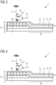
- Fig. 3 shows a longitudinal section through a security element 1 according to the invention with a semi-transparent metallic layer 14 as a reflective layer 6.
- the layer structure of the security element 1 is the same as in Fig. 2 , the color effects at the different viewing angles 11, 12, 13 also remain the same.
- the semi-transparent metallic layer 14 can preferably consist mainly of a metal, such as chromium or aluminum, in particular a semi-transparent aluminum layer.
- a color or a colored tint would be visible in the section 10 without a moth-eye structure in transmitted light, seen from the side of the absorber layer 8. Seen from the other side, a different color or a different colored tint would generally result in transmitted light because absorber layer 8 and semi-transparent metallic layer 14 generally have different properties. In reflected light when looking towards the unstructured side of the Moth-eye structure 3, i.e. from below, a weak color would be visible in the area of the moth-eye structure 3 due to reflection on the semi-transparent layer 14, and a color-shifting effect would be visible in section 10 without a moth-eye structure.
- This color-shifting effect would generally differ from the color-shifting effect when looking towards the absorber layer 8, unless the reflective layer 6, i.e. the semi-transparent metallic layer 14, were of the same nature as the absorber layer 8, i.e. had approximately the same thickness and the same material.
- HRI layers 15 are transparent per se, so that in this case too, the security element 1 according to the invention can show a color impression in transmitted light, i.e. when the viewer looks from the side of the absorber layer 8 at the security element 1 and sees the light that passes through the security element 1 penetrates, so first the moth-eye structure 3 and then the thin-film arrangement 4 passes through, see dashed arrow.
- a security element according to the Fig. 1 to 4 can also be designed in such a way that the moth eye structure 3 has at least two areas with different periodicity of the moth eyes (not shown in the figures). Such an arrangement would have the effect that the moth-eye structure 3 appears dark to black everywhere at a steep viewing angle (the security element is therefore in the color of the thin-film arrangement 4 for production a first color shift effect appears), but at a flat viewing angle a different diffraction color is achieved in each area due to the different periodicity of the areas.
- the security elements 1 can be provided with a protective lacquer layer on one or both sides in order to protect the security element 1 from external influences. That side of the security element 1 that is or is to be connected to a document of value generally does not require such a protective layer.
Abstract
Die vorliegende Erfindung betrifft ein Sicherheitselement (1) mit optischen Sicherheitsmerkmalen, geeignet für die Anordnung auf einem flächigen Träger (2), umfassend eine Mottenaugenstruktur (3) und eine Schicht zur Erzeugung eines ersten Farbkippeffekts (4), wobei das Sicherheitselement weiters eine reflektierende Schicht (6) aufweist, welche reflektierende Schicht (6) zumindest abschnittsweise direkt auf der Mottenaugenstruktur (3) angeordnet ist und die Schicht zur Erzeugung eines ersten Farbkippeffekts (4) zumindest abschnittsweise überlappend mit der auf der Mottenaugenstruktur (3) angeordneten reflektierenden Schicht (6) angeordnet ist, und wobei die Schicht zur Erzeugung eines ersten Farbkippeffekts (4) eine Dünnschichtanordnung ist, umfassend zumindest eine auf der reflektierenden Schicht (6) angeordnete dielektrische Schicht (5) als Abstandsschicht und eine auf der dielektrischen Schicht angeordnete Absorberschicht (8).The present invention relates to a security element (1) with optical security features, suitable for arrangement on a flat support (2), comprising a moth-eye structure (3) and a layer for producing a first color-shifting effect (4), the security element further comprising a reflective layer (6), which reflective layer (6) is arranged at least in sections directly on the moth-eye structure (3) and the layer for producing a first color-shifting effect (4) overlaps at least in sections with the reflective layer (6) arranged on the moth-eye structure (3). is arranged, and wherein the layer for generating a first color shift effect (4) is a thin-film arrangement, comprising at least one dielectric layer (5) arranged on the reflective layer (6) as a spacer layer and an absorber layer (8) arranged on the dielectric layer.
Description
Die vorliegende Erfindung betrifft ein Sicherheitselement mit optischen Sicherheitsmerkmalen, geeignet für die Anordnung auf einem flächigen Träger, umfassend eine Mottenaugenstruktur und eine Schicht zur Erzeugung eines ersten Farbkippeffekts.The present invention relates to a security element with optical security features, suitable for arrangement on a flat support, comprising a moth-eye structure and a layer for producing a first color shift effect.
Aus dem Stand der Technik sind bereits Sicherheitselemente bekannt, die zur Erhöhung der Fälschungssicherheit ein optisches Element zur Erzeugung eines Farbkippeffekts aufweisen, wie etwa eine Dünnschichtanordnung, die mittels Dünnschichtinterferenz einen Farbkippeffekt bewirkt. Je nach Schichtdicke kann der Farbkippeffekt unterschiedliche typische Farbenpaare erzeugen, etwa von Grün auf Blau oder von Magenta auf Grün.Security elements are already known from the prior art which, in order to increase security against forgery, have an optical element for producing a color-shifting effect, such as a thin-film arrangement which causes a color-shifting effect by means of thin-film interference. Depending on the layer thickness, the color shift effect can produce different typical color pairs, for example from green to blue or from magenta to green.
Bekannt ist beispielweise auch ein Farbkippeffekt vom Farbeindruck Schwarz auf einen beliebigen Farbeindruck, wobei ein solcher Farbkippeffekt durch die Verwendung von Mottenaugenstrukturen mit diffraktivem Verhalten erreicht werden kann. Das Unternehmen Toppan® etwa vertreibt unter dem Namen Asterium® eine Mottenaugenstruktur, welche im steilen Betrachtungswinkel schwarz und beim Kippen zu einem flachen Betrachtungswinkel farbig erscheint.For example, a color-shifting effect from the color impression of black to any color impression is also known, and such a color-shifting effect can be achieved by using moth-eye structures with diffractive behavior. The company Toppan ®, for example, sells a moth-eye structure under the name Asterium ® , which appears black when viewed from a steep viewing angle and colored when tilted to a flat viewing angle.
Aus der
Eine Aufgabe der Erfindung ist es, ein Sicherheitselement mit optischen Sicherheitsmerkmalen bereitzustellen, wobei ein Farbkippeffekt zwischen untypischen Farbenpaaren erzeugt wird, wodurch die Fälschungssicherheit des Sicherheitselements erhöht wird.One object of the invention is to provide a security element with optical security features, whereby a color-shifting effect is generated between atypical color pairs, thereby increasing the anti-counterfeit security of the security element.
Die Aufgabe der Erfindung wird durch ein Sicherheitselement mit optischen Sicherheitsmerkmalen, geeignet für die Anordnung auf einem flächigen Träger umfassend eine Mottenaugenstruktur und eine Schicht zur Erzeugung eines ersten Farbkippeffekts, gelöst, wobei erfindungsgemäß vorgesehen ist, dass das Sicherheitselement weiters eine reflektierende Schicht aufweist, welche reflektierende Schicht zumindest abschnittsweise direkt auf der Mottenaugenstruktur angeordnet ist und die Schicht zur Erzeugung eines ersten Farbkippeffekts zumindest abschnittsweise überlappend mit der auf der Mottenaugenstruktur angeordneten reflektierenden Schicht angeordnet ist, und dass die Schicht zur Erzeugung eines ersten Farbkippeffekts eine Dünnschichtanordnung ist, umfassend zumindest eine auf der reflektierenden Schicht angeordnete dielektrische Schicht als Abstandsschicht und eine auf der dielektrischen Schicht angeordnete Absorberschicht. Mit einer Dünnschichtanordnung können besonders vielfältige Farbkippeffekte erzeugt werden. Die Dünnschichtanordnung bewirkt dabei mittels Dünnschichtinterferenz einen Farbkippeffekt.The object of the invention is achieved by a security element with optical security features, suitable for arrangement on a flat support comprising a moth-eye structure and a layer for producing a first color shift effect, it being provided according to the invention that the security element further has a reflective layer which has reflective Layer is arranged at least in sections directly on the moth eye structure and the layer for generating a first color shift effect is arranged at least in sections overlapping with the reflective layer arranged on the moth eye structure, and that the layer for generating a first color shift effect is a thin layer arrangement, comprising at least one on the reflective Layer arranged dielectric layer as a spacer layer and an absorber layer arranged on the dielectric layer. A particularly diverse range of color-shifting effects can be created using a thin-film arrangement. The thin-film arrangement causes a color-shifting effect by means of thin-film interference.
Mottenaugenstrukturen werden im Stand der Technik auf Grund ihrer lichtabsorbierenden Eigenschaft zur Entspiegelung und Verhinderung von Reflexionen in vielen Bereichen verwendet und sind daher im Stand der Technik bereits bekannt. Mottenaugenstrukturen können durch unterschiedliche bereits bekannte Verfahren, wie durch Prägen, Ätzen und ähnliches, beispielsweise auf einer Lackbasis, hergestellt werden. Prinzipiell handelt es sich bei einer Mottenaugenstruktur um eine Mikrostruktur mit (pseudo)periodischer, beispielsweise konischer oder sinusförmiger, Struktur. Die Mottenaugenstruktur kann in Form eines Beugungsgitters auf einem Träger angeordnet sein, wobei hierbei beispielsweise lineare, circuläre Gitter, aber auch Kreuzgitter in Betracht kommen. Selbstverständlich ist nicht ausgeschlossen, dass die Mottenaugenstruktur eine andere Struktur aufweist.Moth eye structures are used in the prior art due to their light-absorbing properties for anti-reflection and preventing reflections in many areas and are therefore already known in the prior art. Moth eye structures can be produced by various already known methods, such as embossing, etching and the like, for example on a lacquer base. In principle, a moth eye structure is a microstructure with a (pseudo)periodic, for example conical or sinusoidal, structure. The moth-eye structure can be arranged on a support in the form of a diffraction grating, with linear, circular gratings, but also cross gratings, for example, coming into consideration. Of course, it cannot be ruled out that the moth eye structure has a different structure.
Bevorzugt wird die Mottenaugenstruktur mit Hilfe einer Prägelackschicht gebildet, welche etwa im Wesentlichen aus Nitrocellulose, Acrylaten sowie deren Copolymeren, Polyamiden sowie deren Copolymeren, Polyvinylchloriden sowie deren Copolymeren besteht. Die Mottenaugenstruktur wird dabei vorzugsweise aus einem vernetzbaren bzw. vernetzten Lack hergestellt.The moth-eye structure is preferably formed with the aid of an embossed lacquer layer, which essentially consists of nitrocellulose, acrylates and their copolymers, polyamides and their copolymers, polyvinyl chlorides and their copolymers. The moth eye structure is preferably made from a crosslinkable or crosslinked lacquer.
Um zu erreichen, dass die Mottenaugenstruktur Licht im sichtbaren Bereich absorbiert, ist vorgesehen, dass die Strukturperiode gleich der oder vorzugsweise kleiner als die Wellenlänge des sichtbaren Lichts ist, so dass die Reflexion der Strahlung möglichst verhindert wird.In order to ensure that the moth eye structure absorbs light in the visible range, it is provided that the structure period is equal to or preferably smaller than the wavelength of the visible light, so that the reflection of the radiation is prevented as much as possible.
Eine Mottenaugenstruktur, wie sie bei der gegenständlichen Erfindung verwendet wird, erscheint dem Betrachter nur in einem steilen Betrachtungswinkel dunkel bis annähernd schwarz, während sie in einem flachen Betrachtungswinkel auf Grund einer vorhandenen Periodizität einen diffraktiven optischen Effekt aufweist und dadurch farbig erscheint. Die gegenständliche Mottenaugenstruktur zeigt daher einen Farbkippeffekt von schwarz auf farbig. Die reflektierende Schicht dient grundsätzlich dazu, die Mottenaugenstruktur in einem Schichtaufbau quasi "sichtbar" zu machen, also den Unterschied im Brechungsindex zu anderen Schichten zu erhöhen. Die reflektierende Schicht wirkt zudem als Verstärker für den Interferenzeffekt, der durch die dielektrische Schicht und die Absorberschicht der Dünnschichtanordnung bewirkt wird. Bei steilem Betrachtungswinkel wird aber ein Teil des Lichts der Dünnschichtanordnung von der Mottenaugenstruktur verschluckt, wodurch die Farbe der Dünnschichtanordnung, die durch Interferenz erzeugt wird, schwächer und/oder weniger glänzend erscheint als wenn keine Mottenaugenstruktur unter der Dünnschichtanordnung vorhanden wäre. Je nach Ausbildung der Mottenaugenstruktur kann es auch zu einer Veränderung des Farbeindrucks der Dünnschichtanordnung kommen.A moth eye structure, as used in the present invention, only appears dark to almost black to the viewer at a steep viewing angle, while at a flat viewing angle it has a diffractive optical appearance due to the existing periodicity effect and therefore appears colored. The moth eye structure in question therefore shows a color shift effect from black to colored. The reflective layer basically serves to make the moth eye structure "visible" in a layer structure, i.e. to increase the difference in the refractive index to other layers. The reflective layer also acts as an amplifier for the interference effect caused by the dielectric layer and the absorber layer of the thin-film arrangement. However, at a steep viewing angle, some of the light from the thin film array is swallowed by the moth-eye structure, causing the color of the thin film array produced by interference to appear weaker and/or less shiny than if no moth-eye structure were present under the thin film array. Depending on the formation of the moth's eye structure, the color impression of the thin-film arrangement can also change.
Die erfindungsgemäße Mottenaugenstruktur weist vorzugsweise periodische Strukturen auf, damit der gewünschte Farbkippeffekt erzeugt werden kann. Es ist jedoch auch nicht ausgeschlossen, dass aperiodische Mottenaugenstrukturen herangezogen werden, sollte dies für einen bestimmten zu erreichenden Effekt erforderlich oder vorteilhafter sein.The moth eye structure according to the invention preferably has periodic structures so that the desired color shift effect can be created. However, it is also not excluded that aperiodic moth eye structures may be used if this is necessary or more advantageous for a particular effect to be achieved.
Selbstverständlich ist es auch möglich durch Variation der Strukturparameter der Mottenaugenstruktur, wie z.B. der Strukturperiode, in einer einzigen Mottenaugenstruktur unterschiedliche Beugungsfarben zu erzeugen. Beispielsweise kann ein besonderes Sicherheitselement hergestellt werden, indem die Mottenaugenstruktur einen ersten Bereich mit einer bestimmten ersten Periodizität (Strukturperiode) der Mottenaugen und neben diesem ersten Bereich einen zweiten Bereich mit einer von dieser ersten Periodizität verschiedenen zweiten Periodizität (Strukturperiode) umfasst. Die Mottenaugenstruktur umfassend die beiden unterschiedlichen Bereiche erscheint dann in einem steilen Betrachtungswinkel in ihrer Gesamtheit dennoch dunkel bis schwarz, das Sicherheitselement erscheint also in der Farbe der Schicht zur Erzeugung eines ersten Farbkippeffekts, während die Mottenaugenstruktur in einem flachen Betrachtungswinkel zwei oder mehr unterschiedliche Beugungsfarben aufweist, entsprechend den beiden oder mehreren Bereichen mit unterschiedlicher Periodizität. Dadurch kann das Sicherheitselement noch fälschungssicherer ausgestaltet werden. Dieser Effekt tritt insbesondere auch ein, wenn erster und zweiter Bereich der Mottenaugenstruktur von der gleichen Dünnschichtanordnung und der gleichen reflektierenden Schicht bedeckt sind.Of course, it is also possible to produce different diffraction colors in a single moth eye structure by varying the structural parameters of the moth eye structure, such as the structural period. For example, a special security element can be produced in that the moth eye structure comprises a first area with a specific first periodicity (structure period) of the moth eyes and, in addition to this first area, a second area with a second periodicity (structure period) that is different from this first periodicity. The Moth-eye structure comprising the two different areas then appears dark to black in its entirety at a steep viewing angle, so the security element appears in the color of the layer to produce a first color-shifting effect, while the moth-eye structure has two or more different diffraction colors at a flat viewing angle, accordingly the two or more areas with different periodicity. This allows the security element to be designed to be even more forgery-proof. This effect occurs in particular when the first and second regions of the moth eye structure are covered by the same thin-film arrangement and the same reflective layer.
Als Schicht zur Erzeugung eines ersten Farbkippeffekts wird eine Dünnschichtanordnung verwendet. Farbkippeffekt bedeutet generell, dass sich der Farbeindruck der Schicht je nach Betrachtungswinkel ändert. Dies bedeutet, dass die Schicht im gegenständlichen Fall im steilen Betrachtungswinkel, also etwa in einem Winkel von 75°-90° zur Fläche des Sicherheitselements, einen anderen Farbeindruck hervorruft als im flachen Betrachtungswinkel, also etwa einem Winkel von weniger als 75°, insbesondere weniger als 45°. Der Betrachtungswinkel beträgt 90°, wenn das Sicherheitselement normal zu seiner Ebene betrachtet wird, und 0°, wenn man parallel zur Ebene des Sicherheitselements blicken würde.A thin-film arrangement is used as the layer to create a first color-shifting effect. Color shift effect generally means that the color impression of the layer changes depending on the viewing angle. This means that in the present case the layer produces a different color impression at a steep viewing angle, i.e. at an angle of approximately 75°-90° to the surface of the security element, than at a flat viewing angle, i.e. at an angle of less than 75°, in particular less than 45°. The viewing angle is 90° if the security element is viewed normal to its plane and 0° if one were to look parallel to the plane of the security element.
Durch die Verwendung einer Dünnschichtanordnung können Farbkippeffekte mit bereits bekannten Farbpaaren erreicht werden. Bekannt ist in diesem Zusammenhang etwa ein Farbkippeffekt von Grün im steilen Winkel und Blau im flachen Winkel, oder Grün im steilen Winkel und Magenta im flachen Winkel oder Magenta im steilen Winkel und Grün im flachen Winkel. Nicht erzeugt werden kann jedoch ein Farbkippeffekt von Blau im steilen Betrachtungswinkel auf Grün im flachen Betrachtungswinkel oder von Magenta im steilen Betrachtungswinkel auf Blau im flachen Betrachtungswinkel. Dieser Nachteil soll mit der gegenständlichen Erfindung überwunden werden.By using a thin-film arrangement, color-shifting effects can be achieved with already known color pairs. In this context, a color-shifting effect of green in a steep angle and blue in a shallow angle, or green in a steep angle and magenta in a shallow angle, or magenta in a steep angle and green in a shallow angle is known. However, a color shift effect cannot be created from blue in a steep viewing angle to green in a flat viewing angle or from magenta in a steep viewing angle to blue in a flat viewing angle. This disadvantage is intended to be overcome with the present invention.
Erfindungsgemäß ist vorgesehen, dass die Schicht zur Erzeugung eines ersten Farbkippeffekts zumindest abschnittsweise überlappend mit der Mottenaugenstruktur (und der darauf angeordneten reflektierenden Schicht) angeordnet ist. Die Schicht zur Erzeugung eines ersten Farbkippeffekts kann daher sowohl vollständig als auch nur mit bestimmten Abschnitten auf der, auf der Mottenaugenstruktur angeordneten reflektierenden Schicht angeordnet sein. Vorzugsweise ist die auf der Mottenaugenstruktur angeordnete reflektierende Schicht jedoch vollständig kongruent mit der Schicht zur Erzeugung eines ersten Farbkippeffekts. Im überlappenden Bereich tritt der erfindungsgemäße Effekt auf.According to the invention, it is provided that the layer for generating a first color shift effect is arranged at least in sections overlapping with the moth-eye structure (and the reflective layer arranged thereon). The layer for producing a first color shift effect can therefore be arranged both completely and only in certain sections on the reflective layer arranged on the moth eye structure. Preferably, however, the reflective layer disposed on the moth eye structure is completely congruent with the layer for producing a first color shift effect. The effect according to the invention occurs in the overlapping area.
In der Regel ist die dielektrische Schicht der Dünnschichtanordnung direkt auf der reflektierenden Schicht angeordnet (wobei die reflektierende Schicht selbst direkt auf der Mottenaugenstruktur angeordnet ist) und die Absorberschicht der Dünnschichtanordnung direkt auf der dielektrischen Schicht angeordnet. Die Dünnschichtanordnung folgt der Mikrostruktur der Mottenaugenstruktur, ebnet also die Mottenaugenstruktur nicht ein.Typically, the dielectric layer of the thin film array is disposed directly on the reflective layer (with the reflective layer itself disposed directly on the moth-eye structure) and the absorber layer of the thin film array is disposed directly on the dielectric layer. The thin film arrangement follows the microstructure of the moth eye structure, so it does not flatten the moth eye structure.
Es wäre aber auch denkbar, dass die Absorberschicht der Dünnschichtanordnung direkt auf der Mottenaugenstruktur angeordnet ist, auf der Absorberschicht die dielektrische Schicht und darauf optional eine Reflexionsschicht für die Dünnschichtanordnung.However, it would also be conceivable for the absorber layer of the thin-film arrangement to be arranged directly on the moth-eye structure, with the dielectric layer on the absorber layer and optionally a reflection layer for the thin-film arrangement on top of it.
Durch die zumindest abschnittsweise überlappende Anordnung der Dünnschichtanordnung auf der erfindungsgemäßen Mottenaugenstruktur wird erreicht, dass zwei Farbkippeffekte erzeugt werden können. Im steilen Betrachtungswinkel erscheint die Mottenaugenstruktur einem Betrachter dunkel bis fast schwarz, während die Dünnschichtanordnung beispielsweise magentafarben wirkt, da entsprechende, die Farbe Magenta erzeugende Wellenlängen reflektiert werden. Insgesamt ergibt sich durch die Anordnung der Dünnschichtanordnung auf der, mit der reflektierenden Schicht versehenen Mottenaugenstruktur bei steilem Betrachtungswinkel ein magentafarbener Farbeindruck, der im Vergleich zur Dünnschichtanordnung allein schwächer und/oder weniger glänzend erscheint. Wenn der Betrachter das optische Sicherheitselement jedoch in einen flachen Betrachtungswinkel kippt, erzeugt die Mottenaugenstruktur auf Grund der vorhandenen diffraktiven optischen Struktur der Mottenaugenstruktur einen Farbeindruck in Form einer Beugungsfarbe, z.B. Blau. Auf diese Weise wird ein Farbkippeffekt von Magenta auf Blau erreicht, der weder durch eine Mottenaugenstruktur alleine noch durch eine Dünnschichtanordnung alleine erzielt werden kann. Die Dünnschichtanordnung selbst zeigt bei sehr flachem Betrachtungswinkel keinen oder nur eine geringen Farbeffekt, sodass der Farbeffekt der Mottenaugenstruktur dominiert.Due to the at least partially overlapping arrangement of the thin-film arrangement on the inventive Moth eye structure is achieved that two color shifting effects can be created. At a steep viewing angle, the moth-eye structure appears dark to almost black to an observer, while the thin-film arrangement appears magenta-colored, for example, because corresponding wavelengths that produce the magenta color are reflected. Overall, the arrangement of the thin-film arrangement on the moth-eye structure provided with the reflective layer results in a magenta-colored color impression at a steep viewing angle, which appears weaker and/or less shiny compared to the thin-film arrangement alone. However, if the viewer tilts the optical security element into a flat viewing angle, the moth-eye structure produces a color impression in the form of a diffraction color, for example blue, due to the existing diffractive optical structure of the moth-eye structure. In this way, a color-shifting effect from magenta to blue is achieved, which cannot be achieved either by a moth-eye structure alone or by a thin-film arrangement alone. The thin-film arrangement itself shows little or no color effect at a very flat viewing angle, so that the color effect of the moth-eye structure dominates.
Denkbar ist auch, dass die Dünnschichtanordnung und die Mottenaugenstruktur so ausgewählt sind, dass die Dünnschichtanordnung in einem mittleren Betrachtungswinkel, der zwischen einem steilen Betrachtungswinkel und einem flachen Betrachtungswinkel liegt, eine zweite Farbe zeigt, z.B. Grün, während die Mottenaugenstruktur bei diesem Betrachtungswinkel noch keinen Farbeindruck zeigt, weshalb die zweite Farbe der Dünnschichtanordnung zu sehen ist. Damit sind in Abhängigkeit vom Betrachtungswinkel insgesamt schon drei Farben sichtbar, die mit einer Dünnschichtanordnung allein oder mit einer Mottenaugenstruktur allein nicht erzielt werden können.It is also conceivable that the thin-film arrangement and the moth-eye structure are selected such that the thin-film arrangement shows a second color, for example green, at a medium viewing angle, which lies between a steep viewing angle and a flat viewing angle, while the moth-eye structure does not yet show any color impression at this viewing angle shows why the second color of the thin film arrangement can be seen. This means that, depending on the viewing angle, a total of three colors are visible, which cannot be achieved with a thin-film arrangement alone or with a moth-eye structure alone.
In einer bevorzugten Ausführungsform der Erfindung ist vorgesehen, dass das Sicherheitselement weiters einen flächigen Träger umfasst. Die Mottenaugenstruktur und die Dünnschichtanordnung sind in der Regel flächige Schichten, sie bilden ein flächiges Sicherheitselement. Sie werden aus Gründen der Stabilität in der Regel auf einem flächigen Träger angeordnet. Die Schichten des Sicherheitselements, nämlich die Mottenaugenstruktur und die Dünnschichtanordnung, sind bei Vorhandensein eines Trägers auf der gleichen Seite des Trägers angeordnet. Dabei ist beispielsweise die nicht strukturierte Seite der Mottenaugenstruktur mit dem Träger verbunden, z.B. indem die Mottenaugenstruktur in die Oberfläche des Trägers oder in eine Lackschicht eingeprägt ist, die sich auf dem Träger befindet.In a preferred embodiment of the invention it is provided that the security element further comprises a flat carrier. The moth-eye structure and the thin-film arrangement are generally flat layers; they form a flat security element. For reasons of stability, they are usually arranged on a flat support. The layers of the security element, namely the moth-eye structure and the thin-film arrangement, are arranged on the same side of the carrier when a carrier is present. For example, the non-structured side of the moth-eye structure is connected to the carrier, for example by embossing the moth-eye structure into the surface of the carrier or into a lacquer layer that is located on the carrier.
Ein erfindungsgemäßer Träger kann jeder Träger sein, der dazu geeignet ist, dass eine Mottenaugenstruktur auf ihm aufgebracht wird. Vorzugsweise handelt es sich hierbei um einen Träger aus Kunststoff, beispielsweise PET (Polyethylenterephthalat). Selbstverständlich wird die Verwendung anderer geeigneter Materialien nicht ausgeschlossen. Als Träger kommen beispielsweise transparente Trägerfolien, vorzugsweise flexible Kunststofffolien, beispielsweise aus Polyimid (PI), Polypropylen (PP), monoaxial orientiertem Polypropylen (MOPP), biaxial orientierten Polypropylen (BOPP), Polyethylen (PE), Polyphenylensulfid (PPS), Polyetheretherketon (PEEK), Polyetherketon (PEK), Polyethylenimid (PEI), Polysulfon (PSU), Polyaryletherketon (PAEK), Polyethylennaphthalat (PEN), flüssigkristalline Polymere (LCP), Polyester, Polybutylenterephthalat (PBT) , Polyethylenterephthalat (PET), Polyamid (PA), Polycarbonat (PC), Cycloolefincopolymere (COC), Polyoximethylen (POM), Acrylnitril-butadien-styrol (ABS), Polyvinylchlorid (PVC) Ethylentetrafluorethylen (ETFE), Polytetrafluorethylen (PTFE), Polyvinylfluorid (PVF), Polyvinylidenfluorid (PVDF) und Ethylen-Tetrafluorethylen-Hexafluorpropylen-Fluorterpolymer (EFEP) und/oder Mischungen und/oder Co-Polymere dieser Materialien in Frage. Die Träger bzw. Trägerfolien können transparent, transluzent, semiopak oder opak sein.A support according to the invention can be any support that is suitable for having a moth-eye structure applied thereto. This is preferably a carrier made of plastic, for example PET (polyethylene terephthalate). Of course, the use of other suitable materials is not excluded. The carriers are, for example, transparent carrier films, preferably flexible plastic films, for example made of polyimide (PI), polypropylene (PP), monoaxially oriented polypropylene (MOPP), biaxially oriented polypropylene (BOPP), polyethylene (PE), polyphenylene sulfide (PPS), polyetheretherketone (PEEK ), polyether ketone (PEK), polyethyleneimide (PEI), polysulfone (PSU), polyaryl ether ketone (PAEK), polyethylene naphthalate (PEN), liquid crystalline polymers (LCP), polyester, polybutylene terephthalate (PBT), polyethylene terephthalate (PET), polyamide (PA), Polycarbonate (PC), cycloolefin copolymers (COC), polyoxymethylene (POM), acrylonitrile butadiene styrene (ABS), polyvinyl chloride (PVC) ethylenetetrafluoroethylene (ETFE), polytetrafluoroethylene (PTFE), polyvinyl fluoride (PVF), polyvinylidene fluoride (PVDF) and Ethylene-tetrafluoroethylene-hexafluoropropylene fluoroterpolymer (EFEP) and/or mixtures and/or co-polymers of these materials in question. The carriers or carrier films can be transparent, translucent, semi-opaque or opaque.
Der Träger kann insbesondere eine Folie sein, andere Träger sind jedoch von der Verwendung nicht ausgeschlossen.The carrier can in particular be a film, but other carriers are not excluded from use.
Vorzugsweise ist vorgesehen, dass das Sicherheitselement durch Schutzschichten auf einer oder auf beiden Seiten geschützt wird, z.B. mittels Schutzlackschichten oder zusätzlicher Folien. So kann etwa eine auf der Oberfläche des Sicherheitselements liegende Mottenaugenstruktur oder eine Schicht zur Erzeugung eines Farbkippeffekts mit einer Schutzschicht versehen sein. Und/oder es kann etwa auf dem Träger eine Schutzschicht angeordnet sein, um den Träger zu schützen.It is preferably provided that the security element is protected by protective layers on one or both sides, for example by means of protective lacquer layers or additional films. For example, a moth-eye structure lying on the surface of the security element or a layer to create a color-shifting effect can be provided with a protective layer. And/or a protective layer can be arranged on the carrier in order to protect the carrier.
Eine Dünnschichtanordnung besteht in der Regel aus zumindest zwei Teilschichten: einer dielektrischen Schicht und einer Absorberschicht. Eine zusätzliche optionale Reflexionsschicht auf der anderen Seite der dielektrischen Schicht, also der Absorberschicht bezüglich der dielektrischen Schicht gegenüberliegend, reflektiert elektromagnetische Wellen, etwa Licht im sichtbaren Bereich, und verstärkt somit den Interferenzeffekt. Bei der erfindungsgemäßen Dünnschichtanordnung bildet die reflektierende Schicht, die direkt auf der Mottenaugenstruktur angeordnet ist, diese Reflexionsschicht. Die dielektrische Schicht dient als Abstandsschicht, gegebenenfalls zwischen Reflexionsschicht und Absorberschicht. Der Farbkippeffekt tritt bei Betrachtung der Interferenzbeschichtung von der Seite der Absorberschicht auf, wenn also Licht durch die Absorberschicht auf die dielektrische Schicht fällt. Das erfindungsgemäße Sicherheitselement ist dafür gedacht im Auflicht von der Absorberseite her betrachtet zu werden.A thin-film arrangement usually consists of at least two sub-layers: a dielectric layer and an absorber layer. An additional optional reflection layer on the other side of the dielectric layer, i.e. opposite the absorber layer with respect to the dielectric layer, reflects electromagnetic waves, such as light in the visible range, and thus increases the interference effect. In the thin film arrangement according to the invention, the reflective layer, which is arranged directly on the moth eye structure, forms this reflective layer. The dielectric layer serves as a spacer layer, if necessary between the reflection layer and the absorber layer. The color shift effect occurs when viewing the interference coating from the side of the absorber layer, i.e. when light falls through the absorber layer onto the dielectric layer. The invention The safety element is intended to be viewed in reflected light from the absorber side.
Für die dielektrische Schicht der Dünnschichtanordnung kommen dielektrische Materialien mit einem Brechungsindex kleiner oder gleich 1,65 in Frage, z.B. Aluminiumoxid (Al2O3), Metallfluoride, beispielsweise Magnesiumfluorid (MgF2), Aluminiumfluorid (AlF3), Siliziumoxid (SiOx), Siliziumdioxid (SiO2),Cerfluorid (CeF3), Natrium-Aluminium-Fluoride (z.B. Na3AlF6 oder Na5Al3F14), Neodymfluorid (NdF3), Lanthanfluorid (LaF3), Samariumfluorid (SmF3), Bariumfluorid (BaF2), Calciumfluorid (CaF2), Lithiumfluorid (LiF), niedrigbrechende organische Monomere und/oder niedrigbrechende organische Polymere.For the dielectric layer of the thin-film arrangement, dielectric materials with a refractive index less than or equal to 1.65 come into consideration, for example aluminum oxide (Al 2 O 3 ), metal fluorides, for example magnesium fluoride (MgF 2 ), aluminum fluoride (AlF 3 ), silicon oxide (SiO x ). , silicon dioxide (SiO 2 ), cerium fluoride (CeF 3 ), sodium aluminum fluorides (e.g. Na 3 AlF 6 or Na 5 Al 3 F 14 ), neodymium fluoride (NdF 3 ), lanthanum fluoride (LaF 3 ), samarium fluoride (SmF 3 ) , barium fluoride (BaF 2 ), calcium fluoride (CaF 2 ), lithium fluoride (LiF), low-refractive index organic monomers and/or low-refractive index organic polymers.
Für die dielektrische Schicht der Dünnschichtanordnung kommen aber auch dielektrische Materialien mit einem Brechungsindex größer 1,65 in Frage, z.B. Zinksulfid (ZnS), Zinkoxid (ZnO), Titandioxid (TiO2), Kohlenstoff (C), Indiumoxid (In2O3), Indium-Zinn-Oxid (ITO), Tantalpentoxid (Ta2O5), Ceroxid (CeO2), Yttriumoxid (Y2O3), Europiumoxid (Eu2O3), Eisenoxide wie zum Beispiel Eisen (II,III) oxid (Fe3O4) und Eisen (III) oxid (Fe2O3), Hafniumnitrid (HfN), Hafniumcarbid (HfC), Hafniumoxid (HfO2), Lanthanoxid (La2O3), Magnesiumoxid (MgO), Neodymoxid (Nd2O3), Praseodymoxid (Pr6O11), Samariumoxid (Sm2O3), Antimontrioxid (Sb2O3), Siliziumcarbid (SiC), Siliziumnitrid (Si3N4), Siliziummonoxid (SiO), Selentrioxid (Se2O3), Zinnoxid (SnO2), Wolframtrioxid (WO3), hochbrechende organische Monomere und/oder hochbrechende organische Polymere.Dielectric materials with a refractive index greater than 1.65 are also suitable for the dielectric layer of the thin-film arrangement, for example zinc sulfide (ZnS), zinc oxide (ZnO), titanium dioxide (TiO 2 ), carbon (C), indium oxide (In 2 O 3 ). , indium tin oxide (ITO), tantalum pentoxide (Ta 2 O 5 ), cerium oxide (CeO 2 ), yttrium oxide (Y 2 O 3 ), europium oxide (Eu 2 O 3 ), iron oxides such as iron (II,III) oxide (Fe 3 O 4 ) and iron (III) oxide (Fe 2 O 3 ), hafnium nitride (HfN), hafnium carbide (HfC), hafnium oxide (HfO 2 ), lanthanum oxide (La 2 O 3 ), magnesium oxide (MgO), neodymium oxide (Nd 2 O 3 ), praseodymium oxide (Pr 6 O 11 ), samarium oxide (Sm 2 O 3 ), antimony trioxide (Sb 2 O 3 ), silicon carbide (SiC), silicon nitride (Si 3 N 4 ), silicon monoxide (SiO), selenium trioxide (Se 2 O 3 ), tin oxide (SnO 2 ), tungsten trioxide (WO 3 ), high-index organic monomers and/or high-index organic polymers.
Als Absorberschicht der Dünnschichtanordnung kann eine metallische Schicht eingesetzt werden, wobei es sich beispielsweise um eine reine Metallschicht handeln kann oder um eine metallische Cluster enthaltende Schicht. Vorzugsweise umfasst die Absorberschicht zumindest ein Metall der Gruppe bestehend aus Aluminium, Gold, Titan, Vanadium, Kobalt, Wolfram, Niob, Eisen, Molybdän, Palladium, Platin, Chrom, Silber, Kupfer, Nickel, Tantal, Zinn und/oder deren Legierungen, beispielsweise Gold/Palladium, Kupfer/Nickel, Kupfer/Aluminium oder Chrom/Nickel. Die Absorberschicht kann insbesondere eine semitransparente metallische Schicht sein, wie dies im Folgenden für die reflektierende Schicht beschrieben wird.A metallic layer can be used as the absorber layer of the thin-film arrangement, which can be, for example, a pure metal layer or a layer containing metallic clusters. The absorber layer preferably comprises at least one metal from the group consisting of aluminum, gold, titanium, vanadium, cobalt, tungsten, niobium, iron, molybdenum, palladium, platinum, chromium, silver, copper, nickel, tantalum, tin and/or their alloys, for example gold/palladium, copper/nickel, Copper/aluminum or chrome/nickel. The absorber layer can in particular be a semi-transparent metallic layer, as will be described below for the reflective layer.
Als reflektierende Schicht, die zusätzlich als Reflexionsschicht der Dünnschichtanordnung dient, kann eine metallische Schicht eingesetzt werden, welche vorzugsweise zumindest ein Metall ausgewählt aus der Gruppe bestehend aus Aluminium, Gold, Chrom, Silber, Kupfer, Zinn, Platin, Nickel und deren Legierungen, beispielsweise Nickel/Chrom oder Kupfer/Aluminium. Ebenfalls ist es denkbar, dass die reflektierende Schicht einen Halbleiter, wie etwa Silicium, enthält. Schließlich ist es auch denkbar, dass die reflektierende Schicht durch Auftragen einer Druckfarbe mit metallischen Pigmenten, vorzugweise aus einem Metall aus der zuvor erwähnten Gruppe, hergestellt wird. Die reflektierende Schicht wird vollflächig oder partiell durch bekannte Verfahren, wie Sprühen, Bedampfen, Sputtern, oder beispielsweise als Druckfarbe durch bekannte Druckverfahren (Tief-, Flexo-, Sieb-, Digitaldruck), durch Lackieren, Walzenauftragsverfahren, Schlitzdüsen-, Tauch-(rolldip coating) oder Vorhangauftragsverfahren (curtain coating) und dergleichen aufgebracht.A metallic layer can be used as the reflective layer, which additionally serves as the reflection layer of the thin-film arrangement, which preferably has at least one metal selected from the group consisting of aluminum, gold, chromium, silver, copper, tin, platinum, nickel and their alloys, for example Nickel/chrome or copper/aluminum. It is also conceivable that the reflective layer contains a semiconductor, such as silicon. Finally, it is also conceivable that the reflective layer is produced by applying a printing ink with metallic pigments, preferably made of a metal from the group mentioned above. The reflective layer is applied over the entire surface or in part by known processes, such as spraying, vapor deposition, sputtering, or, for example, as printing ink using known printing processes (gravure, flexo, screen, digital printing), by painting, roller application processes, slot nozzles, dipping (rolldip coating) or curtain coating processes and the like are applied.
Es ist denkbar, dass die metallische Schicht auf der Mottenaugenstruktur in unterschiedlichen Flächenbereichen unterschiedliche Eigenschaften aufweist, z.B. in unterschiedlichen Flächenbereichen unterschiedliche Metalle als Hauptbestandteil aufweist, und/oder unterschiedlich transparent ist, und/oder unterschiedliche mittlere (über mehrere Strukturperioden gemittelte) Dicken aufweist.It is conceivable that the metallic layer on the moth-eye structure has different properties in different surface areas, for example has different metals as the main component in different surface areas, and/or different is transparent, and/or has different average thicknesses (averaged over several structural periods).
Die metallische Schicht kann so beschaffen sein, dass diese nicht oder kaum transparent ist, der Transmissionsgrad also etwa kleiner 20%, insbesondere kleiner 10% für sichtbares Licht ist. In diesem Fall kann das erfindungsgemäße Sicherheitselement sinnvoller Weise nur im Auflicht betrachtet werden, weil die metallische Schicht kein oder kaum Licht aus Richtung der Mottenaugenstruktur in die Dünnschichtanordnung durchlässt.The metallic layer can be such that it is not or barely transparent, i.e. the transmittance is approximately less than 20%, in particular less than 10% for visible light. In this case, the security element according to the invention can sensibly only be viewed in reflected light because the metallic layer allows little or no light from the direction of the moth-eye structure to pass into the thin-film arrangement.
In einer Ausführungsform der Erfindung ist vorgesehen, dass die reflektierende Schicht eine semitransparente metallische Schicht mit einem Transmissionsgrad zwischen 20 und 80% für sichtbares Licht umfasst. In diesem Fall kann das erfindungsgemäße Sicherheitselement auch im Durchlicht einen Farbeindruck zeigen, wenn also der Betrachter von der Seite der Absorberschicht auf das Sicherheitselement blickt und das Licht sieht, dass durch das Sicherheitselement dringt, also zuerst die Mottenaugenstruktur und dann die Dünnschichtanordnung durchläuft. Der Farbeindruck, der sich im Durchlicht einstellt, kann als zusätzliches Sicherheitsmerkmal dienen, weil er in Kombination mit den Farbkippeffekten im Auflicht nicht anders hervorgerufen werden kann.In one embodiment of the invention it is provided that the reflective layer comprises a semi-transparent metallic layer with a transmittance between 20 and 80% for visible light. In this case, the security element according to the invention can also show a color impression in transmitted light, i.e. when the observer looks at the security element from the side of the absorber layer and sees the light that penetrates through the security element, i.e. first passes through the moth-eye structure and then through the thin-film arrangement. The color impression that appears in transmitted light can serve as an additional security feature because it cannot be created in any other way in combination with the color shift effects in reflected light.
Die semitransparente metallische Schicht kann vorzugsweise hauptsächlich aus einem Metall bestehen, etwa Chrom oder Aluminium, insbesondere eine semitransparente Aluminiumschicht sein. Die semitransparente metallische Schicht kann aber auch zwei oder mehr verschiedene Metalle umfassen.The semi-transparent metallic layer can preferably consist mainly of a metal, such as chromium or aluminum, in particular a semi-transparent aluminum layer. However, the semi-transparent metallic layer can also comprise two or more different metals.
Denkbar wäre auch eine semitransparente metallische Schicht, die im Auflicht schwarz erscheint.A semi-transparent metallic layer that appears black in reflected light would also be conceivable.
Sicherheitselemente mit einer semitransparenten Metallschicht als reflektierende Schicht sind aufgrund ihrer Transparenz gut für Anwendungen in einem transparenten Fenster eines Datenträgers oder Wertdokuments geeignet.Due to their transparency, security elements with a semi-transparent metal layer as a reflective layer are well suited for applications in a transparent window of a data carrier or document of value.
Als reflektierende Schicht können auch sogenannte HRI-Schichten (High Refractive Index Schichten) verwendet werden, die ein Material mit einem Brechungsindex größer 1,5 umfassen. Solche HRI-Schichten weisen beispielsweise dielektrische Materialien mit einem Brechungsindex von größer oder gleich 1,65 auf, z.B Zinksulfid (ZnS), Zinkoxid (ZnO), Titandioxid (TiO2), Kohlenstoff (C), Indiumoxid (In2O3), Indium-Zinn-Oxid (ITO), Tantalpentoxid (Ta2O5), Ceroxid (CeO2), Yttriumoxid (Y2O3), Europiumoxid (Eu2O3), Eisenoxide wie zum Beispiel Eisen (II,III) oxid (Fe3O4) und Eisen (III) oxid (Fe2O3), Hafniumnitrid (HfN), Hafniumcarbid (HfC), Hafniumoxid (HfO2), Lanthanoxid (La2O3), Magnesiumoxid (MgO), Neodymoxid (Nd2O3), Praseodymoxid (Pr6O11), Samariumoxid (Sm2O3), Antimontrioxid (Sb2O3), Siliziumcarbid (SiC), Siliziumnitrid (Si3N4), Siliziummonoxid (SiO), Selentrioxid (Se2O3), Zinnoxid (SnO2), Wolframtrioxid (WO3), hochbrechende organische Monomere und/oder hochbrechende organische Polymere. Diese Materialien können entweder aufgedampft oder aufgedruckt (vor allem die Monomere und Polymere) werden.So-called HRI layers (high refractive index layers), which comprise a material with a refractive index greater than 1.5, can also be used as a reflective layer. Such HRI layers have, for example, dielectric materials with a refractive index of greater than or equal to 1.65, for example zinc sulfide (ZnS), zinc oxide (ZnO), titanium dioxide (TiO 2 ), carbon (C), indium oxide (In 2 O 3 ). Indium tin oxide (ITO), tantalum pentoxide (Ta 2 O 5 ), cerium oxide (CeO 2 ), yttrium oxide (Y 2 O 3 ), europium oxide (Eu 2 O 3 ), iron oxides such as iron (II,III) oxide (Fe 3 O 4 ) and iron (III) oxide (Fe 2 O 3 ), hafnium nitride (HfN), hafnium carbide (HfC), hafnium oxide (HfO 2 ), lanthanum oxide (La 2 O 3 ), magnesium oxide (MgO), neodymium oxide ( Nd 2 O 3 ), praseodymium oxide (Pr 6 O 11 ), samarium oxide (Sm 2 O 3 ), antimony trioxide (Sb 2 O 3 ), silicon carbide (SiC), silicon nitride (Si 3 N 4 ), silicon monoxide (SiO), selenium trioxide ( Se 2 O 3 ), tin oxide (SnO 2 ), tungsten trioxide (WO 3 ), high-index organic monomers and/or high-index organic polymers. These materials can be either vapor deposited or printed (especially the monomers and polymers).
HRI-Schichten sind an sich transparent, sodass auch in diesem Fall das erfindungsgemäße Sicherheitselement im Durchlicht einen Farbeindruck zeigen kann, wenn also der Betrachter von der Seite der Absorberschicht auf das Sicherheitselement blickt und das Licht sieht, dass durch das Sicherheitselement dringt, also zuerst die Mottenaugenstruktur und dann die Dünnschichtanordnung durchläuft. Sicherheitselemente mit einer HRI-Schicht als reflektierende Schicht sind aufgrund ihrer Transparenz gut für Anwendungen in einem transparenten Fenster eines Datenträgers oder Wertdokuments geeignet.HRI layers are inherently transparent, so that in this case too, the security element according to the invention can show a color impression in transmitted light, i.e. when the observer looks at the security element from the side of the absorber layer and sees the light that penetrates through the security element, i.e. first the Moth eye structure and then the thin film arrangement passes through. Due to their transparency, security elements with an HRI layer as a reflective layer are well suited for applications in a transparent window of a data carrier or document of value.
Ein Fenster eines Datenträgers oder Wertdokuments wird gebildet, indem zumindest eine Lage des Datenträgers oder Wertdokuments in einem Flächenbereich dünner ausgeführt ist, sodass die Lage in diesem Flächenbereich für sichtbares Licht transparent ist und dieser Flächenbereich das Fenster bildet; oder indem zumindest eine Lage eine durchgehende Aussparung aufweist, welche Aussparung dann kein Material dieser Lage enthält und die Aussparung das Fenster bildet; oder indem zumindest eine Lage an sich zumindest in einem Flächenbereich transparent ausgeführt ist und dieser Flächenbereich das Fenster bildet.A window of a data carrier or document of value is formed by making at least one layer of the data carrier or document of value thinner in a surface area, so that the layer in this surface area is transparent to visible light and this surface area forms the window; or in that at least one layer has a continuous recess, which recess then contains no material from this layer and the recess forms the window; or in that at least one layer itself is made transparent in at least one surface area and this surface area forms the window.
Die metallische Schicht bzw. die HRI-Schicht ist direkt auf den Mikrostrukturen der Mottenaugenstruktur aufgebracht.The metallic layer or the HRI layer is applied directly to the microstructures of the moth eye structure.
Die metallische Schicht bzw. die HRI-Schicht dient der Verstärkung der durch die Mottenaugenstruktur erzeugten Beugung. Die metallische Schicht bzw. die HRI-Schicht ist so dünn, dass die Mottenaugenstruktur dadurch nicht oder kaum verändert wird, also die Höhe und Breite der Mikrostrukturen nicht oder kaum verändert wird. Die metallische Schicht wird so aufgebracht, dass ihre optische Dichte größer 1, insbesondere größer 1,5 ist. Die metallische Schicht bzw. die HRI-Schicht erfüllen den ganz allgemeinen Zweck einen Brechungsindexunterschied zwischen den Schichten zu erzeugen, um überhaupt eine Reflexion erzeugen zu können. Dies ist insbesondere erforderlich, da in der Regel mehrere Schichten zur Herstellung eines Sicherheitselements verwendet werden und sonst kein ausreichend großer Brechungsindexunterschied vorliegen würde.The metallic layer or the HRI layer serves to reinforce the diffraction generated by the moth eye structure. The metallic layer or the HRI layer is so thin that the moth eye structure is not or hardly changed, i.e. the height and width of the microstructures are not or hardly changed. The metallic layer is applied so that its optical density is greater than 1, in particular greater than 1.5. The metallic layer or the HRI layer fulfills the very general purpose of creating a refractive index difference between the layers in order to be able to generate a reflection at all. This is particularly necessary because several layers are usually used to produce a security element and otherwise there would not be a sufficiently large difference in refractive index.
Selbstverständlich ist nicht ausgeschlossen, dass statt der metallischen oder der HRI-Schicht eine andere Schicht verwendet wird, sofern sie zur erfindungsgemäßen Anwendung geeignet ist.Of course, it cannot be ruled out that another layer is used instead of the metallic or HRI layer, provided it is suitable for the application according to the invention.
In einer Ausführungsform der Erfindung ist vorgesehen, dass - in der Ebene des Sicherheitselements gesehen - neben der Mottenaugenstruktur zumindest ein Abschnitt ohne Mottenaugenstruktur vorgesehen ist und dass dieser zumindest abschnittsweise die gleiche reflektierende Schicht und die gleiche Dünnschichtanordnung wie die Mottenaugenstruktur aufweist, wobei sich die reflektierende Schicht und die Dünnschichtanordnung im Abschnitt ohne Mottenaugenstruktur zumindest abschnittsweise überlappen.In one embodiment of the invention it is provided that - seen in the plane of the security element - at least one section without a moth-eye structure is provided next to the moth-eye structure and that this section has, at least in sections, the same reflective layer and the same thin-layer arrangement as the moth-eye structure, the reflective layer and at least partially overlap the thin-film arrangement in the section without a moth-eye structure.
Das heißt, im Abschnitt ohne Mottenaugenstruktur gibt es zumindest einen Bereich, wo die reflektierende Schicht und die Dünnschichtanordnung übereinander liegen und somit in diesem Bereich ein gut sichtbarer Farbkippeffekt auftritt. Die reflektierende Schicht im Abschnitt ohne Mottenaugenstruktur kann direkt an die reflektierende Schicht auf der Mottenaugenstruktur anschließen oder - in der Ebene des Sicherheitselements gesehen - einen Abstand zu dieser aufweisen. Alternativ oder zusätzlich kann die Dünnschichtanordnung im Abschnitt ohne Mottenaugenstruktur direkt an die Dünnschichtanordnung im Abschnitt mit Mottenaugenstruktur anschließen oder - in der Ebene des Sicherheitselements gesehen - einen Abstand zu dieser aufweisen.This means that in the section without a moth-eye structure there is at least one area where the reflective layer and the thin-film arrangement lie on top of each other and thus a clearly visible color shift effect occurs in this area. The reflective layer in the section without a moth-eye structure can connect directly to the reflective layer on the moth-eye structure or - seen in the plane of the security element - be at a distance from it. Alternatively or additionally, the thin-film arrangement in the section without a moth-eye structure can connect directly to the thin-film arrangement in the section with a moth-eye structure or - seen in the plane of the security element - be at a distance from it.
Insbesondere kann somit vorgesehen sein, dass sich sowohl die reflektierende Schicht als auch die Dünnschichtanordnung, welche einander zumindest teilweise überlappen, von der Mottenaugenstruktur in den Abschnitt ohne Mottenaugenstruktur fortsetzen und mit diesem überlappen.In particular, it can thus be provided that both the reflective layer and the thin-film arrangement, which at least partially overlap one another, continue from the moth-eye structure into the section without a moth-eye structure and overlap with it.
Der Abschnitt ohne Mottenaugenstruktur wird insbesondere eben ausgebildet sein. Wenn der Abschnitt ohne Mottenaugenstruktur transparent ausgeführt ist, können auch Farbeindrücke im Durchlicht auftreten. Ein etwaiger Träger müsste dann ebenfalls transparent sein.The section without a moth-eye structure will in particular be flat. If the section is transparent without a moth-eye structure, color impressions can also appear in the transmitted light occurs. Any carrier would then also have to be transparent.
Der mit einer reflektierenden Schicht und einer Dünnschichtanordnung versehene Abschnitt ohne Mottenaugenstruktur hinterlässt einen anderen optischen Eindruck als der Abschnitt mit der Mottenaugenstruktur, was als weiteres Sicherheitsmerkmal dient. Gleichzeitig bleibt die Herstellung des Sicherheitselements einfach, denn es kann auf eine Schicht, die abschnittsweise eine Mottenaugenstruktur und abschnittsweise keine Mottenaugenstruktur aufweist, einfach die gleiche reflektierende Schicht und die gleiche Dünnschichtanordnung aufgebracht werden.The section without a moth-eye structure provided with a reflective layer and a thin-film arrangement leaves a different visual impression than the section with the moth-eye structure, which serves as a further safety feature. At the same time, the production of the security element remains simple because the same reflective layer and the same thin-film arrangement can simply be applied to a layer which has a moth-eye structure in sections and no moth-eye structure in sections.
Durch die fehlende Mottenaugenstruktur wird auf jeden Fall im Auflicht in einem flachen Betrachtungswinkel entweder nur eine von der Dünnschichtanordnung hervorgebrachte Farbe zu sehen sein oder gar keine Farbe, weil der diffraktive Anteil der Mottenaugenstruktur jedenfalls wegfällt. Im steilen Betrachtungswinkel wird die von der Dünnschichtanordnung hervorgebrachte Farbe in der Regel heller oder kräftiger wirken als im Abschnitt mit Mottenaugenstruktur.Due to the missing moth-eye structure, either only one color produced by the thin-film arrangement can be seen in incident light at a flat viewing angle, or no color at all, because the diffractive part of the moth-eye structure is eliminated. At a steep viewing angle, the color produced by the thin film array will typically appear brighter or richer than in the moth-eye section.
Durch die periodischen Erhebungen und Senken der Mottenaugenstruktur wird sich bei gleichem Materialauftrag für die reflektierende Schicht, für die Abstandsschicht und für die Absorberschicht jedoch eine andere optisch wirksame Schichtdicke ergeben als im Abschnitt ohne Mottenaugenstruktur. Insofern können die Farben der Dünnschichtanordnung bei gleicher Menge an pro Flächeneinheit aufgetragenem Material dennoch unterschiedlich sein zwischen dem Abschnitt mit Mottenaugenstruktur und dem Abschnitt ohne Mottenaugenstruktur.However, due to the periodic elevations and depressions of the moth-eye structure, with the same material application for the reflective layer, for the spacer layer and for the absorber layer, a different optically effective layer thickness will result than in the section without a moth-eye structure. In this respect, with the same amount of material applied per unit area, the colors of the thin-film arrangement can still be different between the section with a moth-eye structure and the section without a moth-eye structure.
Je nach Ausführung der reflektierenden Schicht ist der Abschnitt ohne Mottenaugenstruktur im Durchlicht, egal von welcher Seite, transparent oder nicht.Depending on the design of the reflective layer, the section without a moth-eye structure is transparent or not in transmitted light, regardless of which side.
Im Fall einer für sichtbares Licht kaum oder nicht transparenten metallischen Schicht wäre im Durchlicht gar keine Farbe oder farbige Tönung zu erkennen, weder bei Blickrichtung auf die Absorberschicht, noch bei Blickrichtung auf die nicht strukturierte Seite der Mottenaugenstruktur, weil eben kaum oder kein sichtbares Licht durch die metallische Schicht dringen kann.In the case of a metallic layer that is hardly or not transparent to visible light, no color or colored tint would be visible in transmitted light, neither when looking towards the absorber layer nor when looking towards the non-structured side of the moth's eye structure, because little or no visible light passes through the metallic layer can penetrate.
Im Fall einer für sichtbares Licht transparenten metallischen Schicht, mit einem Transmissionsgrad zwischen 20 und 80%, wäre im Abschnitt ohne Mottenaugenstruktur im Durchlicht, von der Seite der Absorberschicht gesehen, eine Farbe oder eine farbige Tönung zu erkennen. Von der anderen Seite gesehen würde sich im Durchlicht in der Regel eine andere Farbe oder eine andere farbige Tönung ergeben, weil Absorberschicht und reflektierende Schicht in der Regel unterschiedliche Eigenschaften aufweisen. Im Auflicht bei Blickrichtung auf die nicht strukturierte Seite der Mottenaugenstruktur wäre im Bereich der Mottenaugenstruktur eine schwache Farbe durch Reflexion an der metallischen Schicht erkennbar, im Abschnitt ohne Mottenaugenstruktur wäre ein Farbkippeffekt sichtbar. Dieser Farbkippeffekt würde sich in der Regel vom Farbkippeffekt bei Blickrichtung auf die Absorberschicht unterscheiden, außer wenn die reflektierende Schicht gleich beschaffen wäre wie die Absorberschicht, also etwa gleiche Dicke und gleiches Material aufweisen.In the case of a metallic layer that is transparent to visible light and has a transmittance between 20 and 80%, a color or a colored tint would be visible in the section without a moth-eye structure in transmitted light, seen from the side of the absorber layer. Seen from the other side, a different color or a different colored tint would usually result in transmitted light because the absorber layer and reflective layer usually have different properties. In reflected light when looking towards the non-structured side of the moth-eye structure, a weak color would be visible in the area of the moth-eye structure due to reflection from the metallic layer; in the section without moth-eye structure, a color-shifting effect would be visible. This color-shifting effect would generally differ from the color-shifting effect when looking towards the absorber layer, unless the reflective layer was of the same nature as the absorber layer, i.e. had approximately the same thickness and the same material.
In einer Ausführungsform der Erfindung ist vorgesehen, dass - in der Ebene des Sicherheitselements gesehen - neben der Mottenaugenstruktur zumindest ein Abschnitt ohne Mottenaugenstruktur vorgesehen ist und dass dieser zumindest abschnittsweise die gleiche Dünnschichtanordnung wie die Mottenaugenstruktur aufweist, während eine weitere reflektierende Schicht, mit anderen optischen Eigenschaften als die reflektierende Schicht auf der Mottenaugenstruktur, im Abschnitt ohne Mottenaugenstruktur als Reflexionsschicht für die Dünnschichtanordnung vorgesehen ist. Die unterschiedlichen reflektierenden Schichten können aus einem unterschiedlichen Material aufgebaut sein, um andere optische Eigenschaften zu erzielen.In one embodiment of the invention it is provided that - seen in the plane of the security element - at least one section without a moth-eye structure is provided next to the moth-eye structure and that this at least in sections has the same thin-film arrangement as the moth-eye structure, while a further reflective layer, with different optical properties than the reflective layer on the moth-eye structure, is provided in the section without a moth-eye structure as a reflection layer for the thin-film arrangement. The different reflective layers can be made of a different material to achieve different optical properties.
Mit anderen Worten kann ein weiterer Farbeffekt erzielt werden, wenn eine reflektierende Schicht - als Reflexionsschicht für die Dünnschichtanordnung - zwar auch im Abschnitt ohne Mottenaugen vorhanden ist, aber eben andere optische Eigenschaften aufweist als die reflektierende Schicht. Insbesondere kann diese weitere reflektierende Schicht eine metallische Schicht sein, z.B. hauptsächlich bestehend aus einem anderen Metall als die reflektierende Schicht auf der Mottenaugenstruktur.In other words, a further color effect can be achieved if a reflective layer - as a reflection layer for the thin-film arrangement - is also present in the section without moth eyes, but has different optical properties than the reflective layer. In particular, this further reflective layer can be a metallic layer, e.g. consisting primarily of a different metal than the reflective layer on the moth's eye structure.
Es wäre also in einer Ausführungsform sowohl die reflektierende Schicht auf der Mottenaugenstruktur als auch die weitere reflektierende Schicht auf dem Abschnitt ohne Mottenaugenstruktur eine metallische Schicht. Es ist auch denkbar, dass die reflektierende Schicht auf der Mottenaugenstruktur eine HRI-Schicht ist und die weitere reflektierende Schicht ebenfalls eine HRI-Schicht; oder dass die reflektierende Schicht auf der Mottenaugenstruktur eine metallische Schicht ist und die weitere reflektierende Schicht eine HRI-Schicht; oder dass die reflektierende Schicht auf der Mottenaugenstruktur eine HRI-Schicht ist und die weitere reflektierende Schicht eine metallische Schicht.In one embodiment, both the reflective layer on the moth-eye structure and the further reflective layer on the section without a moth-eye structure would be a metallic layer. It is also conceivable that the reflective layer on the moth eye structure is an HRI layer and the further reflective layer is also an HRI layer; or that the reflective layer on the moth eye structure is a metallic layer and the further reflective layer is an HRI layer; or that the reflective layer on the moth eye structure is an HRI layer and the further reflective layer is a metallic layer.
In einer Ausführungsform der Erfindung ist vorgesehen, dass die weitere reflektierende Schicht einen Abstand zur reflektierenden Schicht auf der Mottenaugenstruktur aufweist. Durch diesen Abstand zwischen den beiden unterschiedlichen reflektierenden Schichten ergibt sich ein weiterer optischer Effekt in diesem Bereich ohne reflektierende Schicht. Die weitere reflektierende Schicht könnte aber auch ohne Abstand an die reflektierende Schicht auf der Mottenaugenstruktur anschließen.In one embodiment of the invention it is provided that the further reflective layer is at a distance from the reflective layer on the moth eye structure. This distance between the two different reflective layers results in a further optical effect in this area without a reflective layer. The further reflective layer could also connect to the reflective layer on the moth eye structure without any distance.
Unabhängig davon, ob die weitere reflektierende Schicht einen Abstand zur reflektierenden Schicht auf der Mottenaugenstruktur aufweist oder nicht, kann vorgesehen sein, dass die Dünnschichtanordnung im Abschnitt ohne Mottenaugenstruktur einen Abstand zur Dünnschichtanordnung auf der Mottenaugenstruktur aufweist. Durch diesen Abstand zwischen den beiden Dünnschichtanordnungen ergibt sich ein weiterer optischer Effekt in diesem Bereich ohne Dünnschichtanordnung. Die Dünnschichtanordnung im Abschnitt ohne Mottenaugenstruktur könnte aber auch ohne Abstand an die Dünnschichtanordnung auf der Mottenaugenstruktur anschließen.Regardless of whether the further reflective layer is at a distance from the reflective layer on the moth-eye structure or not, it can be provided that the thin-film arrangement in the section without a moth-eye structure is at a distance from the thin-film arrangement on the moth-eye structure. This distance between the two thin-film arrangements results in a further optical effect in this area without a thin-film arrangement. The thin-film arrangement in the section without a moth-eye structure could also connect to the thin-film arrangement on the moth-eye structure without any distance.
Zusätzlich oder alternativ dazu, dass die weitere reflektierende Schicht andere optische Eigenschaften aufweist als die reflektrierende Schicht auf den Mottenaugen, kann vorgesehen sein, dass die weitere reflektierende Schicht eine andere Dicke aufweist als die reflektierende Schicht auf der Mottenaugenstruktur. Dies gilt sowohl für den Fall, wo die unterschiedlichen reflektierenden Schichten unmittelbar aneinander anschließen, als auch für den Fall, wo ein Abstand zwischen den unterschiedlichen reflektierenden Schichten vorgesehen ist.In addition or as an alternative to the further reflective layer having different optical properties than the reflective layer on the moth's eyes, it can be provided that the further reflective layer has a different thickness than the reflective layer on the moth's eye structure. This applies both to the case where the different reflective layers directly adjoin one another and to the case where a distance is provided between the different reflective layers.
In einer Ausführungsform der Erfindung ist vorgesehen, dass das Sicherheitselement so ausgebildet ist, dass in einem ersten Betrachtungswinkel des Sicherheitselements die Mottenaugenstruktur einfallende Strahlung großteils absorbiert und dass die Mottenaugenstruktur in einem zweiten Betrachtungswinkel des Sicherheitselements einfallende Strahlung großteils beugt, um einen zweiten Farbkippeffekt zu erzeugen.In one embodiment of the invention it is provided that the security element is designed in such a way that the moth-eye structure largely absorbs incident radiation at a first viewing angle of the security element and that the moth-eye structure largely diffracts incident radiation at a second viewing angle of the security element to produce a second color shift effect.
Bei der im Zusammenhang mit der gegenständlichen Erfindung verwendeten Mottenaugenstruktur handelt es sich um eine spezielle Mottenaugenstruktur, die einerseits als Absorber und andererseits als diffraktive Struktur dienen kann. Eine entsprechende Mottenaugenstruktur, die in einem bestimmten Betrachtungswinkel als diffraktive Struktur wirkt, wird etwa vom Unternehmen Toppan unter dem Namen Asterium® vertrieben.The moth eye structure used in connection with the present invention is a special moth eye structure which can serve as an absorber on the one hand and as a diffractive structure on the other hand. A corresponding moth eye structure, which acts as a diffractive structure at a certain viewing angle, is sold by the company Toppan under the name Asterium ® .
Die mit der reflektierenden Schicht versehene Mottenaugenstruktur alleine (ohne Dünnschichtanordnung) wirkt in einem ersten steilen Betrachtungswinkel, dies bedeutet einen Betrachtungswinkel größer als 75°, als Absorber und absorbiert die Wellenlängen des sichtbaren Lichts. Die Mottenaugenstruktur erscheint für einen Betrachter in diesem Winkel daher dunkel bis annähernd schwarz. In einem flachen Betrachtungswinkel, d.h. einem Betrachtungswinkel von kleiner 75°, bevorzugt kleiner als 45°, wirkt die Mottenaugenstruktur aber als diffraktives Element, sodass einfallende Strahlung in einem bestimmten Wellenlängenbereich, z.B. dem blauen Wellenlängenbereich, gebeugt wird. Dadurch kann erreicht werden, dass die Mottenaugenstruktur für den Betrachter im flachen Betrachtungswinkel wiederum farbig erscheint und nicht mehr dunkel oder annähernd schwarz.The moth eye structure provided with the reflective layer alone (without a thin-film arrangement) acts as an absorber at a first steep viewing angle, this means a viewing angle greater than 75°, and absorbs the wavelengths of visible light. The moth eye structure therefore appears dark to almost black to an observer at this angle. However, in a flat viewing angle, i.e. a viewing angle of less than 75°, preferably less than 45°, the moth eye structure acts as a diffractive element, so that incident radiation is diffracted in a certain wavelength range, for example the blue wavelength range. This can ensure that the moth eye structure appears colored to the viewer at a flat viewing angle and no longer appears dark or almost black.
Die auf der Mottenaugenstruktur angeordnete Dünnschichtanordnung an sich erscheint einem Betrachter im steilen Winkel farbig, beispielsweise Magenta. Durch den Umstand, dass die Dünnschichtanordnung zumindest abschnittsweise auf der Mottenaugenstruktur angeordnet ist, erfährt der Betrachter im steilen Winkel einen magentafarbigen Farbeindruck, der allenfalls durch die darunter liegende Mottenaugenstruktur abgeschwächt wird.The thin-film arrangement arranged on the moth-eye structure itself appears colored to an observer at a steep angle, for example magenta. Due to the fact that the thin-film arrangement is arranged at least in sections on the moth-eye structure, the viewer experiences a magenta color at a steep angle Color impression that is at best weakened by the underlying moth eye structure.
In einem zweiten, flachen, Betrachtungswinkel wiederum wirkt die Mottenaugenstruktur nicht mehr als Absorber, sondern beugt ihrerseits die einfallende Strahlung, so dass ein zweiter Farbkippeffekt erzeugt wird. Je nach gebeugter Wellenlänge des Lichts wird ein anderer Farbeffekt erzeugt. Die Schicht zur Erzeugung eines ersten Farbkippeffekts, die zumindest abschnittsweise auf der Mottenaugenstruktur angeordnet ist, also die Dünnschichtanordnung, erscheint auf Grund des ersten Farbkippeffekts im zweiten, flachen Betrachtungswinkel beispielsweise grün, wobei der Farbeindruck Grün nicht stark ausgeprägt ist und der von der Mottenaugenstruktur stammende Farbeindruck der Beugungsfarbe, z.B. blau, den Farbeindruck der darüber liegenden Dünnschichtanordnung überlagert.In a second, flat viewing angle, the moth-eye structure no longer acts as an absorber, but in turn diffracts the incident radiation, so that a second color-shifting effect is created. Depending on the diffracted wavelength of the light, a different color effect is created. The layer for generating a first color-shifting effect, which is arranged at least in sections on the moth-eye structure, i.e. the thin-film arrangement, appears, for example, green in the second, flat viewing angle due to the first color-shifting effect, with the color impression of green not being strongly pronounced and the color impression originating from the moth-eye structure the diffraction color, e.g. blue, is superimposed on the color impression of the thin-film arrangement above it.
Da die Dünnschichtanordnung aber nur abschnittsweise auf bzw. überlappend mit der Mottenaugenstruktur angeordnet werden muss, bedeutet dies, dass der doppelte Farbkippeffekt nur in den Bereichen auftreten kann, in denen die Dünnschichtanordnung auf bzw. überlappend mit der Mottenaugenstruktur angeordnet ist. In diesem Fall sieht der Betrachter daher z.B. einen Farbkippeffekt von Magenta auf Blau, während in Abschnitten, in denen nur die Mottenaugenstruktur angeordnet ist, der Betrachter einen Farbeindruck von Schwarz auf Blau erfährt. Ein solcher Farbeffekt von Schwarz auf Blau ist insbesondere deshalb vorteilhaft, da der blaue Farbeindruck der Mottenaugenstruktur den schwach ausgeprägten Farbeindruck der darüber liegenden Dünnschichtanordnung überlagert. Dadurch wird etwa ein Farbkippeffekt zwischen ungewöhnlichen Farbpaaren erreicht, der sonst auf diese Weise nicht erreicht werden kann.However, since the thin-film arrangement only has to be arranged in sections on or overlapping with the moth-eye structure, this means that the double color shift effect can only occur in the areas in which the thin-film arrangement is arranged on or overlapping with the moth-eye structure. In this case, the viewer sees, for example, a color shift effect from magenta to blue, while in sections in which only the moth eye structure is arranged, the viewer experiences a color impression from black to blue. Such a color effect of black on blue is particularly advantageous because the blue color impression of the moth's eye structure is superimposed on the weak color impression of the thin-film arrangement above it. This creates a color-shifting effect between unusual color pairs that cannot otherwise be achieved in this way.
In einer Ausführungsform der Erfindung ist vorgesehen, dass das Sicherheitselement so ausgebildet ist, dass die Dünnschichtanordnung in einem ersten Betrachtungswinkel einen ersten Farbeindruck aufweist und dass die Dünnschichtanordnung in einem zweiten Betrachtungswinkel einen zweiten, vom ersten unterschiedlichen Farbeindruck aufweist, um einen Farbkippeffekt zu erzeugen. Bei flachem Betrachtungswinkel wirkt die reflektierende Schicht der Mottenaugenstruktur nicht als Verstärker des Farbkippeffekts der Dünnschichtanordnung, sodass der Farbeindruck der Dünnschichtanordnung gut von dem durch Beugung erzeugten Farbeindruck der Mottenaugenstruktur überlagert werden kann, wodurch insgesamt ein ungewöhnlicher Farbkippeffekt erzeugt werden kann.In one embodiment of the invention it is provided that the security element is designed such that the thin-film arrangement has a first color impression in a first viewing angle and that the thin-film arrangement has a second color impression that is different from the first in a second viewing angle in order to produce a color-shifting effect. At a flat viewing angle, the reflective layer of the moth-eye structure does not act as an amplifier of the color-shifting effect of the thin-film arrangement, so that the color impression of the thin-film arrangement can be well superimposed on the color impression of the moth-eye structure generated by diffraction, whereby an unusual color-shifting effect can be produced overall.
In einer weiteren Ausführungsform der Erfindung ist vorgesehen, dass die Mottenaugenstruktur Mikrostrukturen mit einer Höhe im Bereich von 300 nm bis 700 nm, vorzugweise von 400 nm bis 430 nm, sowie eine Strukturperiode (wird auch als Gitterperiode bezeichnet) von 250 nm bis 500 nm, vorzugsweise von 350 nm bis 450 nm, aufweist.In a further embodiment of the invention it is provided that the moth eye structure has microstructures with a height in the range from 300 nm to 700 nm, preferably from 400 nm to 430 nm, and a structure period (also referred to as grating period) from 250 nm to 500 nm, preferably from 350 nm to 450 nm.
Mikrostrukturen in dieser Höhe ermöglichen die spezifische Eigenschaft der Mottenaugenstruktur, sodass sie im steilen Winkel schwarz erscheint und als Absorber für die Schicht zur Erzeugung eines ersten Farbkippeffekts wirkt, während sie in einem flachen Winkel Licht beugt, wodurch ein zweiter Farbkippeffekt erzeugt wird.Microstructures at this height enable the specific property of the moth's eye structure so that at a steep angle it appears black and acts as an absorber for the layer to create a first color-shifting effect, while at a shallow angle it diffracts light, creating a second color-shifting effect.
Es ist vorgesehen, dass das Sicherheitselement insbesondere im Zusammenhang mit Datenträgern oder Wertdokumenten angewendet wird, also das Sicherheitselement Teil eines Wertdokuments oder Datenträgers ist, um die Fälschungssicherheit zu erhöhen. Selbstverständlich ist eine andere Anwendung des Sicherheitselements nicht ausgeschlossen.It is envisaged that the security element is used in particular in connection with data carriers or valuable documents, i.e. the security element is part of a valuable document or data carrier in order to increase the security against forgery. Of course, another application of the security element is not excluded.
Ein erfindungsgemäßes Sicherheitselement kann auf einer oder auf beiden Seiten von Datenträgern, Geldscheinen oder sonstigen Wertdokumenten angeordnet werden. Bei Geldscheinen bzw. sonstigen Wertdokumenten oder Datenträgern handelt es sich normalerweise um flächige Elemente, welche jeweils zwei flächige Seiten aufweisen. Die Geldscheine bzw. sonstigen Wertdokumente können auch abschnittsweise transparent ausgebildet sein, wobei dann ein Sicherheitselement in diesem transparenten Abschnitt angeordnet sein kann und damit nicht nur im Auflicht, sondern auch im Durchlicht betrachtet werden kann.A security element according to the invention can be arranged on one or both sides of data carriers, banknotes or other documents of value. Banknotes or other valuable documents or data carriers are usually flat elements, each of which has two flat sides. The banknotes or other valuable documents can also be designed to be transparent in sections, in which case a security element can be arranged in this transparent section and can therefore be viewed not only in reflected light, but also in transmitted light.
Selbstverständlich ist nicht ausgeschlossen, dass ein erfindungsgemäßes Sicherheitselement noch weitere Schichten umfasst. Dies können sowohl weitere Schichten, die einen Farbkippeffekt erzeugen, sein oder andere Schichten. Als andere Schichten kommen etwa Schichten umfassend maschinenlesbare Merkmale, wobei es sich bei den maschinenlesbaren Merkmalen insbesondere um Magnetcodierungen, elektrisch leitfähige Schichten, elektromagnetische Wellen absorbierende Schichten und/oder reemittierende Stoffe handelt, zusätzliche Farblackschichten, Schutzlackschichten, Klebeschichten, Primerschichten und/oder Folienschichten in Betracht.Of course, it cannot be ruled out that a security element according to the invention comprises additional layers. These can be additional layers that create a color-shifting effect or other layers. Other layers that come into consideration are, for example, layers comprising machine-readable features, the machine-readable features being, in particular, magnetic codes, electrically conductive layers, electromagnetic wave-absorbing layers and/or re-emitting substances, additional colored lacquer layers, protective lacquer layers, adhesive layers, primer layers and/or film layers .
Die Erfindung wird nun anhand von Ausführungsbeispielen näher erläutert. Die Zeichnungen sind schematisch und beispielhaft und sollen den Erfindungsgedanken zwar darlegen, ihn aber keinesfalls einengen oder gar abschließend wiedergeben. Dabei zeigt:
-
Fig. 1 eine perspektivische Ansicht eines Längsschnitts einer erfindungsgemäßen Mottenaugenstruktur, -
Fig. 2 einen Längsschnitt durch ein erfindungsgemäßes Sicherheitselement mit nicht transparenter metallischer Schicht, -
Fig. 3 einen Längsschnitt durch ein erfindungsgemäßes Sicherheitselement mit semitransparenter metallischer Schicht, -
Fig. 4 einen Längsschnitt durch ein erfindungsgemäßes Sicherheitselement mit HRI-Schicht.
-
Fig. 1 a perspective view of a longitudinal section of a moth eye structure according to the invention, -
Fig. 2 a longitudinal section through a security element according to the invention with a non-transparent metallic layer, -
Fig. 3 a longitudinal section through a security element according to the invention with a semi-transparent metallic layer, -
Fig. 4 a longitudinal section through a security element according to the invention with an HRI layer.
In einem ersten, steilen Betrachtungswinkel 11, z.B. senkrecht von oben in
Aufgrund der nicht transparenten metallischen Schicht 9 ergeben sich nur im Auflicht Farbeffekte, wie eben der Farbkippeffekt, oder Farbeindrücke. Im Durchlicht wäre gar keine Farbe oder farbige Tönung zu erkennen, weder bei Blickrichtung auf die Absorberschicht 8 (in
Als mögliche Variante der Erfindung ist hier in der Ebene des Sicherheitselements 1 gesehen neben der Mottenaugenstruktur 3 zumindest ein Abschnitt 10 ohne Mottenaugenstruktur vorgesehen, in den sich sowohl die reflektierende Schicht 6 als auch die Dünnschichtanordnung 4 fortsetzen und mit diesem überlappen. Der Abschnitt 10 ohne Mottenaugenstruktur ist eben ausgebildet und wird hier durch die Oberfläche des Trägers 2 gebildet, der transparent ist. Somit können hier auch bei entsprechender Transparenz der reflektierenden Schicht Farbeindrücke im Durchlicht auftreten.As a possible variant of the invention, seen here in the plane of the security element 1, next to the moth-
Dieser Abschnitt 10 ohne Mottenaugenstruktur hinterlässt einen anderen optischen Eindruck als der Abschnitt mit der Mottenaugenstruktur 3, was als weiteres Sicherheitsmerkmal dient. Im ersten, steilen Betrachtungswinkel 11 wird die von der Dünnschichtanordnung 4 hervorgebrachte erste Farbe sichtbar, die in der Regel heller oder kräftiger erscheint als im Abschnitt mit Mottenaugenstruktur 3. Mit abnehmendem Betrachtungswinkel wird die zweite Farbe des Farbenpaares der Dünnschichtanordnung 4 sichtbar, da die diffraktive Farbe der Mottenaugenstruktur 3 fehlt. Bei einem flachen Betrachtungswinkel wird sich daher der Farbeindruck des Abschnitts mit Mottenaugenstruktur 3 jedenfalls von jenem Abschnitt 10 ohne Mottenaugenstruktur unterscheiden.This
Durch die periodischen Erhebungen und Senken der Mikrostrukturen 7 der Mottenaugenstruktur 3 wird sich bei gleichem Materialauftrag für die reflektierende Schicht 6, für die Abstandsschicht 5 und für die Absorberschicht 8 jedoch eine andere optisch wirksame Schichtdicke ergeben als im Abschnitt 10 ohne Mottenaugenstruktur, weil die Mikrostrukturen 7 eine größere Oberfläche haben als eine entsprechende ebene Fläche. Insofern können die Farben der Dünnschichtanordnung 4 bei gleicher Menge an pro Flächeneinheit (bezogen auf den Träger 2) aufgetragenem Material und bei gleichem ersten oder zweiten Blickwinkel 11, 12 dennoch leicht unterschiedlich sein. So könnte bei Verringerung der optisch wirksamen Schichtdicke der Abstandsschicht 5 z.B. eine Farbverschiebung von Grün nach Blau erfolgen.The periodic elevations and depressions of the microstructures 7 of the
Es ist auch denkbar, dass im Abschnitt 10 ohne Mottenaugenstruktur absichtlich eine weitere reflektierende Schicht mit anderen optischen Eigenschaften als die reflektierende Schicht 6 auf der Mottenaugenstruktur 3 vorgesehen wird, sodass sich jedenfalls ein anderer Farbeindruck ergibt, etwa indem die weitere reflektierende Schicht eine andere Dicke aufweist als die reflektierende Schicht 6 auf der Mottenaugenstruktur 3; und/oder indem für die weitere reflektierende Schicht ein anderes Material verwendet wird, was zu unterschiedlicher Absorption und in der Folge zu unterschiedlicher Reflexion und Transmission führen kann.It is also conceivable that in
Es kann auch vorgesehen sein, dass in der Ebene des Sicherheitselements 1 gesehen die reflektierende Schicht 6 auf der Mottenaugenstruktur 3 nicht direkt an die reflektierende Schicht im Abschnitt 10 ohne Mottenaugenstruktur anschließt, also ein Bereich ohne reflektierende Schicht vorgesehen ist. Im Bereich ohne reflektierende Schicht ergibt sich dann wieder ein anderer Farbeindruck als dort, wo eine reflektierende Schicht vorgesehen ist.It can also be provided that, viewed in the plane of the security element 1, the
Da die semitransparente metallische Schicht 14 einen Transmissionsgrad zwischen 20 und 80% bei sichtbarem Licht hat, kann das erfindungsgemäße Sicherheitselement 1 auch im Durchlicht einen Farbeindruck zeigen, wenn also der Betrachter von der Seite der Absorberschicht 8 auf das Sicherheitselement 1 blickt, siehe Augensymbol, und das Licht sieht, dass durch das Sicherheitselement 1 dringt, also zuerst die Mottenaugenstruktur 3 und dann die Dünnschichtanordnung 4 durchläuft, siehe strichlierter Pfeil. Der Farbeindruck, der sich im Durchlicht einstellt, kann als zusätzliches Sicherheitsmerkmal dienen, weil er in Kombination mit den Farbkippeffekten im Auflicht nicht anders hervorgerufen werden kann.Since the semi-transparent metallic layer 14 has a transmittance between 20 and 80% in visible light, the security element 1 according to the invention can also show a color impression in transmitted light, i.e. if the viewer looks at the security element 1 from the side of the absorber layer 8, see eye symbol, and the light sees that penetrates through the security element 1, i.e. first passes through the moth-
Die semitransparente metallische Schicht 14 kann vorzugsweise hauptsächlich aus einem Metall bestehen, etwa Chrom oder Aluminium, insbesondere eine semitransparente Aluminiumschicht sein.The semi-transparent metallic layer 14 can preferably consist mainly of a metal, such as chromium or aluminum, in particular a semi-transparent aluminum layer.
Im Fall der semitransparenten metallischen Schicht 14 wäre im Abschnitt 10 ohne Mottenaugenstruktur im Durchlicht, von der Seite der Absorberschicht 8 gesehen, eine Farbe oder eine farbige Tönung zu erkennen. Von der anderen Seite gesehen würde sich im Durchlicht in der Regel eine andere Farbe oder eine andere farbige Tönung ergeben, weil Absorberschicht 8 und semitransparente metallische Schicht 14 in der Regel unterschiedliche Eigenschaften aufweisen. Im Auflicht bei Blickrichtung auf die nicht strukturierte Seite der Mottenaugenstruktur 3, also von unten, wäre im Bereich der Mottenaugenstruktur 3 eine schwache Farbe durch Reflexion an der semitransparenten Schicht 14 erkennbar, im Abschnitt 10 ohne Mottenaugenstruktur wäre ein Farbkippeffekt sichtbar. Dieser Farbkippeffekt würde sich in der Regel vom Farbkippeffekt bei Blickrichtung auf die Absorberschicht 8 unterscheiden, außer wenn die reflektierende Schicht 6, also die semitransparente metallische Schicht 14, gleich beschaffen wäre wie die Absorberschicht 8, also etwa gleiche Dicke und gleiches Material aufweisen.In the case of the semi-transparent metallic layer 14, a color or a colored tint would be visible in the
HRI-Schichten 15 sind an sich transparent, sodass auch in diesem Fall das erfindungsgemäße Sicherheitselement 1 im Durchlicht einen Farbeindruck zeigen kann, wenn also der Betrachter von der Seite der Absorberschicht 8 auf das Sicherheitselement 1 blickt und das Licht sieht, dass durch das Sicherheitselement 1 dringt, also zuerst die Mottenaugenstruktur 3 und dann die Dünnschichtanordnung 4 durchläuft, siehe strichlierter Pfeil.HRI layers 15 are transparent per se, so that in this case too, the security element 1 according to the invention can show a color impression in transmitted light, i.e. when the viewer looks from the side of the absorber layer 8 at the security element 1 and sees the light that passes through the security element 1 penetrates, so first the moth-
Ein Sicherheitselement gemäß der
Die Sicherheitselemente 1 können in allen Ausführungsformen an einer oder an beiden Seiten mit einer Schutzlackschicht versehen werden, um das Sicherheitselement 1 vor äußeren Einflüssen zu schützen. Jene Seite des Sicherheitselements 1, die mit einem Wertdokument verbunden ist oder verbunden werden soll, benötigt in der Regel keine solche Schutzschicht.In all embodiments, the security elements 1 can be provided with a protective lacquer layer on one or both sides in order to protect the security element 1 from external influences. That side of the security element 1 that is or is to be connected to a document of value generally does not require such a protective layer.
- 11
- SicherheitselementSecurity element
- 22
- Trägercarrier
- 33
- MottenaugenstrukturMoth eye structure
- 44
- Schicht zur Erzeugung eines ersten Farbkippeffekts (Dünnschichtanordnung)Layer for creating a first color shift effect (thin-film arrangement)
- 55
- dielektrische Schicht (Abstandsschicht)dielectric layer (spacer layer)
- 66
- reflektierende Schichtreflective layer
- 77
- MikrostrukturenMicrostructures
- 88th
- Absorberschichtabsorber layer
- 99
- nicht transparente metallische Schichtnon-transparent metallic layer
- 1010
- Abschnitt ohne MottenaugenstrukturSection without moth eye structure
- 1111
- erster Betrachtungswinkelfirst viewing angle
- 1212
- zweiter Betrachtungswinkelsecond viewing angle
- 1313
- dritter Betrachtungswinkelthird viewing angle
- 1414
- semitransparente metallische Schichtsemi-transparent metallic layer
- 1515
- HRI-SchichtHRI layer
Claims (15)
Priority Applications (1)
| Application Number | Priority Date | Filing Date | Title |
|---|---|---|---|
| EP22172504.7A EP4275912A1 (en) | 2022-05-10 | 2022-05-10 | Safety element |
Applications Claiming Priority (1)
| Application Number | Priority Date | Filing Date | Title |
|---|---|---|---|
| EP22172504.7A EP4275912A1 (en) | 2022-05-10 | 2022-05-10 | Safety element |
Publications (1)
| Publication Number | Publication Date |
|---|---|
| EP4275912A1 true EP4275912A1 (en) | 2023-11-15 |
Family
ID=81597741
Family Applications (1)
| Application Number | Title | Priority Date | Filing Date |
|---|---|---|---|
| EP22172504.7A Pending EP4275912A1 (en) | 2022-05-10 | 2022-05-10 | Safety element |
Country Status (1)
| Country | Link |
|---|---|
| EP (1) | EP4275912A1 (en) |
Citations (4)
| Publication number | Priority date | Publication date | Assignee | Title |
|---|---|---|---|---|
| WO2001003945A1 (en) * | 1999-07-08 | 2001-01-18 | Flex Products, Inc. | Diffractive surfaces with color shifting backgrounds |
| DE102007061827A1 (en) * | 2007-12-20 | 2009-06-25 | Giesecke & Devrient Gmbh | Security element and method for its production |
| DE102008009296A1 (en) * | 2008-02-15 | 2009-08-20 | Giesecke & Devrient Gmbh | Security element and method for its production |
| EP2676802B1 (en) | 2012-06-22 | 2015-09-16 | OVD Kinegram AG | Security element with diffractive structure |
-
2022
- 2022-05-10 EP EP22172504.7A patent/EP4275912A1/en active Pending
Patent Citations (4)
| Publication number | Priority date | Publication date | Assignee | Title |
|---|---|---|---|---|
| WO2001003945A1 (en) * | 1999-07-08 | 2001-01-18 | Flex Products, Inc. | Diffractive surfaces with color shifting backgrounds |
| DE102007061827A1 (en) * | 2007-12-20 | 2009-06-25 | Giesecke & Devrient Gmbh | Security element and method for its production |
| DE102008009296A1 (en) * | 2008-02-15 | 2009-08-20 | Giesecke & Devrient Gmbh | Security element and method for its production |
| EP2676802B1 (en) | 2012-06-22 | 2015-09-16 | OVD Kinegram AG | Security element with diffractive structure |
Non-Patent Citations (1)
| Title |
|---|
| "OPTICAL DOCUMENT SECURITY", 2005, ARTECH HOUSE, Boston, Mass. [u.a.], ISBN: 978-1-58053-258-7, article VAN RENESSE RUDOLF L: "Multilayer structures", pages: 229 - 237, XP055975111 * |
Similar Documents
| Publication | Publication Date | Title |
|---|---|---|
| EP2512819B1 (en) | Multilayer thin film element having a gold tone | |
| EP2173571B2 (en) | Security element | |
| EP2477823B1 (en) | Thin-layer element having an interference layer structure | |
| DE102012020550A1 (en) | Optically variable surface pattern | |
| EP4121299B1 (en) | Flat security element with optical security features | |
| AT523060B1 (en) | SECURITY ELEMENT | |
| EP4275912A1 (en) | Safety element | |
| EP4275911A1 (en) | Safety element | |
| EP3760450B1 (en) | Security element for a valuable document | |
| AT523814B1 (en) | security element | |
| AT517320B1 (en) | Security element with color shift effect | |
| EP3800060A1 (en) | Security element with at least one colour change area | |
| EP3800062A1 (en) | Security element comprising an optical effect layer formed as a thin film element | |
| EP3954544A1 (en) | Flat security element with optical security features | |
| EP4306328A1 (en) | Safety element | |
| EP3800061A1 (en) | Security element with an optical effect layer | |
| EP3943313A1 (en) | Security element for a valuable document | |
| EP3929000A1 (en) | Security element for securities or security papers | |
| WO2022129207A1 (en) | Security element having reflective and static features | |
| EP4242009A1 (en) | Security element for valuable documents with a carrier foil and at least one decorative layer | |
| EP4306329A1 (en) | Safety element | |
| WO2018184721A1 (en) | Security element and production method therefor | |
| WO2024011272A1 (en) | Security element | |
| EP3778256A1 (en) | Security element |
Legal Events
| Date | Code | Title | Description |
|---|---|---|---|
| PUAI | Public reference made under article 153(3) epc to a published international application that has entered the european phase |
Free format text: ORIGINAL CODE: 0009012 |
|
| STAA | Information on the status of an ep patent application or granted ep patent |
Free format text: STATUS: THE APPLICATION HAS BEEN PUBLISHED |
|
| AK | Designated contracting states |
Kind code of ref document: A1 Designated state(s): AL AT BE BG CH CY CZ DE DK EE ES FI FR GB GR HR HU IE IS IT LI LT LU LV MC MK MT NL NO PL PT RO RS SE SI SK SM TR |