EP4275662A2 - Stomal sensor patch - Google Patents
Stomal sensor patch Download PDFInfo
- Publication number
- EP4275662A2 EP4275662A2 EP23188439.6A EP23188439A EP4275662A2 EP 4275662 A2 EP4275662 A2 EP 4275662A2 EP 23188439 A EP23188439 A EP 23188439A EP 4275662 A2 EP4275662 A2 EP 4275662A2
- Authority
- EP
- European Patent Office
- Prior art keywords
- sensor
- adhesive
- layer
- centre
- base plate
- Prior art date
- Legal status (The legal status is an assumption and is not a legal conclusion. Google has not performed a legal analysis and makes no representation as to the accuracy of the status listed.)
- Granted
Links
Images


Classifications
-
- A—HUMAN NECESSITIES
- A61—MEDICAL OR VETERINARY SCIENCE; HYGIENE
- A61F—FILTERS IMPLANTABLE INTO BLOOD VESSELS; PROSTHESES; DEVICES PROVIDING PATENCY TO, OR PREVENTING COLLAPSING OF, TUBULAR STRUCTURES OF THE BODY, e.g. STENTS; ORTHOPAEDIC, NURSING OR CONTRACEPTIVE DEVICES; FOMENTATION; TREATMENT OR PROTECTION OF EYES OR EARS; BANDAGES, DRESSINGS OR ABSORBENT PADS; FIRST-AID KITS
- A61F5/00—Orthopaedic methods or devices for non-surgical treatment of bones or joints; Nursing devices ; Anti-rape devices
- A61F5/44—Devices worn by the patient for reception of urine, faeces, catamenial or other discharge; Colostomy devices
- A61F5/443—Devices worn by the patient for reception of urine, faeces, catamenial or other discharge; Colostomy devices having adhesive seals for securing to the body, e.g. of hydrocolloid type seals, e.g. gels, starches, karaya gums
-
- A—HUMAN NECESSITIES
- A61—MEDICAL OR VETERINARY SCIENCE; HYGIENE
- A61F—FILTERS IMPLANTABLE INTO BLOOD VESSELS; PROSTHESES; DEVICES PROVIDING PATENCY TO, OR PREVENTING COLLAPSING OF, TUBULAR STRUCTURES OF THE BODY, e.g. STENTS; ORTHOPAEDIC, NURSING OR CONTRACEPTIVE DEVICES; FOMENTATION; TREATMENT OR PROTECTION OF EYES OR EARS; BANDAGES, DRESSINGS OR ABSORBENT PADS; FIRST-AID KITS
- A61F5/00—Orthopaedic methods or devices for non-surgical treatment of bones or joints; Nursing devices ; Anti-rape devices
- A61F5/44—Devices worn by the patient for reception of urine, faeces, catamenial or other discharge; Colostomy devices
- A61F5/445—Colostomy, ileostomy or urethrostomy devices
-
- A—HUMAN NECESSITIES
- A61—MEDICAL OR VETERINARY SCIENCE; HYGIENE
- A61B—DIAGNOSIS; SURGERY; IDENTIFICATION
- A61B5/00—Measuring for diagnostic purposes; Identification of persons
- A61B5/42—Detecting, measuring or recording for evaluating the gastrointestinal, the endocrine or the exocrine systems
- A61B5/4261—Evaluating exocrine secretion production
- A61B5/4266—Evaluating exocrine secretion production sweat secretion
-
- A—HUMAN NECESSITIES
- A61—MEDICAL OR VETERINARY SCIENCE; HYGIENE
- A61B—DIAGNOSIS; SURGERY; IDENTIFICATION
- A61B5/00—Measuring for diagnostic purposes; Identification of persons
- A61B5/68—Arrangements of detecting, measuring or recording means, e.g. sensors, in relation to patient
- A61B5/6801—Arrangements of detecting, measuring or recording means, e.g. sensors, in relation to patient specially adapted to be attached to or worn on the body surface
- A61B5/6802—Sensor mounted on worn items
- A61B5/6811—External prosthesis
-
- A—HUMAN NECESSITIES
- A61—MEDICAL OR VETERINARY SCIENCE; HYGIENE
- A61B—DIAGNOSIS; SURGERY; IDENTIFICATION
- A61B5/00—Measuring for diagnostic purposes; Identification of persons
- A61B5/68—Arrangements of detecting, measuring or recording means, e.g. sensors, in relation to patient
- A61B5/6801—Arrangements of detecting, measuring or recording means, e.g. sensors, in relation to patient specially adapted to be attached to or worn on the body surface
- A61B5/683—Means for maintaining contact with the body
- A61B5/6832—Means for maintaining contact with the body using adhesives
- A61B5/6833—Adhesive patches
-
- A—HUMAN NECESSITIES
- A61—MEDICAL OR VETERINARY SCIENCE; HYGIENE
- A61B—DIAGNOSIS; SURGERY; IDENTIFICATION
- A61B5/00—Measuring for diagnostic purposes; Identification of persons
- A61B5/68—Arrangements of detecting, measuring or recording means, e.g. sensors, in relation to patient
- A61B5/6801—Arrangements of detecting, measuring or recording means, e.g. sensors, in relation to patient specially adapted to be attached to or worn on the body surface
- A61B5/6843—Monitoring or controlling sensor contact pressure
-
- A—HUMAN NECESSITIES
- A61—MEDICAL OR VETERINARY SCIENCE; HYGIENE
- A61F—FILTERS IMPLANTABLE INTO BLOOD VESSELS; PROSTHESES; DEVICES PROVIDING PATENCY TO, OR PREVENTING COLLAPSING OF, TUBULAR STRUCTURES OF THE BODY, e.g. STENTS; ORTHOPAEDIC, NURSING OR CONTRACEPTIVE DEVICES; FOMENTATION; TREATMENT OR PROTECTION OF EYES OR EARS; BANDAGES, DRESSINGS OR ABSORBENT PADS; FIRST-AID KITS
- A61F5/00—Orthopaedic methods or devices for non-surgical treatment of bones or joints; Nursing devices ; Anti-rape devices
- A61F5/44—Devices worn by the patient for reception of urine, faeces, catamenial or other discharge; Colostomy devices
- A61F5/4404—Details or parts
Definitions
- the present disclosure relates to a sensor patch for attachment to base plate for an ostomy appliance.
- the present disclosure relates to the thickness of such a sensor patch.
- Stomal output often contains body fluids and visceral contents that are aggressive to both the skin of a user and to ostomy devices, these have a detrimental effect on the efficiency and integrity of the adhesive materials that are applied to attach the ostomy device to the user's skin surface. For users in general safe, reliable and efficient ostomy devices are evidently highly desirable.
- the primary factor of adhesive failure is simply a question of how much time has elapsed since the base plate of the ostomy appliance was first applied to the user's skin surface.
- the peristomal skin surface continuously secretes some moisture (e.g. sweat).
- adhesives of base plates for ostomy devices include hydrocolloid materials which are capable of absorbing high levels of moisture, thereby stabilizing the polymer matrix of the adhesive material and prolonging the lifetime ("wear time") of the base plate.
- the adhesion capability of the base plate no longer can support the force exerted on the base plate from the load of the output collecting bag, and the appliance must be replaced.
- ostomy appliances could greatly benefit from an appliance solution which provides them with better guidance and options regarding how and - not least - how quickly to react to beginning failure or leakage of the adhesive of the base plate of the appliance. More generally, ostomists and health care professionals alike would welcome improvements in ostomy devices to reduce or eliminate the occurrence of sudden leakage incidents.
- the disclosed sensor patch and base plate may be provided to facilitate detection of risk of failure and/or risk of leakage with respect to an adhesive base plate of the ostomy appliance.
- the presence of such an edge may cause unfavourable effects to the quality of adhesion of the base plate/sensor patch to the skin surface of the user, and as such, it is an object to reduce such an edge.
- the present disclosure relates to a sensor patch and a method for manufacturing a sensor patch. Also, the present disclosure relates to a base plate for an ostomy appliance.
- a sensor patch for attachment to a base plate for an ostomy appliance has a proximal side and a distal side.
- the distal side is adapted for attachment to an adhesive surface of the base plate, wherein the adhesive surface of the base plate is adapted for attachment of the base plate to the skin surface of a user.
- the sensor patch comprises: a sensor assembly comprising a plurality of electrodes including a first electrode and a second electrode for forming a first sensor; and a first adhesive sensor layer forming the proximal side of the sensor patch and being adapted for attachment of the sensor patch to the skin surface of the user.
- the first adhesive sensor layer comprises a first centre portion having a first centre thickness and a first outer rim portion surrounding the first centre portion.
- the first outer rim portion has a first outer rim thickness decreasing along a radial direction from adjacent the first centre portion to a first outer periphery of the first adhesive sensor layer.
- the first outer rim thickness adjacent the centre portion is the first centre thickness and the first outer rim thickness at the first outer periphery of the first adhesive sensor layer is a first minimum outer rim thickness.
- the sensor patch is adapted to form a stomal opening with a centre point.
- the stomal opening is configured to allow passage of output through the stomal opening and into an ostomy pouch attached to the base plate.
- a sensor patch having a chamfered edge whereby the transition between a base plate and the sensor patch attached to the base plate is smoothed.
- the sensor patch having the chamfered edge may reduce the potentially unfavourable effects of having a sensor patch attached to the adhesive surface of a base plate, such as the effects the attached sensor patch may have on the quality of adhesion to the skin surface.
- a method for manufacturing a sensor patch such as the above-disclosed sensor patch, such as a sensor patch having a proximal side and a distal side and being adapted for attachment of the distal side to an adhesive surface of a base plate for an ostomy appliance wherein the adhesive surface of the base plate is adapted for attachment of the base plate to the skin surface of a user.
- the method comprises providing a first adhesive sensor material and laying out a layer of the first adhesive sensor material for forming a first adhesive sensor layer of the sensor patch, wherein the first adhesive sensor material is laid out to form a first centre portion and a first outer rim portion surrounding the first centre portion, wherein the first centre portion has a first centre thickness and the first outer rim portion has a first outer rim thickness gradually decreasing along a radial direction from adjacent the first centre portion to the first outer periphery of the first adhesive sensor layer, and wherein the first outer rim thickness adjacent the first centre portion is the first centre thickness and the first outer rim thickness at the first outer periphery of the first adhesive sensor layer is a first minimum outer rim thickness.
- the method comprises providing a sensor assembly comprising a plurality of electrodes including a first electrode and a second electrode for forming a first sensor.
- the method comprises arranging the sensor assembly on a distal side of the first adhesive sensor layer, wherein a proximal side of the first adhesive sensor layer is adapted for attachment of the sensor patch to the skin surface of the user.
- a method for manufacturing a sensor patch having a chamfered edge facilitating that the transition between a base plate and the sensor patch attached to the base plate is smoothed.
- a base plate for an ostomy appliance having a proximal adhesive surface adapted for attachment of the base plate to the skin surface of a user.
- stoma and ostomy are used to denote a surgically created opening bypassing the intestines or urinary tract system of a person.
- the words are used interchangeably, and no differentiated meaning is intended. The same applies for any words or phrases derived from these, e.g. “stomal”, “ostomies” etc.
- solid and liquid wastes emanating from the stoma may be referred to as both stomal "output,” “waste(s),” and “fluids” interchangeably.
- a subject having undergone ostomy surgery may be referred to as “ostomist” or “ostomate” - moreover, also as “patient” or "user”.
- HCP health care professional
- the referral is to the skin-facing side, when the ostomy appliance is worn by a user.
- the referral is to the side facing away from the skin, when the ostomy appliance is worn by a user.
- the proximal side is the side closest to the user, when the appliance is fitted on a user and the distal side is the opposite side - the side furthest away from the user in use.
- the axial direction is defined as the direction of the stoma, when the appliance is worn by a user.
- the axial direction is generally perpendicular to the skin or abdominal surface of the user.
- the radial direction is defined as transverse to the axial direction that is transversely to the direction of the stoma, i.e. "across" the distal/proximal surface of the base plate.
- the words “inner” and “outer” may be used. These qualifiers should generally be perceived with respect to the radial direction, such that a reference to an “outer” element means that the element is farther away from a centre portion of the ostomy appliance than an element referenced as “inner”.
- “innermost” should be interpreted as the portion of a component forming a centre of the component and/or being adjacent to the centre of the component.
- outermost should be interpreted as a portion of a component forming an outer edge or outer contour of a component and/or being adjacent to that outer edge or outer contour.
- first, second, third, “fourth”, “primary”, “secondary”, “tertiary” etc. does not imply any particular order or importance but are included merely to identify individual elements. Furthermore, the labelling of a first element does not imply the presence of a second element and vice versa.
- a sensor patch for attachment to a base plate for an ostomy appliance.
- a sensor patch for attachment to a base plate for an ostomy appliance.
- the sensor patch may allow electronic measurements of performance of the base plate and/or to facilitate detection of increasing risks of leakage and/or to facilitate detection of decreasing adherence of the base plate to the skin of the user.
- the ostomy appliance comprises a base plate and an ostomy pouch (also referred to as an ostomy bag).
- the ostomy appliance may be a colostomy appliance, an ileostomy appliance or a urostomy appliance.
- the ostomy appliance may be a two-part ostomy appliance, i.e. the base plate and the ostomy pouch may be releasably coupled e.g. with a mechanical and/or an adhesive coupling, e.g. to allow that a plurality of ostomy pouches can be utilized (exchanged) with one base plate.
- the base plate may comprise a coupling ring for coupling an ostomy pouch to the base plate.
- a two-part ostomy appliance may facilitate correct application of the base plate to skin, e.g. to an improved user sight of the stomal region.
- the ostomy appliance may be a one-part ostomy appliance, i.e. the base plate and the ostomy pouch may be fixedly attached to each other.
- the base plate is configured for coupling to a user's stoma and/or skin surrounding the stoma, such as a peristomal skin area.
- the base plate may comprise a first adhesive layer, i.e. a first layer of an adhesive material.
- a proximal surface of the first adhesive layer adheres to the user's skin in the peristomal area and/or to additional seals, such as sealing paste, sealing tape and/or sealing ring.
- the first adhesive layer may be made of a first composition.
- the first composition may comprise one or more polyisobutenes and/or styrene-isoprene-styrene.
- the first composition may comprise one or more hydrocolloids.
- the first composition may comprise one or more water soluble or water swellable hydrocolloids.
- the first composition may be a pressure sensitive adhesive composition suitable for medical purposes comprising a rubbery elastomeric base and one or more water soluble or water swellable hydrocolloids.
- the first adhesive layer may comprise a distal surface and a proximal surface.
- the proximal surface of the first adhesive layer may be configured to adhere to the user's skin.
- the distal surface of the first adhesive layer may be configured to face away from the skin of the user.
- the first adhesive layer may form the adhesive surface of the base plate adapted for attachment of the base plate to the skin surface of the user.
- the first adhesive layer may form part of the adhesive surface of the base plate adapted for attachment of the base plate to the skin surface of the user.
- the base plate may comprise a second adhesive layer, i.e. a second layer of an adhesive material, also denoted rim adhesive layer.
- the second adhesive layer may be of a different adhesive material than the first adhesive layer.
- the second adhesive layer may be made of a second composition.
- the second composition may comprise one or more polyisobutenes and/or styrene-isoprene-styrene.
- the second composition may comprise one or more hydrocolloids.
- the second composition may comprise one or more water soluble or water swellable hydrocolloids.
- the second composition may be a pressure sensitive adhesive composition suitable for medical purposes comprising a rubbery elastomeric base and one or more water soluble or water swellable hydrocolloids.
- the second adhesive layer may comprise a distal surface and a proximal surface.
- the proximal surface of the second adhesive layer may be configured to adhere to the user's skin, e.g. at least at a rim portion of the second adhesive layer.
- the distal surface of the second adhesive layer may be configured to face away from the skin of the user.
- the second adhesive layer may be covering a larger area than the first adhesive layer, e.g. such that the proximal surface of the second adhesive layer forms an adhesive rim surrounding the first adhesive layer.
- the second adhesive layer and the first adhesive layer may have different properties.
- the second adhesive layer (second composition) and the first adhesive layer (first composition) may have different ratios of polyisobutenes, styrene-isoprene-styrene, and/or hydrocolloids.
- the second adhesive layer may provide a stronger attachment to the skin compared to attachment to the skin provided by the first adhesive layer.
- the second adhesive layer may be thinner than the first adhesive layer.
- the second adhesive layer may be less water and/or sweat absorbing than the first adhesive layer.
- the second adhesive layer may be less mouldable than the first adhesive layer.
- the second adhesive layer may provide a second barrier against leakage.
- the second adhesive layer may form part of the adhesive surface of the base plate adapted for attachment of the base plate to the skin surface of the user.
- the first adhesive layer and the second adhesive layer may form the adhesive surface of the base plate adapted for attachment of the base plate to the skin surface of the user.
- the first adhesive layer and/or the second adhesive layer may comprise a centre portion with a centre thickness, and an outer rim portion surrounding the centre portion.
- the outer rim portion may have an outer rim thickness, e.g. decreasing along a radial direction from adjacent the centre portion to an outer periphery of the first adhesive layer and/or the second adhesive layer.
- the outer rim thickness may be decreasing convexly, concavely, or substantially linearly along the radial direction from adjacent the centre portion to the outer periphery.
- the outer rim thickness adjacent the centre portion may be the centre thickness.
- the outer rim thickness at the outer periphery may be a minimum outer rim thickness.
- the centre thickness may be between 0.5 mm and 1.5 mm.
- the minimum outer rim thickness may be less than 0.5 mm, such as less than 0.4 mm, such as less than 0.3 mm, such as less than 0.1 mm.
- the first adhesive layer and/or the second adhesive layer may surround an opening, such as the stomal opening.
- the first adhesive layer and/or the second adhesive layer may have an inner rim portion being surrounded by the centre portion.
- the inner rim portion may have an inner rim thickness increasing along a radial direction from an inner periphery of the first adhesive layer and/or the second adhesive layer to the centre portion.
- the inner rim thickness may be increasing convexly, concavely, or substantially linearly along the radial direction from the inner periphery to the centre portion.
- the inner rim thickness adjacent the centre portion may be the centre thickness.
- the inner rim thickness at the inner periphery may be a minimum inner rim thickness.
- the minimum inner rim thickness may be less than 0.5 mm, such as less than 0.4 mm, such as less than 0.3 mm, such as less than 0.1 mm.
- Providing a base plate wherein the adhesive, such as the first adhesive layer and/or the second adhesive layer, has a decreasing outer rim and/or an increasing inner rim facilitates a smoother transition between the base plate and the skin of the user at the edge of the base plate. Thereby, the risk of clothes adhering to the edge of the base plate and potentially peeling the base plate off the skin, may be reduced. Thus, decreasing the risk of leakage caused by the base plate adhering insufficiently to the skin of the user.
- the base plate may comprise a release liner, which may be peeled off by the user prior to applying the base plate to the skin.
- the release liner may be configured to protect the adhesive layers prior to applying the base plate to the skin.
- the release liner may comprise a distal surface and a proximal surface.
- the release liner may be configured to, e.g. prior to applying the base plate to the skin, covering the proximal surface of the first adhesive layer and/or covering the proximal surface of the second adhesive layer, such as the proximal surface of the second adhesive layer not covered by the first adhesive layer.
- the distal surface of the release liner may be configured to, e.g. prior to applying the base plate to the skin, face the proximal surface of the first adhesive layer and/or the proximal surface of the second adhesive layer, such as the proximal surface of the second adhesive layer not covered by the first adhesive layer.
- the base plate may comprise a backing layer.
- the backing layer may be a protective layer protecting the adhesive layers, such as the first adhesive layer and/or the second adhesive layer from external strains and stress during use. Furthermore, the backing layer may also cover the adhesive layers, such as the first adhesive layer and/or the second adhesive layer, such that the adhesive layers do not adhere to clothes worn on top of the base plate.
- the backing layer may comprise a distal surface and a proximal surface. The distal surface of the backing layer may be configured to face away from the skin of the user. The proximal surface of the backing layer may be facing the second adhesive layer.
- the second adhesive layer may be provided on the proximal surface of the backing layer.
- the base plate may comprise a stomal opening.
- Each layer of the base plate may comprise stomal openings for collectively forming the stomal opening of the base plate.
- the stomal opening may be provided in a centre portion of the base plate.
- the centre portion of the base plate may be surrounding the stomal opening.
- the stomal opening may be configured to receive a stoma of the user and/or the stomal opening may be configured to allow output from the stoma to pass through the stomal opening an into an ostomy pouch attached to the base plate.
- the stomal opening may be configured to allow passage of output from the proximal side of the base plate to a distal side of the base plate.
- the size and/or shape of the stomal opening may typically be adjusted by the user or nurse before application of the base plate to accommodate the user's stoma.
- the sensor patch according to the present disclosure is adapted for attachment to the base plate.
- the sensor patch may be configured to be positioned between the skin of the user and the proximal side of the base plate.
- the sensor patch may be adapted for attachment to the first adhesive layer of the base plate.
- a distal side of the sensor patch may be configured to be facing the proximal surface of the first adhesive layer of the base plate.
- the sensor patch, such as a distal side of the sensor patch may be configured to adhere to the proximal surface of the first adhesive layer of the base plate.
- the sensor patch may comprise a stomal opening and/or the sensor patch may be adapted to form a stomal opening.
- Each layer of the sensor patch as described below, may comprise stomal openings and/or be adapted to form a stomal opening for collectively forming the stomal opening of the sensor patch.
- the stomal opening of the sensor patch may be configured to be aligned with the stomal opening of the base plate, such as to collectively form the stomal opening of the combined base plate and sensor patch.
- the size and/or shape of the stomal opening of the sensor patch may be adjusted by the user or nurse before application of the sensor patch to accommodate the user's stoma.
- the size and/or shape of the stomal opening of the sensor patch may be adjusted together with adjustment of the stomal opening of the base plate, e.g. after the sensor patch has been attached to the base plate.
- the stomal opening(s) may have a centre point.
- the sensor patch comprises a sensor assembly.
- the sensor assembly may form a sensor assembly layer.
- the sensor assembly may have a distal side and a proximal side.
- the sensor patch may be configured to be positioned on the base plate such that the distal surface of the sensor assembly is coupled to the proximal adhesive surface of the base plate.
- the sensor assembly comprises a plurality of electrodes.
- the plurality of electrodes includes a first electrode and a second electrode for forming a first sensor.
- the plurality of electrodes may include a third electrode, a fourth electrode, a fifth electrode and/or a sixth electrode.
- the first electrode may be a common ground electrode.
- a second sensor may be formed by the first electrode and the third electrode
- a third sensor may be formed by the first electrode and the fourth electrode
- a fourth electrode may be formed by the first electrode and the fifth electrode
- a fifth electrode may be formed by the first electrode and the sixth electrode.
- Each electrode may have respective connection parts for connecting the electrodes to respective terminal elements of a monitor device.
- the plurality of electrodes is electrically conductive and may comprise one or more of metallic (e.g. silver, copper, gold, titanium, aluminium, stainless steel), ceramic (e.g. ITO), polymeric (e.g. PEDOT, PANI, PPy), and carbonaceous (e.g. carbon black, carbon nanotube, carbon fibre, graphene, graphite) materials.
- metallic e.g. silver, copper, gold, titanium, aluminium, stainless steel
- ceramic e.g. ITO
- polymeric e.g. PEDOT, PANI, PPy
- carbonaceous e.g. carbon black, carbon nanotube, carbon fibre, graphene, graphite
- the plurality of electrodes may form loops and/or open loops. Open loop electrode(s) enables electrode arrangement in few or a single electrode layer.
- the sensor assembly may comprise a support layer, e.g. with a proximal surface and a distal surface.
- the plurality of electrodes may be provided, such as formed, on the proximal surface of the support layer, e.g. the plurality of electrodes may be positioned on the proximal surface of the support layer.
- the sensor assembly may comprise a masking element, e.g. with a proximal surface and a distal surface.
- the masking element may be configured to electrically insulate at least parts of the plurality of electrodes from proximal layers, such as a first adhesive sensor layer.
- the masking element may cover or overlap parts of the plurality electrodes, e.g. when seen in the axial direction.
- the sensor patch comprises a first adhesive sensor layer, e.g. with a proximal side and a distal side.
- the first adhesive sensor layer may be arranged on a proximal side of the sensor assembly.
- the first adhesive sensor layer such as the proximal side of the first adhesive sensor layer, forms the proximal side of the sensor patch.
- the proximal side of the first adhesive sensor layer may be configured to adhere to the user's skin.
- the combined base plate and sensor patch may form an adhesive proximal surface configured to be applied to the skin surface of the user.
- the first adhesive sensor layer may be made of a first adhesive sensor material, such as the first composition, the second composition or a third composition.
- the third composition may comprise one or more polyisobutenes and/or styrene-isoprene-styrene.
- the third composition may comprise one or more hydrocolloids.
- the third composition may comprise one or more water soluble or water swellable hydrocolloids.
- the third composition may be a pressure sensitive adhesive composition suitable for medical purposes comprising a rubbery elastomeric base and one or more water soluble or water swellable hydrocolloids.
- the first adhesive sensor layer comprises a first centre portion.
- the first centre portion has a first centre thickness.
- the first adhesive sensor layer comprises a first outer rim portion surrounding the first centre portion.
- the first outer rim portion has a first outer rim thickness decreasing along a radial direction from adjacent the first centre portion to a first outer periphery of the first adhesive sensor layer.
- the first outer rim thickness may be decreasing convexly, concavely, or substantially linearly along the radial direction from adjacent the first centre portion to the first outer periphery of the first adhesive sensor layer.
- the first outer rim thickness adjacent the first centre portion is the first centre thickness.
- the first outer rim thickness at the first outer periphery of the first adhesive sensor layer is a first minimum outer rim thickness.
- the first centre thickness may be between 0.5 mm and 1.5 mm.
- the first minimum outer rim thickness may be less than 0.5 mm, such as less than 0.4 mm, such as less than 0.3 mm, such as less than 0.1 mm.
- a radial distance from the centre point to the first outer rim portion adjacent the first centre portion may be between 15-35 mm.
- a radial distance from the first outer rim portion adjacent the first centre portion to the first outer periphery of the first adhesive sensor layer may be between 0.5-20 mm.
- a radial distance from the centre point to the first outer periphery of the first adhesive sensor layer may be between 15.5-55 mm, such as between 20-45 mm, such as between 25-40 mm, such as between 30-35 mm.
- the sensor patch in particular the first adhesive sensor layer of the sensor patch, has a chamfered edge, whereby a smooth transition between an adhesive surface of a base plate and the sensor patch attached thereto is provided.
- the smooth transition reduces the potentially unfavourable effects of having a sensor patch attached to the adhesive surface of the base plate.
- the presence of an unchamfered edge may cause increased risk of leakage from the base plate, e.g. due to insufficient adhesion to the skin surface, or cause increased risk of skin irritation, e.g. due to an unchamfered edge irritating the skin.
- the first adhesive sensor layer may surround an opening, such as the stomal opening and/or an opening larger than the stomal opening.
- the first adhesive sensor layer may have a first inner rim portion being surrounded by the first centre portion.
- the first inner rim portion may have a first inner rim thickness increasing along a radial direction from a first inner periphery of the first adhesive sensor layer to the first centre portion.
- the first inner rim thickness may be increasing convexly, concavely, or substantially linearly along the radial direction from the first inner periphery of the first adhesive sensor layer to the first centre portion.
- the first inner rim thickness adjacent the first centre portion may be the first centre thickness.
- the first inner rim thickness at the first inner periphery of the first adhesive sensor layer may be a first minimum inner rim thickness.
- the first minimum inner rim thickness may be less than 0.5 mm, such as less than 0.4 mm, such as less than 0.3 mm, such as less than 0.1 mm.
- a radial distance from the centre point to the first inner rim portion adjacent the first centre portion may be between 10-30 mm.
- a radial distance from the first inner periphery of the first adhesive sensor layer to the first centre portion, such as the first centre portion adjacent the first inner rim portion may be between 0.5-20 mm.
- a radial distance from the centre point to the first centre portion, such as the first centre portion adjacent the inner rim portion may be between 10.5-50 mm, such as between 15-40 mm, such as between 20-35 mm, such as between 20-30 mm.
- the first adhesive sensor material may be provided and a layer of the first adhesive sensor material for forming the first adhesive sensor layer may be laid out to form the first centre portion, the first outer rim portion and/or the first inner rim portion according to the above.
- the first adhesive sensor layer may comprise hydrocolloids.
- the hydrocolloids being arranged along the first outer periphery of the first adhesive sensor layer, such as the hydrocolloids being arranged in the first outer rim portion may have a first outer rim average grain size and/or a first outer rim maximum grain size.
- the hydrocolloids being arranged in the first centre portion may have a first centre average gran size and/or a first centre maximum grain size.
- the hydrocolloids being arranged along the first inner periphery of the first adhesive sensor layer, such as the hydrocolloids being arranged in the first inner rim portion may have a first inner rim average grain size and/or a first inner rim maximum grain size.
- the hydrocolloids may have an average grain size of less than 0.2 mm, such as less than 0.1 mm.
- the hydrocolloids may have a maximum grain size of less than 0.3 mm, such as less than 0.2 mm, such as less than 0.1 mm.
- the first outer rim average grain size may be less than 0.2 mm, such as less than 0.1 mm.
- the first outer rim maximum grain size may be less than 0.3mm, such as less than 0.2 mm, such as less than 0.1 mm.
- the first inner rim average grain size may be less than 0.2 mm, such as less than 0.1 mm.
- the first inner rim maximum grain size may be less than 0.3mm, such as less than 0.2 mm, such as less than 0.1 mm.
- the first centre average grain size may be less than 0.2 mm, such as less than 0.1 mm.
- the first centre maximum grain size may be less than 0.3mm, such as less than 0.2 mm, such as less than 0.1
- the hydrocolloids may be arranged such that the first outer rim average/maximum grain size and/or the first inner rim average/maximum grain size is less than the centre average/maximum grain size.
- the first outer rim average/maximum grain size and/or the first inner rim average/maximum grain size may be less than half of the centre average/maximum grain size.
- the first outer rim average/maximum grain size, the first inner rim average/maximum grain size and the centre average/maximum grain size may be substantially the same.
- the hydrocolloids may be sorted in order to achieve a smaller grain size, e.g. to allow for a thinner outer and/or inner periphery of the first adhesive sensor layer.
- Providing the first adhesive sensor material for forming the first adhesive sensor layer may comprise sorting hydrocolloids of the first adhesive sensor material according to grain size.
- sorting the hydrocolloids of the first adhesive sensor material may comprise sorting the hydrocolloids to achieve an average/maximum grain size of the hydrocolloids of less than 0.3mm, such as less than 0.2 mm, such as less than 0.1 mm.
- laying out the layer of the first adhesive sensor material may comprise laying out the layer of the first adhesive sensor material for forming the first centre portion with hydrocolloids having the first centre average/maximum grain size, laying out the layer of the first adhesive sensor material for forming the first outer rim portion with hydrocolloids having the first outer rim average/maximum grain size, and/or laying out the layer of the first adhesive sensor material for forming the first inner rim portion with hydrocolloids having the first inner rim average/maximum grain size.
- Laying out the layer of the first adhesive sensor material for forming the first adhesive sensor layer may comprise extruding the first adhesive sensor layer.
- laying out the layer of the first adhesive sensor material for forming the first adhesive sensor layer may comprises moulding, such as injection moulding, of the first adhesive sensor layer.
- the mould may have a non-planar surface shaped to provide the shapes of the first outer rim, the first centre portion, and/or the first inner rim according to the above.
- laying out the layer of the first adhesive sensor material for forming the first adhesive sensor layer may comprise scraping the first adhesive sensor material onto a non-planar surface, e.g. a distal surface of a first release liner or a proximal surface of the sensor assembly, shaped to provide the profile of the first outer rim, the first centre portion, and/or the first inner rim according to the above.
- the sensor patch comprises a second adhesive sensor layer, e.g. with a proximal side and a distal side.
- the second adhesive sensor layer may be arranged on a distal side of the sensor assembly.
- the distal side of the second adhesive sensor layer may be configured to adhere to the proximal surface of the base plate, such as the proximal surface of the first adhesive layer of the base plate.
- the second adhesive sensor layer may be made of a second adhesive sensor material, such as the first composition, the second composition, the third composition, or a fourth composition.
- the fourth composition may comprise one or more polyisobutenes and/or styrene-isoprene-styrene.
- the fourth composition may comprise one or more hydrocolloids.
- the fourth composition may comprise one or more water soluble or water swellable hydrocolloids.
- the fourth composition may be a pressure sensitive adhesive composition suitable for medical purposes comprising a rubbery elastomeric base and one or more water soluble or water swellable hydrocolloids.
- the second adhesive sensor material may be the same as the first adhesive sensor material.
- the second adhesive sensor layer when arranged on the distal side of the sensor assembly, may provide a symmetrical sensor patch, such that each side of the sensor patch may be adhered to the skin surface, or the second adhesive sensor layer may serve to encapsulate the sensor assembly.
- the second adhesive sensor layer may comprise a second centre portion.
- the second centre portion may have a second centre thickness.
- the second adhesive sensor layer may comprise a second outer rim portion surrounding the second centre portion.
- the second outer rim portion may have a second outer rim thickness, e.g. decreasing along a radial direction from adjacent the second centre portion to a second outer periphery of the second adhesive sensor layer.
- the second outer rim thickness may be decreasing convexly, concavely, or substantially linearly along the radial direction from adjacent the second centre portion to the second outer periphery of the second adhesive sensor layer.
- the second outer rim thickness adjacent the second centre portion may be the second centre thickness.
- the second outer rim thickness at the second outer periphery of the second adhesive sensor layer may be a second minimum outer rim thickness.
- the second centre thickness may be between 0.5 mm and 1.5 mm.
- the second minimum outer rim thickness may be less than 0.5 mm, such as less than 0.4 mm, such as less than 0.3 mm, such as less than 0.1 mm.
- a radial distance from the centre point to the second outer rim portion adjacent the second centre portion may be between 15-35 mm.
- a radial distance from the second outer rim portion adjacent the second centre portion to the second outer periphery of the second adhesive sensor layer may be between 0.5-25 mm.
- a radial distance from the second centre point to the second outer periphery of the second adhesive sensor layer may be between 15.5-60 mm, such as between 20-50 mm, such as between 25-40 mm, such as between 30-35 mm.
- the second adhesive sensor layer may surround an opening, such as the stomal opening and/or an opening larger than the stomal opening.
- the second adhesive sensor layer may have a second inner rim portion being surrounded by the second centre portion.
- the second inner rim portion may have a second inner rim thickness increasing along a radial direction from a second inner periphery of the second adhesive sensor layer to the second centre portion.
- the second inner rim thickness may be increasing convexly, concavely, or substantially linearly along the radial direction from the second inner periphery of the second adhesive sensor layer to the second centre portion.
- the second inner rim thickness adjacent the second centre portion may be the second centre thickness.
- the second inner rim thickness at the second inner periphery of the second adhesive sensor layer may be a second minimum inner rim thickness.
- the second minimum inner rim thickness may be less than 0.5 mm, such as less than 0.4 mm, such as less than 0.3 mm, such as less than 0.1 mm.
- a radial distance from the centre point to the second inner rim portion adjacent the second centre portion may be between 10-30 mm.
- a radial distance from the second inner periphery of the second adhesive sensor layer to the second centre portion, such as the second centre portion adjacent the second inner rim portion may be between 0.5-20 mm.
- a radial distance from the centre point to the second centre portion, such as the second centre portion adjacent the second inner rim portion may be between 10.5-50 mm, such as between 15-40 mm, such as between 20-35 mm, such as between 20-30 mm.
- the second adhesive sensor material may be provided and a layer of the second adhesive sensor material for forming the second adhesive sensor layer may be laid out to form the second centre portion, the second outer rim portion and/or the second inner rim portion according to the above.
- the second adhesive sensor layer may comprise hydrocolloids.
- the hydrocolloids being arranged along the second outer periphery of the second adhesive sensor layer, such as the hydrocolloids being arranged in the second outer rim portion may have a second outer rim average grain size and/or a second outer rim maximum grain size.
- the hydrocolloids being arranged in the second centre portion may have a second centre average gran size and/or a second centre maximum grain size.
- the hydrocolloids being arranged along the second inner periphery of the second adhesive sensor layer, such as the hydrocolloids being arranged in the second inner rim portion may have a second inner rim average grain size and/or a second inner rim maximum grain size.
- the hydrocolloids may have an average grain size of less than 0.2 mm, such as less than 0.1 mm.
- the hydrocolloids may have a maximum grain size of less than 0.3 mm, such as less than 0.2 mm, such as less than 0.1 mm.
- the second outer rim average grain size may be less than 0.2 mm, such as less than 0.1 mm.
- the second outer rim maximum grain size may be less than 0.3 mm, such as less than 0.2 mm, such as less than 0.1 mm.
- the second inner rim average grain size may be less than 0.2 mm, such as less than 0.1 mm.
- the second inner rim maximum grain size may be less than 0.3 mm, such as less than 0.2 mm, such as less than 0.1 mm.
- the second centre average grain size may be less than 0.2 mm, such as less than 0.1 mm.
- the second centre maximum grain size may be less than 0.3 mm, such as less than 0.2 mm, such as less than
- the hydrocolloids may be arranged such that the second outer rim average/maximum grain size and/or the second inner rim average/maximum grain size is less than the centre average/maximum grain size.
- the second outer rim average/maximum grain size and/or the second inner rim average/maximum grain size may be less than half of the centre average/maximum grain size.
- the second outer rim average/maximum grain size, the second inner rim average/maximum grain size and the centre average/maximum grain size may be substantially the same.
- Providing the second adhesive sensor material for forming the second adhesive sensor layer may comprise sorting hydrocolloids of the second adhesive sensor material according to grain size.
- sorting the hydrocolloids of the second adhesive sensor material may comprise sorting the hydrocolloids to achieve an average/maximum grain size of the hydrocolloids of less than 0.3 mm, such as less than 0.2 mm, such as less than 0.1 mm.
- laying out the layer of the second adhesive sensor material may comprise laying out the layer of the second adhesive sensor material for forming the second centre portion with hydrocolloids having the second centre average/maximum grain size, laying out the layer of the second adhesive sensor material for forming the second outer rim portion with hydrocolloids having the second outer rim average/maximum grain size, and/or laying out the layer of the second adhesive sensor material for forming the second inner rim portion with hydrocolloids having the second inner rim average/maximum grain size.
- Laying out the layer of the second adhesive sensor material for forming the second adhesive sensor layer may comprise extruding the second adhesive sensor layer.
- laying out the layer of the second adhesive sensor material for forming the second adhesive sensor layer may comprises moulding, such as injection moulding, of the second adhesive sensor layer.
- the mould may have a non-planar surface shaped to provide the shapes of the second outer rim, the second centre portion, and/or the second inner rim according to the above.
- laying out the layer of the second adhesive sensor material for forming the second adhesive sensor layer may comprise scraping the second adhesive sensor material onto a non-planar surface, e.g. a proximal surface of a second release liner or a distal surface of the sensor assembly, shaped to provide the profile of the second outer rim, the second centre portion, and/or the second inner rim according to the above.
- the sensor assembly comprising the plurality of electrodes may be arranged on the distal side of the first adhesive sensor layer and/or on the proximal side of the second adhesive sensor layer.
- the plurality of electrodes of the sensor assembly may be arranged in relation to the inner and/or outer rim portions of the first adhesive sensor layer and/or second adhesive sensor layer.
- the plurality of electrodes may be arranged such as to measure over parts of the adhesive layers where the adhesive layers have a substantially uniform thickness. Such arrangement may facilitate reliability of the measurements and/or the subsequent interpretation of the measured values.
- the plurality of electrodes of the sensor assembly may form loops, such as open loops or closed loops, e.g. surrounding the centre point.
- the first electrode may form a first loop
- the second electrode may form a second loop
- the third electrode may form a third loop
- the fourth electrode may form a fourth loop
- the fifth electrode may form a fifth loop
- the sixth electrode may form a sixth loop.
- An electrode, such as the first electrode may form a plurality of loops, e.g. the first electrode may form a plurality of first loops, e.g. including a first primary loop, a first secondary loop, a first tertiary loop, etc.
- a radial distance from the centre point to the first loop formed by the first electrode, to the second loop formed by the second electrode, to the third loop formed by the third electrode, to the fourth loop formed by the fourth electrode, to the fifth loop formed by the fifth electrode, and/or to the sixth loop formed by the sixth electrode may be less than the radial distance from the centre point to the first outer rim portion, such as to the first outer rim portion adjacent the first centre portion.
- a radial distance from the centre point to the first loop formed by the first electrode, to the second loop formed by the second electrode, to the third loop formed by the third electrode, to the fourth loop formed by the fourth electrode, to the fifth loop formed by the fifth electrode, and/or to the sixth loop formed by the sixth electrode may be more than the radial distance from the centre point to the first inner rim portion, such as to the first inner rim portion adjacent the first centre portion.
- a radial distance from the centre point to the first loop formed by the first electrode, to the second loop formed by the second electrode, to the third loop formed by the third electrode, to the fourth loop formed by the fourth electrode, to the fifth loop formed by the fifth electrode, and/or to the sixth loop formed by the sixth electrode may be less than the radial distance from the centre point to the second outer rim portion, such as to the second outer rim portion adjacent the second centre portion.
- a radial distance from the centre point to the first loop formed by the first electrode, to the second loop formed by the second electrode, to the third loop formed by the third electrode, to the fourth loop formed by the fourth electrode, to the fifth loop formed by the fifth electrode, and/or to the sixth loop formed by the sixth electrode may be more than the radial distance from the centre point to the second inner rim portion, such as to the second inner rim portion adjacent the second centre portion.
- a radial distance from the centre point to the second loop may be less than the radial distance from the centre point to the first loop.
- a radial distance from the centre point to the third loop may be less than the radial distance from the centre point to the second loop.
- a radial distance from the centre point to the fourth loop may be less than the radial distance from the centre point to the third loop.
- a radial distance from the centre point to the fifth loop may be less than the radial distance from the centre point to the fourth loop.
- a radial distance from the centre point to the sixth loop may be less than the radial distance from the centre point to the fifth loop.
- the sensor patch may comprise one or more sensor release liner(s), such as a first sensor release liner and/or a second sensor release liner.
- the first sensor release liner may comprise a distal surface and a proximal surface.
- the first sensor release liner may be arranged to protect the first adhesive sensor layer, e.g. the distal surface of the first sensor release liner may face the proximal surface of the first adhesive sensor layer.
- the first sensor release liner may be configured to be peeled off by the user prior to application of the base plate with the attached sensor patch to the skin.
- the layer of the first adhesive sensor material may be laid out on the distal side of the first sensor release liner.
- the second sensor release liner may comprise a distal surface and a proximal surface.
- the second sensor release liner may be arranged to protect the second adhesive sensor layer, e.g. the proximal surface of the second sensor release liner may face the distal surface of the second adhesive sensor layer.
- the second sensor release liner may be configured to be peeled off by the user prior to attaching the sensor patch to the base plate.
- the layer of the second adhesive sensor material may be laid out on the proximal side of the second sensor release liner.
- the sensor patch may comprise a monitor interface.
- the monitor interface may be configured for electrically and/or mechanically connecting the sensor patch, such as the plurality of electrodes of the sensor patch, to the monitor device.
- the monitor interface may be configured for wirelessly connecting the sensor patch, such as the electrodes of the sensor patch, to the monitor device.
- the monitor interface may be configured to electrically and/or mechanically couple the sensor patch and the monitor device.
- the disclosed sensor patch could be combined with the base plate, such as to form a monolithic, one-piece base plate, e.g. integrated with a sensor assembly part, such as the sensor assembly part as described above.
- the base plate may comprise a sensor assembly, such as the sensor assembly as described with respect to the sensor patch.
- the sensor assembly may be positioned between the first adhesive layer and the second adhesive layer.
- the distal surface of the first adhesive layer may be facing the proximal side of the sensor assembly and/or the distal side of the sensor assembly may be facing the proximal side of the second adhesive layer.
- the first adhesive layer and/or the second adhesive layer of the base plate may be provided as described with respect to the first adhesive sensor layer and/or the second adhesive sensor layer, respectively.
- the radial distance from the centre point to the first loop formed by the first electrode, to the second loop formed by the second electrode, to the third loop formed by the third electrode, to the fourth loop formed by the fourth electrode, to the fifth loop formed by the fifth electrode, and/or to the sixth loop formed by the sixth electrode may be less than the radial distance from the centre point to the outer rim portion of the first adhesive layer and/or the second adhesive layer, such as to the outer rim portion adjacent the centre portion of the first adhesive layer and/or the second adhesive layer.
- the radial distance from the centre point to the first loop formed by the first electrode, to the second loop formed by the second electrode, to the third loop formed by the third electrode, to the fourth loop formed by the fourth electrode, to the fifth loop formed by the fifth electrode, and/or to the sixth loop formed by the sixth electrode may be more than the radial distance from the centre point to the inner rim portion of the first adhesive layer and/or the second adhesive layer, such as to the inner rim portion adjacent the centre portion of the first adhesive layer and/or the second adhesive layer.
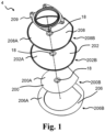
- Fig. 1 schematically illustrates an exploded view of an exemplary base plate 4 of an ostomy appliance.
- the base plate 4 comprises a first adhesive layer 200 having a distal surface 200A and a proximal surface 200B.
- the proximal surface 200B of the first adhesive layer 200 adheres to the user's skin.
- the base plate 4 comprises a second adhesive layer 202 having a distal surface 202A and a proximal surface 202B.
- the second adhesive layer 202 spans a larger surface area than the first adhesive layer 200, such as to provide a rim of the proximal surface 202 of the second adhesive layer 202 surrounding the proximal surface 200 of the first adhesive layer 200.
- the base plate 4 comprises a release liner 206, which may be peeled off by the user prior to applying the base plate 4 to the skin.
- the release liner 206 comprises a distal surface 206A and a proximal surface 206B.
- the distal surface 206A of the release liner 206 is covering the proximal surface of the first adhesive layer 200 and covering the proximal surface of the second adhesive layer 202 not covered by the first adhesive layer 200.
- the base plate 4 comprises a backing layer 208.
- the backing layer 208 is a protective layer protecting the adhesive layers, such as the first adhesive layer 200 and/or the second adhesive layer 202 from external strains and stress during use. Furthermore, the backing layer 208 also covers the adhesive layers, such as the first adhesive layer 200 and/or the second adhesive layer 202, such that the adhesive layers 200,202 does not adhere to clothes worn on top of the base plate 4.
- the backing layer 208 comprises a distal surface 208A and a proximal surface 208B.
- the distal surface 208A of the backing layer 208 is configured to face away from the skin of the user.
- the proximal surface 208B of the backing layer 208 is covering the second adhesive layer 202.
- the base plate 4 is a two-part ostomy appliance, thus comprising a coupling ring 209 for coupling an ostomy pouch to the base plate 4, such as to a distal side of the base plate 4.
- the base plate 4 comprises a stomal opening.
- the layers of the base plate 4, such as the first adhesive layer 200, the second adhesive layer 202 and the backing layer 208 as illustrated, may comprise stomal openings 18 for collectively forming the stomal opening of the base plate.
- Fig. 2 schematically illustrates an exploded view of an exemplary sensor patch 50, such as a sensor patch 50 being adapted for attachment to a base plate, such as the base plate 4 as illustrated in Fig. 1 .
- the sensor patch 50 is configured to be positioned between the skin of the user and the proximal side of the base plate 4.
- the sensor patch may be adapted for attachment to the first adhesive layer 200, such as the proximal surface 200B of the first adhesive layer 200, of the base plate 4.
- the sensor patch 50 is configured to be attached to the base plate such that the distal side 50A of the sensor patch 50 is attached to the proximal side of the base plate, such as to the proximal surface 200B of the first adhesive layer 200 of the base plate 4.
- the sensor patch 50 comprises a sensor assembly 204 comprising a plurality of electrodes 216. Each electrode 216 has respective connection parts 217 for connecting the plurality of electrodes 216 to respective terminal elements of a monitor device.
- the sensor assembly 204 may form a sensor assembly layer.
- the sensor assembly 204 has a distal side 204A and a proximal side 204B.
- the sensor assembly 204 comprises a support layer 214 with a proximal surface 214B.
- the electrodes 216 may be provided, such as formed, on the proximal surface 214B of the support layer 214, e.g. the electrodes 216 may be positioned on the proximal surface 214B of the support layer 214.
- the electrode assembly 204 comprises a masking element 218 having a distal surface 218A and a proximal surface 218B.
- the masking element 218 is configured to electrically insulate at least parts of electrodes 216 from adjacent layers, such as the first adhesive sensor layer 52.
- the masking element 218 covers or overlap with parts of the electrodes 216 when seen in the axial direction.
- the sensor patch 50 comprises a first adhesive sensor layer 52, with a proximal side 52B and a distal side 52A.
- the first adhesive sensor layer 52 is arranged on the proximal side 204B of the sensor assembly 204.
- the proximal side 52B of the first adhesive sensor layer 52 is configured to adhere to the user's skin.
- the combined base plate and sensor patch 50 forms an adhesive proximal surface configured to be applied to the skin surface of the user.
- the sensor patch comprises a first sensor release liner 54.
- the first sensor release liner 54 may comprise a distal surface 54A and a proximal surface 54B.
- the first sensor release liner 54 may be arranged to protect the first adhesive sensor layer 52.
- the distal surface 54A of the first sensor release liner 54 is facing the proximal surface 52B of the first adhesive sensor layer 52.
- the first sensor release liner 54 is configured to be peeled off by the user prior to application of the base plate with the attached sensor patch to the skin.
- the first adhesive sensor layer 52 may be laid out on the distal side 54A of the first sensor release liner 54.
- the sensor patch 50 comprises a second adhesive sensor layer 56, with a proximal side 56B and a distal side 56A.
- the second adhesive sensor layer 56 is arranged on the distal side 204A of the sensor assembly 204.
- the proximal side 56B of the second adhesive sensor layer 52 is configured to adhere to the base plate, such as the proximal surface of the first adhesive layer of the base plate.
- the exemplary sensor patch comprises a second sensor release liner 58.
- the second sensor release liner 58 may comprise a distal surface 58A and a proximal surface 58B.
- the second sensor release liner 58 may be arranged to protect the second adhesive sensor layer 56.
- the proximal surface 58B of the second sensor release liner 58 is facing the distal surface 56A of the second adhesive sensor layer 56.
- the second sensor release liner 58 is configured to be peeled off by the user prior to application of the sensor patch to the base plate.
- the second adhesive sensor layer 56 may be laid out on the proximal side 58B of the second sensor release liner 58.
- the illustrated exemplary sensor patch 50 comprises a second adhesive sensor layer 56 arranged on the distal side 204A of the sensor assembly 204
- an alternative sensor patch according to the disclosure may be provided without such a second adhesive sensor layer 56 and accompanying second sensor release liner 58.
- the distal surface of the sensor patch is the distal surface of the sensor assembly 204, in particular the distal surface of the support layer 214.
- the distal surface of the support layer 214 may be configured for attachment to the adhesive surface of a base plate.
- a sensor patch 50 having a first 52 and a second adhesive sensor layer 56 is illustrated and described, it is envisioned that a similar sensor patch without the second adhesive sensor layer 56 and accompanying second sensor release liner 58 may be provided according to the disclosure.
- the sensor patch 50 comprises a stomal opening.
- the layers of the sensor patch 50 such as the first adhesive sensor layer 52, the support layer 214 and the second adhesive sensor layer 56, as illustrated, may comprise stomal openings 60 for collectively forming the stomal opening of the sensor patch 50.
- the stomal opening of the sensor patch is configured to be aligned with the stomal opening of the base plate, such as to collectively form the stomal opening of the combined base plate and sensor patch 50.
- Fig. 3 schematically illustrates an exemplary electrode configuration 220 of electrodes 216 of an exemplary sensor assembly, such as the sensor assembly 204 as described with respect to Fig. 2 .
- the plurality of electrodes 216 comprises a first electrode 222, a second electrode 224, a third electrode 226, a fourth electrode 228, a fifth electrode 230, and a sixth electrode 232.
- the first electrode 222 comprises a first connection part 222A and the second electrode 224 comprises a second connection part 224A.
- the third electrode 226 comprises a third connection part 226A.
- the fourth electrode 228 comprises a fourth connection part 228A.
- the fifth electrode 230 comprises a fifth connection part 230A.
- the sixth electrode 232 comprise a sixth connection part 232A.
- the first electrode 222 may be a common ground electrode, such as to form sensors with respect to the remaining electrodes.
- the first electrode 222 comprises a first electrode part 234 for forming a ground for the second electrode 224.
- the first electrode 222 comprises a second electrode part 236 for forming a ground for the third electrode 226.
- the first electrode 222 comprises a third electrode part 238 for forming a ground for the fourth electrode 228.
- the first electrode 222 comprises a fourth electrode part 240 for forming a ground for the fifth electrode 230 and the sixth electrode 232.
- Fig. 4 schematically illustrates a cross section of a sensor patch 50, such as the sensor patch 50 as described with respect to Fig. 2 .
- the sensor patch 50 comprises a stomal opening 60 with a centre point 19.
- the stomal opening 60 may be made by the user, i.e. the sensor patch may be manufactured and/or sold without the stomal opening 60, but with a region adapted to form the stomal opening 60 with the centre point 19.
- the sensor patch 50 comprises sensor assembly 204, and a first adhesive sensor layer 52, a second adhesive sensor layer 56, a first sensor release liner 54, and a second sensor release liner 58.
- first adhesive sensor layer 52, the second adhesive sensor layer 56, the first sensor release liner 54, and the second sensor release liner 58 may be omitted.
- the illustrated exemplary sensor patch 50 comprises a second adhesive sensor layer 56 arranged on the distal side of the sensor assembly 204
- an alternative sensor patch according to the disclosure may be provided without such a second adhesive sensor layer 56 and accompanying second sensor release liner 58. Rather, in such an alternative sensor patch, the distal surface of the sensor patch may be the distal surface of the sensor assembly 204.
- the first adhesive sensor layer 52 comprises a first centre portion 62.
- the first adhesive sensor layer 52 comprises a first outer rim portion 64.
- the first adhesive sensor layer 52 comprises a first inner rim portion 66.
- the first centre portion 62 surrounds the first inner rim portion 66.
- the first outer rim portion 64 surrounds the first centre portion 62.
- the first outer rim portion 64 and the first inner rim portion 66 is the feature also referred to as the chamfered edge of the sensor patch 50.
- the chamfered edge of the sensor patch 50 is embodied in the sensor patch through the decreasing/increasing thicknesses of the first outer rim portion 64 and the first inner rim portion 66.
- a radial distance D82 of the first outer rim portion 64 is from the first outer rim portion 64 adjacent the first centre portion 62 to the first outer periphery 68 of the first adhesive sensor layer 52.
- a radial distance D86 of the first inner rim portion 66 is from the first inner periphery 69 of the first adhesive sensor layer 52 to the first centre portion 62, such as to the first centre portion 62 adjacent the first inner rim portion 66.
- a radial distance D84 from the centre point 19 to the first centre portion 62 adjacent the first inner rim portion 66.
- a radial distance D80 from the centre point 19 to the first outer rim portion 64 adjacent the first centre portion 62.
- the first centre portion 62 has a first centre thickness D62.
- the first outer rim portion 64 has a first outer rim thickness decreasing along a radial direction from adjacent the first centre portion 62 to a first outer periphery 68 of the first adhesive sensor layer 52.
- the first outer rim thickness adjacent the first centre portion 62 is the first centre thickness D62.
- the first outer rim thickness at the first outer periphery 68 of the first adhesive sensor layer 52 is a first minimum outer rim thickness D68.
- the first inner rim portion 66 has a first inner rim thickness increasing along a radial direction from a first inner periphery 69 of the first adhesive sensor layer 52 to the first centre portion 62.
- the first inner rim thickness adjacent the first centre portion 62 is the first centre thickness D62 and the first inner rim thickness at the first inner periphery 69 of the first adhesive sensor layer 52 is a first minimum inner rim thickness D69.
- the second adhesive sensor layer 56 comprises a second centre portion 72.
- the second adhesive sensor layer 56 comprises a second outer rim portion 74.
- the second adhesive sensor layer 56 comprises a second inner rim portion 76.
- the second centre portion 72 surrounds the second inner rim portion 76.
- the second outer rim portion 74 surrounds the second centre portion 72.
- a radial distance D92 of the second outer rim portion 74 is from the second outer rim portion 74 adjacent the second centre portion 72 to the second outer periphery 78 of the second adhesive sensor layer 56.
- a radial distance D96 of the second inner rim portion 76 from the second inner periphery 79 of the second adhesive sensor layer 56 to the second centre portion 72, such as to the second centre portion 72 adjacent the second inner rim portion 76.
- a radial distance D94 from the centre point 19 to the second centre portion 72 adjacent the second inner rim portion 76.
- a radial distance D90 from the centre point 19 to the second outer rim portion 74 adjacent the second centre portion 72.
- the second centre portion 72 has a second centre thickness D72.
- the second outer rim portion 74 has a second outer rim thickness decreasing along a radial direction from adjacent the second centre portion 72 to a second outer periphery 78 of the second adhesive sensor layer 56.
- the second outer rim thickness adjacent the second centre portion 72 is the second centre thickness D72.
- the second outer rim thickness at the second outer periphery 78 of the second adhesive sensor layer 56 is a second minimum outer rim thickness D78.
- the second inner rim portion 76 has a second inner rim thickness increasing along a radial direction from a second inner periphery 79 of the second adhesive sensor layer 56 to the second centre portion 72.
- the second inner rim thickness adjacent the second centre portion 72 is the second centre thickness D72 and the second inner rim thickness at the second inner periphery 79 of the second adhesive sensor layer 56 is a second minimum inner rim thickness D79.
- the first outer rim thickness, the first inner rim thickness, the second outer rim thickness and the second inner rim thickness is shown to decrease/increase substantially linearly.
- one or more of the first outer rim thickness, the first inner rim thickness, the second outer rim thickness and the second inner rim thickness may decrease/increase convexly or concavely along the radial direction.
- a radial distance D10 from the centre point to a first loop formed by a first electrode of the plurality of electrodes 216 is less than the radial distance D80 from the centre point 19 to the first outer rim portion 64, such as to the first outer rim portion 64 adjacent to the first centre portion 62.
- the radial distance D10 from the centre point to the first loop is less than the radial distance D90 from the centre point 19 to the second outer rim portion 74, such as to the second outer rim portion 74 adjacent to the second centre portion 72.
- a radial distance D12 from the centre point to a second loop formed by a second electrode of the plurality of electrodes 216 is less than the radial distance D80 from the centre point 19 to the first outer rim portion 64, such as to the first outer rim portion 64 adjacent to the first centre portion 62.
- the radial distance D12 from the centre point to the second loop is less than the radial distance D90 from the centre point 19 to the second outer rim portion 74, such as to the second outer rim portion 74 adjacent to the second centre portion 72.
- the radial distance D12 from the centre point to the second loop is less than the radial distance D10 from the centre point to the first loop.
- a radial distance D14 from the centre point to a third loop formed by a third electrode of the plurality of electrodes 216 is less than the radial distance D80 from the centre point 19 to the first outer rim portion 64, such as to the first outer rim portion 64 adjacent to the first centre portion 62.
- the radial distance D14 from the centre point to the third loop is less than the radial distance D90 from the centre point 19 to the second outer rim portion 74, such as to the second outer rim portion 74 adjacent to the second centre portion 72.
- the radial distance D14 from the centre point to the third loop is less than the radial distance D12 from the centre point to the second loop.
- Fig. 5 is a schematic block diagram of an exemplary method 1000 for manufacturing a sensor patch, such as a sensor patch as described with respect to one or more of the previous figures.
- the method 1000 comprises providing 1002 a first adhesive sensor material and laying out 1004 a layer of the first adhesive sensor material for forming a first adhesive sensor layer of the sensor patch.
- the first adhesive sensor material is laid out 1004 to form a first centre portion and a first outer rim portion surrounding the first centre portion, wherein the first centre portion has a first centre thickness and the first outer rim portion has a first outer rim thickness gradually decreasing along a radial direction from adjacent the first centre portion to the first outer periphery of the first adhesive sensor layer.
- the first adhesive sensor material is laid out 1004 such that the first outer rim thickness adjacent the first centre portion is the first centre thickness and the first outer rim thickness at the first outer periphery of the first adhesive sensor layer is a first minimum outer rim thickness.
- Laying out 1004 of the first adhesive sensor material may further comprise forming a first inner rim portion being surrounded by the first centre portion, and wherein the first inner rim portion has a first outer rim thickness gradually increasing along a radial direction from a first inner periphery of the first adhesive sensor layer to the first centre portion adjacent the first inner rim portion.
- Laying out 1004 the layer of the first adhesive sensor material for forming the first adhesive sensor layer may comprise extrution of the first adhesive sensor layer, moulding, such as injection moulding of the first adhesive sensor layer and/or scraping of the first adhesive sensor layer onto a dinted surface.
- Laying out 1004 the layer of the first adhesive sensor material may comprise a post-process of forming or improving the rim portions.
- the method 1000 comprises providing 1006 a sensor assembly comprising a plurality of electrodes, such as the sensor assembly as described with respect to the previous figures.
- the electrodes including at least a first electrode and a second electrode for forming a first sensor.
- the method 1000 comprises arranging 1008 the sensor assembly on a distal side of the first adhesive sensor layer, wherein a proximal side of the first adhesive sensor layer is adapted for attachment of the sensor patch to the skin surface of the user.
- the method 1000 optionally comprises providing 1010 a first sensor release liner.
- Laying out 1004 the layer of the first adhesive sensor material may comprise laying out 1004 the layer of the first adhesive sensor material on a distal side of the first sensor release liner.
- Providing 1002 the first adhesive sensor material may optionally comprise sorting 1012 hydrocolloids of the first adhesive sensor material according to grain size.
- sorting 1012 the hydrocolloids may be done to achieve a smaller average and/or maximum gran size, such as to provide for a thinner rim portion of the first adhesive layer.
- laying out 1004 the layer of the first adhesive sensor material may comprise laying out the layer of the first adhesive sensor material for forming the first centre portion with hydrocolloids having a first centre average grain size and/or a first centre maximum grain size, and laying out the layer of the first adhesive sensor material for forming the first outer rim portion and/or the first inner rim portion with hydrocolloids having a first outer rim average grain size and/or a first outer rim average grain size and/or a first inner rim average grain size and/or a first inner rim average grain size, respectively, wherein the first outer rim average/maximum grain size and/or the first inner rim average/maximum grain size is less than the first centre average/maximum grain size.
- the first rim portions may achieve a thinner thickness, e.g. at the peripheries than the first centre portion.
- the method 1000 may comprise providing 1102 a second adhesive sensor material and laying out 1104 a layer of the second adhesive sensor material for forming a second adhesive sensor layer of the sensor patch.
- the illustrated/disclosed method includes providing 1102 a second adhesive sensor material for forming a second adhesive sensor layer, it is envisioned that an alternative method omits the steps related to such a second adhesive sensor layer, such that the resulting sensor patch has a distal surface being the distal surface of the sensor assembly, and such that the resulting sensor patch has a first adhesive sensor layer only.
- the second adhesive sensor material is laid out 1104 to form a second centre portion and a second outer rim portion surrounding the second centre portion, wherein the second centre portion has a second centre thickness and the second outer rim portion has a second outer rim thickness gradually decreasing along a radial direction from adjacent the second centre portion to the second outer periphery of the second adhesive sensor layer. Further, the second adhesive sensor material is laid out 1104 such that the second outer rim thickness adjacent the second centre portion is the second centre thickness and the second outer rim thickness at the second outer periphery of the second adhesive sensor layer is a second minimum outer rim thickness.
- Laying out 1104 of the second adhesive sensor material may further comprise forming a second inner rim portion being surrounded by the second centre portion, and wherein the second inner rim portion has a second outer rim thickness gradually increasing along a radial direction from a second inner periphery of the second adhesive sensor layer to the second centre portion adjacent the second inner rim portion.
- the layer of the second adhesive sensor material for forming the second adhesive sensor layer may comprise extrusion of the second adhesive sensor layer, moulding, such as injection moulding of the second adhesive sensor layer and/or scraping of the second adhesive sensor layer onto a dinted surface.
- the layer of the second adhesive sensor material may comprise a post-process of forming or improving the rim portions.
- the method 1000 optionally comprises providing 1110 a second sensor release liner.
- Laying out 1104 the layer of the second adhesive sensor material may comprise laying out 1104 the layer of the second adhesive sensor material on a proximal side of the second sensor release liner.
- Providing 1102 the second adhesive sensor material may optionally comprise sorting 1112 hydrocolloids of the second adhesive sensor material according to grain size.
- sorting 1112 the hydrocolloids may be done to achieve a smaller average and/or maximum gran size, such as to provide for a thinner rim portion of the second adhesive layer.
- laying out 1104 the layer of the second adhesive sensor material may comprise laying out the layer of the second adhesive sensor material for forming the second centre portion with hydrocolloids having a second centre average/maximum grain size, and laying out the layer of the second adhesive sensor material for forming the second outer rim portion and/or the second inner rim portion with hydrocolloids having a second outer rim average/maximum grain size and/or a second inner rim average/maximum grain size, respectively, wherein the second outer rim average/maximum grain size and/or the second inner rim average/maximum grain size is less than the second centre average/maximum grain size.
- the second rim portions may achieve a thinner thickness, e.g. at the peripheries than the second centre portion.
- Providing a sensor patch, wherein the adhesive has a decreasing outer rim and/or an increasing inner rim facilitates a smoother transition at the interface between the sensor patch and the adhesive surface of the base plate whereto the sensor patch is applied.
- the risk of creating potential creases between the skin of the user and the adhesive surface of the sensor patch and base plate is reduced. Creases between the adhesive surface and the skin of the user could weaken the adhesion and could lead to an increased risk of leakage.
- the risk of leakage caused by the sensor patch may be reduced by providing a decreasing outer rim and/or an increasing inner rim.
Landscapes
- Health & Medical Sciences (AREA)
- Life Sciences & Earth Sciences (AREA)
- Veterinary Medicine (AREA)
- Public Health (AREA)
- Engineering & Computer Science (AREA)
- Biomedical Technology (AREA)
- Heart & Thoracic Surgery (AREA)
- Animal Behavior & Ethology (AREA)
- General Health & Medical Sciences (AREA)
- Nursing (AREA)
- Epidemiology (AREA)
- Vascular Medicine (AREA)
- Orthopedic Medicine & Surgery (AREA)
- Medical Informatics (AREA)
- Biophysics (AREA)
- Pathology (AREA)
- Physics & Mathematics (AREA)
- Molecular Biology (AREA)
- Surgery (AREA)
- Chemical & Material Sciences (AREA)
- Dispersion Chemistry (AREA)
- Endocrinology (AREA)
- Gastroenterology & Hepatology (AREA)
- Physiology (AREA)
- Orthopedics, Nursing, And Contraception (AREA)
Abstract
Description
- The present disclosure relates to a sensor patch for attachment to base plate for an ostomy appliance. In particular the present disclosure relates to the thickness of such a sensor patch.
- Stomal output often contains body fluids and visceral contents that are aggressive to both the skin of a user and to ostomy devices, these have a detrimental effect on the efficiency and integrity of the adhesive materials that are applied to attach the ostomy device to the user's skin surface. For users in general safe, reliable and efficient ostomy devices are evidently highly desirable.
- However, a particularly major and persistent concern of a large population of ostomists continues to be failure of the base plate adhesive attaching the ostomy appliance to the user's skin surface, because such failure almost inevitably leads to embarrassing and stigmatising leakage incidents. Such incidents in turn are known from several user interviews to lead to a reduced quality-of-life feeling. Adhesive failure of the base plate adhesive can result from various reasons. Most often, a leakage incident is caused by stomal output entering between the proximal surface of the base plate and the user's skin, e.g. due to less-than-optimal attachment of the base plate to the skin arising from e.g. uneven skin surface or skin folds. This undesirable progression of stomal output "underneath" the adhesive leads to deterioration and/or weakening of the adhesive material carrying the weight and providing the seal of the ostomy appliance. Often such failure happens surprisingly fast and is only detectable for the user once the failure has already become so severe that leakage occurs, requiring immediate change of the ostomy appliance and possibly also of the user's clothes.
- In other instances, the primary factor of adhesive failure is simply a question of how much time has elapsed since the base plate of the ostomy appliance was first applied to the user's skin surface. In addition to the output from the stoma itself, the peristomal skin surface continuously secretes some moisture (e.g. sweat). To mitigate this, most often adhesives of base plates for ostomy devices include hydrocolloid materials which are capable of absorbing high levels of moisture, thereby stabilizing the polymer matrix of the adhesive material and prolonging the lifetime ("wear time") of the base plate. However, eventually the adhesion capability of the base plate no longer can support the force exerted on the base plate from the load of the output collecting bag, and the appliance must be replaced.
- As there can be considerable differences in the severity and/or speed by which adhesive failure and potentially leakage occur, which differences at least to some extent are correlated to various factors including those presented above, a mere indication that failure or leakage is imminent, or that it has already occurred, fails to represent a reliable and satisfactory solution to the problem of avoiding sudden embarrassing and stigmatising leakage incidents in ostomy appliances. In other words, the users of ostomy appliances could greatly benefit from an appliance solution which provides them with better guidance and options regarding how and - not least - how quickly to react to beginning failure or leakage of the adhesive of the base plate of the appliance. More generally, ostomists and health care professionals alike would welcome improvements in ostomy devices to reduce or eliminate the occurrence of sudden leakage incidents.
- It is an object of the present disclosure to provide a sensor patch and a base plate for facilitating reliable and/or improved detection of risk of failure of an ostomy appliance and/or improved detection of risk of leakage. The disclosed sensor patch and base plate may be provided to facilitate detection of risk of failure and/or risk of leakage with respect to an adhesive base plate of the ostomy appliance.
- It is a further object of the present disclosure to provide ways of facilitating attachment of a sensor patch to an ostomy appliance, such as a base plate of the ostomy appliance, which reduces the risk of compromising the capability of the ostomy appliance to avoid leakage, in particular between the skin surface of the user and the adhesive surface of the base plate. In particular, it is an object of the present disclosure to reduce the edge of the sensor patch, such that a transition from the adhesive surface of a base plate to the adhesive surface of the sensor patch attached to the adhesive surface of the base plate is a smooth as possible. In other words, it is an object of the present disclosure to reduce the edge formed between the adhesive surface of the base plate and the sensor patch attached thereto. In particular, it is envisioned that the presence of such an edge may cause unfavourable effects to the quality of adhesion of the base plate/sensor patch to the skin surface of the user, and as such, it is an object to reduce such an edge.
- Thus, the present disclosure relates to a sensor patch and a method for manufacturing a sensor patch. Also, the present disclosure relates to a base plate for an ostomy appliance.
- Accordingly, a sensor patch for attachment to a base plate for an ostomy appliance is disclosed. The sensor patch has a proximal side and a distal side. The distal side is adapted for attachment to an adhesive surface of the base plate, wherein the adhesive surface of the base plate is adapted for attachment of the base plate to the skin surface of a user.
- The sensor patch comprises: a sensor assembly comprising a plurality of electrodes including a first electrode and a second electrode for forming a first sensor; and a first adhesive sensor layer forming the proximal side of the sensor patch and being adapted for attachment of the sensor patch to the skin surface of the user. The first adhesive sensor layer comprises a first centre portion having a first centre thickness and a first outer rim portion surrounding the first centre portion. The first outer rim portion has a first outer rim thickness decreasing along a radial direction from adjacent the first centre portion to a first outer periphery of the first adhesive sensor layer. The first outer rim thickness adjacent the centre portion is the first centre thickness and the first outer rim thickness at the first outer periphery of the first adhesive sensor layer is a first minimum outer rim thickness.
- The sensor patch is adapted to form a stomal opening with a centre point. The stomal opening is configured to allow passage of output through the stomal opening and into an ostomy pouch attached to the base plate.
- Thereby is provided a sensor patch having a chamfered edge, whereby the transition between a base plate and the sensor patch attached to the base plate is smoothed. The sensor patch having the chamfered edge may reduce the potentially unfavourable effects of having a sensor patch attached to the adhesive surface of a base plate, such as the effects the attached sensor patch may have on the quality of adhesion to the skin surface.
- Also disclosed is a method for manufacturing a sensor patch, such as the above-disclosed sensor patch, such as a sensor patch having a proximal side and a distal side and being adapted for attachment of the distal side to an adhesive surface of a base plate for an ostomy appliance wherein the adhesive surface of the base plate is adapted for attachment of the base plate to the skin surface of a user.
- The method comprises providing a first adhesive sensor material and laying out a layer of the first adhesive sensor material for forming a first adhesive sensor layer of the sensor patch, wherein the first adhesive sensor material is laid out to form a first centre portion and a first outer rim portion surrounding the first centre portion, wherein the first centre portion has a first centre thickness and the first outer rim portion has a first outer rim thickness gradually decreasing along a radial direction from adjacent the first centre portion to the first outer periphery of the first adhesive sensor layer, and wherein the first outer rim thickness adjacent the first centre portion is the first centre thickness and the first outer rim thickness at the first outer periphery of the first adhesive sensor layer is a first minimum outer rim thickness.
- The method comprises providing a sensor assembly comprising a plurality of electrodes including a first electrode and a second electrode for forming a first sensor.
- The method comprises arranging the sensor assembly on a distal side of the first adhesive sensor layer, wherein a proximal side of the first adhesive sensor layer is adapted for attachment of the sensor patch to the skin surface of the user.
- Thereby is provided a method for manufacturing a sensor patch having a chamfered edge facilitating that the transition between a base plate and the sensor patch attached to the base plate is smoothed.
- Also disclosed is a base plate for an ostomy appliance having a proximal adhesive surface adapted for attachment of the base plate to the skin surface of a user.
- Embodiments of the disclosure will be described in more detail in the following with regard to the accompanying figures. The figures show one way of implementing the present invention and are not to be construed as being limiting to other possible embodiments falling within the scope of the attached claim set.
-
Fig. 1 schematically illustrates an exploded view of an exemplary base plate, -
Fig. 2 schematically illustrates an exploded view of an exemplary sensor patch, -
Fig. 3 schematically illustrates an exemplary electrode configuration, -
Fig. 4 schematically illustrates a cross section of a sensor patch, and -
Fig. 5 is a schematic block diagram of an exemplary method. - In the following Detailed Description, reference is made to the accompanying drawings, which form a part hereof, and in which is shown by way of illustration specific embodiments in which the invention may be practiced. In this regard, directional terminology, such as "top," "bottom," "front," "back," "leading," "trailing," etc., is used with respect to the orientation of the Figure(s) being described. Because components of embodiments can be positioned in a number of different orientations, the directional terminology is used for purposes of illustration and is in no way limiting. It is to be understood that other embodiments may be utilized, and structural or logical changes may be made without departing from the scope of the present invention. The following detailed description, therefore, is not to be taken in a limiting sense, and the scope of the present invention is defined by the appended claims.
- It is to be understood that the features of the various exemplary embodiments described herein may be combined with each other, unless specifically noted otherwise.
- Throughout this disclosure, the words "stoma" and "ostomy" are used to denote a surgically created opening bypassing the intestines or urinary tract system of a person. The words are used interchangeably, and no differentiated meaning is intended. The same applies for any words or phrases derived from these, e.g. "stomal", "ostomies" etc. Also, the solid and liquid wastes emanating from the stoma may be referred to as both stomal "output," "waste(s)," and "fluids" interchangeably. A subject having undergone ostomy surgery may be referred to as "ostomist" or "ostomate" - moreover, also as "patient" or "user". However, in some cases "user" may also relate or refer to a health care professional (HCP), such as a surgeon or an ostomy care nurse or others. In those cases, it will either be explicitly stated, or be implicit from the context that the "user" is not the "patient" him- or herself.
- In the following, whenever referring to proximal side of a device or part of a device, the referral is to the skin-facing side, when the ostomy appliance is worn by a user. Likewise, whenever referring to the distal side of a device or part of a device, the referral is to the side facing away from the skin, when the ostomy appliance is worn by a user. In other words, the proximal side is the side closest to the user, when the appliance is fitted on a user and the distal side is the opposite side - the side furthest away from the user in use.
- The axial direction is defined as the direction of the stoma, when the appliance is worn by a user. Thus, the axial direction is generally perpendicular to the skin or abdominal surface of the user.
- The radial direction is defined as transverse to the axial direction that is transversely to the direction of the stoma, i.e. "across" the distal/proximal surface of the base plate. In some sentences, the words "inner" and "outer" may be used. These qualifiers should generally be perceived with respect to the radial direction, such that a reference to an "outer" element means that the element is farther away from a centre portion of the ostomy appliance than an element referenced as "inner". In addition, "innermost" should be interpreted as the portion of a component forming a centre of the component and/or being adjacent to the centre of the component. In analogy, "outermost" should be interpreted as a portion of a component forming an outer edge or outer contour of a component and/or being adjacent to that outer edge or outer contour.
- The use of the word "substantially" as a qualifier to certain features or effects in this disclosure is intended to simply mean that any deviations are within tolerances that would normally be expected by the skilled person in the relevant field.
- The use of the word "generally" as a qualifier to certain features or effects in this disclosure is intended to simply mean - for a structural feature: that a majority or major portion of such feature exhibits the characteristic in question, and - for a functional feature or an effect: that a majority of outcomes involving the characteristic provide the effect, but that exceptionally outcomes do no provide the effect.
- The use of the word "essentially" as a qualifier to certain structural and functional features or effects in this disclosure is used for emphasizing what is the most important focus of something or fact about something (i.e. a feature may have or fulfil a variety of effects, but when the disclosure discusses one effect as being "essentially" provided, this is the focus and the most important effect in relation to the disclosure).
- Throughout the disclosure, the use of the terms "first", "second", "third", "fourth", "primary", "secondary", "tertiary" etc. does not imply any particular order or importance but are included merely to identify individual elements. Furthermore, the labelling of a first element does not imply the presence of a second element and vice versa.
- Disclosed is a sensor patch for attachment to a base plate for an ostomy appliance. Such as to facilitate detection of moisture propagation in the adhesive material provided for attaching the base plate to the skin surface of a user as well as detection of increased risk of leakage. For example, the sensor patch may allow electronic measurements of performance of the base plate and/or to facilitate detection of increasing risks of leakage and/or to facilitate detection of decreasing adherence of the base plate to the skin of the user.
- The ostomy appliance comprises a base plate and an ostomy pouch (also referred to as an ostomy bag). The ostomy appliance may be a colostomy appliance, an ileostomy appliance or a urostomy appliance. The ostomy appliance may be a two-part ostomy appliance, i.e. the base plate and the ostomy pouch may be releasably coupled e.g. with a mechanical and/or an adhesive coupling, e.g. to allow that a plurality of ostomy pouches can be utilized (exchanged) with one base plate. For example, the base plate may comprise a coupling ring for coupling an ostomy pouch to the base plate. Further, a two-part ostomy appliance may facilitate correct application of the base plate to skin, e.g. to an improved user sight of the stomal region. Alternatively, the ostomy appliance may be a one-part ostomy appliance, i.e. the base plate and the ostomy pouch may be fixedly attached to each other. The base plate is configured for coupling to a user's stoma and/or skin surrounding the stoma, such as a peristomal skin area.
- The base plate may comprise a first adhesive layer, i.e. a first layer of an adhesive material. During use, a proximal surface of the first adhesive layer adheres to the user's skin in the peristomal area and/or to additional seals, such as sealing paste, sealing tape and/or sealing ring. The first adhesive layer may be made of a first composition. The first composition may comprise one or more polyisobutenes and/or styrene-isoprene-styrene. The first composition may comprise one or more hydrocolloids. The first composition may comprise one or more water soluble or water swellable hydrocolloids. The first composition may be a pressure sensitive adhesive composition suitable for medical purposes comprising a rubbery elastomeric base and one or more water soluble or water swellable hydrocolloids. The first adhesive layer may comprise a distal surface and a proximal surface. The proximal surface of the first adhesive layer may be configured to adhere to the user's skin. The distal surface of the first adhesive layer may be configured to face away from the skin of the user.
- The first adhesive layer may form the adhesive surface of the base plate adapted for attachment of the base plate to the skin surface of the user. The first adhesive layer may form part of the adhesive surface of the base plate adapted for attachment of the base plate to the skin surface of the user.
- The base plate may comprise a second adhesive layer, i.e. a second layer of an adhesive material, also denoted rim adhesive layer. The second adhesive layer may be of a different adhesive material than the first adhesive layer. The second adhesive layer may be made of a second composition. The second composition may comprise one or more polyisobutenes and/or styrene-isoprene-styrene. The second composition may comprise one or more hydrocolloids. The second composition may comprise one or more water soluble or water swellable hydrocolloids. The second composition may be a pressure sensitive adhesive composition suitable for medical purposes comprising a rubbery elastomeric base and one or more water soluble or water swellable hydrocolloids. The second adhesive layer may comprise a distal surface and a proximal surface.
- The proximal surface of the second adhesive layer may be configured to adhere to the user's skin, e.g. at least at a rim portion of the second adhesive layer. The distal surface of the second adhesive layer may be configured to face away from the skin of the user. The second adhesive layer may be covering a larger area than the first adhesive layer, e.g. such that the proximal surface of the second adhesive layer forms an adhesive rim surrounding the first adhesive layer.
- Different ratio of contents may change properties of the first adhesive layer and/or the second adhesive layer. The second adhesive layer and the first adhesive layer may have different properties. The second adhesive layer (second composition) and the first adhesive layer (first composition) may have different ratios of polyisobutenes, styrene-isoprene-styrene, and/or hydrocolloids. For example, the second adhesive layer may provide a stronger attachment to the skin compared to attachment to the skin provided by the first adhesive layer. Alternatively or additionally, the second adhesive layer may be thinner than the first adhesive layer. Alternatively or additionally, the second adhesive layer may be less water and/or sweat absorbing than the first adhesive layer. Alternatively or additionally, the second adhesive layer may be less mouldable than the first adhesive layer. The second adhesive layer may provide a second barrier against leakage.
- The second adhesive layer may form part of the adhesive surface of the base plate adapted for attachment of the base plate to the skin surface of the user. The first adhesive layer and the second adhesive layer may form the adhesive surface of the base plate adapted for attachment of the base plate to the skin surface of the user.
- The first adhesive layer and/or the second adhesive layer may comprise a centre portion with a centre thickness, and an outer rim portion surrounding the centre portion. The outer rim portion may have an outer rim thickness, e.g. decreasing along a radial direction from adjacent the centre portion to an outer periphery of the first adhesive layer and/or the second adhesive layer. The outer rim thickness may be decreasing convexly, concavely, or substantially linearly along the radial direction from adjacent the centre portion to the outer periphery. The outer rim thickness adjacent the centre portion may be the centre thickness. The outer rim thickness at the outer periphery may be a minimum outer rim thickness. The centre thickness may be between 0.5 mm and 1.5 mm. The minimum outer rim thickness may be less than 0.5 mm, such as less than 0.4 mm, such as less than 0.3 mm, such as less than 0.1 mm.
- The first adhesive layer and/or the second adhesive layer may surround an opening, such as the stomal opening. The first adhesive layer and/or the second adhesive layer may have an inner rim portion being surrounded by the centre portion. The inner rim portion may have an inner rim thickness increasing along a radial direction from an inner periphery of the first adhesive layer and/or the second adhesive layer to the centre portion. The inner rim thickness may be increasing convexly, concavely, or substantially linearly along the radial direction from the inner periphery to the centre portion. The inner rim thickness adjacent the centre portion may be the centre thickness. The inner rim thickness at the inner periphery may be a minimum inner rim thickness. The minimum inner rim thickness may be less than 0.5 mm, such as less than 0.4 mm, such as less than 0.3 mm, such as less than 0.1 mm.
- Providing a base plate wherein the adhesive, such as the first adhesive layer and/or the second adhesive layer, has a decreasing outer rim and/or an increasing inner rim facilitates a smoother transition between the base plate and the skin of the user at the edge of the base plate. Thereby, the risk of clothes adhering to the edge of the base plate and potentially peeling the base plate off the skin, may be reduced. Thus, decreasing the risk of leakage caused by the base plate adhering insufficiently to the skin of the user.
- The base plate may comprise a release liner, which may be peeled off by the user prior to applying the base plate to the skin. The release liner may be configured to protect the adhesive layers prior to applying the base plate to the skin. The release liner may comprise a distal surface and a proximal surface. The release liner may be configured to, e.g. prior to applying the base plate to the skin, covering the proximal surface of the first adhesive layer and/or covering the proximal surface of the second adhesive layer, such as the proximal surface of the second adhesive layer not covered by the first adhesive layer. The distal surface of the release liner may be configured to, e.g. prior to applying the base plate to the skin, face the proximal surface of the first adhesive layer and/or the proximal surface of the second adhesive layer, such as the proximal surface of the second adhesive layer not covered by the first adhesive layer.
- The base plate may comprise a backing layer. The backing layer may be a protective layer protecting the adhesive layers, such as the first adhesive layer and/or the second adhesive layer from external strains and stress during use. Furthermore, the backing layer may also cover the adhesive layers, such as the first adhesive layer and/or the second adhesive layer, such that the adhesive layers do not adhere to clothes worn on top of the base plate. The backing layer may comprise a distal surface and a proximal surface. The distal surface of the backing layer may be configured to face away from the skin of the user. The proximal surface of the backing layer may be facing the second adhesive layer. The second adhesive layer may be provided on the proximal surface of the backing layer.
- The base plate may comprise a stomal opening. Each layer of the base plate may comprise stomal openings for collectively forming the stomal opening of the base plate. The stomal opening may be provided in a centre portion of the base plate. The centre portion of the base plate may be surrounding the stomal opening. The stomal opening may be configured to receive a stoma of the user and/or the stomal opening may be configured to allow output from the stoma to pass through the stomal opening an into an ostomy pouch attached to the base plate. For example, the stomal opening may be configured to allow passage of output from the proximal side of the base plate to a distal side of the base plate. The size and/or shape of the stomal opening may typically be adjusted by the user or nurse before application of the base plate to accommodate the user's stoma.
- The sensor patch according to the present disclosure is adapted for attachment to the base plate. For example, the sensor patch may be configured to be positioned between the skin of the user and the proximal side of the base plate. For example, the sensor patch may be adapted for attachment to the first adhesive layer of the base plate. For example, a distal side of the sensor patch may be configured to be facing the proximal surface of the first adhesive layer of the base plate. For example, the sensor patch, such as a distal side of the sensor patch may be configured to adhere to the proximal surface of the first adhesive layer of the base plate.
- The sensor patch may comprise a stomal opening and/or the sensor patch may be adapted to form a stomal opening. Each layer of the sensor patch, as described below, may comprise stomal openings and/or be adapted to form a stomal opening for collectively forming the stomal opening of the sensor patch. The stomal opening of the sensor patch may be configured to be aligned with the stomal opening of the base plate, such as to collectively form the stomal opening of the combined base plate and sensor patch. The size and/or shape of the stomal opening of the sensor patch may be adjusted by the user or nurse before application of the sensor patch to accommodate the user's stoma. The size and/or shape of the stomal opening of the sensor patch may be adjusted together with adjustment of the stomal opening of the base plate, e.g. after the sensor patch has been attached to the base plate. The stomal opening(s) may have a centre point.
- The sensor patch comprises a sensor assembly. The sensor assembly may form a sensor assembly layer. The sensor assembly may have a distal side and a proximal side. The sensor patch may be configured to be positioned on the base plate such that the distal surface of the sensor assembly is coupled to the proximal adhesive surface of the base plate.
- The sensor assembly comprises a plurality of electrodes. The plurality of electrodes includes a first electrode and a second electrode for forming a first sensor. The plurality of electrodes may include a third electrode, a fourth electrode, a fifth electrode and/or a sixth electrode. The first electrode may be a common ground electrode. For example, a second sensor may be formed by the first electrode and the third electrode, a third sensor may be formed by the first electrode and the fourth electrode, a fourth electrode may be formed by the first electrode and the fifth electrode, and/or a fifth electrode may be formed by the first electrode and the sixth electrode. Each electrode may have respective connection parts for connecting the electrodes to respective terminal elements of a monitor device.
- The plurality of electrodes is electrically conductive and may comprise one or more of metallic (e.g. silver, copper, gold, titanium, aluminium, stainless steel), ceramic (e.g. ITO), polymeric (e.g. PEDOT, PANI, PPy), and carbonaceous (e.g. carbon black, carbon nanotube, carbon fibre, graphene, graphite) materials.
- The plurality of electrodes may form loops and/or open loops. Open loop electrode(s) enables electrode arrangement in few or a single electrode layer.
- The sensor assembly may comprise a support layer, e.g. with a proximal surface and a distal surface. The plurality of electrodes may be provided, such as formed, on the proximal surface of the support layer, e.g. the plurality of electrodes may be positioned on the proximal surface of the support layer.
- The sensor assembly may comprise a masking element, e.g. with a proximal surface and a distal surface. The masking element may be configured to electrically insulate at least parts of the plurality of electrodes from proximal layers, such as a first adhesive sensor layer. The masking element may cover or overlap parts of the plurality electrodes, e.g. when seen in the axial direction.
- The sensor patch comprises a first adhesive sensor layer, e.g. with a proximal side and a distal side. The first adhesive sensor layer may be arranged on a proximal side of the sensor assembly. The first adhesive sensor layer, such as the proximal side of the first adhesive sensor layer, forms the proximal side of the sensor patch. The proximal side of the first adhesive sensor layer may be configured to adhere to the user's skin. Thus, after being applied to the base plate, the combined base plate and sensor patch may form an adhesive proximal surface configured to be applied to the skin surface of the user. The first adhesive sensor layer may be made of a first adhesive sensor material, such as the first composition, the second composition or a third composition. The third composition may comprise one or more polyisobutenes and/or styrene-isoprene-styrene. The third composition may comprise one or more hydrocolloids. The third composition may comprise one or more water soluble or water swellable hydrocolloids. The third composition may be a pressure sensitive adhesive composition suitable for medical purposes comprising a rubbery elastomeric base and one or more water soluble or water swellable hydrocolloids.
- The first adhesive sensor layer comprises a first centre portion. The first centre portion has a first centre thickness. The first adhesive sensor layer comprises a first outer rim portion surrounding the first centre portion. The first outer rim portion has a first outer rim thickness decreasing along a radial direction from adjacent the first centre portion to a first outer periphery of the first adhesive sensor layer. The first outer rim thickness may be decreasing convexly, concavely, or substantially linearly along the radial direction from adjacent the first centre portion to the first outer periphery of the first adhesive sensor layer. The first outer rim thickness adjacent the first centre portion is the first centre thickness. The first outer rim thickness at the first outer periphery of the first adhesive sensor layer is a first minimum outer rim thickness. The first centre thickness may be between 0.5 mm and 1.5 mm. The first minimum outer rim thickness may be less than 0.5 mm, such as less than 0.4 mm, such as less than 0.3 mm, such as less than 0.1 mm. A radial distance from the centre point to the first outer rim portion adjacent the first centre portion may be between 15-35 mm. A radial distance from the first outer rim portion adjacent the first centre portion to the first outer periphery of the first adhesive sensor layer may be between 0.5-20 mm. A radial distance from the centre point to the first outer periphery of the first adhesive sensor layer may be between 15.5-55 mm, such as between 20-45 mm, such as between 25-40 mm, such as between 30-35 mm.
- Thereby is provided that the sensor patch, in particular the first adhesive sensor layer of the sensor patch, has a chamfered edge, whereby a smooth transition between an adhesive surface of a base plate and the sensor patch attached thereto is provided. The smooth transition reduces the potentially unfavourable effects of having a sensor patch attached to the adhesive surface of the base plate. For example, the presence of an unchamfered edge may cause increased risk of leakage from the base plate, e.g. due to insufficient adhesion to the skin surface, or cause increased risk of skin irritation, e.g. due to an unchamfered edge irritating the skin.
- The first adhesive sensor layer may surround an opening, such as the stomal opening and/or an opening larger than the stomal opening. The first adhesive sensor layer may have a first inner rim portion being surrounded by the first centre portion. The first inner rim portion may have a first inner rim thickness increasing along a radial direction from a first inner periphery of the first adhesive sensor layer to the first centre portion. The first inner rim thickness may be increasing convexly, concavely, or substantially linearly along the radial direction from the first inner periphery of the first adhesive sensor layer to the first centre portion. The first inner rim thickness adjacent the first centre portion may be the first centre thickness. The first inner rim thickness at the first inner periphery of the first adhesive sensor layer may be a first minimum inner rim thickness. The first minimum inner rim thickness may be less than 0.5 mm, such as less than 0.4 mm, such as less than 0.3 mm, such as less than 0.1 mm. A radial distance from the centre point to the first inner rim portion adjacent the first centre portion may be between 10-30 mm. A radial distance from the first inner periphery of the first adhesive sensor layer to the first centre portion, such as the first centre portion adjacent the first inner rim portion, may be between 0.5-20 mm. A radial distance from the centre point to the first centre portion, such as the first centre portion adjacent the inner rim portion, may be between 10.5-50 mm, such as between 15-40 mm, such as between 20-35 mm, such as between 20-30 mm.
- In manufacturing of the sensor patch, the first adhesive sensor material may be provided and a layer of the first adhesive sensor material for forming the first adhesive sensor layer may be laid out to form the first centre portion, the first outer rim portion and/or the first inner rim portion according to the above.
- The first adhesive sensor layer may comprise hydrocolloids. The hydrocolloids being arranged along the first outer periphery of the first adhesive sensor layer, such as the hydrocolloids being arranged in the first outer rim portion, may have a first outer rim average grain size and/or a first outer rim maximum grain size. The hydrocolloids being arranged in the first centre portion may have a first centre average gran size and/or a first centre maximum grain size. The hydrocolloids being arranged along the first inner periphery of the first adhesive sensor layer, such as the hydrocolloids being arranged in the first inner rim portion, may have a first inner rim average grain size and/or a first inner rim maximum grain size. The hydrocolloids may have an average grain size of less than 0.2 mm, such as less than 0.1 mm. The hydrocolloids may have a maximum grain size of less than 0.3 mm, such as less than 0.2 mm, such as less than 0.1 mm. The first outer rim average grain size may be less than 0.2 mm, such as less than 0.1 mm. The first outer rim maximum grain size may be less than 0.3mm, such as less than 0.2 mm, such as less than 0.1 mm. The first inner rim average grain size may be less than 0.2 mm, such as less than 0.1 mm. The first inner rim maximum grain size may be less than 0.3mm, such as less than 0.2 mm, such as less than 0.1 mm. The first centre average grain size may be less than 0.2 mm, such as less than 0.1 mm. The first centre maximum grain size may be less than 0.3mm, such as less than 0.2 mm, such as less than 0.1 mm.
- The hydrocolloids may be arranged such that the first outer rim average/maximum grain size and/or the first inner rim average/maximum grain size is less than the centre average/maximum grain size. For example, the first outer rim average/maximum grain size and/or the first inner rim average/maximum grain size may be less than half of the centre average/maximum grain size. Alternatively, the first outer rim average/maximum grain size, the first inner rim average/maximum grain size and the centre average/maximum grain size may be substantially the same.
- The hydrocolloids may be sorted in order to achieve a smaller grain size, e.g. to allow for a thinner outer and/or inner periphery of the first adhesive sensor layer. Providing the first adhesive sensor material for forming the first adhesive sensor layer, may comprise sorting hydrocolloids of the first adhesive sensor material according to grain size. For example, sorting the hydrocolloids of the first adhesive sensor material may comprise sorting the hydrocolloids to achieve an average/maximum grain size of the hydrocolloids of less than 0.3mm, such as less than 0.2 mm, such as less than 0.1 mm. Thereby, the properties of hydrocolloids are retained despite reducing the thickness of the adhesive comprising the hydrocolloids. Alternatively or additionally, laying out the layer of the first adhesive sensor material may comprise laying out the layer of the first adhesive sensor material for forming the first centre portion with hydrocolloids having the first centre average/maximum grain size, laying out the layer of the first adhesive sensor material for forming the first outer rim portion with hydrocolloids having the first outer rim average/maximum grain size, and/or laying out the layer of the first adhesive sensor material for forming the first inner rim portion with hydrocolloids having the first inner rim average/maximum grain size.
- Laying out the layer of the first adhesive sensor material for forming the first adhesive sensor layer may comprise extruding the first adhesive sensor layer. Alternatively or additionally, laying out the layer of the first adhesive sensor material for forming the first adhesive sensor layer may comprises moulding, such as injection moulding, of the first adhesive sensor layer. The mould may have a non-planar surface shaped to provide the shapes of the first outer rim, the first centre portion, and/or the first inner rim according to the above. Alternatively or additionally, laying out the layer of the first adhesive sensor material for forming the first adhesive sensor layer may comprise scraping the first adhesive sensor material onto a non-planar surface, e.g. a distal surface of a first release liner or a proximal surface of the sensor assembly, shaped to provide the profile of the first outer rim, the first centre portion, and/or the first inner rim according to the above.
- In embodiments, the sensor patch comprises a second adhesive sensor layer, e.g. with a proximal side and a distal side. The second adhesive sensor layer may be arranged on a distal side of the sensor assembly. The distal side of the second adhesive sensor layer may be configured to adhere to the proximal surface of the base plate, such as the proximal surface of the first adhesive layer of the base plate. The second adhesive sensor layer may be made of a second adhesive sensor material, such as the first composition, the second composition, the third composition, or a fourth composition. The fourth composition may comprise one or more polyisobutenes and/or styrene-isoprene-styrene. The fourth composition may comprise one or more hydrocolloids. The fourth composition may comprise one or more water soluble or water swellable hydrocolloids. The fourth composition may be a pressure sensitive adhesive composition suitable for medical purposes comprising a rubbery elastomeric base and one or more water soluble or water swellable hydrocolloids. The second adhesive sensor material may be the same as the first adhesive sensor material. The second adhesive sensor layer, when arranged on the distal side of the sensor assembly, may provide a symmetrical sensor patch, such that each side of the sensor patch may be adhered to the skin surface, or the second adhesive sensor layer may serve to encapsulate the sensor assembly.
- The second adhesive sensor layer may comprise a second centre portion. The second centre portion may have a second centre thickness. The second adhesive sensor layer may comprise a second outer rim portion surrounding the second centre portion. The second outer rim portion may have a second outer rim thickness, e.g. decreasing along a radial direction from adjacent the second centre portion to a second outer periphery of the second adhesive sensor layer. The second outer rim thickness may be decreasing convexly, concavely, or substantially linearly along the radial direction from adjacent the second centre portion to the second outer periphery of the second adhesive sensor layer. The second outer rim thickness adjacent the second centre portion may be the second centre thickness. The second outer rim thickness at the second outer periphery of the second adhesive sensor layer may be a second minimum outer rim thickness. The second centre thickness may be between 0.5 mm and 1.5 mm. The second minimum outer rim thickness may be less than 0.5 mm, such as less than 0.4 mm, such as less than 0.3 mm, such as less than 0.1 mm. A radial distance from the centre point to the second outer rim portion adjacent the second centre portion may be between 15-35 mm. A radial distance from the second outer rim portion adjacent the second centre portion to the second outer periphery of the second adhesive sensor layer may be between 0.5-25 mm. A radial distance from the second centre point to the second outer periphery of the second adhesive sensor layer may be between 15.5-60 mm, such as between 20-50 mm, such as between 25-40 mm, such as between 30-35 mm.
- The second adhesive sensor layer may surround an opening, such as the stomal opening and/or an opening larger than the stomal opening. The second adhesive sensor layer may have a second inner rim portion being surrounded by the second centre portion. The second inner rim portion may have a second inner rim thickness increasing along a radial direction from a second inner periphery of the second adhesive sensor layer to the second centre portion. The second inner rim thickness may be increasing convexly, concavely, or substantially linearly along the radial direction from the second inner periphery of the second adhesive sensor layer to the second centre portion. The second inner rim thickness adjacent the second centre portion may be the second centre thickness. The second inner rim thickness at the second inner periphery of the second adhesive sensor layer may be a second minimum inner rim thickness. The second minimum inner rim thickness may be less than 0.5 mm, such as less than 0.4 mm, such as less than 0.3 mm, such as less than 0.1 mm. A radial distance from the centre point to the second inner rim portion adjacent the second centre portion may be between 10-30 mm. A radial distance from the second inner periphery of the second adhesive sensor layer to the second centre portion, such as the second centre portion adjacent the second inner rim portion, may be between 0.5-20 mm. A radial distance from the centre point to the second centre portion, such as the second centre portion adjacent the second inner rim portion, may be between 10.5-50 mm, such as between 15-40 mm, such as between 20-35 mm, such as between 20-30 mm.
- In manufacturing of the sensor patch, the second adhesive sensor material may be provided and a layer of the second adhesive sensor material for forming the second adhesive sensor layer may be laid out to form the second centre portion, the second outer rim portion and/or the second inner rim portion according to the above.
- The second adhesive sensor layer may comprise hydrocolloids. The hydrocolloids being arranged along the second outer periphery of the second adhesive sensor layer, such as the hydrocolloids being arranged in the second outer rim portion, may have a second outer rim average grain size and/or a second outer rim maximum grain size. The hydrocolloids being arranged in the second centre portion may have a second centre average gran size and/or a second centre maximum grain size. The hydrocolloids being arranged along the second inner periphery of the second adhesive sensor layer, such as the hydrocolloids being arranged in the second inner rim portion, may have a second inner rim average grain size and/or a second inner rim maximum grain size. The hydrocolloids may have an average grain size of less than 0.2 mm, such as less than 0.1 mm. The hydrocolloids may have a maximum grain size of less than 0.3 mm, such as less than 0.2 mm, such as less than 0.1 mm. The second outer rim average grain size may be less than 0.2 mm, such as less than 0.1 mm. The second outer rim maximum grain size may be less than 0.3 mm, such as less than 0.2 mm, such as less than 0.1 mm. The second inner rim average grain size may be less than 0.2 mm, such as less than 0.1 mm. The second inner rim maximum grain size may be less than 0.3 mm, such as less than 0.2 mm, such as less than 0.1 mm. The second centre average grain size may be less than 0.2 mm, such as less than 0.1 mm. The second centre maximum grain size may be less than 0.3 mm, such as less than 0.2 mm, such as less than 0.1 mm.
- The hydrocolloids may be arranged such that the second outer rim average/maximum grain size and/or the second inner rim average/maximum grain size is less than the centre average/maximum grain size. For example, the second outer rim average/maximum grain size and/or the second inner rim average/maximum grain size may be less than half of the centre average/maximum grain size. Alternatively, the second outer rim average/maximum grain size, the second inner rim average/maximum grain size and the centre average/maximum grain size may be substantially the same.
- Providing the second adhesive sensor material for forming the second adhesive sensor layer, may comprise sorting hydrocolloids of the second adhesive sensor material according to grain size. For example, sorting the hydrocolloids of the second adhesive sensor material may comprise sorting the hydrocolloids to achieve an average/maximum grain size of the hydrocolloids of less than 0.3 mm, such as less than 0.2 mm, such as less than 0.1 mm. Alternatively or additionally, laying out the layer of the second adhesive sensor material may comprise laying out the layer of the second adhesive sensor material for forming the second centre portion with hydrocolloids having the second centre average/maximum grain size, laying out the layer of the second adhesive sensor material for forming the second outer rim portion with hydrocolloids having the second outer rim average/maximum grain size, and/or laying out the layer of the second adhesive sensor material for forming the second inner rim portion with hydrocolloids having the second inner rim average/maximum grain size.
- Laying out the layer of the second adhesive sensor material for forming the second adhesive sensor layer may comprise extruding the second adhesive sensor layer. Alternatively or additionally, laying out the layer of the second adhesive sensor material for forming the second adhesive sensor layer may comprises moulding, such as injection moulding, of the second adhesive sensor layer. The mould may have a non-planar surface shaped to provide the shapes of the second outer rim, the second centre portion, and/or the second inner rim according to the above. Alternatively or additionally, laying out the layer of the second adhesive sensor material for forming the second adhesive sensor layer may comprise scraping the second adhesive sensor material onto a non-planar surface, e.g. a proximal surface of a second release liner or a distal surface of the sensor assembly, shaped to provide the profile of the second outer rim, the second centre portion, and/or the second inner rim according to the above.
- The sensor assembly comprising the plurality of electrodes may be arranged on the distal side of the first adhesive sensor layer and/or on the proximal side of the second adhesive sensor layer. The plurality of electrodes of the sensor assembly may be arranged in relation to the inner and/or outer rim portions of the first adhesive sensor layer and/or second adhesive sensor layer. In particular, the plurality of electrodes may be arranged such as to measure over parts of the adhesive layers where the adhesive layers have a substantially uniform thickness. Such arrangement may facilitate reliability of the measurements and/or the subsequent interpretation of the measured values. The plurality of electrodes of the sensor assembly may form loops, such as open loops or closed loops, e.g. surrounding the centre point. The first electrode may form a first loop, the second electrode may form a second loop, the third electrode may form a third loop, the fourth electrode may form a fourth loop, the fifth electrode may form a fifth loop, and/or the sixth electrode may form a sixth loop. An electrode, such as the first electrode, may form a plurality of loops, e.g. the first electrode may form a plurality of first loops, e.g. including a first primary loop, a first secondary loop, a first tertiary loop, etc.
- A radial distance from the centre point to the first loop formed by the first electrode, to the second loop formed by the second electrode, to the third loop formed by the third electrode, to the fourth loop formed by the fourth electrode, to the fifth loop formed by the fifth electrode, and/or to the sixth loop formed by the sixth electrode, may be less than the radial distance from the centre point to the first outer rim portion, such as to the first outer rim portion adjacent the first centre portion. A radial distance from the centre point to the first loop formed by the first electrode, to the second loop formed by the second electrode, to the third loop formed by the third electrode, to the fourth loop formed by the fourth electrode, to the fifth loop formed by the fifth electrode, and/or to the sixth loop formed by the sixth electrode, may be more than the radial distance from the centre point to the first inner rim portion, such as to the first inner rim portion adjacent the first centre portion.
- A radial distance from the centre point to the first loop formed by the first electrode, to the second loop formed by the second electrode, to the third loop formed by the third electrode, to the fourth loop formed by the fourth electrode, to the fifth loop formed by the fifth electrode, and/or to the sixth loop formed by the sixth electrode, may be less than the radial distance from the centre point to the second outer rim portion, such as to the second outer rim portion adjacent the second centre portion. A radial distance from the centre point to the first loop formed by the first electrode, to the second loop formed by the second electrode, to the third loop formed by the third electrode, to the fourth loop formed by the fourth electrode, to the fifth loop formed by the fifth electrode, and/or to the sixth loop formed by the sixth electrode, may be more than the radial distance from the centre point to the second inner rim portion, such as to the second inner rim portion adjacent the second centre portion.
- A radial distance from the centre point to the second loop may be less than the radial distance from the centre point to the first loop. A radial distance from the centre point to the third loop may be less than the radial distance from the centre point to the second loop. A radial distance from the centre point to the fourth loop may be less than the radial distance from the centre point to the third loop. A radial distance from the centre point to the fifth loop may be less than the radial distance from the centre point to the fourth loop. A radial distance from the centre point to the sixth loop may be less than the radial distance from the centre point to the fifth loop.
- The sensor patch may comprise one or more sensor release liner(s), such as a first sensor release liner and/or a second sensor release liner.
- The first sensor release liner may comprise a distal surface and a proximal surface. The first sensor release liner may be arranged to protect the first adhesive sensor layer, e.g. the distal surface of the first sensor release liner may face the proximal surface of the first adhesive sensor layer. The first sensor release liner may be configured to be peeled off by the user prior to application of the base plate with the attached sensor patch to the skin. The layer of the first adhesive sensor material may be laid out on the distal side of the first sensor release liner.
- The second sensor release liner may comprise a distal surface and a proximal surface. The second sensor release liner may be arranged to protect the second adhesive sensor layer, e.g. the proximal surface of the second sensor release liner may face the distal surface of the second adhesive sensor layer. The second sensor release liner may be configured to be peeled off by the user prior to attaching the sensor patch to the base plate. The layer of the second adhesive sensor material may be laid out on the proximal side of the second sensor release liner.
- The sensor patch may comprise a monitor interface. The monitor interface may be configured for electrically and/or mechanically connecting the sensor patch, such as the plurality of electrodes of the sensor patch, to the monitor device. The monitor interface may be configured for wirelessly connecting the sensor patch, such as the electrodes of the sensor patch, to the monitor device. The monitor interface may be configured to electrically and/or mechanically couple the sensor patch and the monitor device.
- The disclosed sensor patch could be combined with the base plate, such as to form a monolithic, one-piece base plate, e.g. integrated with a sensor assembly part, such as the sensor assembly part as described above. For example, the base plate may comprise a sensor assembly, such as the sensor assembly as described with respect to the sensor patch. For example, the sensor assembly may be positioned between the first adhesive layer and the second adhesive layer. The distal surface of the first adhesive layer may be facing the proximal side of the sensor assembly and/or the distal side of the sensor assembly may be facing the proximal side of the second adhesive layer. For example, the first adhesive layer and/or the second adhesive layer of the base plate may be provided as described with respect to the first adhesive sensor layer and/or the second adhesive sensor layer, respectively.
- The radial distance from the centre point to the first loop formed by the first electrode, to the second loop formed by the second electrode, to the third loop formed by the third electrode, to the fourth loop formed by the fourth electrode, to the fifth loop formed by the fifth electrode, and/or to the sixth loop formed by the sixth electrode, may be less than the radial distance from the centre point to the outer rim portion of the first adhesive layer and/or the second adhesive layer, such as to the outer rim portion adjacent the centre portion of the first adhesive layer and/or the second adhesive layer. The radial distance from the centre point to the first loop formed by the first electrode, to the second loop formed by the second electrode, to the third loop formed by the third electrode, to the fourth loop formed by the fourth electrode, to the fifth loop formed by the fifth electrode, and/or to the sixth loop formed by the sixth electrode, may be more than the radial distance from the centre point to the inner rim portion of the first adhesive layer and/or the second adhesive layer, such as to the inner rim portion adjacent the centre portion of the first adhesive layer and/or the second adhesive layer.
-
Fig. 1 schematically illustrates an exploded view of anexemplary base plate 4 of an ostomy appliance. Thebase plate 4 comprises a firstadhesive layer 200 having adistal surface 200A and aproximal surface 200B. During use, theproximal surface 200B of the firstadhesive layer 200 adheres to the user's skin. Thebase plate 4 comprises a secondadhesive layer 202 having adistal surface 202A and aproximal surface 202B. As illustrated, the secondadhesive layer 202 spans a larger surface area than the firstadhesive layer 200, such as to provide a rim of theproximal surface 202 of the secondadhesive layer 202 surrounding theproximal surface 200 of the firstadhesive layer 200. - The
base plate 4 comprises arelease liner 206, which may be peeled off by the user prior to applying thebase plate 4 to the skin. Therelease liner 206 comprises adistal surface 206A and aproximal surface 206B. Thedistal surface 206A of therelease liner 206 is covering the proximal surface of the firstadhesive layer 200 and covering the proximal surface of the secondadhesive layer 202 not covered by the firstadhesive layer 200. - The
base plate 4 comprises abacking layer 208. Thebacking layer 208 is a protective layer protecting the adhesive layers, such as the firstadhesive layer 200 and/or the secondadhesive layer 202 from external strains and stress during use. Furthermore, thebacking layer 208 also covers the adhesive layers, such as the firstadhesive layer 200 and/or the secondadhesive layer 202, such that the adhesive layers 200,202 does not adhere to clothes worn on top of thebase plate 4. Thebacking layer 208 comprises adistal surface 208A and aproximal surface 208B. Thedistal surface 208A of thebacking layer 208 is configured to face away from the skin of the user. Theproximal surface 208B of thebacking layer 208 is covering the secondadhesive layer 202. - The
base plate 4 is a two-part ostomy appliance, thus comprising acoupling ring 209 for coupling an ostomy pouch to thebase plate 4, such as to a distal side of thebase plate 4. - The
base plate 4 comprises a stomal opening. The layers of thebase plate 4, such as the firstadhesive layer 200, the secondadhesive layer 202 and thebacking layer 208 as illustrated, may comprisestomal openings 18 for collectively forming the stomal opening of the base plate. -
Fig. 2 schematically illustrates an exploded view of anexemplary sensor patch 50, such as asensor patch 50 being adapted for attachment to a base plate, such as thebase plate 4 as illustrated inFig. 1 . Thesensor patch 50 is configured to be positioned between the skin of the user and the proximal side of thebase plate 4. For example, the sensor patch may be adapted for attachment to the firstadhesive layer 200, such as theproximal surface 200B of the firstadhesive layer 200, of thebase plate 4. Thesensor patch 50 is configured to be attached to the base plate such that thedistal side 50A of thesensor patch 50 is attached to the proximal side of the base plate, such as to theproximal surface 200B of the firstadhesive layer 200 of thebase plate 4. - The
sensor patch 50 comprises asensor assembly 204 comprising a plurality ofelectrodes 216. Eachelectrode 216 hasrespective connection parts 217 for connecting the plurality ofelectrodes 216 to respective terminal elements of a monitor device. Thesensor assembly 204 may form a sensor assembly layer. - The
sensor assembly 204 has adistal side 204A and aproximal side 204B. Thesensor assembly 204 comprises asupport layer 214 with aproximal surface 214B. Theelectrodes 216 may be provided, such as formed, on theproximal surface 214B of thesupport layer 214, e.g. theelectrodes 216 may be positioned on theproximal surface 214B of thesupport layer 214. - The
electrode assembly 204 comprises amasking element 218 having adistal surface 218A and aproximal surface 218B. The maskingelement 218 is configured to electrically insulate at least parts ofelectrodes 216 from adjacent layers, such as the firstadhesive sensor layer 52. The maskingelement 218 covers or overlap with parts of theelectrodes 216 when seen in the axial direction. - The
sensor patch 50 comprises a firstadhesive sensor layer 52, with aproximal side 52B and adistal side 52A. The firstadhesive sensor layer 52 is arranged on theproximal side 204B of thesensor assembly 204. Theproximal side 52B of the firstadhesive sensor layer 52 is configured to adhere to the user's skin. Thus, after being applied to the base plate, the combined base plate andsensor patch 50 forms an adhesive proximal surface configured to be applied to the skin surface of the user. - The sensor patch comprises a first
sensor release liner 54. The firstsensor release liner 54 may comprise adistal surface 54A and aproximal surface 54B. The first sensor release liner 54may be arranged to protect the firstadhesive sensor layer 52. Thedistal surface 54A of the firstsensor release liner 54 is facing theproximal surface 52B of the firstadhesive sensor layer 52. The firstsensor release liner 54 is configured to be peeled off by the user prior to application of the base plate with the attached sensor patch to the skin. The firstadhesive sensor layer 52 may be laid out on thedistal side 54A of the firstsensor release liner 54. - The
sensor patch 50 comprises a secondadhesive sensor layer 56, with aproximal side 56B and adistal side 56A. The secondadhesive sensor layer 56 is arranged on thedistal side 204A of thesensor assembly 204. Theproximal side 56B of the secondadhesive sensor layer 52 is configured to adhere to the base plate, such as the proximal surface of the first adhesive layer of the base plate. - The exemplary sensor patch comprises a second
sensor release liner 58. The secondsensor release liner 58 may comprise adistal surface 58A and aproximal surface 58B. The secondsensor release liner 58 may be arranged to protect the secondadhesive sensor layer 56. Theproximal surface 58B of the secondsensor release liner 58 is facing thedistal surface 56A of the secondadhesive sensor layer 56. The secondsensor release liner 58 is configured to be peeled off by the user prior to application of the sensor patch to the base plate. The secondadhesive sensor layer 56 may be laid out on theproximal side 58B of the secondsensor release liner 58. - Whereas the illustrated
exemplary sensor patch 50 comprises a secondadhesive sensor layer 56 arranged on thedistal side 204A of thesensor assembly 204, it is envisioned that an alternative sensor patch according to the disclosure may be provided without such a secondadhesive sensor layer 56 and accompanying secondsensor release liner 58. Rather, in such an alternative sensor patch, it is envisioned that the distal surface of the sensor patch is the distal surface of thesensor assembly 204, in particular the distal surface of thesupport layer 214. In such an alternative sensor patch, the distal surface of thesupport layer 214 may be configured for attachment to the adhesive surface of a base plate. Thus, whereas asensor patch 50 having a first 52 and a secondadhesive sensor layer 56 is illustrated and described, it is envisioned that a similar sensor patch without the secondadhesive sensor layer 56 and accompanying secondsensor release liner 58 may be provided according to the disclosure. - The
sensor patch 50 comprises a stomal opening. The layers of thesensor patch 50, such as the firstadhesive sensor layer 52, thesupport layer 214 and the secondadhesive sensor layer 56, as illustrated, may comprisestomal openings 60 for collectively forming the stomal opening of thesensor patch 50. The stomal opening of the sensor patch is configured to be aligned with the stomal opening of the base plate, such as to collectively form the stomal opening of the combined base plate andsensor patch 50. -
Fig. 3 schematically illustrates an exemplary electrode configuration 220 ofelectrodes 216 of an exemplary sensor assembly, such as thesensor assembly 204 as described with respect toFig. 2 . The plurality ofelectrodes 216 comprises afirst electrode 222, asecond electrode 224, athird electrode 226, afourth electrode 228, afifth electrode 230, and asixth electrode 232. - The
first electrode 222 comprises afirst connection part 222A and thesecond electrode 224 comprises asecond connection part 224A. Thethird electrode 226 comprises athird connection part 226A. Thefourth electrode 228 comprises afourth connection part 228A. Thefifth electrode 230 comprises afifth connection part 230A. Thesixth electrode 232 comprise asixth connection part 232A. - The
first electrode 222 may be a common ground electrode, such as to form sensors with respect to the remaining electrodes. Thefirst electrode 222 comprises afirst electrode part 234 for forming a ground for thesecond electrode 224. Thefirst electrode 222 comprises asecond electrode part 236 for forming a ground for thethird electrode 226. Thefirst electrode 222 comprises athird electrode part 238 for forming a ground for thefourth electrode 228. Thefirst electrode 222 comprises afourth electrode part 240 for forming a ground for thefifth electrode 230 and thesixth electrode 232. -
Fig. 4 schematically illustrates a cross section of asensor patch 50, such as thesensor patch 50 as described with respect toFig. 2 . For illustrative purposes, the layers of thesensor patch 50 are shown separated. Thesensor patch 50 comprises astomal opening 60 with acentre point 19. In some exemplary sensor patches, thestomal opening 60 may be made by the user, i.e. the sensor patch may be manufactured and/or sold without thestomal opening 60, but with a region adapted to form thestomal opening 60 with thecentre point 19. - As also described with respect to
Fig. 2 , thesensor patch 50 comprisessensor assembly 204, and a firstadhesive sensor layer 52, a secondadhesive sensor layer 56, a firstsensor release liner 54, and a secondsensor release liner 58. In other exemplary sensor patch, one or more of the firstadhesive sensor layer 52, the secondadhesive sensor layer 56, the firstsensor release liner 54, and the secondsensor release liner 58 may be omitted. In particular, whereas the illustratedexemplary sensor patch 50 comprises a secondadhesive sensor layer 56 arranged on the distal side of thesensor assembly 204, it is envisioned that an alternative sensor patch according to the disclosure may be provided without such a secondadhesive sensor layer 56 and accompanying secondsensor release liner 58. Rather, in such an alternative sensor patch, the distal surface of the sensor patch may be the distal surface of thesensor assembly 204. - The first
adhesive sensor layer 52 comprises afirst centre portion 62. The firstadhesive sensor layer 52 comprises a firstouter rim portion 64. The firstadhesive sensor layer 52 comprises a firstinner rim portion 66. Thefirst centre portion 62 surrounds the firstinner rim portion 66. The firstouter rim portion 64 surrounds thefirst centre portion 62. The firstouter rim portion 64 and the firstinner rim portion 66 is the feature also referred to as the chamfered edge of thesensor patch 50. In other words, the chamfered edge of thesensor patch 50 is embodied in the sensor patch through the decreasing/increasing thicknesses of the firstouter rim portion 64 and the firstinner rim portion 66. - A radial distance D82 of the first
outer rim portion 64 is from the firstouter rim portion 64 adjacent thefirst centre portion 62 to the firstouter periphery 68 of the firstadhesive sensor layer 52. A radial distance D86 of the firstinner rim portion 66 is from the firstinner periphery 69 of the firstadhesive sensor layer 52 to thefirst centre portion 62, such as to thefirst centre portion 62 adjacent the firstinner rim portion 66. Also shown is a radial distance D84 from thecentre point 19 to thefirst centre portion 62 adjacent the firstinner rim portion 66. Also shown is a radial distance D80 from thecentre point 19 to the firstouter rim portion 64 adjacent thefirst centre portion 62. - The
first centre portion 62 has a first centre thickness D62. The firstouter rim portion 64 has a first outer rim thickness decreasing along a radial direction from adjacent thefirst centre portion 62 to a firstouter periphery 68 of the firstadhesive sensor layer 52. The first outer rim thickness adjacent thefirst centre portion 62 is the first centre thickness D62. The first outer rim thickness at the firstouter periphery 68 of the firstadhesive sensor layer 52 is a first minimum outer rim thickness D68. - The first
inner rim portion 66 has a first inner rim thickness increasing along a radial direction from a firstinner periphery 69 of the firstadhesive sensor layer 52 to thefirst centre portion 62. The first inner rim thickness adjacent thefirst centre portion 62 is the first centre thickness D62 and the first inner rim thickness at the firstinner periphery 69 of the firstadhesive sensor layer 52 is a first minimum inner rim thickness D69. - The second
adhesive sensor layer 56 comprises asecond centre portion 72. The secondadhesive sensor layer 56 comprises a secondouter rim portion 74. The secondadhesive sensor layer 56 comprises a secondinner rim portion 76. Thesecond centre portion 72 surrounds the secondinner rim portion 76. The secondouter rim portion 74 surrounds thesecond centre portion 72. - A radial distance D92 of the second
outer rim portion 74 is from the secondouter rim portion 74 adjacent thesecond centre portion 72 to the secondouter periphery 78 of the secondadhesive sensor layer 56. A radial distance D96 of the secondinner rim portion 76 from the secondinner periphery 79 of the secondadhesive sensor layer 56 to thesecond centre portion 72, such as to thesecond centre portion 72 adjacent the secondinner rim portion 76. Also shown is a radial distance D94 from thecentre point 19 to thesecond centre portion 72 adjacent the secondinner rim portion 76. Also shown is a radial distance D90 from thecentre point 19 to the secondouter rim portion 74 adjacent thesecond centre portion 72. - The
second centre portion 72 has a second centre thickness D72. The secondouter rim portion 74 has a second outer rim thickness decreasing along a radial direction from adjacent thesecond centre portion 72 to a secondouter periphery 78 of the secondadhesive sensor layer 56. The second outer rim thickness adjacent thesecond centre portion 72 is the second centre thickness D72. The second outer rim thickness at the secondouter periphery 78 of the secondadhesive sensor layer 56 is a second minimum outer rim thickness D78. - The second
inner rim portion 76 has a second inner rim thickness increasing along a radial direction from a secondinner periphery 79 of the secondadhesive sensor layer 56 to thesecond centre portion 72. The second inner rim thickness adjacent thesecond centre portion 72 is the second centre thickness D72 and the second inner rim thickness at the secondinner periphery 79 of the secondadhesive sensor layer 56 is a second minimum inner rim thickness D79. - In the illustrated example, the first outer rim thickness, the first inner rim thickness, the second outer rim thickness and the second inner rim thickness is shown to decrease/increase substantially linearly. Alternatively, one or more of the first outer rim thickness, the first inner rim thickness, the second outer rim thickness and the second inner rim thickness may decrease/increase convexly or concavely along the radial direction.
- A radial distance D10 from the centre point to a first loop formed by a first electrode of the plurality of
electrodes 216 is less than the radial distance D80 from thecentre point 19 to the firstouter rim portion 64, such as to the firstouter rim portion 64 adjacent to thefirst centre portion 62. The radial distance D10 from the centre point to the first loop is less than the radial distance D90 from thecentre point 19 to the secondouter rim portion 74, such as to the secondouter rim portion 74 adjacent to thesecond centre portion 72. - A radial distance D12 from the centre point to a second loop formed by a second electrode of the plurality of
electrodes 216 is less than the radial distance D80 from thecentre point 19 to the firstouter rim portion 64, such as to the firstouter rim portion 64 adjacent to thefirst centre portion 62. The radial distance D12 from the centre point to the second loop is less than the radial distance D90 from thecentre point 19 to the secondouter rim portion 74, such as to the secondouter rim portion 74 adjacent to thesecond centre portion 72. The radial distance D12 from the centre point to the second loop is less than the radial distance D10 from the centre point to the first loop. - A radial distance D14 from the centre point to a third loop formed by a third electrode of the plurality of
electrodes 216 is less than the radial distance D80 from thecentre point 19 to the firstouter rim portion 64, such as to the firstouter rim portion 64 adjacent to thefirst centre portion 62. The radial distance D14 from the centre point to the third loop is less than the radial distance D90 from thecentre point 19 to the secondouter rim portion 74, such as to the secondouter rim portion 74 adjacent to thesecond centre portion 72. The radial distance D14 from the centre point to the third loop is less than the radial distance D12 from the centre point to the second loop. -
Fig. 5 is a schematic block diagram of anexemplary method 1000 for manufacturing a sensor patch, such as a sensor patch as described with respect to one or more of the previous figures. - The
method 1000 comprises providing 1002 a first adhesive sensor material and laying out 1004 a layer of the first adhesive sensor material for forming a first adhesive sensor layer of the sensor patch. The first adhesive sensor material is laid out 1004 to form a first centre portion and a first outer rim portion surrounding the first centre portion, wherein the first centre portion has a first centre thickness and the first outer rim portion has a first outer rim thickness gradually decreasing along a radial direction from adjacent the first centre portion to the first outer periphery of the first adhesive sensor layer. Further, the first adhesive sensor material is laid out 1004 such that the first outer rim thickness adjacent the first centre portion is the first centre thickness and the first outer rim thickness at the first outer periphery of the first adhesive sensor layer is a first minimum outer rim thickness. Laying out 1004 of the first adhesive sensor material may further comprise forming a first inner rim portion being surrounded by the first centre portion, and wherein the first inner rim portion has a first outer rim thickness gradually increasing along a radial direction from a first inner periphery of the first adhesive sensor layer to the first centre portion adjacent the first inner rim portion. - Laying out 1004 the layer of the first adhesive sensor material for forming the first adhesive sensor layer may comprise extrution of the first adhesive sensor layer, moulding, such as injection moulding of the first adhesive sensor layer and/or scraping of the first adhesive sensor layer onto a dinted surface. Laying out 1004 the layer of the first adhesive sensor material may comprise a post-process of forming or improving the rim portions.
- The
method 1000 comprises providing 1006 a sensor assembly comprising a plurality of electrodes, such as the sensor assembly as described with respect to the previous figures. The electrodes including at least a first electrode and a second electrode for forming a first sensor. - The
method 1000 comprises arranging 1008 the sensor assembly on a distal side of the first adhesive sensor layer, wherein a proximal side of the first adhesive sensor layer is adapted for attachment of the sensor patch to the skin surface of the user. - The
method 1000 optionally comprises providing 1010 a first sensor release liner. Laying out 1004 the layer of the first adhesive sensor material may comprise laying out 1004 the layer of the first adhesive sensor material on a distal side of the first sensor release liner. - Providing 1002 the first adhesive sensor material may optionally comprise sorting 1012 hydrocolloids of the first adhesive sensor material according to grain size. For example, sorting 1012 the hydrocolloids may be done to achieve a smaller average and/or maximum gran size, such as to provide for a thinner rim portion of the first adhesive layer. Alternatively or additionally, laying out 1004 the layer of the first adhesive sensor material may comprise laying out the layer of the first adhesive sensor material for forming the first centre portion with hydrocolloids having a first centre average grain size and/or a first centre maximum grain size, and laying out the layer of the first adhesive sensor material for forming the first outer rim portion and/or the first inner rim portion with hydrocolloids having a first outer rim average grain size and/or a first outer rim average grain size and/or a first inner rim average grain size and/or a first inner rim average grain size, respectively, wherein the first outer rim average/maximum grain size and/or the first inner rim average/maximum grain size is less than the first centre average/maximum grain size. Thereby, the first rim portions may achieve a thinner thickness, e.g. at the peripheries than the first centre portion.
- In embodiments, the
method 1000 may comprise providing 1102 a second adhesive sensor material and laying out 1104 a layer of the second adhesive sensor material for forming a second adhesive sensor layer of the sensor patch. Whereas the illustrated/disclosed method includes providing 1102 a second adhesive sensor material for forming a second adhesive sensor layer, it is envisioned that an alternative method omits the steps related to such a second adhesive sensor layer, such that the resulting sensor patch has a distal surface being the distal surface of the sensor assembly, and such that the resulting sensor patch has a first adhesive sensor layer only. The second adhesive sensor material is laid out 1104 to form a second centre portion and a second outer rim portion surrounding the second centre portion, wherein the second centre portion has a second centre thickness and the second outer rim portion has a second outer rim thickness gradually decreasing along a radial direction from adjacent the second centre portion to the second outer periphery of the second adhesive sensor layer. Further, the second adhesive sensor material is laid out 1104 such that the second outer rim thickness adjacent the second centre portion is the second centre thickness and the second outer rim thickness at the second outer periphery of the second adhesive sensor layer is a second minimum outer rim thickness. Laying out 1104 of the second adhesive sensor material may further comprise forming a second inner rim portion being surrounded by the second centre portion, and wherein the second inner rim portion has a second outer rim thickness gradually increasing along a radial direction from a second inner periphery of the second adhesive sensor layer to the second centre portion adjacent the second inner rim portion. - Laying out 1104 the layer of the second adhesive sensor material for forming the second adhesive sensor layer may comprise extrusion of the second adhesive sensor layer, moulding, such as injection moulding of the second adhesive sensor layer and/or scraping of the second adhesive sensor layer onto a dinted surface. Laying out 1104 the layer of the second adhesive sensor material may comprise a post-process of forming or improving the rim portions.
- The
method 1000 optionally comprises providing 1110 a second sensor release liner. Laying out 1104 the layer of the second adhesive sensor material may comprise laying out 1104 the layer of the second adhesive sensor material on a proximal side of the second sensor release liner. - Providing 1102 the second adhesive sensor material may optionally comprise sorting 1112 hydrocolloids of the second adhesive sensor material according to grain size. For example, sorting 1112 the hydrocolloids may be done to achieve a smaller average and/or maximum gran size, such as to provide for a thinner rim portion of the second adhesive layer. Alternatively or additionally, laying out 1104 the layer of the second adhesive sensor material may comprise laying out the layer of the second adhesive sensor material for forming the second centre portion with hydrocolloids having a second centre average/maximum grain size, and laying out the layer of the second adhesive sensor material for forming the second outer rim portion and/or the second inner rim portion with hydrocolloids having a second outer rim average/maximum grain size and/or a second inner rim average/maximum grain size, respectively, wherein the second outer rim average/maximum grain size and/or the second inner rim average/maximum grain size is less than the second centre average/maximum grain size. Thereby, the second rim portions may achieve a thinner thickness, e.g. at the peripheries than the second centre portion.
- Providing a sensor patch, wherein the adhesive has a decreasing outer rim and/or an increasing inner rim, facilitates a smoother transition at the interface between the sensor patch and the adhesive surface of the base plate whereto the sensor patch is applied. Thereby, the risk of creating potential creases between the skin of the user and the adhesive surface of the sensor patch and base plate is reduced. Creases between the adhesive surface and the skin of the user could weaken the adhesion and could lead to an increased risk of leakage. Thus, the risk of leakage caused by the sensor patch may be reduced by providing a decreasing outer rim and/or an increasing inner rim.
- A set of items is included below, which constitutes aspects of the present disclosure which may be considered independently patentable and as such the following sets form basis for possible future sets of claims:
- 1. Sensor patch for attachment to a base plate for an ostomy appliance, the sensor patch having a proximal side and a distal side, the distal side being adapted for attachment to an adhesive surface of the base plate, wherein the adhesive surface of the base plate is adapted for attachment of the base plate to the skin surface of a user, the sensor patch comprising:
- a sensor assembly comprising a plurality of electrodes including a first electrode and a second electrode for forming a first sensor, and
- a first adhesive sensor layer forming the proximal side of the sensor patch and being adapted for attachment of the sensor patch to the skin surface of the user, wherein the first adhesive sensor layer comprises a first centre portion having a first centre thickness and a first outer rim portion surrounding the first centre portion, wherein the first outer rim portion has a first outer rim thickness decreasing along a radial direction from adjacent the first centre portion to a first outer periphery of the first adhesive sensor layer, and wherein the first outer rim thickness adjacent the first centre portion is the first centre thickness and the first outer rim thickness at the first outer periphery of the first adhesive sensor layer is a first minimum outer rim thickness,
- 2. Sensor patch according to
item 1, wherein the first centre thickness is between 0.5 mm and 1.5 mm. - 3. Sensor patch according to any of the preceding items, wherein the first minimum outer rim thickness is less than 0.5 mm.
- 4. Sensor patch according to any of the preceding items, wherein a radial distance from the centre point to the first outer rim portion adjacent the centre portion is between 15-35 mm.
- 5. Sensor patch according to any of the preceding items, wherein a radial distance from the first outer rim portion adjacent the centre portion to the first outer periphery of the first adhesive sensor layer is between 0.5-20 mm.
- 6. Sensor patch according to any of the preceding items, wherein the first adhesive sensor layer has a first inner rim portion being surrounded by the first centre portion, wherein the first inner rim portion has a first inner rim thickness increasing along a radial direction from a first inner periphery of the first adhesive sensor layer to the first centre portion, and wherein the first inner rim thickness adjacent the first centre portion is the first centre thickness and the first inner rim thickness at the first inner periphery of the first adhesive sensor layer is a first minimum inner rim thickness.
- 7. Sensor patch according to item 6, wherein the first minimum inner rim thickness is less than 0.5 mm.
- 8. Sensor patch according to any of the preceding items, wherein a radial distance from the centre point to the first centre portion adjacent the first inner rim portion is between 10-30 mm.
- 9. Sensor patch according to any of the preceding items, wherein a radial distance of the first inner rim portion from the first inner periphery of the first adhesive sensor layer to the first centre portion is between 0.5-20 mm.
- 10. Sensor patch according to any of the preceding items, wherein the first adhesive sensor layer comprises hydrocolloids.
- 11. Sensor patch according to item 10, wherein the hydrocolloids are arranged such that the hydrocolloids being arranged along the first outer periphery of the first adhesive sensor layer have a first outer rim average grain size, and wherein the hydrocolloids arranged in the first centre portion have a first centre average gran size, and wherein the first outer rim average grain size is less than the first centre average grain size.
- 12. Sensor patch according to item 11, wherein the first outer rim average grain size is less than half of the first centre average grain size.
- 13. Sensor patch according to any of items 10-12, wherein the hydrocolloids have an average grain size of less than 0.2 mm.
- 14. Sensor patch according to any of the preceding items comprising a first sensor release liner arranged to protect the first adhesive sensor layer and configured to be peeled off by the user prior to application of the base plate with the attached sensor patch to the skin.
- 15. Sensor patch according to any of the preceding items, wherein the first electrode forms a first loop surrounding the centre point, and wherein a radial distance from the centre point to the first loop is less than the radial distance from the centre point to the first outer rim portion.
- 16. Sensor patch according to item 15, wherein the second electrode forms a second loop surrounding the centre point, and wherein a radial distance from the centre point to the second loop is less than the radial distance from the centre point to the first loop.
- 17. Sensor patch according to any of the preceding items, wherein the first outer rim thickness is decreasing convexly along the radial direction from adjacent the first centre portion to the first outer periphery of the first adhesive sensor layer.
- 18. Sensor patch according to any of items 1-16, wherein the first outer rim thickness is decreasing concavely along the radial direction from adjacent the first centre portion to the first outer periphery of the first adhesive sensor layer.
- 19. Sensor patch according to any of items 1-16, wherein the first outer rim thickness is decreasing substantially linearly along the radial direction from adjacent the first centre portion to the first outer periphery of the first adhesive sensor layer.
- 20. Method for manufacturing a sensor patch having a proximal side and a distal side and being adapted for attachment of the distal side to an adhesive surface of a base plate for an ostomy appliance wherein the adhesive surface of the base plate is adapted for attachment of the base plate to the skin surface of a user, the method comprising:
- providing a first adhesive sensor material;
- laying out a layer of the first adhesive sensor material for forming a first adhesive sensor layer of the sensor patch, wherein the first adhesive sensor material is laid out to form a first centre portion and a first outer rim portion surrounding the first centre portion, wherein the first centre portion has a first centre thickness and the first outer rim portion has a first outer rim thickness gradually decreasing along a radial direction from adjacent the first centre portion to the first outer periphery of the first adhesive sensor layer, and wherein the first outer rim thickness adjacent the first centre portion is the first centre thickness and the first outer rim thickness at the first outer periphery of the first adhesive sensor layer is a first minimum outer rim thickness;
- providing a sensor assembly comprising a plurality of electrodes including a first electrode and a second electrode for forming a first sensor; and
- arranging the sensor assembly on a distal side of the first adhesive sensor layer, wherein a proximal side of the first adhesive sensor layer is adapted for attachment of the sensor patch to the skin surface of the user.
- 21. Method according to item 20 comprising providing a first sensor release liner, and wherein laying out the layer of the first adhesive sensor material comprises laying out the layer of the first adhesive sensor material on a distal side of the first sensor release liner.
- 22. Method according to any of items 20-21, wherein providing the first adhesive sensor material comprises sorting hydrocolloids of the first adhesive sensor material according to grain size.
- 23. Method according to item 22, wherein laying out the layer of the first adhesive sensor material comprises laying out the layer of the first adhesive sensor material for forming the first centre portion with hydrocolloids having a first centre average grain size, and laying out the layer of the first adhesive sensor material for forming the first outer rim portion with hydrocolloids having a first outer rim average grain size, wherein the first outer rim average grain size is less than the first centre average grain size.
- 24. Method according to any of items 22-23, wherein sorting the hydrocolloids comprises sorting the hydrocolloids to achieve an average grain size of the hydrocolloids of less than 0.2 mm.
- 25. Method according to any of items 20-24, wherein laying out the layer of the first adhesive sensor material for forming the first adhesive sensor layer comprises extruding the first adhesive sensor layer.
- 26. Method according to any of items 20-25, wherein laying out the layer of the first adhesive sensor material for forming the first adhesive sensor layer comprises moulding, such as injection moulding, of the first adhesive sensor layer, wherein the mould has a non-planar surface shaped to provide the first outer rim thickness gradually decreasing along the radial direction from adjacent the first centre portion to the first outer periphery of the first adhesive sensor layer.
- 27. Method according to any of items 20-26, wherein laying out the layer of the first adhesive sensor material for forming the first adhesive sensor layer comprises scraping the first adhesive sensor material onto a non-planar surface shaped to provide the first outer rim thickness gradually decreasing along the radial direction from adjacent the first centre portion to the first outer periphery of the first adhesive sensor layer.
- Although specific embodiments have been illustrated and described herein, it will be appreciated by those of ordinary skill in the art that a variety of alternate and/or equivalent implementations may be substituted for the specific embodiments shown and described without departing from the scope of the present invention. This application is intended to cover any adaptations or variations of body side members for ostomy appliances as discussed herein. Therefore, it is intended that this invention be limited only by the claims and the equivalents thereof.
Claims (15)
- Sensor patch (50) for attachment to a base plate (4) for an ostomy appliance, the sensor patch (50) having a proximal side and a distal side (50A), the distal side (50B) being adapted for attachment to an adhesive surface (200B) of the base plate (4), wherein the adhesive surface (200B) of the base plate (4) is adapted for attachment of the base plate (4) to the skin surface of a user, and wherein the sensor patch (50) is adapted to form a stomal opening (60) with a centre point (19), the stomal opening (60) being configured to allow passage of output through the stomal opening (60) and into an ostomy pouch attached to the base plate (4), and wherein the sensor patch (50) comprises:- a sensor assembly (204) comprising a plurality of electrodes (216) including a first electrode (222) and a second electrode (224) for forming a first sensor, and- a first adhesive sensor layer (52) forming the proximal side of the sensor patch (50) and being adapted for attachment of the sensor patch (50) to the skin surface of the user, wherein the first adhesive sensor layer (52) comprises a chamfered edge providing a smooth transition between the adhesive surface of a base plate and the sensor patch attached thereto.
- Sensor patch according to claim 1, wherein the first adhesive sensor layer (52) comprises a first inner rim portion (66) comprising an inner periphery of the first sensor adhesive layer (52), the inner periphery of the first adhesive sensor layer (52) comprised by the chamfered edge.
- Sensor patch according to any of claims 1-2, wherein the chamfered edge is formed by the first adhesive sensor layer (52) comprising a first centre portion (62) having a first centre thickness (D62) and a first outer rim portion (64) surrounding the first centre portion (62), wherein the first outer rim portion (64) has a first outer rim thickness decreasing along a radial direction from adjacent the first centre portion (62) to a first outer periphery (68) of the first adhesive sensor layer (52), and wherein the first outer rim thickness adjacent the first centre portion (62) is the first centre 20 thickness (D62) and the first outer rim thickness at the first outer periphery (68) of the first adhesive sensor layer (52) is a first minimum outer rim thickness (D68).
- Sensor patch according to claim 3, wherein the first centre thickness (D62) is between 0.5 mm and 1.5 mm.
- Sensor patch according to any of claims 3-4, wherein the first minimum outer rim thickness (D68) is less than 0.5 mm.
- Sensor patch according to any of claims 3-5, wherein a radial distance (D84) from the centre point (19) to the first outer rim portion (64) adjacent the centre portion (62) is between 15-35 mm.
- Sensor patch according to any of claims 3-6, wherein a radial distance from the first outer rim portion (64) adjacent the centre portion (62) to the first outer periphery (68) of the first adhesive sensor layer (52) is between 0.5-20 mm.
- Sensor patch according to any of claims 2-7, wherein the first inner rim portion (66) is surrounded by a first centre portion (62), wherein the first inner rim portion (66) has a first inner rim thickness increasing along a radial direction from a first inner periphery (69) of the first adhesive sensor layer (52) to the first centre portion (62), and wherein the first inner rim thickness adjacent the first centre portion (62) is the first centre thickness (D62) and the first inner rim thickness at the first inner periphery (69) of the first adhesive sensor layer (52) is a first minimum inner rim thickness (D69).
- Sensor patch according to claim 8, wherein the first minimum inner rim thickness (D69) is less than 0.5 mm.
- Sensor patch according to any of the preceding claims, wherein the first adhesive sensor layer (52) comprises hydrocolloids.
- Sensor patch according to any of the preceding claims, wherein the first electrode (222) forms a first loop surrounding the centre point (19), and wherein a radial distance (D10) from the centre point (19) to the first loop is less than the radial distance (D80) from the centre point (19) to the first outer rim portion (64).
- Sensor patch according to claim 11, wherein the second electrode (224) forms a second loop surrounding the centre point (19), and wherein a radial distance (D12) from the centre point (19) to the second loop is less than the radial distance from the centre point (19) to the first loop.
- Sensor patch according to any of claims 3-12 as dependent on claim 3, wherein the first outer rim thickness is decreasing convexly along the radial direction from adjacent the first centre portion (62) to the first outer periphery (68) of the first adhesive sensor layer (52).
- Sensor patch according to any of claims 3-12 as dependent on claim 3, wherein the first outer rim thickness is decreasing concavely along the radial direction from adjacent the first centre portion (62) to the first outer periphery (68) of the first adhesive sensor layer (52).
- Sensor patch according to any of claims 3-12 as dependent on claim 3, wherein the first outer rim thickness is decreasing substantially linearly along the radial direction from adjacent the first centre portion (62) to the first outer periphery (68) of the first adhesive sensor layer (52).
Applications Claiming Priority (3)
| Application Number | Priority Date | Filing Date | Title |
|---|---|---|---|
| DKPA201970070 | 2019-01-31 | ||
| EP20703933.0A EP3917466B1 (en) | 2019-01-31 | 2020-01-30 | Stomal sensor patch |
| PCT/DK2020/050027 WO2020156625A1 (en) | 2019-01-31 | 2020-01-30 | A stomal sensor patch |
Related Parent Applications (1)
| Application Number | Title | Priority Date | Filing Date |
|---|---|---|---|
| EP20703933.0A Division EP3917466B1 (en) | 2019-01-31 | 2020-01-30 | Stomal sensor patch |
Publications (4)
| Publication Number | Publication Date |
|---|---|
| EP4275662A2 true EP4275662A2 (en) | 2023-11-15 |
| EP4275662A3 EP4275662A3 (en) | 2024-01-10 |
| EP4275662C0 EP4275662C0 (en) | 2025-08-27 |
| EP4275662B1 EP4275662B1 (en) | 2025-08-27 |
Family
ID=71840930
Family Applications (2)
| Application Number | Title | Priority Date | Filing Date |
|---|---|---|---|
| EP23188439.6A Active EP4275662B1 (en) | 2019-01-31 | 2020-01-30 | Stomal sensor patch |
| EP20703933.0A Active EP3917466B1 (en) | 2019-01-31 | 2020-01-30 | Stomal sensor patch |
Family Applications After (1)
| Application Number | Title | Priority Date | Filing Date |
|---|---|---|---|
| EP20703933.0A Active EP3917466B1 (en) | 2019-01-31 | 2020-01-30 | Stomal sensor patch |
Country Status (9)
| Country | Link |
|---|---|
| US (2) | US12376984B2 (en) |
| EP (2) | EP4275662B1 (en) |
| JP (2) | JP7701268B2 (en) |
| KR (1) | KR102807748B1 (en) |
| CN (1) | CN113365582B (en) |
| AU (1) | AU2020214098B2 (en) |
| DK (1) | DK3917466T3 (en) |
| LT (1) | LT3917466T (en) |
| WO (1) | WO2020156625A1 (en) |
Families Citing this family (66)
| Publication number | Priority date | Publication date | Assignee | Title |
|---|---|---|---|---|
| NZ581009A (en) | 2007-04-24 | 2012-08-31 | Convatec Technologies Inc | Closure system for a ostomy drainable pouch |
| US10285847B2 (en) | 2011-09-29 | 2019-05-14 | Convatec Technologies Inc. | Ostomy pouch with filtering system |
| US10531977B2 (en) | 2014-04-17 | 2020-01-14 | Coloplast A/S | Thermoresponsive skin barrier appliances |
| CN106470648B (en) | 2014-04-24 | 2020-04-10 | 康沃特克科技公司 | Ostomy bag filter system |
| US11141100B2 (en) | 2015-12-23 | 2021-10-12 | Coloplast A/S | Moisture assessment system and method for wound care |
| EP3727236B1 (en) | 2017-12-22 | 2025-03-19 | Coloplast A/S | A base plate for an ostomy appliance and a method for manufacturing it |
| WO2019120451A1 (en) | 2017-12-22 | 2019-06-27 | Coloplast A/S | Base plate and a sensor assembly part for an ostomy appliance and a method for manufacturing a base plate and sensor assembly part |
| CN111465372B (en) | 2017-12-22 | 2022-09-06 | 科洛普拉斯特公司 | Coupling part with hinge for ostomy base plate and sensor assembly part |
| WO2019120427A1 (en) | 2017-12-22 | 2019-06-27 | Coloplast A/S | Sensor assembly part for an ostomy appliance and a method for manufacturing a sensor assembly part |
| WO2019120458A1 (en) | 2017-12-22 | 2019-06-27 | Coloplast A/S | Base plate for an ostomy appliance, a monitor device and a system for an ostomy appliance |
| US11471318B2 (en) | 2017-12-22 | 2022-10-18 | Coloplast A/S | Data collection schemes for a medical appliance and related methods |
| US11986418B2 (en) | 2017-12-22 | 2024-05-21 | Coloplast A/S | Medical system and monitor device with angular leakage detection |
| US12521269B2 (en) | 2017-12-22 | 2026-01-13 | Coloplast A/S | Base plate and sensor assembly part of a medical system having a moisture sensor |
| US10500084B2 (en) | 2017-12-22 | 2019-12-10 | Coloplast A/S | Accessory devices of an ostomy system, and related methods for communicating leakage state |
| LT3727234T (en) | 2017-12-22 | 2022-04-25 | Coloplast A/S | OSTOMIC DEVICE WITH ANGLE DETECTION |
| US11540937B2 (en) | 2017-12-22 | 2023-01-03 | Coloplast A/S | Base plate and sensor assembly of a medical system having a leakage sensor |
| CN111465374B (en) | 2017-12-22 | 2022-07-29 | 科洛普拉斯特公司 | Accessory device for an ostomy system and related method for communicating an operational status |
| EP3727246B1 (en) | 2017-12-22 | 2024-07-10 | Coloplast A/S | Tools and methods for cutting holes in an ostomy appliance |
| WO2019120442A1 (en) | 2017-12-22 | 2019-06-27 | Coloplast A/S | Sensor assembly part and a base plate for an ostomy appliance and a device for connecting to a base plate or a sensor assembly part |
| EP3729453A1 (en) | 2017-12-22 | 2020-10-28 | Coloplast A/S | Calibration methods for ostomy appliance tools |
| EP3727220B1 (en) | 2017-12-22 | 2023-07-12 | Coloplast A/S | Ostomy appliance system, monitor device, and method of monitoring an ostomy appliance |
| US11589811B2 (en) | 2017-12-22 | 2023-02-28 | Coloplast A/S | Monitor device of a medical system and associated method for operating a monitor device |
| LT3727242T (en) | 2017-12-22 | 2022-04-11 | Coloplast A/S | OSTOMY SYSTEM MONITOR DEVICE WITH CONNECTOR FOR CONNECTION BOTH TO THE MAINBOARD AND TO THE AUXILIARY DEVICE |
| US10849781B2 (en) | 2017-12-22 | 2020-12-01 | Coloplast A/S | Base plate for an ostomy appliance |
| US11819443B2 (en) | 2017-12-22 | 2023-11-21 | Coloplast A/S | Moisture detecting base plate for a medical appliance and a system for determining moisture propagation in a base plate and/or a sensor assembly part |
| EP3727245B1 (en) | 2017-12-22 | 2025-04-30 | Coloplast A/S | Data transmission schemes for an ostomy system, monitoring device for an ostomy device, and associated methods |
| US10799385B2 (en) | 2017-12-22 | 2020-10-13 | Coloplast A/S | Ostomy appliance with layered base plate |
| US11654043B2 (en) * | 2017-12-22 | 2023-05-23 | Coloplast A/S | Sensor assembly part and a base plate for a medical appliance and a method for manufacturing a base plate or a sensor assembly part |
| WO2019120450A1 (en) | 2017-12-22 | 2019-06-27 | Coloplast A/S | Base plate for an ostomy appliance and a sensor assembly part for a base plate and a method for manufacturing a base plate and sensor assembly part |
| US11918506B2 (en) | 2017-12-22 | 2024-03-05 | Coloplast A/S | Medical appliance with selective sensor points and related methods |
| EP3727247B1 (en) | 2017-12-22 | 2022-04-20 | Coloplast A/S | Tools and methods for placing an ostomy appliance on a user |
| EP3727231B2 (en) | 2017-12-22 | 2025-03-12 | Coloplast A/S | Processing schemes for an ostomy system, monitor device for an ostomy appliance and related methods |
| EP3755282B1 (en) | 2018-02-20 | 2024-05-08 | Coloplast A/S | Sensor assembly part and a base plate for an ostomy appliance and a device for connecting to a base plate and/or a sensor assembly part |
| EP3755283B1 (en) | 2018-02-20 | 2024-05-01 | Coloplast A/S | Sensor assembly part and a base plate and an ostomy pouch for an ostomy appliance and a device for connecting to a base plate and/or a sensor assembly part |
| WO2019161863A1 (en) | 2018-02-20 | 2019-08-29 | Coloplast A/S | Accessory devices of an ostomy system, and related methods for changing an ostomy appliance based on future operating state |
| EP3764961B1 (en) | 2018-03-15 | 2024-02-21 | Coloplast A/S | Apparatus and methods for navigating ostomy appliance user to changing room |
| DK3764960T3 (en) | 2018-03-15 | 2024-02-26 | Coloplast As | APPARATUS AND METHODS FOR DETERMINING THE WEAR TIME OF AN OSTOMY APPLIANCE FROM LOCATION DATA |
| EP3764955B1 (en) | 2018-03-15 | 2024-01-10 | Coloplast A/S | Methods of configuring ostomy notifications and related accessory devices |
| DK3764956T3 (en) | 2018-03-15 | 2022-08-01 | Coloplast As | METHODS OF MANAGING THE REMAINING WEAR TIME OF AN OSTOMY DEVICE AND ASSOCIATED ACCESSORY DEVICE |
| CN111885984B (en) | 2018-03-15 | 2023-08-04 | 科洛普拉斯特公司 | Apparatus and method for determining when to wear an ostomy appliance based on sensor data |
| US12232997B2 (en) | 2018-08-15 | 2025-02-25 | Coloplast A/S | Accessory device of a medical system and related methods for issue identification |
| WO2020076607A1 (en) | 2018-10-09 | 2020-04-16 | Hollister Incorporated | Ostomy appliance having conductive ink circuit for leakage detection |
| HUE066878T2 (en) | 2018-10-09 | 2024-09-28 | Hollister Inc | Ostomy appliance comprising thermal sensors |
| EP4257035A3 (en) | 2018-12-20 | 2024-01-03 | Coloplast A/S | Ostomy condition classification with masking, devices and related methods |
| AU2019409410B2 (en) | 2018-12-20 | 2025-01-09 | Coloplast A/S | Ostomy condition classification with image data transformation, devices and related methods |
| EP3917465A1 (en) | 2019-01-31 | 2021-12-08 | Coloplast A/S | Application of a stomal sensor patch |
| US12558250B2 (en) | 2019-01-31 | 2026-02-24 | Coloplast A/S | Base plate and a sensor assembly part for an ostomy appliance |
| AU2020214098B2 (en) | 2019-01-31 | 2025-01-02 | Coloplast A/S | A stomal sensor patch |
| US11612512B2 (en) | 2019-01-31 | 2023-03-28 | Coloplast A/S | Moisture detecting base plate for an ostomy appliance and a system for determining moisture propagation in a base plate and/or a sensor assembly part |
| JP7525500B2 (en) | 2019-01-31 | 2024-07-30 | コロプラスト アクティーゼルスカブ | Sensor patch for ostomy appliances |
| US11737906B2 (en) | 2019-02-07 | 2023-08-29 | Convatec Technologies, Inc. | Adjustable convex ostomy device |
| US12257172B2 (en) * | 2019-02-28 | 2025-03-25 | Coloplast A/S | Sensor patch for attachment to a base plate |
| JP7458416B2 (en) | 2019-04-25 | 2024-03-29 | コンバテック・テクノロジーズ・インコーポレイテッド | Ostomy wafer incorporating adhesive, ostomy device including ostomy wafer, and method of contacting ostomy wafer and ostomy device |
| AU2020262962A1 (en) | 2019-04-25 | 2021-11-18 | Convatec Technologies Inc. | Perforated chamber ostomy wafers,devices including the same, and methods of applying |
| CN114007558B (en) | 2019-04-25 | 2024-08-02 | 康沃特克科技公司 | Ostomy wafer with adhesive and foam layer combined, ostomy device comprising such an ostomy wafer and method of application |
| CN114080204B (en) | 2019-06-14 | 2025-08-05 | 霍利斯特公司 | Leak detection systems for ostomy appliances |
| US20220313472A1 (en) * | 2019-06-24 | 2022-10-06 | Coloplast A/S | Stomal sensor patch |
| EP4135636B1 (en) | 2020-04-14 | 2024-12-04 | Coloplast A/S | Monitor device for a personal care system |
| TW202139929A (en) * | 2020-04-23 | 2021-11-01 | 智準生醫科技股份有限公司 | Bioinformatics sensor patch |
| AU2021281459B2 (en) | 2020-05-27 | 2026-03-05 | Hollister Incorporated | Ostomy leakage detection system |
| US12472085B2 (en) | 2020-07-24 | 2025-11-18 | Hollister Incorporated | Double-sided sensor device for ostomy leak detection system |
| AU2021361238A1 (en) | 2020-10-15 | 2023-05-25 | Convatec Technologies Inc. | Ostomy systems and methods |
| WO2022207049A1 (en) * | 2021-03-29 | 2022-10-06 | Coloplast A/S | Liquid sensing in ostomy appliance |
| WO2024012644A1 (en) * | 2022-07-14 | 2024-01-18 | Coloplast A/S | Sensor patch for an ostomy appliance having auxetic cuts |
| USD1074482S1 (en) | 2023-06-28 | 2025-05-13 | Hollister Incorporated | Release liners for ostomy leak detection sensor |
| KR20250066598A (en) * | 2023-11-07 | 2025-05-14 | 동우 화인켐 주식회사 | Biosensor |
Family Cites Families (454)
| Publication number | Priority date | Publication date | Assignee | Title |
|---|---|---|---|---|
| US6241704B1 (en) | 1901-11-22 | 2001-06-05 | Sims Deltec, Inc. | Drug pump systems and methods |
| US2327514A (en) | 1942-08-21 | 1943-08-24 | Ivy D Fenwick | Colostomy protector |
| US2542233A (en) | 1949-03-03 | 1951-02-20 | Harry F Carroll | Colostomy closure or guard |
| US2544579A (en) | 1949-06-20 | 1951-03-06 | Frank J Ardner | Colostomy protector |
| US3214502A (en) | 1960-08-08 | 1965-10-26 | Kendall & Co | Method and apparatus for making adhesive tapes |
| US3832510A (en) | 1972-06-16 | 1974-08-27 | Charmilles Sa Ateliers | Pulse generator for edm machine |
| US3808354A (en) | 1972-12-13 | 1974-04-30 | Audiometric Teleprocessing Inc | Computer controlled method and system for audiometric screening |
| US3915171A (en) | 1974-06-06 | 1975-10-28 | Dennis William Shermeta | Gastrostomy tube |
| US3941133A (en) | 1974-10-04 | 1976-03-02 | E. R. Squibb & Sons, Inc. | Stomal devices having controlled release |
| GB1576522A (en) | 1977-05-24 | 1980-10-08 | Colorplast International A S | Sealing material for ostomy devices |
| US4372308A (en) | 1978-07-10 | 1983-02-08 | Kingsdown Medical Consultants Ltd. | Ostomy bag including filter means |
| GB2083760B (en) | 1980-09-09 | 1984-05-10 | Downs Surgical Ltd | Flatus filter |
| US4775374A (en) | 1981-11-27 | 1988-10-04 | E. R. Squibb & Sons, Inc. | Skin barrier for use by ostomates |
| EP0168967A1 (en) | 1984-06-15 | 1986-01-22 | Waters Instruments, Inc. | Ostomy prosthesis |
| DE3437950A1 (en) | 1984-10-17 | 1985-04-18 | Arno H. Dipl.-Ing. 7141 Beilstein Taruttis | Device for determining the moisture content in babies' nappies while they are being worn |
| US4668227A (en) | 1985-05-08 | 1987-05-26 | Kay Dennis M | Stoma hygiene system and process therefor |
| CA1273822A (en) | 1985-06-03 | 1990-09-11 | Katsutoshi Rokuta | Water content detecting device for diaper |
| US5016645A (en) | 1987-06-18 | 1991-05-21 | Terrell Williams | Medical electrode lead |
| US4834731A (en) | 1987-11-19 | 1989-05-30 | Hollister Incorporated | Ostomy appliance and convex pressure ring assembly therefor |
| DK157899C (en) | 1987-12-15 | 1990-09-03 | Coloplast As | A dressing |
| NZ227995A (en) | 1988-03-07 | 1991-12-23 | Squibb & Sons Inc | Ostomy bag with filter: intervening wall has scattered holes |
| US5147343B1 (en) * | 1988-04-21 | 1998-03-17 | Kimberly Clark Co | Absorbent products containing hydrogels with ability to swell against pressure |
| GB2219679A (en) | 1988-06-13 | 1989-12-13 | Easeup Industry Ltd | Detector for use in connection with a nappy |
| DE3836590A1 (en) | 1988-10-27 | 1990-05-03 | Bernd Stankowitz | Device for care of a stoma |
| GB2225951B (en) | 1988-12-13 | 1992-06-24 | Squibb & Sons Inc | Ostomy coupling |
| US4982742A (en) | 1989-02-22 | 1991-01-08 | C&Y Technology, Inc. | Apparatus and method to facilitate healing of soft tissue wounds |
| US5013307A (en) | 1989-08-02 | 1991-05-07 | Marna Broida | Absorbent pad for an ostomy appliance |
| US5004464A (en) | 1989-08-28 | 1991-04-02 | E.R. Squibb & Sons | Convex adapter for ostomy device |
| US4973323A (en) | 1989-09-01 | 1990-11-27 | Hollister Incorporated | Ostomy appliance |
| US5111812A (en) | 1990-01-23 | 1992-05-12 | Cardiac Pacemakers, Inc. | Defilbrillation electrode having smooth current distribution |
| US5183763A (en) | 1990-06-06 | 1993-02-02 | Southwest Research Institute | Composition and method for detecting vapor and liquid reactants |
| JPH0474882A (en) | 1990-07-12 | 1992-03-10 | Nec Corp | Electroforming device |
| US5237995A (en) | 1991-03-26 | 1993-08-24 | Allegheny-Singer Research Institute | Concentric electrode for use in detecting low level bioelectric signals |
| DK122791D0 (en) | 1991-06-24 | 1991-06-24 | Coloplast As | wound dressing |
| US5790036A (en) | 1992-07-22 | 1998-08-04 | Health Sense International, Inc. | Sensor material for use in detection of electrically conductive fluids |
| US5318543A (en) | 1992-10-08 | 1994-06-07 | Abbott Laboratories | Laparoscopic jejunostomy instrumentation kit |
| JPH06152077A (en) | 1992-11-13 | 1994-05-31 | Sony Corp | Flexible circuit board |
| DK169711B1 (en) | 1993-01-15 | 1995-01-23 | Coloplast As | A dressing |
| US5358488A (en) | 1993-11-16 | 1994-10-25 | Chinda Suriyapa | Device to control gastrostomy leakage |
| AU687468B2 (en) | 1994-01-05 | 1998-02-26 | Becton Dickinson & Company | Continuously calibrating temperature controller |
| US5626135A (en) | 1995-04-12 | 1997-05-06 | R.S. Supplies, Inc. | Medical electrode |
| DK60795A (en) | 1995-05-29 | 1996-11-30 | Coloplast As | Ostomy Collection System |
| US5593397A (en) | 1995-07-13 | 1997-01-14 | Hollister Incorporated | Fecal collector with elastic attachment patch |
| US6070455A (en) | 1995-07-21 | 2000-06-06 | Bright Solutions, Inc. | Leak detection additives |
| US6861570B1 (en) | 1997-09-22 | 2005-03-01 | A. Bart Flick | Multilayer conductive appliance having wound healing and analgesic properties |
| EP0850076B1 (en) | 1995-09-11 | 2005-04-06 | Elan Corporation Plc | Medicament delivery device |
| US5704905A (en) | 1995-10-10 | 1998-01-06 | Jensen; Ole R. | Wound dressing having film-backed hydrocolloid-containing adhesive layer with linear depressions |
| US5570082A (en) | 1995-10-13 | 1996-10-29 | Mahgerefteh; Nasser | Remote wetness sensor for diapers |
| GB2308306B (en) | 1995-12-22 | 1999-09-08 | Alcare Co Ltd | Adhesive plate with indicator function |
| US5876855A (en) | 1995-12-22 | 1999-03-02 | Minnesota Mining And Manufacturing Company | Pressure-sensitive adhesive suitable for skin and method of preparing |
| US5846558A (en) | 1996-03-19 | 1998-12-08 | Minnesota Mining And Manufacturing Company | Ionically conductive adhesives prepared from zwitterionic materials and medical devices using such adhesives |
| US6015399A (en) | 1996-04-03 | 2000-01-18 | Mracna; Kellie | Ostomy patient equipment |
| US5672163A (en) | 1996-04-26 | 1997-09-30 | Bristol-Myers Squibb Company | Ostomy pouch with intervening membrane and superabsorbent |
| US5730736A (en) | 1996-04-30 | 1998-03-24 | Dansac A/S | Ostomy appliance and contoured adhesive wafer therefor |
| US5677221A (en) | 1996-06-19 | 1997-10-14 | Vanguard International Semiconductor Corp. | Method of manufacture DRAM capacitor with reduced layout area |
| NL1003904C2 (en) | 1996-08-28 | 1998-03-04 | Lamers Beheer Bv | Plaster laminate with support foil |
| CA2269575C (en) | 1996-10-22 | 2007-02-20 | Coloplast A/S | An ostomy appliance |
| US6025725A (en) | 1996-12-05 | 2000-02-15 | Massachusetts Institute Of Technology | Electrically active resonant structures for wireless monitoring and control |
| US6812624B1 (en) | 1999-07-20 | 2004-11-02 | Sri International | Electroactive polymers |
| DK0981311T3 (en) | 1997-04-08 | 2004-12-20 | Coloplast As | An ostomy appliance |
| US5816252A (en) | 1997-04-29 | 1998-10-06 | O.R. Solutions, Inc. | Surgical drape leak detection method and apparatus |
| JP4538106B2 (en) | 1997-07-16 | 2010-09-08 | ザ ガバメント オブ ザ ユナイテッド ステイツ オブ アメリカ,リプリゼンテッド バイ ザ セクレタリー,デパートメント オブ ヘルス アンド ヒューマン サービス | Food quality indicator device |
| US6057689A (en) | 1997-08-04 | 2000-05-02 | Gynecare, Inc. | Apparatus and method for leak detection in a fluid-filled balloon useful to treat body tissue |
| US5879292A (en) | 1997-10-09 | 1999-03-09 | Edward A. Sternberg | Bandage including data acquisition components |
| US6617488B1 (en) | 1997-10-14 | 2003-09-09 | Indicator Technologies, Inc. | Method and apparatus for indicating the conditions in an absorbent article |
| US6149636A (en) | 1998-06-29 | 2000-11-21 | The Procter & Gamble Company | Disposable article having proactive sensors |
| ES2294824T3 (en) | 1997-11-20 | 2008-04-01 | Bristol-Myers Squibb Company | REPOSITIONABLE BAG WITH MOBILE RECEPTION AREA. |
| DK1057150T3 (en) | 1997-12-22 | 2003-02-10 | Bent Thorning Bensen As | Method and device for detecting a fluid |
| AU2046799A (en) | 1998-01-15 | 1999-08-02 | Coloplast A/S | A dressing |
| EP1051451B1 (en) | 1998-01-30 | 2004-03-31 | Coloplast A/S | An article having a surface showing adhesive properties |
| US6433695B1 (en) | 1998-02-04 | 2002-08-13 | Sanwa Newtech Co., Ltd. | Liquid sensor and body fluid leak sensing device comprising the same |
| US6485476B1 (en) | 1998-02-25 | 2002-11-26 | Zassi Medical Evolutions, Inc. | Continent ostomy port |
| US6103033A (en) | 1998-03-04 | 2000-08-15 | Therasense, Inc. | Process for producing an electrochemical biosensor |
| US6071268A (en) | 1998-05-29 | 2000-06-06 | Wagner; Neldon C. | Ostomy skin barrier assembly, stoma seal assembly and materials for use in stoma seals |
| US6093276A (en) * | 1998-06-11 | 2000-07-25 | Hollister Incorporated | In-line method of manufacture of ostomy appliance faceplate |
| US6433244B1 (en) | 1998-06-29 | 2002-08-13 | The Procter & Gamble Company | Disposable treatment article having a responsive system |
| EP1091688B1 (en) | 1998-06-29 | 2006-04-12 | The Procter & Gamble Company | Disposable article having proactive sensor |
| JP2000093448A (en) | 1998-09-18 | 2000-04-04 | Panetto:Kk | Sensor for diaper and diaper containing the same |
| FR2785526B1 (en) | 1998-11-06 | 2001-03-30 | Plasto Sa | SECURITY DEVICE FOR COLOSTOMY |
| US6078261A (en) | 1998-11-10 | 2000-06-20 | Alert Systems, Inc. | System for monitoring a bed patient |
| DE19900611C1 (en) | 1999-01-11 | 2000-07-06 | Hartmut Biesenbach | Device for covering an artificial intestine exit, in particular, for persons with prolapse problems comprises a central element which is provided with a depression for limited intestine movements |
| US6152855A (en) | 1999-02-03 | 2000-11-28 | Synergy Innovations, Inc. | In-bed exercise machine and method of use |
| US8419650B2 (en) | 1999-04-16 | 2013-04-16 | Cariocom, LLC | Downloadable datasets for a patient monitoring system |
| AU5390700A (en) | 1999-06-21 | 2001-01-09 | Bent Thorning Bensen A/S | Radiofrequency resonant circuit sensing device, method of its production, and uses |
| US7181505B2 (en) | 1999-07-07 | 2007-02-20 | Medtronic, Inc. | System and method for remote programming of an implantable medical device |
| US7149773B2 (en) | 1999-07-07 | 2006-12-12 | Medtronic, Inc. | System and method of automated invoicing for communications between an implantable medical device and a remote computer system or health care provider |
| SE514753C2 (en) | 1999-08-24 | 2001-04-09 | Crafcare Ab | Device for monitoring the filling of a bag |
| JP2001087299A (en) | 1999-09-24 | 2001-04-03 | Alcare Co Ltd | Face plate for excrement storage kit |
| US6206864B1 (en) | 1999-11-16 | 2001-03-27 | Hollister Incorporated | Ostomy appliance with inverted triangular faceplate and non-protruding pull tabs |
| US6562001B2 (en) | 2000-01-21 | 2003-05-13 | Medtronic Minimed, Inc. | Microprocessor controlled ambulatory medical apparatus with hand held communication device |
| US6441747B1 (en) | 2000-04-18 | 2002-08-27 | Motorola, Inc. | Wireless system protocol for telemetry monitoring |
| CA2540756C (en) | 2000-04-18 | 2008-01-15 | Motorola, Inc. | Wireless system protocol for telemetry monitoring |
| JP3274130B2 (en) | 2000-05-29 | 2002-04-15 | 滿 藤原 | Urine detection switch and urine detection device |
| US6759110B1 (en) | 2000-08-15 | 2004-07-06 | 3M Innovative Properties Company | Structured release liners with improved adhesion to adhesive articles |
| JPWO2002039936A1 (en) | 2000-11-18 | 2004-03-18 | 坂本 篤信 | Ostomy bag and treatment method |
| DK1354224T3 (en) | 2000-12-22 | 2013-05-21 | Bent Thorning Bensen As | Sensor device, method for its manufacture and use |
| JP2002224093A (en) | 2001-02-05 | 2002-08-13 | Kao Corp | Excretion sensor and excretion detection device |
| EP1380020A4 (en) | 2001-03-30 | 2006-08-30 | Augmentech Inc | Patient incontinence/position monitoring apparatus and method of use thereof |
| DK174796B1 (en) | 2001-05-10 | 2003-11-24 | Coloplast As | Collection bag with a vent opening |
| DK174925B1 (en) | 2001-05-21 | 2004-02-23 | Coloplast As | An ostomy appliance |
| WO2002099765A1 (en) | 2001-06-01 | 2002-12-12 | Joergensen Poul Richter | Resonance circuit |
| DK174693B1 (en) | 2001-06-15 | 2003-09-15 | Coloplast As | Storm interior |
| US6825655B2 (en) | 2001-08-31 | 2004-11-30 | Imego Ab | Method and arrangement for detecting changes of a magnetic response in magnetic particles |
| DK175870B1 (en) | 2001-09-05 | 2005-05-02 | Coloplast As | An ostomy appliance |
| US7959860B2 (en) | 2001-10-22 | 2011-06-14 | Faries Jr Durward I | System and method of detecting fluid and leaks in thermal treatment system basins |
| US20050101841A9 (en) | 2001-12-04 | 2005-05-12 | Kimberly-Clark Worldwide, Inc. | Healthcare networks with biosensors |
| US20030132763A1 (en) | 2002-01-11 | 2003-07-17 | Ellenz John David | Capacitance-based sensing device for detecting presence of body part |
| DK175563B1 (en) | 2002-02-05 | 2004-12-06 | Coloplast As | An ostomy appliance |
| DK175356B1 (en) | 2002-02-28 | 2004-09-06 | Coloplast As | An ostomy appliance |
| US20030171737A1 (en) | 2002-03-11 | 2003-09-11 | Leise, Walter F. | Soft convex adhesive wafer |
| US6723079B2 (en) | 2002-03-27 | 2004-04-20 | Bristol-Myers Squibb Company | Controlled evacuation ostomy device with external seal |
| SE0201907D0 (en) | 2002-06-19 | 2002-06-19 | Atos Medical Ab | Patches for tracheostoma valves |
| US6840924B2 (en) | 2002-07-03 | 2005-01-11 | Bristol-Myers Squibb Company | Ostomy appliance |
| JP3717068B2 (en) | 2002-08-23 | 2005-11-16 | 松下電器産業株式会社 | Liquid detection sensor and liquid detection device |
| US7625362B2 (en) | 2003-09-16 | 2009-12-01 | Boehringer Technologies, L.P. | Apparatus and method for suction-assisted wound healing |
| US20040100376A1 (en) | 2002-11-26 | 2004-05-27 | Kimberly-Clark Worldwide, Inc. | Healthcare monitoring system |
| WO2004084778A2 (en) * | 2003-03-27 | 2004-10-07 | Coloplast A/S | An ostomy appliance |
| DK176790B1 (en) | 2003-03-31 | 2009-09-07 | Coloplast As | Sticky patch |
| US7029464B2 (en) | 2003-03-31 | 2006-04-18 | Marlen Manufacturing & Development Co. | Ostomy pouch with stretch-to-fit stoma opening |
| DK176027B1 (en) | 2003-12-22 | 2005-12-19 | Hollister Inc | Adhesive face plate for securing ostomy bag to skin of ostomy patient has flatus gas passages extended between flexible plate and face plate coupling ring, that engages with coupler of ostomy bag, through filter |
| US20050099294A1 (en) | 2003-08-05 | 2005-05-12 | Bogner James T. | System for managing conditions |
| US6979306B2 (en) | 2003-08-13 | 2005-12-27 | Moll Family Trust | Method and device for monitoring loss of body fluid and dislodgment of medical instrument from body |
| US7737321B2 (en) | 2003-09-23 | 2010-06-15 | Elliott Nyle S | colostomy alert device and method |
| US7194301B2 (en) | 2003-10-06 | 2007-03-20 | Transneuronic, Inc. | Method for screening and treating patients at risk of medical disorders |
| DK176243B1 (en) | 2003-10-24 | 2007-04-16 | Coloplast As | An ostomy coating plate and a method of making it |
| JP2007512055A (en) * | 2003-11-28 | 2007-05-17 | コロプラスト アクティーゼルスカブ | Adhesive patch |
| US7166091B1 (en) | 2003-12-11 | 2007-01-23 | Keith Zeltner | Recreational belt for supporting and housing an ostomy appliance |
| PL1711147T3 (en) | 2004-01-27 | 2011-06-30 | Coloplast As | An absorbing article with zones of different surface properties |
| WO2005082271A2 (en) | 2004-03-01 | 2005-09-09 | Coloplast A/S | An ostomy appliance |
| ATE410124T1 (en) | 2004-03-01 | 2008-10-15 | Coloplast As | OSTOMY DEVICE AND COMPACT BAG |
| US7171271B2 (en) | 2004-05-11 | 2007-01-30 | Pacesetter, Inc. | System and method for evaluating heart failure using an implantable medical device based on heart rate during patient activity |
| JP2005323981A (en) | 2004-05-14 | 2005-11-24 | Shogo Igarashi | Wetting detector for throwaway paper diaper |
| CA2467413A1 (en) | 2004-05-18 | 2005-11-18 | Wayne Conrad | Improved ostomy appliance |
| JP3813969B2 (en) | 2004-07-15 | 2006-08-23 | ユニ・チャーム株式会社 | Urine receiver and urine collection processing system using the same |
| WO2006008866A1 (en) | 2004-07-16 | 2006-01-26 | Kabushiki Kaisha Awajitec | Moisture sensor |
| US7582072B2 (en) | 2004-09-09 | 2009-09-01 | Kimberly-Clark Worldwide, Inc. | Artificial stoma and method of use |
| CA2584545C (en) | 2004-11-03 | 2011-08-02 | Coloplast A/S | A cleanable filter for an ostomy appliance |
| US9351669B2 (en) | 2009-09-30 | 2016-05-31 | Abbott Diabetes Care Inc. | Interconnect for on-body analyte monitoring device |
| US20080275327A1 (en) | 2005-03-09 | 2008-11-06 | Susanne Holm Faarbaek | Three-Dimensional Adhesive Device Having a Microelectronic System Embedded Therein |
| US7066919B1 (en) | 2005-05-09 | 2006-06-27 | Sauerland Keith A | Alarm for a fluid-dispensing/receiving receptacle |
| US7326190B2 (en) | 2005-05-25 | 2008-02-05 | Hollister Incorporated | Ostomy pouch and high performance deodorizing gas filter assembly therefor |
| EP1904005B1 (en) | 2005-06-28 | 2010-11-10 | Coloplast A/S | An ostomy bag filter with interactive surfaces |
| JP4979999B2 (en) | 2005-07-13 | 2012-07-18 | ユニ・チャーム株式会社 | Urine sensor |
| US7733224B2 (en) | 2006-06-30 | 2010-06-08 | Bao Tran | Mesh network personal emergency response appliance |
| WO2007089322A2 (en) | 2005-11-23 | 2007-08-09 | William Marsh Rice University | PREPARATION OF THIN FILM TRANSISTORS (TFTs) OR RADIO FREQUENCY IDENTIFICATION (RFID) TAGS OR OTHER PRINTABLE ELECTRONICS USING INK-JET PRINTER AND CARBON NANOTUBE INKS |
| US7951125B2 (en) | 2005-11-24 | 2011-05-31 | Coloplast A/S | Set of coupling parts |
| EP1959901B1 (en) | 2005-12-12 | 2015-02-25 | SCA Hygiene Products AB | Absorbent article comprising wetness detecting means |
| US8304598B2 (en) | 2005-12-15 | 2012-11-06 | Kimberly-Clark Worldwide, Inc. | Garments with easy-to-use signaling device |
| CA2634975A1 (en) | 2005-12-30 | 2007-07-12 | Coloplast A/S | A layered adhesive construct having a mouldable layer as skin contact surface |
| US7641612B1 (en) | 2006-01-17 | 2010-01-05 | Mccall Kenneth Shawn | Blood loss detection for hemodialysis system |
| US20070185464A1 (en) | 2006-02-03 | 2007-08-09 | Bristol-Myers Squibb Company | Ostomy appliance with recovery resistant moldable adhesive |
| US7826879B2 (en) | 2006-02-28 | 2010-11-02 | Abbott Diabetes Care Inc. | Analyte sensors and methods of use |
| RU2008138529A (en) | 2006-02-28 | 2010-04-10 | Колопласт А/С (Dk) | LEAK SENSOR |
| US20080140057A1 (en) | 2006-03-09 | 2008-06-12 | Searete Llc, A Limited Liability Corporation Of State Of The Delaware | Injectable controlled release fluid delivery system |
| EP2012718B1 (en) | 2006-04-25 | 2011-11-16 | Coloplast A/S | An adhesive wafer |
| CA2685889C (en) | 2006-05-02 | 2016-07-26 | Fred Bergman Healthcare Pty Ltd | Moisture monitoring system |
| US20070276309A1 (en) | 2006-05-12 | 2007-11-29 | Kci Licensing, Inc. | Systems and methods for wound area management |
| US7558622B2 (en) | 2006-05-24 | 2009-07-07 | Bao Tran | Mesh network stroke monitoring appliance |
| JP4636330B2 (en) | 2006-06-02 | 2011-02-23 | 株式会社マイ・ケアー | Cover for affected area for bathing |
| MX2009001265A (en) | 2006-08-07 | 2009-03-09 | Pliant Corp | Tamper event detection films, systems and methods. |
| US7605710B2 (en) | 2006-08-18 | 2009-10-20 | Fresenius Medical Care Holdings, Inc. | Wetness sensor |
| US20080058740A1 (en) | 2006-08-29 | 2008-03-06 | Sullivan Shawn J | Sensing article for a home automation network |
| US7948380B2 (en) | 2006-09-06 | 2011-05-24 | 3M Innovative Properties Company | Spatially distributed remote sensor |
| US8061360B2 (en) | 2006-09-19 | 2011-11-22 | Kci Licensing, Inc. | System and method for locating fluid leaks at a drape of a reduced pressure delivery system |
| US8000777B2 (en) | 2006-09-19 | 2011-08-16 | Kci Licensing, Inc. | System and method for tracking healing progress of tissue |
| US7967810B2 (en) | 2006-10-20 | 2011-06-28 | Mary Beth Kelley | Sub-atmospheric wound-care system |
| US8445546B2 (en) | 2006-10-25 | 2013-05-21 | Revalesio Corporation | Electrokinetically-altered fluids comprising charge-stabilized gas-containing nanostructures |
| US8214007B2 (en) | 2006-11-01 | 2012-07-03 | Welch Allyn, Inc. | Body worn physiological sensor device having a disposable electrode module |
| US11389171B2 (en) | 2006-11-21 | 2022-07-19 | David S. Goldsmith | Integrated system for the infixion and retrieval of implants |
| US7902810B2 (en) | 2006-12-21 | 2011-03-08 | Draeger Medical Systems, Inc. | Cable detection system |
| US8768718B2 (en) | 2006-12-27 | 2014-07-01 | Cardiac Pacemakers, Inc. | Between-patient comparisons for risk stratification of future heart failure decompensation |
| EP2974754B1 (en) | 2007-02-09 | 2018-11-21 | KCI Licensing, Inc. | System for managing reduced pressure at a tissue site |
| CA2683930A1 (en) | 2007-04-14 | 2008-10-23 | Abbott Diabetes Care Inc. | Method and apparatus for providing data processing and control in medical communication system |
| EP2156222B1 (en) | 2007-04-20 | 2015-08-26 | Sca Hygiene Products AB | Method and system for associating an absorbent article with a user |
| TWI327063B (en) | 2007-05-10 | 2010-07-11 | Ind Tech Res Inst | A urine detection system and method |
| JP5642539B2 (en) | 2007-05-24 | 2014-12-17 | アプライド ティッシュ テクノロジーズ リミテッド ライアビリティ カンパニー | Wound treatment device using negative pressure |
| US20090040028A1 (en) | 2007-05-31 | 2009-02-12 | Cms Products Inc | System and method for communicating data via a wireless high speed link between mobile computers and archival storage devices |
| CN101687060A (en) * | 2007-06-19 | 2010-03-31 | 科洛普拉斯特公司 | A body waste collecting device |
| CA2692753A1 (en) | 2007-07-06 | 2009-01-15 | Coloplast A/S | Adhesive component for ostomy devices |
| US8707766B2 (en) | 2010-04-21 | 2014-04-29 | The Boeing Company | Leak detection in vacuum bags |
| CN101778610B (en) | 2007-08-10 | 2012-10-24 | 科洛普拉斯特公司 | A faecal management device |
| WO2009052496A1 (en) | 2007-10-18 | 2009-04-23 | Convatec Inc. | Aspiration system for removing liquid discharged by the human body, and liquid sensor therefor |
| CA2708749A1 (en) | 2007-12-12 | 2009-06-18 | Whalley, Robin, As Trustee Of The Olfarse Trust | Device and apparatus for detecting bodily fluids |
| US8326051B1 (en) | 2008-02-22 | 2012-12-04 | Teradici Corporation | Method and apparatus for progressive encoding for text transmission |
| US9577934B2 (en) | 2008-02-29 | 2017-02-21 | Koninklijke Philips N.V. | Optimizing physiologic monitoring based on available but variable signal quality |
| WO2009111655A2 (en) | 2008-03-05 | 2009-09-11 | Kcl Licensing Inc. | Dressing and method for applying reduced pressure to and collecting and storing fluid from a tissue site |
| FR2928550A1 (en) | 2008-03-14 | 2009-09-18 | Gambro Lundia Ab | PROBE FOR FLUID LEAK DETECTION WITH SPECIFIC DISTAL PART |
| US10646370B2 (en) | 2008-04-01 | 2020-05-12 | Donaldson Company, Inc. | Enclosure ventilation filter and assembly method |
| US8979811B2 (en) | 2008-04-01 | 2015-03-17 | Donaldson Company, Inc. | Enclosure ventilation filter and assembly method |
| EP2108345A1 (en) | 2008-04-11 | 2009-10-14 | Eurotec Beheer B.V. | A 1-piece stoma system with a soft, extensible stoma opening |
| AU2008355015A1 (en) | 2008-04-17 | 2009-10-22 | Coloplast A/S | A collecting device for body fluids |
| US9613184B2 (en) | 2008-04-18 | 2017-04-04 | Medtronic, Inc. | Analyzing a washout period characteristic for psychiatric disorder therapy delivery |
| CN102065751B (en) | 2008-05-01 | 2015-06-17 | 3M创新有限公司 | Biomedical sensor system |
| EP2300094B1 (en) | 2008-06-02 | 2013-07-24 | Loma Vista Medical, Inc., | Inflatable medical devices |
| AU2009256212B2 (en) | 2008-06-04 | 2015-12-10 | Jp Laboratories Inc. | A monitoring system based on etching of metals |
| US12102473B2 (en) | 2008-06-06 | 2024-10-01 | Ulthera, Inc. | Systems for ultrasound treatment |
| US7981099B2 (en) | 2008-07-10 | 2011-07-19 | Hollister Incorporated | Deodorizing gas filter assembly for a body waste collection pouch, and method of making |
| GB2465742B (en) | 2008-09-23 | 2012-07-11 | Salts Healthcare Ltd | Device for use with an ostomy appliance |
| US9566383B2 (en) | 2008-10-16 | 2017-02-14 | Roche Diabetes Care, Inc. | Method and system for adaptive communication transmission |
| US9968788B2 (en) | 2008-10-29 | 2018-05-15 | Medtronic, Inc. | Timing coordination of implantable medical sensor modules |
| US8222476B2 (en) | 2008-10-31 | 2012-07-17 | Kimberly-Clark Worldwide, Inc. | Absorbent articles with impending leakage sensors |
| US8597570B2 (en) | 2008-11-04 | 2013-12-03 | Panasonic Corporation | Measurement device, insulin infusion device, measurement method, method for controlling insulin infusion device, and program |
| US9795442B2 (en) | 2008-11-11 | 2017-10-24 | Shifamed Holdings, Llc | Ablation catheters |
| US9439566B2 (en) | 2008-12-15 | 2016-09-13 | Proteus Digital Health, Inc. | Re-wearable wireless device |
| US20110071482A1 (en) | 2009-01-28 | 2011-03-24 | Selevan James R | Devices and methods for signaling when action is due in relation to a medical device |
| EP2229924A1 (en) | 2009-03-17 | 2010-09-22 | Hollister Incorporated | A drainable ostomy pouch |
| US9066812B2 (en) | 2009-07-07 | 2015-06-30 | Coloplast A/S | Ostomy appliance with a leakage indicator |
| US8409158B2 (en) | 2009-07-07 | 2013-04-02 | Coloplast A/S | Ostomy appliance with a leakage indicator |
| GB0912009D0 (en) | 2009-07-10 | 2009-08-19 | Univ Strathclyde | Sensor |
| HUE045768T2 (en) | 2009-07-14 | 2020-01-28 | Braun Medical | Stomal cover |
| US8821464B2 (en) | 2009-07-14 | 2014-09-02 | Stimatix Gi Ltd. | Disposable ostomy assemblies |
| US10071198B2 (en) | 2012-11-02 | 2018-09-11 | West Pharma. Servicees IL, Ltd. | Adhesive structure for medical device |
| GB0920345D0 (en) | 2009-11-20 | 2010-01-06 | Rtc North Ltd | Device for providing an indication of when the volume of liquid in a bag reaches a predetermined value |
| US9451897B2 (en) | 2009-12-14 | 2016-09-27 | Medtronic Monitoring, Inc. | Body adherent patch with electronics for physiologic monitoring |
| JP5844281B2 (en) | 2010-02-01 | 2016-01-13 | サイード サベティSaied Sabeti | Ostomy device, fluid flow control valve for medical device and ostomy insertion mechanism |
| US8766798B2 (en) | 2010-02-26 | 2014-07-01 | Thl Holding Company, Llc | Method, system and device for monitoring protective headgear |
| KR200451671Y1 (en) | 2010-02-26 | 2011-01-05 | (주)휴먼전자엔씨 | Touch sensor |
| US9770359B2 (en) | 2010-03-19 | 2017-09-26 | Coloplast A/S | Ostomy base plate with mouldable inner adhesive |
| DE102010012545A1 (en) | 2010-03-23 | 2011-09-29 | Fresenius Medical Care Deutschland Gmbh | A device for detecting moisture for use with a device for monitoring access to a patient, in particular for monitoring vascular access in an extracorporeal blood treatment |
| WO2011123018A1 (en) | 2010-03-29 | 2011-10-06 | Mölnlycke Health Care Ab | Method of manufacturing body attachment wafers for ostomy devices |
| US9427506B2 (en) | 2010-03-31 | 2016-08-30 | Kci Licensing, Inc. | System and method for locating fluid leaks at a drape using sensing techniques |
| US20110246983A1 (en) | 2010-04-01 | 2011-10-06 | Storage Appliance Corporation | Wireless Network Backup Device and Method |
| WO2011139499A1 (en) | 2010-05-03 | 2011-11-10 | Convatec Technologies Inc. | Indwelling drainage appliance for body waste |
| ES2552770T3 (en) | 2010-06-04 | 2015-12-02 | Coloplast A/S | An ostomy device with a filter construction |
| DK2582341T3 (en) | 2010-06-16 | 2016-06-06 | Fred Bergman Healthcare Pty Ltd | A method of analyzing events from the sensor data by optimizing |
| DE102010024654A1 (en) | 2010-06-22 | 2011-12-22 | Fresenius Medical Care Deutschland Gmbh | A device for detecting moisture for use with a device for monitoring access to a patient, in particular for monitoring vascular access in an extracorporeal blood treatment |
| DE102010030504A1 (en) | 2010-06-24 | 2011-12-29 | HSG-IMIT-Institut für Mikro- und Informationstechnologie | Quellstoffaktor with electrically driven fluidic transport device |
| KR101445575B1 (en) | 2010-07-06 | 2014-10-01 | 김경훈 | Faecal collector for human |
| US8432049B2 (en) | 2010-07-15 | 2013-04-30 | Sukho JUNG | Electrical generator |
| US8795257B2 (en) | 2010-07-19 | 2014-08-05 | Kci Licensing, Inc. | Systems and methods for electrically detecting the presence of exudate in dressings |
| PL2605733T3 (en) | 2010-08-16 | 2015-12-31 | Coloplast As | An ostomy appliance |
| US8613708B2 (en) | 2010-10-08 | 2013-12-24 | Cardiac Science Corporation | Ambulatory electrocardiographic monitor with jumpered sensing electrode |
| US8684982B2 (en) | 2010-10-29 | 2014-04-01 | Convatec Technologies Inc. | Controlled evacuation ostomy appliance |
| US9655787B2 (en) | 2010-11-19 | 2017-05-23 | Covenant Ministries Of Benevolence | Stacked moisture sensing device |
| JP2012125266A (en) | 2010-12-10 | 2012-07-05 | Coloplast As | Method of forming opening in base plate of stoma device, template sheet and label to be used in the method, and base plate and stoma device |
| US9326884B2 (en) * | 2010-12-20 | 2016-05-03 | Euromed Inc. | Ostomy device |
| GB201022029D0 (en) | 2010-12-23 | 2011-02-02 | Sca Hygiene Prod Ab | Absorbent article comprising a liquid discharge sensor |
| GB201022028D0 (en) | 2010-12-23 | 2011-02-02 | Sca Hygiene Prod Ab | Tool for analysing liquid discharge data in an absorbent article, an absorbent article adapted for liquid dicharge data collection and a control unit |
| GB201100610D0 (en) | 2011-01-14 | 2011-03-02 | Welland Medical Ltd | Improvements in ostomy bags |
| US8632492B2 (en) | 2011-01-31 | 2014-01-21 | Rebecca DeLegge | Enteral feeding tube and housing |
| BE1019831A3 (en) | 2011-02-18 | 2013-01-08 | Sioen Ind | COVER WITH SECURITY. |
| CN102650608B (en) | 2011-02-24 | 2014-04-02 | 徐菲 | Electrochemical capacitor-based liquid detection device, method and paper diaper |
| US10136845B2 (en) | 2011-02-28 | 2018-11-27 | Abbott Diabetes Care Inc. | Devices, systems, and methods associated with analyte monitoring devices and devices incorporating the same |
| DE102011014321A1 (en) | 2011-03-18 | 2012-09-20 | Karl Georg Stitz | Faecal matter or urine identifier for primary stoma care of e.g. urostomy of stoma patient, has battery supplying power supply to transmitter-receiver, and adapter plate equipped with sensors for stoma care of colostomy and urostomy |
| US9278856B2 (en) | 2011-04-08 | 2016-03-08 | Covestro Llc | Flexible sensing material containing carbon nanotubes |
| US9267906B2 (en) | 2011-04-12 | 2016-02-23 | The Boeing Company | Bondline embedded current sensor |
| DE102011076219A1 (en) | 2011-05-20 | 2012-11-22 | TU Chemnitz | Arrangement for performing contactless detection of moisture in e.g. commercial diaper, has oscillating circuit directly stitched on or into incontinence material that is releasably arranged on or in support material |
| US20120323086A1 (en) | 2011-06-20 | 2012-12-20 | Nellcor Puritan Bennett Llc | Alarm sensitivity control for patient monitors |
| TWI459933B (en) | 2011-07-15 | 2014-11-11 | Ind Tech Res Inst | Diaper having wetness detectors, system thereof and wetness detecting method |
| WO2013013197A1 (en) | 2011-07-20 | 2013-01-24 | Etect, Llc | Wetness sensors, wetness monitoring system, and related methods |
| US20130030167A1 (en) | 2011-07-26 | 2013-01-31 | Grain Processing Corporation | Production of Resistant Dextrins |
| US8978452B2 (en) | 2011-08-11 | 2015-03-17 | 3M Innovative Properties Company | Wetness sensor using RF circuit with frangible link |
| CN104053419B (en) | 2011-09-14 | 2015-11-25 | 凯希特许有限公司 | Adopt depressurized system and the method for leak detection component |
| EP4465307A3 (en) | 2011-09-23 | 2025-02-19 | Dexcom, Inc. | Systems and methods for processing and transmitting sensor data |
| US9610388B2 (en) | 2011-10-31 | 2017-04-04 | Smith & Nephew, Inc. | Apparatuses and methods for detecting leaks in a negative pressure wound therapy system |
| US9700222B2 (en) | 2011-12-02 | 2017-07-11 | Lumiradx Uk Ltd | Health-monitor patch |
| CN104010609A (en) | 2011-12-21 | 2014-08-27 | Sca卫生用品公司 | Method and computer program for monitoring usage of absorbent products |
| US9033930B2 (en) | 2011-12-22 | 2015-05-19 | Avent, Inc. | Base for an enteral feeding device |
| CN103997952B (en) | 2011-12-26 | 2016-02-24 | 松下健康医疗控股株式会社 | Medical measuring device and medical measuring system |
| CA2863440C (en) | 2012-01-09 | 2016-09-20 | Kyoung-Hun Kim | Collector for human feces |
| US9046085B2 (en) | 2012-03-14 | 2015-06-02 | Eden Medical, Inc. | Miniature pumps |
| FI124281B (en) | 2012-05-02 | 2014-06-13 | Jani Alatainio | The leak detector |
| US8740865B2 (en) | 2012-05-31 | 2014-06-03 | International Business Machines Corporation | Ostomy appliance wear time prediction |
| US9645111B2 (en) | 2012-06-08 | 2017-05-09 | Medtronic Minimed, Inc. | Application of electrochemical impedance spectroscopy in sensor systems, devices, and related methods |
| US9005129B2 (en) | 2012-06-22 | 2015-04-14 | Fitbit, Inc. | Wearable heart rate monitor |
| US10245420B2 (en) | 2012-06-26 | 2019-04-02 | PicoLife Technologies | Medicament distribution systems and related methods of use |
| DE102012013471A1 (en) | 2012-07-09 | 2014-01-09 | Fresenius Medical Care Deutschland Gmbh | Moisture sensor for monitoring access to a patient and method of making the moisture sensor |
| JP2014033745A (en) | 2012-08-07 | 2014-02-24 | Hitoshi Mifuji | Excretion detection sensor and excretion detection device |
| US9572491B2 (en) | 2012-09-03 | 2017-02-21 | Hitachi, Ltd. | Vital signal measurement device, and vital sign signal measurement system |
| JP5928817B2 (en) | 2012-09-12 | 2016-06-01 | カシオ計算機株式会社 | Biological information measuring device and operation method thereof |
| TW201436311A (en) | 2012-10-16 | 2014-09-16 | 拜耳智慧財產有限公司 | Method of metallizing dielectric film |
| EP2914170B1 (en) | 2012-10-31 | 2018-04-18 | Firstbeat Technologies OY | A portable device for ecg measurement |
| GB201220481D0 (en) | 2012-11-14 | 2012-12-26 | Active Device Dev Ltd | Moisture-indicating hydrophilic polyurethane |
| WO2014086369A1 (en) | 2012-12-06 | 2014-06-12 | Coloplast A/S | An adaptable ostomy base plate |
| GB201223353D0 (en) | 2012-12-24 | 2013-02-06 | Seres Healthcare Ltd | Portable level sensor |
| JP6294353B2 (en) | 2013-01-23 | 2018-03-14 | エーブリー デニソン コーポレイション | Wireless sensor patch and manufacturing method thereof |
| JP2014151096A (en) | 2013-02-13 | 2014-08-25 | Alps Electric Co Ltd | Blood leakage detection system |
| US10028857B2 (en) | 2013-02-15 | 2018-07-24 | Convatec Technologies Inc | Methods and systems for ostomy care |
| CN105101922B (en) | 2013-03-05 | 2019-01-04 | 捷波科技公司 | Wireless sensor system and method |
| US20140276504A1 (en) | 2013-03-13 | 2014-09-18 | Hill-Rom Services, Inc. | Methods and apparatuses for the detection of incontinence or other moisture, methods of fluid analysis, and multifunctional sensor systems |
| US20140276501A1 (en) | 2013-03-14 | 2014-09-18 | Hollister Incorporated | Three-Dimensional Adhesive Patch |
| EP3441976A1 (en) | 2013-03-14 | 2019-02-13 | M. Zubair Mirza | Internet based disease monitoring system (idms) |
| GB2512655B (en) | 2013-04-05 | 2017-10-25 | Salts Healthcare Ltd | Ostomy appliance |
| EP2994041B1 (en) | 2013-05-09 | 2019-10-23 | Garmin Switzerland GmbH | Swimming heart rate monitor |
| ITTO20130523A1 (en) | 2013-06-26 | 2014-12-27 | Eltek Spa | MEDICAL DEVELOPMENT OF A LOSS OF FLUID ON A SUBJECT |
| US8922366B1 (en) | 2013-06-28 | 2014-12-30 | Google Inc. | Reader communication with contact lens sensors and display device |
| BR112015032821B1 (en) | 2013-07-18 | 2021-12-14 | Coloplast A/S | PRESSURE MONITORING METHOD, AND, OSTOMY UTENSIL |
| GB201313721D0 (en) | 2013-07-31 | 2013-09-11 | Univ Ulster | Leak detection sensor for a stoma pouch and a process for making same |
| US9889257B2 (en) | 2013-08-21 | 2018-02-13 | Medtronic Minimed, Inc. | Systems and methods for updating medical devices |
| GB201317667D0 (en) | 2013-10-07 | 2013-11-20 | Welland Medical Ltd | Support film |
| EP2881875B1 (en) | 2013-12-03 | 2019-05-22 | Micrel Medical Devices S.A. | Device or system for locating and operating a medical device |
| EP3077956B1 (en) | 2013-12-03 | 2023-10-11 | Children's National Medical Center | Method and system for wound assessment and management |
| WO2015094064A1 (en) | 2013-12-20 | 2015-06-25 | Sca Hygiene Products Ab | Method and system for monitoring excrement data |
| CN105873525A (en) | 2014-01-05 | 2016-08-17 | 奇普林医药公司 | Instrumented wound closure device |
| EP3111202B1 (en) | 2014-02-27 | 2021-07-14 | 3M Innovative Properties Company | Flexible sensor patch and method of using the same |
| US10531977B2 (en) | 2014-04-17 | 2020-01-14 | Coloplast A/S | Thermoresponsive skin barrier appliances |
| CN203786580U (en) | 2014-04-29 | 2014-08-20 | 曼瑞德集团有限公司 | Modular temperature controller |
| EP3137004B1 (en) | 2014-04-29 | 2022-03-23 | William Dean Wallace | Portable surgical devices for treating neoplastic and hyperplastic cells |
| US9322797B1 (en) | 2014-04-30 | 2016-04-26 | Helvetia Wireless Llc | Systems and methods for detecting a liquid |
| US9506886B1 (en) | 2014-04-30 | 2016-11-29 | Helvetia Wireless Llc | Systems and methods for detecting a liquid |
| CN115349856A (en) | 2014-06-06 | 2022-11-18 | 德克斯康公司 | Fault discrimination and response processing based on data and context |
| EP2957268A1 (en) | 2014-06-17 | 2015-12-23 | University of Limerick | An ostomy pouching system |
| TWI569845B (en) | 2014-06-25 | 2017-02-11 | 南臺科技大學 | Needle removal and blood leakage detecting device |
| JP5712446B1 (en) | 2014-07-03 | 2015-05-07 | 務 細野 | Auxiliary storage bag for stoma device, stoma device and stoma device face plate |
| CA3161026A1 (en) | 2014-09-17 | 2016-03-24 | Canary Medical Inc. | Devices, systems and methods for using and monitoring medical devices |
| US9410979B2 (en) | 2014-09-23 | 2016-08-09 | Fitbit, Inc. | Hybrid angular motion sensors |
| WO2016060938A2 (en) | 2014-10-08 | 2016-04-21 | RF Micron, Inc. | Radio frequency identification (rfid) moisture tag(s) and sensors with extended sensing via capillaries |
| CN105588856A (en) | 2014-10-19 | 2016-05-18 | 吴振武 | Flexible printed manure-urine sensor |
| US20160117062A1 (en) | 2014-10-23 | 2016-04-28 | Universal Research Solutions, Llc | Visualizations of Medical Inventory |
| NL2013903B1 (en) | 2014-12-02 | 2016-10-11 | Stomydo B V | Holder for a stoma dressing. |
| WO2016094589A1 (en) | 2014-12-09 | 2016-06-16 | The Regents Of The University Of California | Scalable manufacturing of superhydrophobic structures in plastics |
| EP3034054B1 (en) | 2014-12-16 | 2021-01-20 | Absorbest AB | Wound dressing with a sensor and method for manufacturing the same |
| PL3232997T3 (en) | 2014-12-19 | 2019-10-31 | Coloplast As | A system for anal and/or stomal irrigation and a method for controlling such a system |
| US9207092B1 (en) | 2014-12-22 | 2015-12-08 | Google Inc. | Displaying navigation information within a secondary user interface of a mobile device |
| HK1245051A1 (en) | 2015-01-10 | 2018-08-24 | Deborah DULLEN | Method and apparatus for the measurement of autonomic function for the diagnosis and validation of patient treatments and outcomes |
| US9673662B2 (en) | 2015-01-23 | 2017-06-06 | Motorola Mobility Llc | Battery disconnect safeguard |
| CN107847337B (en) | 2015-02-02 | 2021-07-13 | 科洛普拉斯特公司 | ostomy device |
| US20170360592A1 (en) | 2015-02-09 | 2017-12-21 | Tencar Inc. | Ostomy appliance |
| WO2016132738A1 (en) | 2015-02-19 | 2016-08-25 | パナソニックIpマネジメント株式会社 | Detection cell and sensor device using same |
| US9579024B2 (en) | 2015-03-09 | 2017-02-28 | CoreSyte, Inc. | System and method for measuring biological fluid biomarkers |
| DE102015003254A1 (en) | 2015-03-16 | 2016-09-22 | Fresenius Medical Care Deutschland Gmbh | Textile fabric for application to the skin and / or a wound of a patient and transdermal patch and arrangement of a transdermal patch and an evaluation unit |
| US9937082B2 (en) | 2015-03-26 | 2018-04-10 | I-Ding Medical Equipment Co., Ltd. | Wetness notification system |
| DK3280368T3 (en) | 2015-04-10 | 2019-09-23 | Coloplast As | STOMA DEVICE |
| US10605595B2 (en) | 2015-04-14 | 2020-03-31 | Sony Corporation | Biking activity recognition through combination of electric field sensing and accelerometer |
| EP3283029A1 (en) | 2015-04-15 | 2018-02-21 | King Abdullah University Of Science And Technology | Wound dressing with reusable electronics for wireless monitoring |
| US9918884B2 (en) | 2015-04-22 | 2018-03-20 | Kpr U.S., Llc | Remote monitoring of absorbent article |
| WO2016183524A1 (en) | 2015-05-14 | 2016-11-17 | Abbott Diabetes Care Inc. | Systems, devices, and methods for monitoring medical devices |
| CN107708622B (en) | 2015-06-04 | 2019-10-11 | 科洛普拉斯特公司 | Components of an ostomy device and packaging and method of removing an ostomy device |
| JP6570329B2 (en) | 2015-06-12 | 2019-09-04 | スリーエム イノベイティブ プロパティズ カンパニー | Article having an adhesive layer and a release layer |
| EP3307535A4 (en) | 2015-06-15 | 2019-01-30 | Mc10, Inc. | MOISTURE VENTING ADHESIVES FOR SKID MOUNTED DEVICES |
| CN104902399A (en) | 2015-06-16 | 2015-09-09 | 武汉大学 | Printing type flexible film speaker |
| CN104980878A (en) | 2015-06-16 | 2015-10-14 | 武汉大学 | Method for manufacturing printed flexible film loudspeaker |
| WO2016203702A1 (en) | 2015-06-18 | 2016-12-22 | ソニー株式会社 | Electronic apparatus, information processing system, and information processing method |
| US11318240B2 (en) | 2015-06-30 | 2022-05-03 | Kci Licensing, Inc. | Apparatus and method for locating fluid leaks in a reduced pressure dressing utilizing a remote device |
| CA2993992A1 (en) | 2015-07-31 | 2017-02-09 | Medivance Incorporated | Urine output collection and monitoring system |
| US10987044B2 (en) | 2015-08-28 | 2021-04-27 | Minze Nv | Uroflowmetry systems, devices and methods |
| AU2016315947B2 (en) | 2015-08-31 | 2021-02-18 | Masimo Corporation | Wireless patient monitoring systems and methods |
| KR20180035926A (en) | 2015-08-31 | 2018-04-06 | 쓰리엠 이노베이티브 프로퍼티즈 컴파니 | An article comprising an (meth) acrylate pressure sensitive adhesive having improved adhesion to a wet surface |
| US20170090236A1 (en) | 2015-09-28 | 2017-03-30 | Apple Inc. | Bonding Pads for Displays |
| US10134489B2 (en) | 2015-10-06 | 2018-11-20 | Convergence Systems Limited | Medical pad and a wetness reporting system with such a medical pad |
| WO2017062042A1 (en) | 2015-10-07 | 2017-04-13 | Smith & Nephew, Inc. | Systems and methods for applying reduced pressure therapy |
| CA3105936C (en) | 2015-10-19 | 2023-08-01 | Icu Medical, Inc. | Hemodynamic monitoring system with detachable display unit |
| BR112018007792A2 (en) | 2015-10-20 | 2018-10-30 | Coloplast As | lateral body member of an ostomy appliance, ostomy appliance, and method of applying an ostomy appliance |
| EP4397286A3 (en) | 2015-10-20 | 2024-10-02 | Coloplast A/S | An ostomy appliance |
| US10146911B2 (en) | 2015-10-23 | 2018-12-04 | Medtronic Minimed, Inc. | Medical devices and related methods and systems for data transfer |
| KR102634161B1 (en) | 2015-10-28 | 2024-02-05 | 스펙트랄 엠디, 인크. | Reflection mode multispectral time-resolved optical imaging methods and devices for tissue classification |
| US9928341B2 (en) | 2015-11-12 | 2018-03-27 | Vivante Health, Inc. | Systems and methods for providing comprehensive care for stoma patients |
| CN108348675B (en) | 2015-11-26 | 2020-12-22 | 深圳市泽智知识产权有限公司 | Liquid Leak Detection Device for Medical Devices |
| BR112018008780B1 (en) | 2015-12-22 | 2022-05-03 | Essity Hygiene And Health Akiebolag | Body-worn absorbent article |
| MX2018007805A (en) | 2015-12-23 | 2018-08-15 | Lumiradx Uk Ltd | A health-monitor patch. |
| US11141100B2 (en) | 2015-12-23 | 2021-10-12 | Coloplast A/S | Moisture assessment system and method for wound care |
| CA2994016A1 (en) | 2015-12-28 | 2017-07-06 | Dexcom, Inc. | Intelligent wireless communications for continuous analyte monitoring |
| WO2017136696A1 (en) | 2016-02-05 | 2017-08-10 | Murali Archana | Methods and apparatus for processing opthalmic biomarkers |
| US10285871B2 (en) | 2016-03-03 | 2019-05-14 | The Procter & Gamble Company | Absorbent article with sensor |
| US10426342B2 (en) | 2016-03-31 | 2019-10-01 | Zoll Medical Corporation | Remote access for ambulatory medical device |
| HUE055926T2 (en) | 2016-05-04 | 2022-01-28 | Coloplast As | An adhesive wafer with a neutralizer matrix |
| WO2017200989A1 (en) | 2016-05-16 | 2017-11-23 | Amgen Inc. | Data encryption in medical devices with limited computational capability |
| US10893988B2 (en) | 2016-05-26 | 2021-01-19 | Stryker Corporation | Patient support systems and methods for docking, transporting, sterilizing, and storing patient support decks |
| GB201609954D0 (en) | 2016-06-07 | 2016-07-20 | Monty Stephanie | A dressing |
| US11238133B1 (en) | 2016-07-14 | 2022-02-01 | Bigfoot Biomedical, Inc. | Systems and methods for monitoring use of and ensuring continuity of functionality of insulin infusion pumps, glucose monitors, and other diabetes treatment equipment |
| BR112019001357A2 (en) | 2016-08-12 | 2019-04-30 | Coloplast As | ostomy appliance |
| US9649230B1 (en) | 2016-08-17 | 2017-05-16 | Edward Li | Intelligent incontinence monitor |
| CN206271160U (en) | 2016-09-14 | 2017-06-20 | 武汉市思泰利医疗器械发展有限公司 | A kind of intelligent urinary tract ostomy bag |
| US11032855B2 (en) | 2016-10-18 | 2021-06-08 | Dexcom, Inc. | System and method for communication of analyte data |
| CN109845006B (en) | 2016-11-16 | 2022-03-11 | 日本电信电话株式会社 | Primary battery and moisture sensor |
| USD826740S1 (en) | 2016-11-23 | 2018-08-28 | G2I, Inc. | Incontinence sensor pad |
| CN206450708U (en) | 2016-12-23 | 2017-08-29 | 北京汽车研究总院有限公司 | A kind of acceleration transducer base and acceleration measurement device |
| WO2018170387A1 (en) | 2017-03-17 | 2018-09-20 | Aerobiotix, Inc. | System and method for maintaining, monitoring and/or improving air quality and purity in at least one room or environment |
| KR102099784B1 (en) | 2017-04-05 | 2020-04-10 | 킴벌리-클라크 월드와이드, 인크. | Absorbent article leak detection clothing and absorbent article leak detection method using the same |
| US11883262B2 (en) | 2017-04-11 | 2024-01-30 | Smith & Nephew Plc | Component positioning and stress relief for sensor enabled wound dressings |
| US20200078206A1 (en) | 2017-05-05 | 2020-03-12 | Zoni Llc | Protection Device for Ostomy Pouch |
| TW201902411A (en) | 2017-06-09 | 2019-01-16 | 多田智裕 | Disease diagnosis support method, diagnosis support system and diagnosis support program employing endoscopic image of digestive organ, and computer-readable recording medium having said diagnosis support program stored thereon |
| GB201809007D0 (en) | 2018-06-01 | 2018-07-18 | Smith & Nephew | Restriction of sensor-monitored region for sensor-enabled wound dressings |
| ES2981086T3 (en) | 2017-09-22 | 2024-10-07 | Munoz Herencia Alberto | Urine detection device with adhesive tape and emitting sensor |
| WO2019072531A1 (en) | 2017-09-28 | 2019-04-18 | Smith & Nephew Plc | Neurostimulation and monitoring using sensor enabled wound monitoring and therapy apparatus |
| MX2020004744A (en) | 2017-11-09 | 2020-08-13 | 11 Health And Tech Limited | Ostomy monitoring system and method. |
| US11077243B2 (en) | 2017-12-12 | 2021-08-03 | Bigfoot Biomedical, Inc. | Devices, systems, and methods for estimating active medication from injections |
| US10799385B2 (en) | 2017-12-22 | 2020-10-13 | Coloplast A/S | Ostomy appliance with layered base plate |
| US10500084B2 (en) | 2017-12-22 | 2019-12-10 | Coloplast A/S | Accessory devices of an ostomy system, and related methods for communicating leakage state |
| US11654043B2 (en) | 2017-12-22 | 2023-05-23 | Coloplast A/S | Sensor assembly part and a base plate for a medical appliance and a method for manufacturing a base plate or a sensor assembly part |
| EP3727231B2 (en) | 2017-12-22 | 2025-03-12 | Coloplast A/S | Processing schemes for an ostomy system, monitor device for an ostomy appliance and related methods |
| WO2019120451A1 (en) | 2017-12-22 | 2019-06-27 | Coloplast A/S | Base plate and a sensor assembly part for an ostomy appliance and a method for manufacturing a base plate and sensor assembly part |
| US11559426B2 (en) | 2017-12-22 | 2023-01-24 | Coloplast A/S | System including a skin-engageable element of a medical appliance |
| EP3727236B1 (en) | 2017-12-22 | 2025-03-19 | Coloplast A/S | A base plate for an ostomy appliance and a method for manufacturing it |
| US11918506B2 (en) | 2017-12-22 | 2024-03-05 | Coloplast A/S | Medical appliance with selective sensor points and related methods |
| CN111465372B (en) | 2017-12-22 | 2022-09-06 | 科洛普拉斯特公司 | Coupling part with hinge for ostomy base plate and sensor assembly part |
| US11819443B2 (en) | 2017-12-22 | 2023-11-21 | Coloplast A/S | Moisture detecting base plate for a medical appliance and a system for determining moisture propagation in a base plate and/or a sensor assembly part |
| EP3727247B1 (en) | 2017-12-22 | 2022-04-20 | Coloplast A/S | Tools and methods for placing an ostomy appliance on a user |
| US11471318B2 (en) | 2017-12-22 | 2022-10-18 | Coloplast A/S | Data collection schemes for a medical appliance and related methods |
| EP3727246B1 (en) | 2017-12-22 | 2024-07-10 | Coloplast A/S | Tools and methods for cutting holes in an ostomy appliance |
| WO2019120427A1 (en) | 2017-12-22 | 2019-06-27 | Coloplast A/S | Sensor assembly part for an ostomy appliance and a method for manufacturing a sensor assembly part |
| WO2019120428A1 (en) | 2017-12-22 | 2019-06-27 | Coloplast A/S | Ostomy appliance with electrode multiplexing and related methods |
| EP3729453A1 (en) | 2017-12-22 | 2020-10-28 | Coloplast A/S | Calibration methods for ostomy appliance tools |
| LT3727234T (en) | 2017-12-22 | 2022-04-25 | Coloplast A/S | OSTOMIC DEVICE WITH ANGLE DETECTION |
| CN111465374B (en) | 2017-12-22 | 2022-07-29 | 科洛普拉斯特公司 | Accessory device for an ostomy system and related method for communicating an operational status |
| LT3727242T (en) | 2017-12-22 | 2022-04-11 | Coloplast A/S | OSTOMY SYSTEM MONITOR DEVICE WITH CONNECTOR FOR CONNECTION BOTH TO THE MAINBOARD AND TO THE AUXILIARY DEVICE |
| US11589811B2 (en) | 2017-12-22 | 2023-02-28 | Coloplast A/S | Monitor device of a medical system and associated method for operating a monitor device |
| US11986418B2 (en) | 2017-12-22 | 2024-05-21 | Coloplast A/S | Medical system and monitor device with angular leakage detection |
| US12521269B2 (en) | 2017-12-22 | 2026-01-13 | Coloplast A/S | Base plate and sensor assembly part of a medical system having a moisture sensor |
| WO2019120450A1 (en) | 2017-12-22 | 2019-06-27 | Coloplast A/S | Base plate for an ostomy appliance and a sensor assembly part for a base plate and a method for manufacturing a base plate and sensor assembly part |
| EP3727220B1 (en) | 2017-12-22 | 2023-07-12 | Coloplast A/S | Ostomy appliance system, monitor device, and method of monitoring an ostomy appliance |
| WO2019120442A1 (en) | 2017-12-22 | 2019-06-27 | Coloplast A/S | Sensor assembly part and a base plate for an ostomy appliance and a device for connecting to a base plate or a sensor assembly part |
| WO2019120458A1 (en) | 2017-12-22 | 2019-06-27 | Coloplast A/S | Base plate for an ostomy appliance, a monitor device and a system for an ostomy appliance |
| US11540937B2 (en) | 2017-12-22 | 2023-01-03 | Coloplast A/S | Base plate and sensor assembly of a medical system having a leakage sensor |
| US10849781B2 (en) | 2017-12-22 | 2020-12-01 | Coloplast A/S | Base plate for an ostomy appliance |
| EP3727245B1 (en) | 2017-12-22 | 2025-04-30 | Coloplast A/S | Data transmission schemes for an ostomy system, monitoring device for an ostomy device, and associated methods |
| US11291577B2 (en) | 2018-02-02 | 2022-04-05 | 11 Health And Technologies Limited | Ostomy patient care system and method |
| EP3749259B1 (en) | 2018-02-05 | 2025-04-09 | Coloplast A/S | Ostomy system and monitor device with sensor unit |
| EP4685812A3 (en) | 2018-02-09 | 2026-04-22 | DexCom, Inc. | System for decision support |
| WO2019161863A1 (en) | 2018-02-20 | 2019-08-29 | Coloplast A/S | Accessory devices of an ostomy system, and related methods for changing an ostomy appliance based on future operating state |
| US20200390587A1 (en) | 2018-02-20 | 2020-12-17 | Coloplast A/S | Accessory devices of a medical system, medical systems and related methods for future operating state |
| EP3755282B1 (en) | 2018-02-20 | 2024-05-08 | Coloplast A/S | Sensor assembly part and a base plate for an ostomy appliance and a device for connecting to a base plate and/or a sensor assembly part |
| EP3755283B1 (en) | 2018-02-20 | 2024-05-01 | Coloplast A/S | Sensor assembly part and a base plate and an ostomy pouch for an ostomy appliance and a device for connecting to a base plate and/or a sensor assembly part |
| EP3755281B1 (en) | 2018-02-20 | 2024-06-26 | Coloplast A/S | Methods for ostomy appliance change and related accessory devices of an ostomy system |
| EP3764955B1 (en) | 2018-03-15 | 2024-01-10 | Coloplast A/S | Methods of configuring ostomy notifications and related accessory devices |
| EP3764961B1 (en) | 2018-03-15 | 2024-02-21 | Coloplast A/S | Apparatus and methods for navigating ostomy appliance user to changing room |
| US20210000414A1 (en) | 2018-03-15 | 2021-01-07 | Coloplast A/S | Medical system, server device, and accessory device for medical appliance base plate monitoring |
| EP3764954B1 (en) | 2018-03-15 | 2024-06-05 | Coloplast A/S | A method, performed in an accessory device of an ostomy system |
| DK3764960T3 (en) | 2018-03-15 | 2024-02-26 | Coloplast As | APPARATUS AND METHODS FOR DETERMINING THE WEAR TIME OF AN OSTOMY APPLIANCE FROM LOCATION DATA |
| DK3764956T3 (en) | 2018-03-15 | 2022-08-01 | Coloplast As | METHODS OF MANAGING THE REMAINING WEAR TIME OF AN OSTOMY DEVICE AND ASSOCIATED ACCESSORY DEVICE |
| EP3764958B1 (en) | 2018-03-15 | 2026-05-06 | Coloplast A/S | Ostomy system, server device, and accessory device for ostomy appliance base plate monitoring based on user types |
| EP4728972A3 (en) | 2018-03-15 | 2026-05-06 | Coloplast A/S | Ostomy system, accessory device, and related methods |
| CN111885984B (en) | 2018-03-15 | 2023-08-04 | 科洛普拉斯特公司 | Apparatus and method for determining when to wear an ostomy appliance based on sensor data |
| EP3787505B1 (en) | 2018-05-04 | 2025-12-03 | Dexcom, Inc. | Systems and methods relating to an analyte sensor system having a battery located within a disposable base |
| US20200000624A1 (en) | 2018-06-28 | 2020-01-02 | Jennifer Gibbons | Ostomy Leakage Alert System |
| US12232997B2 (en) | 2018-08-15 | 2025-02-25 | Coloplast A/S | Accessory device of a medical system and related methods for issue identification |
| KR102210806B1 (en) | 2018-10-02 | 2021-02-01 | 한림대학교 산학협력단 | Apparatus and method for diagnosing gastric lesion using deep learning of endoscopic images |
| HUE066878T2 (en) | 2018-10-09 | 2024-09-28 | Hollister Inc | Ostomy appliance comprising thermal sensors |
| WO2020076607A1 (en) | 2018-10-09 | 2020-04-16 | Hollister Incorporated | Ostomy appliance having conductive ink circuit for leakage detection |
| EP3863818B1 (en) | 2018-10-12 | 2023-11-08 | The Gillette Company LLC | Razor |
| EP3893822B1 (en) | 2018-12-13 | 2025-10-22 | ConvaTec Technologies Inc. | Ostomy monitoring system and method |
| AU2019409410B2 (en) | 2018-12-20 | 2025-01-09 | Coloplast A/S | Ostomy condition classification with image data transformation, devices and related methods |
| EP3917465A1 (en) | 2019-01-31 | 2021-12-08 | Coloplast A/S | Application of a stomal sensor patch |
| US11612512B2 (en) | 2019-01-31 | 2023-03-28 | Coloplast A/S | Moisture detecting base plate for an ostomy appliance and a system for determining moisture propagation in a base plate and/or a sensor assembly part |
| US11517469B2 (en) | 2019-01-31 | 2022-12-06 | Coloplast A/S | Base plate and sensor assembly part of an ostomy system having a moisture sensor |
| JP7525500B2 (en) | 2019-01-31 | 2024-07-30 | コロプラスト アクティーゼルスカブ | Sensor patch for ostomy appliances |
| US12558250B2 (en) | 2019-01-31 | 2026-02-24 | Coloplast A/S | Base plate and a sensor assembly part for an ostomy appliance |
| AU2020214098B2 (en) | 2019-01-31 | 2025-01-02 | Coloplast A/S | A stomal sensor patch |
| US11529253B2 (en) | 2019-01-31 | 2022-12-20 | Coloplast A/S | Base plate for an ostomy appliance and a sensor assembly part for a base plate and a method for manufacturing a base plate and sensor assembly part |
| WO2020169162A1 (en) | 2019-02-21 | 2020-08-27 | Coloplast A/S | A monitor device for an ostomy appliance |
| US12257172B2 (en) | 2019-02-28 | 2025-03-25 | Coloplast A/S | Sensor patch for attachment to a base plate |
| US12329673B2 (en) | 2019-04-26 | 2025-06-17 | Coloplast A/S | Accelerometer in monitor device |
| CN114080204B (en) | 2019-06-14 | 2025-08-05 | 霍利斯特公司 | Leak detection systems for ostomy appliances |
| EP4041062A1 (en) | 2019-10-08 | 2022-08-17 | 11 Health and Technologies Limited | Systems and methods for analysis of urine and fecal matter |
| EP4084698A4 (en) | 2020-01-24 | 2024-02-07 | Patchclamp Medtech, Inc. | TISSUE REPAIR AND SEALING DEVICES HAVING A DETACHABLE GRAFT AND FASTENER ASSEMBLY AND METHODS OF USE THEREOF |
| US20230147665A1 (en) | 2020-04-14 | 2023-05-11 | Coloplast A/S | Ostomy system with accessory device, and related methods for monitoring an ostomy system |
| EP4135636B1 (en) | 2020-04-14 | 2024-12-04 | Coloplast A/S | Monitor device for a personal care system |
| US20230146436A1 (en) | 2020-04-14 | 2023-05-11 | Coloplast A/S | Personal care system with monitor device and related methods |
| CN115397372A (en) | 2020-04-14 | 2022-11-25 | 科洛普拉斯特公司 | Accessory apparatus for a personal care system and related method |
| DK202070223A1 (en) | 2020-04-14 | 2021-11-16 | Coloplast As | A Sensor Patch for Attachment to a Base Plate |
| LT3968910T (en) | 2020-07-15 | 2023-04-11 | Hollister Incorporated | Resistance sensor for identifying leak locations in ostomy system |
| WO2022026995A1 (en) | 2020-07-29 | 2022-02-03 | Hollister Incorporated | System and method for ostomy information collection and analysis |
| US12521270B2 (en) | 2020-09-28 | 2026-01-13 | Coloplast A/S | Medical appliance |
| AU2021361238A1 (en) | 2020-10-15 | 2023-05-25 | Convatec Technologies Inc. | Ostomy systems and methods |
-
2020
- 2020-01-30 AU AU2020214098A patent/AU2020214098B2/en active Active
- 2020-01-30 CN CN202080012086.3A patent/CN113365582B/en active Active
- 2020-01-30 JP JP2021544398A patent/JP7701268B2/en active Active
- 2020-01-30 WO PCT/DK2020/050027 patent/WO2020156625A1/en not_active Ceased
- 2020-01-30 US US17/424,895 patent/US12376984B2/en active Active
- 2020-01-30 DK DK20703933.0T patent/DK3917466T3/en active
- 2020-01-30 LT LTEPPCT/DK2020/050027T patent/LT3917466T/en unknown
- 2020-01-30 KR KR1020217022216A patent/KR102807748B1/en active Active
- 2020-01-30 EP EP23188439.6A patent/EP4275662B1/en active Active
- 2020-01-30 EP EP20703933.0A patent/EP3917466B1/en active Active
-
2025
- 2025-01-09 JP JP2025003259A patent/JP2025039751A/en not_active Withdrawn
- 2025-07-09 US US19/263,562 patent/US20250332020A1/en active Pending
Also Published As
| Publication number | Publication date |
|---|---|
| EP4275662A3 (en) | 2024-01-10 |
| CN113365582A (en) | 2021-09-07 |
| JP2025039751A (en) | 2025-03-21 |
| CN113365582B (en) | 2024-12-31 |
| US20250332020A1 (en) | 2025-10-30 |
| DK3917466T3 (en) | 2023-10-30 |
| EP4275662C0 (en) | 2025-08-27 |
| JP2022519063A (en) | 2022-03-18 |
| EP3917466A1 (en) | 2021-12-08 |
| KR20210124970A (en) | 2021-10-15 |
| AU2020214098B2 (en) | 2025-01-02 |
| BR112021013811A2 (en) | 2021-09-21 |
| US20220087851A1 (en) | 2022-03-24 |
| JP7701268B2 (en) | 2025-07-01 |
| KR102807748B1 (en) | 2025-05-14 |
| EP4275662B1 (en) | 2025-08-27 |
| EP3917466B1 (en) | 2023-08-09 |
| WO2020156625A1 (en) | 2020-08-06 |
| LT3917466T (en) | 2023-09-11 |
| AU2020214098A1 (en) | 2021-08-19 |
| US12376984B2 (en) | 2025-08-05 |
Similar Documents
| Publication | Publication Date | Title |
|---|---|---|
| AU2020214098B2 (en) | A stomal sensor patch | |
| US12257172B2 (en) | Sensor patch for attachment to a base plate | |
| EP4135634B1 (en) | A sensor patch for attachment to a base plate | |
| US12310878B2 (en) | Alignment aid for aligning a sensor patch to a base plate | |
| EP3986343B1 (en) | A stomal sensor patch | |
| WO2020216427A1 (en) | A sensor patch for attachment to a base plate | |
| US20260026961A1 (en) | Ostomy appliance with adhesive having trough and crest portions | |
| US12616603B2 (en) | Sensor patch for attachment to a base plate | |
| US20260026957A1 (en) | Ostomy appliance with radial electrode parts | |
| BR112021013811B1 (en) | Sensor Plaster, and Method for Manufacturing a Sensor Plaster | |
| WO2024012645A1 (en) | Ostomy appliance having adhesive layers with different moisture vapour transmission rates |
Legal Events
| Date | Code | Title | Description |
|---|---|---|---|
| PUAI | Public reference made under article 153(3) epc to a published international application that has entered the european phase |
Free format text: ORIGINAL CODE: 0009012 |
|
| STAA | Information on the status of an ep patent application or granted ep patent |
Free format text: STATUS: THE APPLICATION HAS BEEN PUBLISHED |
|
| AC | Divisional application: reference to earlier application |
Ref document number: 3917466 Country of ref document: EP Kind code of ref document: P |
|
| AK | Designated contracting states |
Kind code of ref document: A2 Designated state(s): AL AT BE BG CH CY CZ DE DK EE ES FI FR GB GR HR HU IE IS IT LI LT LU LV MC MK MT NL NO PL PT RO RS SE SI SK SM TR |
|
| REG | Reference to a national code |
Ref legal event code: R079 Ref country code: DE Ref legal event code: R079 Ref document number: 602020057812 Country of ref document: DE Free format text: PREVIOUS MAIN CLASS: A61F0005445000 Ipc: A61F0005440000 |
|
| PUAL | Search report despatched |
Free format text: ORIGINAL CODE: 0009013 |
|
| AK | Designated contracting states |
Kind code of ref document: A3 Designated state(s): AL AT BE BG CH CY CZ DE DK EE ES FI FR GB GR HR HU IE IS IT LI LT LU LV MC MK MT NL NO PL PT RO RS SE SI SK SM TR |
|
| RIC1 | Information provided on ipc code assigned before grant |
Ipc: A61F 5/445 20060101ALI20231207BHEP Ipc: A61F 5/443 20060101ALI20231207BHEP Ipc: A61F 5/44 20060101AFI20231207BHEP |
|
| STAA | Information on the status of an ep patent application or granted ep patent |
Free format text: STATUS: REQUEST FOR EXAMINATION WAS MADE |
|
| 17P | Request for examination filed |
Effective date: 20240710 |
|
| RBV | Designated contracting states (corrected) |
Designated state(s): AL AT BE BG CH CY CZ DE DK EE ES FI FR GB GR HR HU IE IS IT LI LT LU LV MC MK MT NL NO PL PT RO RS SE SI SK SM TR |
|
| GRAP | Despatch of communication of intention to grant a patent |
Free format text: ORIGINAL CODE: EPIDOSNIGR1 |
|
| STAA | Information on the status of an ep patent application or granted ep patent |
Free format text: STATUS: GRANT OF PATENT IS INTENDED |
|
| INTG | Intention to grant announced |
Effective date: 20241114 |
|
| GRAJ | Information related to disapproval of communication of intention to grant by the applicant or resumption of examination proceedings by the epo deleted |
Free format text: ORIGINAL CODE: EPIDOSDIGR1 |
|
| STAA | Information on the status of an ep patent application or granted ep patent |
Free format text: STATUS: REQUEST FOR EXAMINATION WAS MADE |
|
| GRAP | Despatch of communication of intention to grant a patent |
Free format text: ORIGINAL CODE: EPIDOSNIGR1 |
|
| STAA | Information on the status of an ep patent application or granted ep patent |
Free format text: STATUS: GRANT OF PATENT IS INTENDED |
|
| INTC | Intention to grant announced (deleted) | ||
| INTG | Intention to grant announced |
Effective date: 20250325 |
|
| GRAS | Grant fee paid |
Free format text: ORIGINAL CODE: EPIDOSNIGR3 |
|
| GRAA | (expected) grant |
Free format text: ORIGINAL CODE: 0009210 |
|
| STAA | Information on the status of an ep patent application or granted ep patent |
Free format text: STATUS: THE PATENT HAS BEEN GRANTED |
|
| AC | Divisional application: reference to earlier application |
Ref document number: 3917466 Country of ref document: EP Kind code of ref document: P |
|
| AK | Designated contracting states |
Kind code of ref document: B1 Designated state(s): AL AT BE BG CH CY CZ DE DK EE ES FI FR GB GR HR HU IE IS IT LI LT LU LV MC MK MT NL NO PL PT RO RS SE SI SK SM TR |
|
| REG | Reference to a national code |
Ref country code: CH Ref legal event code: EP |
|
| REG | Reference to a national code |
Ref country code: DE Ref legal event code: R096 Ref document number: 602020057812 Country of ref document: DE |
|
| REG | Reference to a national code |
Ref country code: IE Ref legal event code: FG4D |
|
| U01 | Request for unitary effect filed |
Effective date: 20250929 |
|
| U07 | Unitary effect registered |
Designated state(s): AT BE BG DE DK EE FI FR IT LT LU LV MT NL PT RO SE SI Effective date: 20251009 |
|
| PG25 | Lapsed in a contracting state [announced via postgrant information from national office to epo] |
Ref country code: IS Free format text: LAPSE BECAUSE OF FAILURE TO SUBMIT A TRANSLATION OF THE DESCRIPTION OR TO PAY THE FEE WITHIN THE PRESCRIBED TIME-LIMIT Effective date: 20251227 |
|
| PG25 | Lapsed in a contracting state [announced via postgrant information from national office to epo] |
Ref country code: NO Free format text: LAPSE BECAUSE OF FAILURE TO SUBMIT A TRANSLATION OF THE DESCRIPTION OR TO PAY THE FEE WITHIN THE PRESCRIBED TIME-LIMIT Effective date: 20251127 |
|
| PG25 | Lapsed in a contracting state [announced via postgrant information from national office to epo] |
Ref country code: HR Free format text: LAPSE BECAUSE OF FAILURE TO SUBMIT A TRANSLATION OF THE DESCRIPTION OR TO PAY THE FEE WITHIN THE PRESCRIBED TIME-LIMIT Effective date: 20250827 |
|
| PG25 | Lapsed in a contracting state [announced via postgrant information from national office to epo] |
Ref country code: GR Free format text: LAPSE BECAUSE OF FAILURE TO SUBMIT A TRANSLATION OF THE DESCRIPTION OR TO PAY THE FEE WITHIN THE PRESCRIBED TIME-LIMIT Effective date: 20251128 |
|
| PG25 | Lapsed in a contracting state [announced via postgrant information from national office to epo] |
Ref country code: PL Free format text: LAPSE BECAUSE OF FAILURE TO SUBMIT A TRANSLATION OF THE DESCRIPTION OR TO PAY THE FEE WITHIN THE PRESCRIBED TIME-LIMIT Effective date: 20250827 |
|
| PG25 | Lapsed in a contracting state [announced via postgrant information from national office to epo] |
Ref country code: RS Free format text: LAPSE BECAUSE OF FAILURE TO SUBMIT A TRANSLATION OF THE DESCRIPTION OR TO PAY THE FEE WITHIN THE PRESCRIBED TIME-LIMIT Effective date: 20251127 |
|
| PG25 | Lapsed in a contracting state [announced via postgrant information from national office to epo] |
Ref country code: ES Free format text: LAPSE BECAUSE OF FAILURE TO SUBMIT A TRANSLATION OF THE DESCRIPTION OR TO PAY THE FEE WITHIN THE PRESCRIBED TIME-LIMIT Effective date: 20250827 |
|
| U20 | Renewal fee for the european patent with unitary effect paid |
Year of fee payment: 7 Effective date: 20260202 |
|
| PG25 | Lapsed in a contracting state [announced via postgrant information from national office to epo] |
Ref country code: SM Free format text: LAPSE BECAUSE OF FAILURE TO SUBMIT A TRANSLATION OF THE DESCRIPTION OR TO PAY THE FEE WITHIN THE PRESCRIBED TIME-LIMIT Effective date: 20250827 |
|
| PGFP | Annual fee paid to national office [announced via postgrant information from national office to epo] |
Ref country code: GB Payment date: 20260127 Year of fee payment: 7 |
|
| PGFP | Annual fee paid to national office [announced via postgrant information from national office to epo] |
Ref country code: IE Payment date: 20260127 Year of fee payment: 7 |
|
| PG25 | Lapsed in a contracting state [announced via postgrant information from national office to epo] |
Ref country code: CZ Free format text: LAPSE BECAUSE OF FAILURE TO SUBMIT A TRANSLATION OF THE DESCRIPTION OR TO PAY THE FEE WITHIN THE PRESCRIBED TIME-LIMIT Effective date: 20250827 |
|
| PG25 | Lapsed in a contracting state [announced via postgrant information from national office to epo] |
Ref country code: SK Free format text: LAPSE BECAUSE OF FAILURE TO SUBMIT A TRANSLATION OF THE DESCRIPTION OR TO PAY THE FEE WITHIN THE PRESCRIBED TIME-LIMIT Effective date: 20250827 |