JP5642539B2 - Wound treatment device using negative pressure - Google Patents
Wound treatment device using negative pressure Download PDFInfo
- Publication number
- JP5642539B2 JP5642539B2 JP2010509587A JP2010509587A JP5642539B2 JP 5642539 B2 JP5642539 B2 JP 5642539B2 JP 2010509587 A JP2010509587 A JP 2010509587A JP 2010509587 A JP2010509587 A JP 2010509587A JP 5642539 B2 JP5642539 B2 JP 5642539B2
- Authority
- JP
- Japan
- Prior art keywords
- chamber
- wound
- treatment space
- structures
- negative pressure
- Prior art date
- Legal status (The legal status is an assumption and is not a legal conclusion. Google has not performed a legal analysis and makes no representation as to the accuracy of the status listed.)
- Active
Links
- 238000011282 treatment Methods 0.000 title claims description 81
- 206010052428 Wound Diseases 0.000 title description 87
- 208000027418 Wounds and injury Diseases 0.000 title description 87
- 239000000463 material Substances 0.000 claims description 45
- 239000012530 fluid Substances 0.000 claims description 36
- 238000004891 communication Methods 0.000 claims description 18
- 239000002356 single layer Substances 0.000 claims description 10
- 239000000853 adhesive Substances 0.000 claims description 9
- 230000001070 adhesive effect Effects 0.000 claims description 9
- 238000011277 treatment modality Methods 0.000 claims description 8
- 230000035876 healing Effects 0.000 claims description 6
- 238000007789 sealing Methods 0.000 claims 2
- 238000004049 embossing Methods 0.000 description 6
- 239000007789 gas Substances 0.000 description 6
- 239000010410 layer Substances 0.000 description 6
- 239000007788 liquid Substances 0.000 description 6
- 230000002411 adverse Effects 0.000 description 4
- 230000008901 benefit Effects 0.000 description 4
- 238000010586 diagram Methods 0.000 description 4
- 208000015181 infectious disease Diseases 0.000 description 4
- 238000000034 method Methods 0.000 description 4
- 238000009826 distribution Methods 0.000 description 3
- 239000006260 foam Substances 0.000 description 3
- 229940088710 antibiotic agent Drugs 0.000 description 2
- 230000015572 biosynthetic process Effects 0.000 description 2
- 230000006835 compression Effects 0.000 description 2
- 238000007906 compression Methods 0.000 description 2
- 238000012423 maintenance Methods 0.000 description 2
- 238000004519 manufacturing process Methods 0.000 description 2
- 238000012986 modification Methods 0.000 description 2
- 230000004048 modification Effects 0.000 description 2
- 230000037311 normal skin Effects 0.000 description 2
- 230000004936 stimulating effect Effects 0.000 description 2
- 230000000638 stimulation Effects 0.000 description 2
- 230000001225 therapeutic effect Effects 0.000 description 2
- 230000029663 wound healing Effects 0.000 description 2
- 206010030113 Oedema Diseases 0.000 description 1
- 206010072170 Skin wound Diseases 0.000 description 1
- 230000009471 action Effects 0.000 description 1
- 230000003213 activating effect Effects 0.000 description 1
- 230000001464 adherent effect Effects 0.000 description 1
- 239000000443 aerosol Substances 0.000 description 1
- 229940035676 analgesics Drugs 0.000 description 1
- 239000000730 antalgic agent Substances 0.000 description 1
- 239000003242 anti bacterial agent Substances 0.000 description 1
- 230000000844 anti-bacterial effect Effects 0.000 description 1
- 229940121375 antifungal agent Drugs 0.000 description 1
- -1 antifungals Substances 0.000 description 1
- 239000012620 biological material Substances 0.000 description 1
- 230000000740 bleeding effect Effects 0.000 description 1
- 210000004204 blood vessel Anatomy 0.000 description 1
- 239000002131 composite material Substances 0.000 description 1
- 230000001010 compromised effect Effects 0.000 description 1
- 238000010276 construction Methods 0.000 description 1
- 238000011109 contamination Methods 0.000 description 1
- 230000008878 coupling Effects 0.000 description 1
- 238000010168 coupling process Methods 0.000 description 1
- 238000005859 coupling reaction Methods 0.000 description 1
- 238000013461 design Methods 0.000 description 1
- 239000000645 desinfectant Substances 0.000 description 1
- 238000011161 development Methods 0.000 description 1
- 210000000416 exudates and transudate Anatomy 0.000 description 1
- 230000000774 hypoallergenic effect Effects 0.000 description 1
- 230000007246 mechanism Effects 0.000 description 1
- 244000005700 microbiome Species 0.000 description 1
- 238000012544 monitoring process Methods 0.000 description 1
- 238000000465 moulding Methods 0.000 description 1
- 230000001338 necrotic effect Effects 0.000 description 1
- 229920002635 polyurethane Polymers 0.000 description 1
- 239000004814 polyurethane Substances 0.000 description 1
- 238000012545 processing Methods 0.000 description 1
- 238000011160 research Methods 0.000 description 1
- 230000037390 scarring Effects 0.000 description 1
- 238000004513 sizing Methods 0.000 description 1
- 239000000126 substance Substances 0.000 description 1
- 238000012360 testing method Methods 0.000 description 1
- 238000002560 therapeutic procedure Methods 0.000 description 1
- 238000009966 trimming Methods 0.000 description 1
- XLYOFNOQVPJJNP-UHFFFAOYSA-N water Substances O XLYOFNOQVPJJNP-UHFFFAOYSA-N 0.000 description 1
Images


Classifications
-
- A61F13/05—
-
- A—HUMAN NECESSITIES
- A61—MEDICAL OR VETERINARY SCIENCE; HYGIENE
- A61M—DEVICES FOR INTRODUCING MEDIA INTO, OR ONTO, THE BODY; DEVICES FOR TRANSDUCING BODY MEDIA OR FOR TAKING MEDIA FROM THE BODY; DEVICES FOR PRODUCING OR ENDING SLEEP OR STUPOR
- A61M1/00—Suction or pumping devices for medical purposes; Devices for carrying-off, for treatment of, or for carrying-over, body-liquids; Drainage systems
- A61M1/64—Containers with integrated suction means
- A61M1/68—Containers incorporating a flexible member creating suction
- A61M1/684—Containers incorporating a flexible member creating suction bellows-type
-
- A—HUMAN NECESSITIES
- A61—MEDICAL OR VETERINARY SCIENCE; HYGIENE
- A61M—DEVICES FOR INTRODUCING MEDIA INTO, OR ONTO, THE BODY; DEVICES FOR TRANSDUCING BODY MEDIA OR FOR TAKING MEDIA FROM THE BODY; DEVICES FOR PRODUCING OR ENDING SLEEP OR STUPOR
- A61M1/00—Suction or pumping devices for medical purposes; Devices for carrying-off, for treatment of, or for carrying-over, body-liquids; Drainage systems
- A61M1/80—Suction pumps
- A61M1/82—Membrane pumps, e.g. bulbs
-
- A—HUMAN NECESSITIES
- A61—MEDICAL OR VETERINARY SCIENCE; HYGIENE
- A61M—DEVICES FOR INTRODUCING MEDIA INTO, OR ONTO, THE BODY; DEVICES FOR TRANSDUCING BODY MEDIA OR FOR TAKING MEDIA FROM THE BODY; DEVICES FOR PRODUCING OR ENDING SLEEP OR STUPOR
- A61M1/00—Suction or pumping devices for medical purposes; Devices for carrying-off, for treatment of, or for carrying-over, body-liquids; Drainage systems
- A61M1/90—Negative pressure wound therapy devices, i.e. devices for applying suction to a wound to promote healing, e.g. including a vacuum dressing
- A61M1/91—Suction aspects of the dressing
- A61M1/915—Constructional details of the pressure distribution manifold
-
- A—HUMAN NECESSITIES
- A61—MEDICAL OR VETERINARY SCIENCE; HYGIENE
- A61M—DEVICES FOR INTRODUCING MEDIA INTO, OR ONTO, THE BODY; DEVICES FOR TRANSDUCING BODY MEDIA OR FOR TAKING MEDIA FROM THE BODY; DEVICES FOR PRODUCING OR ENDING SLEEP OR STUPOR
- A61M1/00—Suction or pumping devices for medical purposes; Devices for carrying-off, for treatment of, or for carrying-over, body-liquids; Drainage systems
- A61M1/71—Suction drainage systems
- A61M1/73—Suction drainage systems comprising sensors or indicators for physical values
Description
[関連出願の相互参照]
本願は、2007年5月24日に出願された米国仮特許出願第60/931、599号の利益を主張するものである。出典を明示することにより、この出願に開示された全ての内容は本明細書の開示の一部とされる。
[Cross-reference of related applications]
This application claims the benefit of US Provisional Patent Application No. 60 / 931,599, filed May 24, 2007. By specifying the source, all contents disclosed in this application are made part of the disclosure of this specification.
[研究又は開発が連邦のスポンサーで行われたのかに関する申告]
適用除外
[Declaration on whether research or development was conducted by a federal sponsor]
Exemption
本発明は、全体として、創傷治療の分野に関し、更に詳細には、負圧及び/又は治療モダリティで創傷を治療するためのデバイスに関する。 The present invention relates generally to the field of wound treatment, and more particularly to devices for treating wounds with negative pressure and / or treatment modalities.
多くの創傷は、負圧を加えることによって治療できる。このような治療方法は、多年に亘って実施されてきた。このような治療には、浮腫の低減、創傷浸出液の減少、創傷の大きさの減少、及び顆粒形成組織の形成の刺激という利点がある。負圧創傷治療を行うための現存のデバイス及び機器は複雑である。このようなデバイスは、代表的には、創傷内に配置されるフォームやガーゼ等の多孔質挿入体、挿入体を吸引源に連結するチューブ、これらの構成要素に被せられ、創傷周囲の皮膚にシールされる可撓性カバー、電動式吸引ポンプ、ポンプを作動し、システムを監視するための制御装置、創傷流体を集めるための容器、創傷から除去された材料を処理するフィルタ、及び患者を傷つけないようにし、生物学的材料が外部環境に出ないようにブロックするための安全システムを含む。これらのデバイスは、高価であり、労働集約的であり、患者の動きを制限する。多くの構成要素、特に挿入体及びチューブの周囲のシールは漏れ易い。従って、吸引力を連続的に又は頻繁に加えなければならない。 Many wounds can be treated by applying negative pressure. Such treatment methods have been practiced for many years. Such treatment has the advantages of reducing edema, reducing wound exudate, reducing wound size, and stimulating the formation of granulated tissue. Existing devices and equipment for performing negative pressure wound treatment are complex. Such devices are typically covered with a porous insert, such as foam or gauze, placed in the wound, a tube connecting the insert to a suction source, and these components over the skin surrounding the wound. Flexible cover to be sealed, motorized suction pump, controller for operating the pump and monitoring the system, a container for collecting wound fluid, a filter for processing material removed from the wound, and wounding the patient And a safety system to block biological material from leaving the outside environment. These devices are expensive, labor intensive and limit patient movement. Many components, particularly seals around inserts and tubes, are prone to leaking. Therefore, the suction force must be applied continuously or frequently.
連続的吸引は、代表的には、電動モータ作動式真空ポンプによって行われる。これらのシステムは、患者の安全性を確保するため、ポンプの作動を計測し、監視し、制御する上で複雑な手段を必要とする。更に、多くの負圧デバイスは、壊死組織、生体内侵入性感染症、積極的出血、及び剥き出しの血管が存在する場合には禁忌とされている。これらのデバイスは、創傷で多孔質挿入体(即ち、スポンジ、フォーム、ガーゼ、メッシュ、等)を使用することを必要とする。挿入体には二つの問題がある。即ち、組織が挿入体内に内方成長するという問題、及び感染症及び/又は望ましからぬ材料が挿入体に潜伏するという問題である。創傷組織は、このような挿入体内及びその周囲に成長し、治癒プロセスに悪影響を及ぼす。更に、このような挿入体に創傷流体及び微生物がとどまり、これにより汚染及び/又は感染症を生じ、治癒プロセスに悪影響を及ぼす。更に、これらのデバイスが高価であるため、こうしたデバイスを患者で使用することを思い止まったり使用が遅れたりしてしまう。 Continuous suction is typically performed by an electric motor operated vacuum pump. These systems require complex means to measure, monitor and control pump operation to ensure patient safety. In addition, many negative pressure devices are contraindicated in the presence of necrotic tissue, bioinvasive infections, aggressive bleeding, and bare blood vessels. These devices require the use of a porous insert (ie, sponge, foam, gauze, mesh, etc.) in the wound. There are two problems with the insert. That is, the problem of tissue ingrowth into the insert and the problem of infection and / or unwanted material hidden in the insert. Wound tissue grows in and around such inserts and adversely affects the healing process. In addition, wound fluid and microorganisms remain in such inserts, thereby creating contamination and / or infections that adversely affect the healing process. In addition, these devices are expensive and discourage or delay the use of such devices in patients.
現存の負圧治療デバイスは、使用者が多くの構成要素を組み立て、装着し、カスタマイズすることを必要とするため、労働集約的である。第1に、使用者は、創傷に配置されるフォーム、ガーゼ、メッシュ、又は他の材料で形成された多孔質挿入体を準備し、トリミングし、大きさを定めなければならない。次に、使用者はチューブを挿入体に位置決めした後、漏れ止めシールを形成するようになった材料でチューブ及び挿入体を覆う。実際には、及び上文中に言及したように、このような複合材料は漏れを生じ易く、創傷周囲の空間内に負圧を形成し及び再形成するために吸引力を頻繁に加えることが必要とされる。更に、現在利用可能な負圧デバイス及びシステムは創傷を見え難くするため、監視及び診断が困難になる。 Existing negative pressure therapy devices are labor intensive because they require the user to assemble, wear and customize many components. First, the user must prepare, trim, and size a porous insert formed of foam, gauze, mesh, or other material that is placed on the wound. The user then positions the tube on the insert and then covers the tube and insert with a material that is adapted to form a leak-proof seal. In practice, and as mentioned above, such composites are prone to leaks and require frequent suction to create and reform negative pressure in the space around the wound. It is said. Furthermore, currently available negative pressure devices and systems make it difficult to see the wound, making it difficult to monitor and diagnose.
従って、負圧を創傷に加えるための改良されたデバイスが必要とされている。 Accordingly, there is a need for an improved device for applying negative pressure to a wound.
第1の特徴では、本発明は、内面を含み、治療空間を形成する、可撓性不透過性材料で形成されたチャンバを含む、創傷を治療するためのデバイスと慨述される。このデバイスは、更に、創傷に機械的応力を及ぼすように形成された複数の構造であって、負圧を通し、治療空間内に負圧を分配でき且つ維持できる通路を形成するように形成されており、チャンバの内面から治療空間内に突出した複数の構造を含む。このデバイスは、更に、チャンバに連結された第1端を持ち、治療空間への負圧の適用及び治療モダリティの適用からなる群から選択された少なくとも一つを可能にするように治療空間と流体連通したチューブを含む。 In a first aspect, the present invention is described as a device for treating a wound comprising a chamber formed of a flexible impermeable material that includes an inner surface and forms a treatment space. The device is further configured to form a plurality of structures configured to exert a mechanical stress on the wound to pass a negative pressure and to distribute and maintain the negative pressure within the treatment space. And includes a plurality of structures protruding from the inner surface of the chamber into the treatment space. The device further has a first end coupled to the chamber and allows treatment space and fluid to allow at least one selected from the group consisting of applying negative pressure to the treatment space and applying a treatment modality. Includes connected tubes.
幾つかの実施例では、複数の構造及びチャンバは、単層材料の部分である。更に、複数の構造のうちの各構造は半剛性である。 In some embodiments, the plurality of structures and chambers are part of a single layer material. Furthermore, each structure of the plurality of structures is semi-rigid.
幾つかの実施例では、デバイスは楔形状手動ポンプを含み、治療空間は、楔形状手動ポンプと流体連通している。楔形状手動ポンプは、楔形状手動ポンプを非圧縮位置に押圧するばねを含んでいてもよい。 In some embodiments, the device includes a wedge-shaped manual pump and the treatment space is in fluid communication with the wedge-shaped manual pump. The wedge-shaped manual pump may include a spring that presses the wedge-shaped manual pump into the uncompressed position.
第2の特徴では、本発明は、本明細書中に説明した任意のデバイスにより、創傷に亘って負圧を均等に加える工程を含む、創傷治療方法である。 In a second aspect, the present invention is a wound treatment method comprising applying a negative pressure evenly across a wound with any of the devices described herein.
本発明の以上の及び他の目的及び利点は、以下の詳細な説明で明らかになるであろう。以下の説明では、本発明の好ましい実施例を示す添付図面を参照する。 These and other objects and advantages of the present invention will become apparent in the following detailed description. In the following description, reference is made to the accompanying drawings which show preferred embodiments of the invention.
本発明は、同様の参照番号が同じエレメントに付してある添付図面と関連して以下の説明を読むことにより理解されよう。添付図面は本発明の一例を示すものであって、構成要素は、必ずしも互いに釣り合うように示してないということは理解されるべきである。「チャンバ壁」又は「壁」という用語は、チャンバ治療空間を形成するか或いは包囲するチャンバデバイスの任意の部分を意味する。「概略図(overview)」という用語は、チャンバ治療空間の内側からチャンバ壁の内面に向かって見た図を意味する。 The present invention will be understood by reading the following description in conjunction with the accompanying drawings, in which like reference numerals designate like elements, and in which: It should be understood that the accompanying drawings illustrate an example of the present invention and that the components are not necessarily shown to be balanced with one another. The term “chamber wall” or “wall” means any portion of the chamber device that forms or surrounds the chamber treatment space. The term “overview” means a view looking from the inside of the chamber treatment space towards the inside surface of the chamber wall.
本発明は、様々な変形例の形態が可能であるけれども、その特定の実施例を例として添付図面に示し以下に詳細に説明する。しかしながら、特定の実施例の以下の説明は、本発明を開示の特定の形態に限定しようとするものではなく、特許請求の範囲に定義された本発明の精神及び範囲内の全ての変形、変更、及び等価物を含もうとするものであるということは理解されるべきである。 While the invention is susceptible to various modifications, specific embodiments thereof are shown by way of example in the accompanying drawings and will be described in detail below. However, the following description of specific embodiments is not intended to limit the invention to the specific forms disclosed, and includes all modifications and variations that fall within the spirit and scope of the invention as defined in the claims. And is intended to include equivalents.
本発明は、多くの様々な形態のうちの任意の形態で実施できるが、本明細書中、本開示は、本発明の例示の実施例を説明するものと理解されるべきであって、本発明を図示の特定の実施例に限定しようとするものではないという理解の下に本発明を説明する。 While the present invention may be implemented in any of a number of different forms, it is to be understood that this disclosure is intended to describe exemplary embodiments of the invention, and The present invention will be described with the understanding that it is not intended to limit the invention to the particular embodiments shown.
本発明は、設置及び作動が容易であり、患者に移動の自由度を提供し、上文中に記載した問題点のうちの一つ又はそれ以上を解決するか或いは少なくとも低減する、簡単で、安全で、使い捨ての、対費用効果に優れたデバイスを提供することに関する。本発明は、多孔質挿入体の使用を必要としない。デバイスは一部品構造であるため、漏れが実際上全くない。従って、負圧を常に又は頻繁に発生することを必要とせずに創傷内に負圧を保存し維持する。更に、デバイスの構造は、創傷の治癒を促進し、治療空間内に負圧を分配し維持できる通路を形成するように形成されている。本発明についての言及は、現在のデバイスに課せられた制限を越えて拡がってもよい。本発明は対費用効果に優れているため、負圧創傷治療が更に広く、創傷治療の初期に行われるようになる。 The present invention is simple and safe to install and operate, provides patient freedom of movement, and solves or at least reduces one or more of the problems described above. And providing a disposable, cost-effective device. The present invention does not require the use of a porous insert. Since the device is a one-part structure, there is virtually no leakage. Thus, negative pressure is stored and maintained within the wound without the need to generate negative pressure constantly or frequently. Furthermore, the structure of the device is configured to promote wound healing and create a passageway that can distribute and maintain negative pressure within the treatment space. Reference to the present invention may extend beyond the limitations imposed on current devices. Because the present invention is cost-effective, negative pressure wound treatment is more widespread and is performed early in wound treatment.
本発明の一つの特徴は、創傷の周囲に治療空間を形成するチャンバを含む創傷治療デバイスでわかる。チャンバの可撓性接着剤ベースが水密で気密のシールを形成する。チューブが治療空間から吸引源まで連通する。吸引源は、更に、チャンバから除去したものについての容器としても役立つ。全ての構成要素は、好ましくは、安価で軽量で使い捨てである。 One feature of the present invention can be seen in a wound treatment device that includes a chamber that forms a treatment space around the wound. The flexible adhesive base of the chamber forms a water and air tight seal. A tube communicates from the treatment space to the suction source. The suction source also serves as a container for what has been removed from the chamber. All components are preferably cheap, lightweight and disposable.
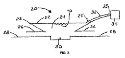
先ず最初に図1及び図2を参照すると、これらの図には創傷治療デバイス20が示してある。このデバイス20は、治療空間24を形成するチャンバ22と、創傷30に被せて患者の皮膚表面28に対してシールされるベース26とを含む。例示の実施例では、チャンバ22は、折り目23を持つベローズ形状を有する。しかしながら、本発明はこれに限定されず、水分及び気体に対して不透過性の可撓性材料で形成されたこの他のチャンバ形状を使用してもよい。デバイス20の形成に用いられる材料を以下に更に詳細に論じる。デバイス20は、円形、正方形、矩形、チューブ状、袋状、エンベロープ状、又は他の形状を使用して、任意の創傷又は身体部分で使用するように設計できる。例えば、肢部に配置するためのチューブ状又はスリーブ状のチャンバを図19に示す。再び図1及び図2を参照すると、患者の通常の動きでチャンバ22が不時に外れたり流体密シールが破れたりしないように十分な接着強度の流体密シールを形成するため、皮膚用の接着剤がベース26の下面に設けられている。こうした目的に対して十分な多くの接着剤が当業者に周知である。
Reference is first made to FIGS. 1 and 2, which illustrate a
チューブ32が、好ましくは、ベース26から上方に間隔が隔てられた位置でチャンバ22に取り付けられており、治療空間24と連通している。チューブ32は、潰れることなくその形状を保持し、創傷流体及び創傷屑を通すことができるような構造を備えている。チューブ32は、チャンバ22に永久的に連結されていてもよいし、チューブ32の取り付け及び取り外しを行うことができるように継手25が設けられていてもよいし、治療空間24に材料又は治療を送出でき、又は治療空間24から材料を除去できる任意の他のデバイスが設けられていてもよい。チューブ32は、チャンバ22の壁で終端してもよいし、壁を通って所定距離延び、治療空間24内で終端してもよい。これにより、チャンバ壁の内面に形成されたチャンネルによって、又はチャンバ壁に形成された折り目によって治療空間24と連通していてもよい。別の変形例として、チューブ32は、ルアー継手でチャンネル22に連結されていてもよい。チューブ32は、液体又は気体が治療空間24から外部環境に漏れないようにチャンバ22に対してシールされる。チューブ32の遠位端は、吸引デバイス34で終端する。吸引デバイス34はポンプであってもよいが、以下に論じるように、これ以外の種類のデバイスを使用してもよい。吸引デバイス34をチューブ32から外したりチューブ32に再取り付けしたりできるように、継手33が設けられていてもよい。
A
図3を参照すると、この図には、チャンバ22に取り付けられており且つチャンネル又は折り目によって治療空間24と連通した第2チューブ35を示す、デバイス20の断面図が示してある。チューブ35の遠位端は、入り口36で終端する。本発明では、連通チューブの数に制限がなく、治療空間24にアクセスするために多数のチューブ及び入り口を設けることができる。図4は、チューブ32の枝部に入り口36が設けられた図1のデバイスを示す。入り口36は、負圧の送出前、送出中、又は送出後に抗菌物質、抗生物質、抗真菌薬、及び鎮痛薬等の治療モダリティを送出するのに使用してもよい。このように、入り口36は、容器又は注射器に取り付けられるように形成されたルアー継手であってもよい。別の態様では、吸引デバイス34と連通した同じチューブ32を通して治療モダリティを送出してもよい。
Referring to FIG. 3, there is shown a cross-sectional view of the
次に図5を参照すると、チャンバ空間24内に延びるチューブ32の端部に多数の穴44が設けられていることを示す。これらの穴44の目的は、気体、液体、創傷流体、創傷屑等をチャンバ空間24からチューブ32内に難なく流入できるようにし、除去できるようにすることである。
Referring now to FIG. 5, it is shown that a number of holes 44 are provided at the end of the
図6を参照すると、チャンバ壁の内面に構造40が形成されていてもよいということが示してある。これらの構造は、表面上に技術的手段によって形成されたエンジニアード構造である。エンジニアード構造40が形成された内面の部分は、添付図面に示すのと異なっていてもよく、好ましくは、内面の大部分にエンジニアード構造40が設けられている。これらのエンジニアード構造は、好ましくは、内面の少なくとも50%を覆っており、更に好ましくは、内面の少なくとも95%を覆っている。これらの構造は、チャンバ空間24内から見た場合に盛り上がっており、チャンバ空間24の内面に対してほぼ垂直な方向でチャンバ空間24内に突出している。これらの構造は、円錐形、角錐形、五角形、六角形、半球形、ドーム形状、ロッド状、側部に丸味がある細長い押縁状、又は側部に角がある細長い押縁状を含むがこれらに限定されない任意の構造を備えていてもよい。これらの構造は、同じ形状で設けられていてもよいし、これらの形状の任意の組み合わせで形成されていてもよい。これらの構造は、同じ大きさで設けられていてもよいし、様々な大きさの任意の組み合わせで形成されていてもよい。構造は、互いから均等に間隔が隔てられていてもよいし、不均等に間隔が隔てられていてもよい。更に、これらの構造は、チャンバ22の表面の一部によって間隔が隔てられていてもよい。これらの構造の、チャンバ壁からチャンバ治療空間24内への突出距離は、好ましくは、0.01mm乃至20mmであり、更に好ましくは1mm乃至1cmである。このような構造間の間隔は、好ましくは、0.01mm乃至5cmである。
Referring to FIG. 6, it is shown that a
エンジニアード構造40は、デバイス20の使用中に創傷表面と干渉する。これらの構造の一つの目的は、チャンバ空間24内に発生した負圧を均等に分配し、この空間内に亘って維持することである。吸引源に繋がったチューブ内に負圧が発生すると、チャンバは創傷組織に更にぴったりと当てられる。デバイス20には、創傷表面に亘って負圧を発生し、分配し、そして維持するための通路を形成し、チャンバの内面と創傷組織との間が完全に接触しないようにするため、エンジニアード表面40が設けられる。このような構造がないと、チャンバ壁が創傷表面と完全に接触してしまう。その結果、負圧を発生し、分配し、そして維持できる空間がなくなってしまう。従って、エンジニアード構造は、好ましくは、半剛性である。「半剛性」という用語は、0.03515kg/cm2 乃至0.1406kg/cm2 (0.5psi乃至2psi)の範囲の負圧が作用した状態で、変形が顕微鏡的レベルでしか生じないということを意味すると理解されるべきである。別の態様では、エンジニアード構造は、構造間の間隔に応じて幾分可撓性であってもよい。更に、これらの構造は、創傷組織が構造間の間隔に入り込むことができる程度を減少し、十分な量の開放空間が維持されるように、技術的手段によって形成されている。
Engineered
これらの構造の追加の目的は、創傷に対する一つの刺激形態として役立ち、顆粒形成組織の形成及び微小な機械的力の増大が含まれるがこれらに限定されない、有用な結果をもたらすことである。このような機械的力は、創傷組織の一部に刺激を提供する。これは、負圧創傷治療の有効性に寄与する要因であると考えられる。以上の議論及び添付図面から、可撓性チャンバは、所定範囲の位置に亘って移動できるということは理解されなければならない。位置の範囲には、エンジニアード表面40が、ベース26が形成するチャンバの開口部から間隔が隔てられた、図1及び図2に示す第1位置が含まれる。位置の範囲には、更に、少なくとも幾つかのエンジニアード表面40がチャンバの開口部に位置決めされた、第2位置が含まれる。第2位置は、好ましくは、エンジニアード表面40が創傷と係合する位置である。
An additional purpose of these structures is to serve as a stimulating form for the wound and provide useful results, including but not limited to the formation of granulated tissue and the increase in micro mechanical forces. Such mechanical force provides stimulation to a portion of the wound tissue. This is considered to be a factor contributing to the effectiveness of negative pressure wound treatment. From the above discussion and the accompanying drawings, it should be understood that the flexible chamber can be moved over a range of positions. The range of positions includes the first position shown in FIGS. 1 and 2 where the engineered
チャンバ壁は、以下に列挙する特徴を持つ任意の適当な医療等級の材料で形成されていてもよい。これらの特徴は、形態一致性、気体不透過性、液体不透過性、形成性、加工性、及び技術的手段による形成性、及び盛り上がったエンジニアード構造の形状、機能、及び有効性を所望の負圧範囲で保持する性能である。更に、材料は、好ましくは低アレルゲン性であり、医療施設に殺菌状態で提供される。例えば、チャンバデバイスは、可撓性で形態一致性のポリウレタン等の材料で形成されていてもよいが、この他の同様の材料を使用してもよい。チャンバは、好ましくは、特別のサイジング、トリミング、又は他のカスタム化作業なしで創傷組織の表面に十分な材料を当てるように設計されている。チャンバは、一層の材料から形成されていてもよく、又は多数の材料層から形成されていてもよく、これらの材料層に構造が技術的手段によって形成される。単層チャンバは、製造中、多数の材料シートから形成されてもよいが、単層チャンバは、多数のシートが結合又は他の態様で互いに連結された状態で医療施設に提供されるということは理解されるべきである。例えば、製造中に個々の立体的形状をチャンバ壁の内面に接着又は結合し、エンジニアード構造を提供してもよい。単層チャンバは、更に、チャンバ壁及びエンジニアード構造の両方を形成する一枚の材料シートから形成されてもよい。別の態様では、材料層が積み重ねられてチャンバを形成した状態で多層チャンバを医療施設に提供する。例えば、チャンバの内部治療空間に面する層は、診療医が全体に平らな材料層(又は全体に平らな層でできた多数のシート)に結合したエンジニアード構造を含む層であってもよい。 The chamber wall may be formed of any suitable medical grade material having the characteristics listed below. These features are desirable for form conformity, gas impermeability, liquid impermeability, formability, processability, and formability by technical means, and the shape, function, and effectiveness of raised engineered structures. The performance is maintained in the negative pressure range. Furthermore, the material is preferably hypoallergenic and is provided in a sterilized condition to the medical facility. For example, the chamber device may be formed of a material such as flexible and conformal polyurethane, but other similar materials may be used. The chamber is preferably designed to apply sufficient material to the surface of the wound tissue without special sizing, trimming or other customization operations. The chamber may be formed from a single layer of material, or may be formed from multiple layers of material, in which structure is formed by technical means. A single-layer chamber may be formed from multiple sheets of material during manufacture, but a single-layer chamber is provided to a medical facility with multiple sheets bonded or otherwise coupled together. Should be understood. For example, individual three-dimensional shapes may be bonded or bonded to the inner surface of the chamber wall during manufacturing to provide an engineered structure. The single layer chamber may further be formed from a single sheet of material that forms both the chamber wall and the engineered structure. In another aspect, a multi-layer chamber is provided to a medical facility with material layers stacked to form a chamber. For example, the layer facing the interior treatment space of the chamber may be a layer comprising an engineered structure bonded by a clinician to a generally flat material layer (or multiple sheets of generally flat layers). .
エンジニアード構造は、エンボス加工、型押し、型成形、形成、結合等の当業者によく知られた技術によって形成されていてもよい。エンボス加工によって構造の形状を材料に形成することによって構造を形成する場合、エンボス加工で形成した構造は、図6に示すように、チャンバの外側に対して凹状をなした状態で残る。エンボス加工で形成した構造は、更に、チャンバ及びベースの壁を形成する単層の材料に形成されていてもよい。これにより、比較的可撓性のチャンバ及び半剛性の構造を単層の材料上に形成する。別の態様では、構造を堅固にする適当な材料でキャビティを充填してもよい。別の変形例として、堅固な構造をチャンバの内面に取り付けてもよい。 The engineered structure may be formed by techniques well known to those skilled in the art, such as embossing, embossing, mold forming, forming, and bonding. When the structure is formed by forming the shape of the structure in the material by embossing, the structure formed by the embossing remains in a concave shape with respect to the outside of the chamber, as shown in FIG. The embossed structure may further be formed in a single layer material that forms the walls of the chamber and base. This forms a relatively flexible chamber and semi-rigid structure on a single layer of material. In another embodiment, the cavities may be filled with a suitable material that will stiffen the structure. As another variation, a rigid structure may be attached to the inner surface of the chamber.
チャンバ壁の内面に設けられた盛り上がった構造は、多くのパターンで形成でき且つ分配できる。例えば、図6は、チャンバ壁の一部の側断面図であり、治療空間24に面する材料の内面に設けられたエンジニアード構造40を示す。これらの構造40は、形状及び大きさが同じであり、互いから均等に位置決めされている。別の例として、図7は、チャンバ空間に突出したエンジニアード構造41及び42を示す側断面図である。構造41は、構造42よりも大きく突出しており、これらの構造は、41−42−41−42の規則的な交互のパターン等で形成されている。更に別の例として、図8は、チャンバ空間に突出したエンジニアード構造43、44、及び45を示す側断面図である。構造43は構造44及び45よりも大きく突出しており、構造44は構造43よりも小さく突出しているが、構造45よりも大きく突出しており、構造45は構造43及び44よりも小さく突出している。これらの構造は、43−45−44−45−43−45−44−45−43の規則的な交互のパターン等で形成されている。図8に示す実施例は、軟質の創傷組織が、盛り上がった構造間の全ての空間に入り込むことを困難にする。負圧の分配並びに流体及び治療の追加、及び創傷からの流体及び材料の除去を可能にするのに十分な量の連続した空間が形成される。更に別の例として、図9aは、盛り上がった押縁の形態のエンジニアード構造47を示す、チャンバ壁の一部の概略図である。エンジニアード構造47は、側面図で見た場合、丸味が付けてあってもよく(図9b参照)、角があってもよく(図9c参照)、又はこれらの組み合わせを備えていてもよい。更に別の例として、図10は、押縁構造47とともに散在するドーム状エンジニアード構造48を示す概略図である。これらのドーム状エンジニアード構造48は、好ましくは、側方から見たときに半球形状であるが、この他の形状も考えられる。
The raised structure provided on the inner surface of the chamber wall can be formed and distributed in many patterns. For example, FIG. 6 is a side cross-sectional view of a portion of a chamber wall showing an engineered
チャンバデバイス内及び創傷の全ての点での負圧の分配及び維持は、盛り上がったエンジニアード構造間に負圧を分配するための通路として所定のチャンネル空間を提供することによって高められる。しかしながら、これらの所定のチャンネル空間は、治療空間24内に流体通路を提供する上では必要とされない。図11は、チャンネル49を形成する二つの平行な線をなして配置された構造47を示す、チャンバ壁の一部の概略図である。図12は、盛り上がったドーム状構造48で形成された二つの平行な線によって形成されたチャンネル49を示す。このようなチャンネルは、放射状、円形状、同心状、又は分枝状等の様々なパターンで形成できる。図13乃至図16は、治療空間24に面するチャンバ22の内面に沿ってチューブ32から延びるチャンネル49のパターンの概略図である。各パターンについて、チャンネル49は、治療空間24に直接開放した空間を形成する。空間は、好ましくは、チャンネル49の全長に亘り、治療空間24に対して開放している。
The distribution and maintenance of negative pressure within the chamber device and at all points of the wound is enhanced by providing a predetermined channel space as a passage for distributing negative pressure between raised engineered structures. However, these predetermined channel spaces are not required to provide a fluid passage in the
チャンバデバイス内及び創傷の全ての点での負圧の分配及び維持は、負圧を分配するための追加のチャンネル空間を形成するためにチャンバ壁で折り目を使用することによっても高めることができる。チャンバ内で負圧を発生したとき、材料は、所定位置に沿って折り畳まれる。図17は、チャンバ壁の折り目に形成されたチャンネル50を示す。チャンネル50は、治療空間24に直接開放した空間を形成する。この空間は、好ましくは、チャンネル50の全長に亘って治療空間24に開放している。このような折り目内のチャンネル空間の量を増加するため、折り目の壁は、このような空間が潰れないようにし、負圧を分配し且つ維持し、液体、気体及び他の材料を通過するための連続的に開放した空間を確保する構造を持つように形成できる。変形例として、図18aは、折り目が全体として潰れることがないようにし、連続したチャンネル空間51を確保するエンジニアード構造52を示す。チャンバ壁の内面に形成された全てのチャンネル空間又は折り目は、負圧をチャンバ内に分配し維持する上での有効性を向上するための手段として、及びチャンバ治療空間から気体、液体、創傷流体、創傷屑、及び他の材料を除去する上での有効性を高めるための手段として機能する。別の例として、図18bは、折り目の向き合った側部に盛り上がったエンジニアード構造52を追加した、図17に示す実施例と同様の実施例を示す。エンジニアード構造52は、その内面全てが、負圧の移動に抗する気密シールを形成する点まで折り目が潰れないように設けられている。しかしながら、内面の幾つか、例えば折り目と隣接した内面は、好ましくは、創傷と接触し、上文中に論じたように刺激を提供する。上述の実施例で説明した折り目は、好ましくは、チャンバ22の表面に型成形又はエンボス加工を施すことによって、所定の領域に形成される。
The distribution and maintenance of negative pressure within the chamber device and at all points of the wound can also be enhanced by using creases in the chamber walls to form additional channel space for distributing negative pressure. When negative pressure is generated in the chamber, the material is folded along a predetermined position. FIG. 17 shows a
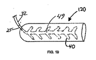
図19は、負圧及び治療物質を送出するための、肢部に被せて配置できるチューブの形態の創傷チャンバデバイス120を示す。創傷チャンバデバイス120は全体に円筒形であり、開放端及び閉鎖端を含む。開放端は、好ましくは、カフ又はカラー(図示せず)によってシールされており、開放端の内面には接着剤が設けられていてもよい。創傷チャンバデバイス120は、チャンバ壁の内面にエンジニアード構造40及びチャンネル49を含む。創傷チャンバデバイス120は、更に、上文中に説明した折り目及びチャンネルを含んでいてもよい。
FIG. 19 shows a
図20に示すように、チャンバ22と吸引デバイス34との間のチューブ32に流体収集器60が位置決めされていてもよい。収集器60は、チャンバ空間24から取り出した流体及び創傷からの屑又は材料を受け取ってこれを最終的に処分するために貯蔵するようになっている。収集器60は、一杯になった収集器を空の収集器と交換するため、チューブ32から取り外すことができる。
As shown in FIG. 20, a
創傷治療デバイスに対する吸引力は、吸引デバイス34によって提供される。吸引デバイス34は、適当なコネクタによってチャンバデバイスに連結したりこれから取り外されるポンプであってもよい。創傷チャンバは、モータ駆動式ポンプとともに使用できるけれども、介護者又は患者が作動する手動デバイスでも有効である。手動デバイスは、その構造の材料に蓄えられたエネルギによって吸引力を提供するスクイズバルブ(squeeze bulb)であってもよい。臨床的に望ましい負圧レベルを発生するため、ばねを選択できる。従って、これらの吸引デバイスが提供する吸引力の量は、スクイズ状態の材料又はばねが発生する力のレベルで決まる。モータ駆動式吸引ポンプとは異なり、手動デバイスは、好ましくは、創傷の治癒に対して悪影響を及ぼす高レベルの吸引力を発生できない。
The suction force for the wound treatment device is provided by the
図21を参照すると、変形のエネルギを蓄える変形自在の材料で形成されたバルブの形態の吸引デバイス61を使用してもよい。チューブ32は、吸引デバイス61の内部と連通している。更に、一方向排気弁62が吸引デバイス61の内部と連通している。使用者が吸引デバイス61を絞ると、デバイス内の空気が排気弁62を通って排出される。吸引デバイス61の変形に使用されたエネルギの一部が、デバイス61を形成する材料に蓄えられ、かくしてデバイス内並びにチューブ32及びチャンバ空間24内に吸引力を維持する。バルブは、一定の力が作用した状態を維持し、臨床的に所望のレベルの負圧をチャンバ空間24内に維持するように選択され、技術的手段によって形成される。創傷30からの流体は、チューブ32を通って吸引デバイス61に流入し、ここに廃棄前に貯蔵される。吸引デバイスが流体で一杯になると、負圧の発生が停止する。かくして、吸引デバイスの流体容量は、電子センサ及び制御装置を必要とすることなく、安全遮断機構として作動する。
Referring to FIG. 21, a
図22は、可撓性側部64及び剛性側部65を含む変形例の吸引デバイス63を示す。圧縮ばね66が吸引デバイス63内に配置されている。チューブ32及び排気弁62の両方が吸引デバイス63の内部と連通している。使用者が剛性側部65を互いに向かって移動すると、ばね66が圧縮され、デバイス内の空気が一方向弁62を通って排出され、かくしてデバイス内並びにチューブ32及びチャンバ空間24内に吸引力を維持する。ばね66は、剛性側部65に一定の力が作用した状態を維持し、臨床的に所望のレベルの負圧をチャンバ空間24内に維持するように選択され、技術的手段によって形成される。創傷30からの流体は、チューブ32を通って吸引デバイス63に流入でき、デバイス63全体を処分する前にここに蓄えられる。この吸引デバイスもまた、流体で一杯になると作動を停止する。
FIG. 22 shows a modified
図23は、ヒンジ73によって結合された剛性側部72及び可撓性側部71を含む変形例の吸引デバイス70を示す。トーションばね74が剛性側部72の内部又は外部のいずれかに取り付けられている。チューブ32及び排気弁62の両方が吸引デバイス70の内部と連通している。使用者が剛性側部72を互いに向かって移動したとき、ばね74が圧縮され、デバイス内の空気が一方向排気弁62を通って放出され、かくしてデバイス並びにチューブ32及びチャンバ空間24内に負圧を維持する。ばね74は、剛性側部72に一定の力が作用した状態を維持し、臨床的に所望のレベルの負圧をチャンバ空間24内に維持するように選択され且つ形成される。創傷30からの流体は、チューブ32を通って吸引デバイス70に流入でき、デバイス全体を処分する前にここに蓄えられる。図24は、トーションばね74を板ばね78に代えた図23のデバイスを示す。
FIG. 23 shows an alternative suction device 70 that includes a
上述の吸引デバイスについて、ひとたび吸引力が発生すると、流体は創傷から吸引デバイスに流れ、ここに集められ、最終的に処分するために貯蔵される。別の態様では、図20に示す流体収集器60等の別体の流体収集器をチャンバと吸引デバイスとの間に位置決めしてもよい。吸引デバイスが拡張してその元の形状に戻ると、吸引が終了する。吸引デバイスは作動し続けるのではなく、取り外して廃棄できる。治療を続行する場合には、新たな吸引デバイスを連結して作動する。
For the suction devices described above, once suction force is generated, fluid flows from the wound to the suction device where it is collected and finally stored for disposal. In another aspect, a separate fluid collector, such as the
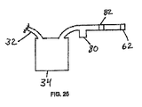
図25は、液体やエアゾールが吸引デバイスから排除されないようにすることを目的として、吸引デバイス34と排気弁62との間に配置したトラップ80及びフィルタ82の断面図である。
FIG. 25 is a cross-sectional view of the
本発明は、臨床的手順に従って様々な負圧レベルで作動するように形成されている。歴史的には、一般的に受け入れられる負圧レベルは、0.03515kg/cm2 乃至0.1406kg/cm2 (0.5psi乃至2psi)である。本発明のデバイスは、この範囲内で有効に作動する。チャンバ材料は、創傷と形状が一致し、エンジニアード構造はそれらの形状及び機能を維持する。しかしながら、チャンバは、比較的高い負圧レベルで作動するように形成されていてもよい。更に、手動式吸引デバイスを使用した場合、デバイスの作動圧力は、一般的に受け入れられる範囲よりも高く、即ちデバイスは吸引の停止前に0kg/cm2 (0psi)に近い圧力で作動することもある。 The present invention is configured to operate at various negative pressure levels according to clinical procedures. Historically, generally accepted negative pressure levels are between 0.03515 kg / cm @ 2 and 0.1406 kg / cm @ 2 (0.5 psi to 2 psi). The device of the present invention operates effectively within this range. The chamber material matches the shape of the wound and the engineered structure maintains their shape and function. However, the chamber may be configured to operate at a relatively high negative pressure level. Further, when using a manual suction device, the operating pressure of the device is generally higher than acceptable, ie the device may operate at a pressure close to 0 kg / cm @ 2 (0 psi) before stopping suction. .
本発明は、好ましくは、負圧を連続的に提供するけれども、実際には、負圧が発生されない期間がある。更に、介護者は、負圧システムを手動で賦勢したり消勢したりすることによって、負圧を断続的に発生するプログラムを提供してもよい。別の態様では、負圧を断続的に発生するため、負圧源を制御してもよい。例えば、モータ駆動式ポンプが負圧源として設けられている場合には、モータは、負圧を断続的に提供するようにプログラムされた制御装置を含んでいてもよい。 Although the present invention preferably provides negative pressure continuously, in practice there is a period during which no negative pressure is generated. Furthermore, the caregiver may provide a program that intermittently generates negative pressure by manually activating and deactivating the negative pressure system. In another aspect, the negative pressure source may be controlled to generate negative pressure intermittently. For example, if a motor driven pump is provided as a negative pressure source, the motor may include a controller programmed to provide negative pressure intermittently.
負圧をチャンバ内及び創傷表面に亘って分配し維持する上での盛り上がったエンジニアード構造の有効性を試験モデルで証明する。動物の死体組織の試料に創傷を形成した。創傷の中央にある組織に圧力センサを設置した。チャンバ内壁に盛り上がったエンジニアード構造が設けられた創傷チャンバデバイスを創傷の周囲の皮膚にシールした。チャンバデバイスから延びるチューブを、所定範囲の負圧を送出できる吸引源に連結した。創傷への負圧の分配に関するデバイスの有効性を確認するため、吸引源で計測した負圧の量を、創傷中央での計測治療と比較する。以下の値が得られた。
吸引源での圧力(mmHg) 創傷での圧力(mmHg)
− 80 −65 (効率81.25%)
−100 −86 (効率86.00%)
−120 −100(効率83.33%)
盛り上がったエンジニアード構造は、変形することなくそれらの形状を維持し、これによってそれらの機能性を保存することが観察された。
The test model demonstrates the effectiveness of the raised engineered structure in distributing and maintaining negative pressure within the chamber and across the wound surface. Wounds were formed on samples of animal cadaver tissue. A pressure sensor was placed in the tissue in the middle of the wound. A wound chamber device provided with a raised engineered structure on the inner wall of the chamber was sealed to the skin surrounding the wound. A tube extending from the chamber device was connected to a suction source capable of delivering a range of negative pressure. To confirm the effectiveness of the device with respect to the delivery of negative pressure to the wound, the amount of negative pressure measured at the suction source is compared to the measured treatment at the center of the wound. The following values were obtained:
Pressure at suction source (mmHg) Pressure at wound (mmHg)
-80-65 (efficiency 81.25%)
-100 -86 (86.00% efficiency)
-120 -100 (efficiency 83.33%)
Swelled engineered structures were observed to maintain their shape without deformation, thereby preserving their functionality.
本発明の作動を以下の場合によって例示する。皮膚全厚(full-thickness skin) 創傷の患者を、手動式吸引ポンプに連結した創傷チャンバ負圧デバイスで治療する。チャンバの内面には、盛り上がった構造がエンボス加工で形成されている。創傷の周囲の領域を、通常の皮膚消毒剤で治療した。チャンバの接着剤ベースから裏打ちを取り外し、チャンバを創傷周囲の通常の皮膚に対してシールする。チューブを変形例のスクイズバルブに連結する。スクイズバルブは、流体用の入口ポート、及びバルブから空気を通過させて放出できる排気ポートを含む。バルブをその最も平らな形態まで絞ることによって、0.1406kg/cm2 (2psi)の負圧をチャンバ内に発生し、維持する。治療を開始してから最初の24時間が経過した後、スクイズバルブがその通常の大きさの約半分まで拡張した。バルブを再び圧縮し、再びその一杯に平らになった形態にする。バルブを追加の12時間に亘ってこのような形態に維持し、12時間の時点でチャンバを取り外す。創傷には健康な顆粒形成組織が見られ、治癒が急速に進行し、瘢痕を小さくする。製造されたデバイスは、創傷又は周囲の皮膚に悪影響を及ぼさない。 The operation of the present invention is illustrated by the following cases. Full-thickness skin Wound patients are treated with a wound chamber negative pressure device connected to a manual suction pump. A raised structure is formed on the inner surface of the chamber by embossing. The area around the wound was treated with a normal skin disinfectant. The backing is removed from the chamber adhesive base and the chamber is sealed against the normal skin around the wound. Connect the tube to the modified squeeze valve. The squeeze valve includes an inlet port for fluid and an exhaust port through which air can be discharged from the valve. A negative pressure of 0.1406 kg / cm 2 (2 psi) is generated and maintained in the chamber by squeezing the valve to its flattened configuration. After the first 24 hours from the start of treatment, the squeeze valve expanded to about half its normal size. The valve is compressed again and brought back to its full flat form. The valve is maintained in this configuration for an additional 12 hours and the chamber is removed at 12 hours. A healthy granulated tissue is found in the wound, healing proceeds rapidly and scarring is reduced. The manufactured device does not adversely affect the wound or surrounding skin.
本発明は、現存の負圧創傷治療システムの欠点の多くをなくす。例えば、本発明のデバイスは、好ましくは、簡単であり且つ軽量である。本発明の幾つかの実施例では、患者は電源やバッテリーパックに拘束されない。システムは、容易に着用でき、そのため、患者の移動性が損なわれない。更に、注文製作の通路及び構造を必要とせずに創傷インターフェース機器を手早く装着できる。デバイスは、好ましくは、接着剤ベースが滑らかであるため、漏れを生じず、高度の制御装置を備えており且つ安全対策が施してある電動ポンプから吸引力を常に加える必要をなくす。組織の内方成長を生じる可能性があり、感染症の潜伏場所となる多孔質創傷挿入体がない。その代わり、チャンバの内面は全体に非孔質であり且つ非付着性であり、創傷組織と相互作用することがない。更に、吸引ポンプは、好ましくは、加えられる吸引力、作動の持続時間、及び創傷流体による収集器の過剰充填を制限する安全策が組み込まれている。 The present invention eliminates many of the disadvantages of existing negative pressure wound treatment systems. For example, the device of the present invention is preferably simple and lightweight. In some embodiments of the invention, the patient is not tied to a power source or battery pack. The system is easy to wear so that patient mobility is not compromised. In addition, the wound interface device can be quickly installed without the need for custom-made passageways and structures. The device preferably has a smooth adhesive base so that it does not leak and eliminates the need to constantly apply suction from an electric pump that is equipped with advanced controls and safety measures. There is no porous wound insert that can result in tissue ingrowth and is a latent site of infection. Instead, the inner surface of the chamber is generally non-porous and non-adherent and does not interact with the wound tissue. Furthermore, the suction pump preferably incorporates safety measures that limit the applied suction force, duration of operation, and overfilling of the collector with wound fluid.
上文中に開示した特定の実施例は、単なる例示であり、本発明は変更されてもよいし、本明細書中の教示の利点を持つ当業者に明らかな様々な等価の方法で実施されてもよい。更に、以下の特許請求の範囲の記載を除き、構造又は図示の設計の詳細に限定しようとするものではない。従って、上文中に開示した特定の実施例を変形し又は変更してもよいということは明らかであり、このような変更は全て、本発明の範囲及び精神に含まれるものと考えられる。従って、以下の特許請求の範囲に記載の事項について保護が求められる。 The specific embodiments disclosed above are merely exemplary, and the invention may be modified and embodied in various equivalent ways apparent to those skilled in the art having the benefit of the teachings herein. Also good. Furthermore, no limitations are intended to the details of construction or the design shown, except as set forth in the claims below. It is therefore evident that the particular embodiments disclosed above may be altered or modified and all such variations are considered within the scope and spirit of the invention. Therefore, protection is required for the matters described in the following claims.
20 創傷治療デバイス
22 チャンバ
23 折り目
24 治療空間
25 継手
26 ベース
28 皮膚表面
30 創傷
32 チューブ
34 吸引デバイス
35 第2チューブ
36 入り口
40 エンジニアード構造
44 穴
20
Claims (38)
内面と、外面と、隔絶された治療空間を形成するシール部分とを含み、可撓性不透過性材料で形成されたチャンバと、
前記チャンバの内面に形成された複数のエンボス加工された構造であって、該複数のエンボス加工された構造は、前記チャンバの外面に対して凹状形状を形成し、該複数のエンボス加工された構造は、前記創傷に直接接触するように形成されており、負圧を通し、前記隔絶された治療空間内に負圧を分配でき且つ維持できる通路を形成するように形成されており、前記チャンバの前記内面から前記治療空間内に突出し、前記通路は全て前記内面と前記創傷との間にある複数のエンボス加工された構造と、
前記チャンバに連結された第1端を持ち、前記隔絶された治療空間への負圧の適用及び治療モダリティの適用からなる群から選択された少なくとも一つを可能にするように前記隔絶された治療空間と流体連通したチューブとを含む、デバイス。 In a device for treating a wound,
A chamber formed of a flexible impermeable material, including an inner surface , an outer surface, and a seal portion that forms an isolated treatment space ;
A plurality of embossed structures formed on the inner surface of the chamber, the plurality of embossed structures forming a concave shape with respect to the outer surface of the chamber, the plurality of embossed structures Is configured to directly contact the wound, and is configured to form a passage through which negative pressure can be passed and distributed and maintained within the isolated treatment space. A plurality of embossed structures projecting from the inner surface into the treatment space, all the passages being between the inner surface and the wound ;
Having a first end coupled to said chamber, said is isolated to allow at least one selected from a negative pressure application and the group consisting of the application of the treatment modalities to the isolated treatment volume treated A device comprising a tube in fluid communication with a space.
前記複数のエンボス加工された構造は、前記チャンバの前記内面にチャンネルを形成する所定のパターンをなして配置されている、デバイス。 The device of claim 1, wherein
The plurality of embossed structures are arranged in a predetermined pattern forming a channel on the inner surface of the chamber.
前記複数のエンボス加工された構造は、前記内面に対してほぼ垂直な方向で前記隔絶された治療空間に突出している、デバイス。 The device of claim 1, wherein
The device wherein the plurality of embossed structures project into the isolated treatment space in a direction substantially perpendicular to the inner surface.
前記複数のエンボス加工された構造の各々は、円錐形、角錐形、五角形、六角形、半球形、ドーム形状、ロッド状、側部に丸味がある細長い押縁状、又は側部に角がある細長い押縁状からなる群から選択された形状を有する、デバイス。 The device of claim 1, wherein
Each of the plurality of embossed structures is conical, pyramidal, pentagonal, hexagonal, hemispherical, dome-shaped, rod-shaped, elongated rim with rounded sides, or elongated with corners on the sides. A device having a shape selected from the group consisting of ledges.
前記チャンバは、一層の材料から形成されている、デバイス。 The device of claim 1, wherein
The device, wherein the chamber is formed from a single layer of material.
前記複数のエンボス加工された構造の各々は半剛性である、デバイス。 The device of claim 5, wherein
The device, wherein each of the plurality of embossed structures is semi-rigid.
前記チャンバの第1開口部を形成するベースを含み、
前記複数のエンボス加工された構造、前記チャンバ、及び前記ベースは一層の材料から形成されている、デバイス。 The device of claim 5, further comprising:
A base forming a first opening of the chamber;
The device wherein the plurality of embossed structures, the chamber, and the base are formed from a single layer of material.
前記チャンバはベローズ形状を有する、デバイス。 The device, wherein the chamber has a bellows shape.
前記チャンバに連結されたベースを含み、前記ベースは接着剤が設けられた第1面を含み、前記ベースは前記チャンバの第1開口部を形成する、デバイス。 A device including a base coupled to the chamber, the base including a first surface provided with an adhesive, the base forming a first opening of the chamber.
前記チューブは、前記チャンバが形成する前記第1開口部から間隔が隔てられた位置で前記チャンバに連結されている、デバイス。 The device, wherein the tube is connected to the chamber at a position spaced from the first opening formed by the chamber.
吸引デバイス、流体トラップ、及び排気ポートを含み、前記吸引デバイスは、前記治療空間、前記流体トラップ、及び前記排気ポートと流体連通しており、前記流体トラップは前記吸引デバイスと前記排気ポートとの間に流動学的に位置決めされている、デバイス。 The device of claim 1, further comprising:
A suction device, a fluid trap, and an exhaust port, wherein the suction device is in fluid communication with the treatment space, the fluid trap, and the exhaust port, and the fluid trap is between the suction device and the exhaust port. A device that is rheologically positioned.
楔形状手動ポンプを含み、前記治療空間は、前記楔形状手動ポンプと流体連通している、デバイス。 The device of claim 1, further comprising:
A device including a wedge-shaped manual pump, wherein the treatment space is in fluid communication with the wedge-shaped manual pump.
前記前記楔形状手動ポンプは、前記前記楔形状手動ポンプを非圧縮位置に押圧するばねを含む、デバイス。 The device of claim 12, wherein
The wedge-shaped manual pump includes a spring that presses the wedge-shaped manual pump into an uncompressed position.
前記チャンバは全体に円筒形であり、肢部の創傷を治療するように形成されている、デバイス。 The device of claim 1, wherein
The device, wherein the chamber is generally cylindrical and is configured to treat a limb wound.
前記創傷に直接接触するように形成されている複数のエンボス加工された構造は、互いに均一に間隔を隔てて位置決めされている、デバイス。 A device wherein a plurality of embossed structures configured to directly contact the wound are positioned evenly spaced from one another.
デバイスは、治癒過程が長期に亘る創傷を治療するように形成されている、デバイス。 The device is configured to treat a wound that has a long healing process.
前記エンボス加工された構造は、内面上に突出部を形成し、外面上に凹部を形成している、デバイス。 The embossed structure forms a protrusion on the inner surface and a recess on the outer surface.
前記チャンバは、形状一致性を有する、デバイス。 The chamber has a shape matching device.
前記創傷に直接接触するように形成されている複数のエンボス加工された構造は、互いに不均一に間隔を隔てて位置決めされている、デバイス。 A device, wherein a plurality of embossed structures configured to directly contact the wound are non-uniformly spaced from one another.
内面と、外面と、を含み、治療空間を形成し、形状一致性不透過性材料で形成されたチャンバと、 A chamber that includes an inner surface and an outer surface, forms a treatment space, and is formed of a shape-matching impermeable material;
前記創傷に直接接触するように形成されており、負圧を通し、前記治療空間内に負圧を分配でき且つ維持できる通路を形成するように形成された複数の半剛性構造であって、該複数の半剛性構造は、前記チャンバの前記内面から前記治療空間内に突出し、前記チャンバの外面に対して凹状形状を形成し、前記通路は全て前記内面と前記創傷との間にある複数の半剛性構造と、 A plurality of semi-rigid structures formed to directly contact the wound and formed to form a passage through which negative pressure can be distributed and maintained within the treatment space; A plurality of semi-rigid structures project into the treatment space from the inner surface of the chamber and form a concave shape with respect to the outer surface of the chamber, and the plurality of semi-rigid structures are all between the inner surface and the wound. Rigid structure,
前記チャンバに連結された第1端を持ち、前記治療空間への負圧の適用及び治療モダリティの適用からなる群から選択された少なくとも一つを可能にするように前記治療空間と流体連通したチューブとを含み、 A tube having a first end connected to the chamber and in fluid communication with the treatment space to allow at least one selected from the group consisting of applying negative pressure to the treatment space and applying a treatment modality Including
前記デバイスは、治癒過程が長期に亘る創傷を治療するように形成されている、デバイス。 The device is configured to treat a wound that has a long healing process.
前記シャンバは、所定範囲の位置に亘って移動可能であり、前記所定範囲の位置は、前記複数の半剛性構造が前記チャンバの第1の開口部から間隔を隔てた配置される第1位置を含み、前記所定範囲の位置は、前記複数の半剛性構造の少なくとも幾つかが、前記チャンバの前記第1の開口部に位置決めされる第2位置を含む、デバイス。 The shank is movable over a predetermined range of positions, the predetermined range of positions being a first position where the plurality of semi-rigid structures are spaced apart from the first opening of the chamber. And the predetermined range of positions includes a second position in which at least some of the plurality of semi-rigid structures are positioned in the first opening of the chamber.
前記複数の半剛性構造は、前記内面の少なくとも95%を覆う、デバイス。 The device wherein the plurality of semi-rigid structures cover at least 95% of the inner surface.
前記創傷に直接接触するように形成されている前記複数の半剛性構造は、互いに均一に間隔を隔てて位置決めされている、デバイス。 The device, wherein the plurality of semi-rigid structures configured to directly contact the wound are uniformly spaced from one another.
前記半剛性構造は、前記チャンバ内にエンボス加工されている、デバイス。 The device, wherein the semi-rigid structure is embossed in the chamber.
前記半剛性構造は、外面上に凹部を形成している、デバイス。 The semi-rigid structure forms a recess on an outer surface.
前記チャンバに結合されたベースをさらに含み、前記ベースは、創傷の周囲をシールし、前記治療空間を隔絶するように形成されているシール部分を含む、デバイス。 The device further comprising a base coupled to the chamber, wherein the base includes a seal portion configured to seal around a wound and isolate the treatment space.
前記シール部分は、接着剤を含む、デバイス。 The device, wherein the seal portion includes an adhesive.
前記創傷に直接接触するように形成されている前記複数の半剛性構造は、互いに不均一に間隔を隔てて位置決めされている、デバイス。 The device, wherein the plurality of semi-rigid structures configured to directly contact the wound are non-uniformly spaced from one another.
創傷に形状一致するのに十分薄い不透過性材料で形成されており、内面と、外面と、を含み、前記内面が内部治療空間を形成する壁と、 A wall that is formed of an impermeable material that is thin enough to conform to the wound and includes an inner surface and an outer surface, the inner surface forming an internal treatment space;
前記壁に結合されたバースであって、該ベースは、前記内部治療空間を取り囲み、表面にシール係合するように配置されたベースと、 A berth coupled to the wall, the base surrounding the internal treatment space and disposed in sealing engagement with a surface;
前記チャンバの内面に形成された複数のエンボス加工された構造であって、該複数のエンボス加工された構造は、前記チャンバの外面に対して凹状形状を形成し、該複数のエンボス加工された構造は、前記創傷に直接接触するように形成されており、負圧を通し、前記隔絶された治療空間内に負圧を分配でき且つ維持できる通路を形成するように形成されており、前記チャンバの前記内面から前記治療空間内に突出し、前記通路は全て前記内面と前記創傷との間にある複数のエンボス加工された構造と、 A plurality of embossed structures formed on the inner surface of the chamber, the plurality of embossed structures forming a concave shape with respect to the outer surface of the chamber, the plurality of embossed structures Is configured to directly contact the wound, and is configured to form a passage through which negative pressure can be passed and distributed and maintained within the isolated treatment space. A plurality of embossed structures projecting from the inner surface into the treatment space, all the passages being between the inner surface and the wound;
前記壁によって支持され、前記治療空間への負圧の適用及び治療モダリティの適用からなる群から選択された少なくとも一つを可能にするように前記治療空間と流体連通した入り口とを含む、デバイス。 A device comprising an inlet supported by the wall and in fluid communication with the treatment space to allow at least one selected from the group consisting of applying negative pressure to the treatment space and applying a treatment modality.
前記ベースは、前記複数のエンボス加工された構造から間隔を隔てて配置されている、 The base is spaced apart from the plurality of embossed structures;
デバイス。device.
前記チャンバはベローズ形状を有する、デバイス。 The device, wherein the chamber has a bellows shape.
前記複数のエンボス加工された構造は、一層の材料から形成されている、デバイス。 The device wherein the plurality of embossed structures are formed from a single layer of material.
デバイスは、治癒過程が長期に亘る創傷を治療するように形成されている、デバイス。 The device is configured to treat a wound that has a long healing process.
前記エンボス加工された構造は、内面上に突出部を形成し、外面上に凹部を形成している、デバイス。 The embossed structure forms a protrusion on the inner surface and a recess on the outer surface.
内面と、外面と、隔絶された治療空間を形成するシール部分とを含み、可撓性不透過性材料で形成されたチャンバと、 A chamber formed of a flexible impermeable material, including an inner surface, an outer surface, and a seal portion that forms an isolated treatment space;
前記チャンバの内面に形成された複数のエンボス加工された構造であって、該複数のエンボス加工された構造は、前記チャンバの外面に対して凹状形状を形成し、該複数のエンボス加工された構造は、前記創傷に直接接触するように形成されており、負圧を通し、前記隔絶された治療空間内に負圧を分配でき且つ維持できる通路を形成するように形成されており、前記チャンバの前記内面から前記治療空間内に突出し、前記通路は全て前記内面と前記創傷との間にある複数のエンボス加工された構造と、 A plurality of embossed structures formed on the inner surface of the chamber, the plurality of embossed structures forming a concave shape with respect to the outer surface of the chamber, the plurality of embossed structures Is configured to directly contact the wound, and is configured to form a passage through which negative pressure can be passed and distributed and maintained within the isolated treatment space. A plurality of embossed structures projecting from the inner surface into the treatment space, all the passages being between the inner surface and the wound;
前記チャンバに連結された第1端を持ち、前記隔絶された治療空間への負圧の適用及び治療モダリティの適用からなる群から選択された少なくとも一つを可能にするように前記隔絶された治療空間と流体連通したチューブとから本質的になる、デバイス。 The isolated treatment having a first end coupled to the chamber and allowing at least one selected from the group consisting of applying negative pressure to the isolated treatment space and applying a treatment modality A device consisting essentially of a tube in fluid communication with a space.
創傷に形状一致するのに十分薄い不透過性材料で形成されており、内面と、外面と、を含み、前記内面が内部治療空間を形成する壁と、 A wall that is formed of an impermeable material that is thin enough to conform to the wound and includes an inner surface and an outer surface, the inner surface forming an internal treatment space;
前記壁に結合されたバースであって、該ベースは、前記内部治療空間を取り囲み、表面にシール係合するように配置されたベースと、 A berth coupled to the wall, the base surrounding the internal treatment space and disposed in sealing engagement with a surface;
前記チャンバの内面に形成された複数のエンボス加工された構造であって、該複数のエンボス加工された構造は、前記チャンバの外面に対して凹状形状を形成し、該複数のエンボス加工された構造は、前記創傷に直接接触するように形成されており、負圧を通し、前記隔絶された治療空間内に負圧を分配でき且つ維持できる通路を形成するように形成されており、前記チャンバの前記内面から前記治療空間内に突出し、前記通路は全て前記内面と前記創傷との間にある複数のエンボス加工された構造と、 A plurality of embossed structures formed on the inner surface of the chamber, the plurality of embossed structures forming a concave shape with respect to the outer surface of the chamber, the plurality of embossed structures Is configured to directly contact the wound, and is configured to form a passage through which negative pressure can be passed and distributed and maintained within the isolated treatment space. A plurality of embossed structures projecting from the inner surface into the treatment space, all the passages being between the inner surface and the wound;
前記壁によって支持され、前記治療空間への負圧の適用及び治療モダリティの適用からなる群から選択された少なくとも一つを可能にするように前記治療空間と流体連通した入り口とから本質的になる、デバイス。 Consisting essentially of an inlet supported by the wall and in fluid communication with the treatment space to allow at least one selected from the group consisting of applying negative pressure to the treatment space and applying a treatment modality ,device.
Applications Claiming Priority (3)
| Application Number | Priority Date | Filing Date | Title |
|---|---|---|---|
| US93159907P | 2007-05-24 | 2007-05-24 | |
| US60/931,599 | 2007-05-24 | ||
| PCT/US2008/064897 WO2008154158A2 (en) | 2007-05-24 | 2008-05-27 | Woundtreatment device employing negative pressure |
Related Child Applications (1)
| Application Number | Title | Priority Date | Filing Date |
|---|---|---|---|
| JP2014220515A Division JP6334364B2 (en) | 2007-05-24 | 2014-10-29 | Wound treatment device using negative pressure |
Publications (3)
| Publication Number | Publication Date |
|---|---|
| JP2010527713A JP2010527713A (en) | 2010-08-19 |
| JP2010527713A5 JP2010527713A5 (en) | 2011-07-14 |
| JP5642539B2 true JP5642539B2 (en) | 2014-12-17 |
Family
ID=40130427
Family Applications (2)
| Application Number | Title | Priority Date | Filing Date |
|---|---|---|---|
| JP2010509587A Active JP5642539B2 (en) | 2007-05-24 | 2008-05-27 | Wound treatment device using negative pressure |
| JP2014220515A Active JP6334364B2 (en) | 2007-05-24 | 2014-10-29 | Wound treatment device using negative pressure |
Family Applications After (1)
| Application Number | Title | Priority Date | Filing Date |
|---|---|---|---|
| JP2014220515A Active JP6334364B2 (en) | 2007-05-24 | 2014-10-29 | Wound treatment device using negative pressure |
Country Status (8)
| Country | Link |
|---|---|
| US (6) | US8632523B2 (en) |
| EP (1) | EP2157948B1 (en) |
| JP (2) | JP5642539B2 (en) |
| CN (2) | CN104014070B (en) |
| AU (2) | AU2008262140B2 (en) |
| CA (1) | CA2688167C (en) |
| ES (1) | ES2625463T3 (en) |
| WO (1) | WO2008154158A2 (en) |
Families Citing this family (120)
| Publication number | Priority date | Publication date | Assignee | Title |
|---|---|---|---|---|
| US9820888B2 (en) | 2006-09-26 | 2017-11-21 | Smith & Nephew, Inc. | Wound dressing |
| US8641691B2 (en) | 2006-09-28 | 2014-02-04 | Smith & Nephew, Inc. | Portable wound therapy system |
| US11511094B2 (en) | 2006-11-21 | 2022-11-29 | Mark R. Moore | Apparatus and method for deploying a surgical preparation |
| WO2008154158A2 (en) * | 2007-05-24 | 2008-12-18 | Applied Tissue Technologies Llc | Woundtreatment device employing negative pressure |
| CN101896140B (en) | 2007-10-10 | 2014-01-08 | 韦克福里斯特大学健康科学院 | Devices and methods for treating spinal cord tissue |
| GB0723855D0 (en) | 2007-12-06 | 2008-01-16 | Smith & Nephew | Apparatus and method for wound volume measurement |
| GB2455962A (en) | 2007-12-24 | 2009-07-01 | Ethicon Inc | Reinforced adhesive backing sheet, for plaster |
| RU2481089C2 (en) | 2008-03-05 | 2013-05-10 | КейСиАй Лайсензинг Инк. | Bandage and method of applying lower pressure to tissue section and collection and storage of flowing medium from tissue section |
| US9033942B2 (en) | 2008-03-07 | 2015-05-19 | Smith & Nephew, Inc. | Wound dressing port and associated wound dressing |
| GB0804654D0 (en) | 2008-03-13 | 2008-04-16 | Smith & Nephew | Vacuum closure device |
| JP6005358B2 (en) | 2008-07-11 | 2016-10-12 | ケーシーアイ ライセンシング インコーポレイテッド | Manual decompression system to treat wounds |
| CA3004987A1 (en) | 2008-07-18 | 2010-01-21 | Wake Forest University Health Sciences | Apparatus and method for cardiac tissue modulation by topical application of vacuum to minimize cell death and damage |
| GB0902368D0 (en) | 2009-02-13 | 2009-04-01 | Smith & Nephew | Wound packing |
| US20100324516A1 (en) | 2009-06-18 | 2010-12-23 | Tyco Healthcare Group Lp | Apparatus for Vacuum Bridging and/or Exudate Collection |
| DE102009031992A1 (en) * | 2009-07-06 | 2011-01-13 | Paul Hartmann Ag | Device for negative pressure therapy of wounds |
| DK2515961T3 (en) | 2009-12-22 | 2019-07-15 | Smith & Nephew Inc | APPARATUS AND METHODS FOR NEGATIVE PRESSURE WOUND THERAPY |
| US8814842B2 (en) | 2010-03-16 | 2014-08-26 | Kci Licensing, Inc. | Delivery-and-fluid-storage bridges for use with reduced-pressure systems |
| US9358158B2 (en) | 2010-03-16 | 2016-06-07 | Kci Licensing, Inc. | Patterned neo-epithelialization dressings, systems, and methods |
| USRE48117E1 (en) | 2010-05-07 | 2020-07-28 | Smith & Nephew, Inc. | Apparatuses and methods for negative pressure wound therapy |
| GB201015656D0 (en) | 2010-09-20 | 2010-10-27 | Smith & Nephew | Pressure control apparatus |
| WO2012087376A1 (en) | 2010-12-22 | 2012-06-28 | Smith & Nephew, Inc. | Apparatuses and methods for negative pressure wound therapy |
| USD714433S1 (en) | 2010-12-22 | 2014-09-30 | Smith & Nephew, Inc. | Suction adapter |
| GB2488749A (en) | 2011-01-31 | 2012-09-12 | Systagenix Wound Man Ip Co Bv | Laminated silicone coated wound dressing |
| EP3932327A1 (en) | 2011-02-04 | 2022-01-05 | University Of Massachusetts | Negative pressure wound closure device |
| US9421132B2 (en) | 2011-02-04 | 2016-08-23 | University Of Massachusetts | Negative pressure wound closure device |
| GB201106491D0 (en) | 2011-04-15 | 2011-06-01 | Systagenix Wound Man Ip Co Bv | Patterened silicone coating |
| US9597484B2 (en) | 2011-04-15 | 2017-03-21 | University Of Massachusetts | Surgical cavity drainage and closure system |
| EP2567681B1 (en) * | 2011-09-09 | 2014-11-12 | Paul Hartmann AG | Wound dressing for the abdominal area |
| CN104114136A (en) * | 2011-09-30 | 2014-10-22 | 艾克西根特技术有限公司 | Electrokinetic pump based wound treatment system and methods |
| US9084845B2 (en) | 2011-11-02 | 2015-07-21 | Smith & Nephew Plc | Reduced pressure therapy apparatuses and methods of using same |
| EP2786793B1 (en) * | 2011-12-01 | 2017-10-18 | Kabushiki Kaisha Toshiba, Inc. | Carbon dioxide recovery device, carbon dioxide recovery method, and amine compound recovery method |
| US10940047B2 (en) | 2011-12-16 | 2021-03-09 | Kci Licensing, Inc. | Sealing systems and methods employing a hybrid switchable drape |
| US9861532B2 (en) | 2011-12-16 | 2018-01-09 | Kci Licensing, Inc. | Releasable medical drapes |
| US10695471B2 (en) * | 2012-02-13 | 2020-06-30 | Phase One Health, Llc | Wound dressing apparatus |
| WO2013154780A1 (en) | 2012-04-12 | 2013-10-17 | Wake Forest University Health Sciences | Design of a conduit for peripheral nerve replacement |
| AU2013291693B2 (en) | 2012-05-22 | 2018-03-01 | Smith & Nephew Plc | Wound closure device |
| CA2874392A1 (en) | 2012-05-22 | 2013-11-28 | Smith & Nephew Plc | Apparatuses and methods for wound therapy |
| EP3470029A1 (en) | 2012-05-24 | 2019-04-17 | Smith & Nephew, Inc. | Devices for treating and closing wounds with negative pressure |
| BR112015000890A2 (en) | 2012-07-16 | 2017-06-27 | Smith & Nephew Inc | negative pressure wound closure device |
| EP2911708A4 (en) | 2012-10-26 | 2016-06-22 | Univ Wake Forest Health Sciences | Novel nanofiber-based graft for heart valve replacement and methods of using the same |
| EP3669842B1 (en) | 2012-11-16 | 2023-09-27 | 3M Innovative Properties Company | Medical drape with pattern adhesive layers |
| GB201222770D0 (en) | 2012-12-18 | 2013-01-30 | Systagenix Wound Man Ip Co Bv | Wound dressing with adhesive margin |
| WO2014103581A1 (en) * | 2012-12-25 | 2014-07-03 | 扶桑薬品工業株式会社 | Hemostatic agent applicator |
| US20140207027A1 (en) * | 2013-01-24 | 2014-07-24 | The Cleveland Clinic Foundation | Wound cover apparatus and method |
| JP6407954B2 (en) | 2013-03-13 | 2018-10-17 | スミス アンド ネフュー インコーポレイテッド | Negative pressure wound closure device and system and method of use in wound treatment with negative pressure |
| US9283118B2 (en) | 2013-03-14 | 2016-03-15 | Kci Licensing, Inc. | Absorbent dressing with hybrid drape |
| EP2968015B1 (en) | 2013-03-14 | 2018-05-16 | Smith & Nephew PLC | Compressible wound fillers and systems and methods of use in treating wounds with negative pressure |
| US20160030722A1 (en) * | 2013-03-15 | 2016-02-04 | The General Hospital Corporation | Method and apparatus for wound dressing |
| EP3021806B1 (en) | 2013-07-16 | 2018-01-31 | Smith & Nephew PLC | Apparatus for wound therapy |
| EP3578209B1 (en) | 2013-08-26 | 2023-12-20 | 3M Innovative Properties Company | Dressing interface with moisture controlling feature and sealing function |
| CA2926470C (en) | 2013-10-21 | 2023-03-14 | Smith & Nephew, Inc. | Negative pressure wound closure device |
| US10946124B2 (en) | 2013-10-28 | 2021-03-16 | Kci Licensing, Inc. | Hybrid sealing tape |
| CN110652396B (en) | 2013-10-30 | 2021-11-23 | 3M创新知识产权公司 | Dressing with perforations of different sizes |
| EP3744361A1 (en) | 2013-10-30 | 2020-12-02 | KCI Licensing, Inc. | Absorbent conduit and system |
| WO2015065612A1 (en) | 2013-10-30 | 2015-05-07 | Kci Licensing, Inc. | Condensate absorbing and dissipating system |
| WO2015065616A1 (en) | 2013-10-30 | 2015-05-07 | Kci Licensing, Inc. | Dressing with sealing and retention intereface |
| CN106456376B (en) | 2014-01-21 | 2020-12-15 | 史密夫及内修公开有限公司 | Wound treatment device |
| MX2016009477A (en) | 2014-01-21 | 2016-10-13 | Smith & Nephew | Collapsible dressing for negative pressure wound treatment. |
| EP3110379B1 (en) | 2014-02-28 | 2019-04-03 | KCI Licensing, Inc. | Hybrid drape having a gel-coated perforated mesh |
| US11026844B2 (en) | 2014-03-03 | 2021-06-08 | Kci Licensing, Inc. | Low profile flexible pressure transmission conduit |
| US10531977B2 (en) | 2014-04-17 | 2020-01-14 | Coloplast A/S | Thermoresponsive skin barrier appliances |
| US10406266B2 (en) | 2014-05-02 | 2019-09-10 | Kci Licensing, Inc. | Fluid storage devices, systems, and methods |
| EP3281616B1 (en) | 2014-06-05 | 2020-01-01 | KCI Licensing, Inc. | Dressing with fluid acquisition and distribution characteristics |
| US10398604B2 (en) | 2014-12-17 | 2019-09-03 | Kci Licensing, Inc. | Dressing with offloading capability |
| US11439539B2 (en) | 2015-04-29 | 2022-09-13 | University Of Massachusetts | Negative pressure wound closure device |
| WO2016182977A1 (en) | 2015-05-08 | 2016-11-17 | Kci Licensing, Inc. | Low acuity dressing with integral pump |
| EP3741335B1 (en) | 2015-09-01 | 2023-05-24 | KCI Licensing, Inc. | Dressing with increased apposition force |
| EP3349807B1 (en) | 2015-09-17 | 2021-02-24 | 3M Innovative Properties Company | Hybrid silicone and acrylic adhesive cover for use with wound treatment |
| US10575991B2 (en) | 2015-12-15 | 2020-03-03 | University Of Massachusetts | Negative pressure wound closure devices and methods |
| US11471586B2 (en) | 2015-12-15 | 2022-10-18 | University Of Massachusetts | Negative pressure wound closure devices and methods |
| US10814049B2 (en) | 2015-12-15 | 2020-10-27 | University Of Massachusetts | Negative pressure wound closure devices and methods |
| CA3009878A1 (en) | 2015-12-30 | 2017-07-06 | Smith & Nephew Plc | Negative pressure wound therapy apparatus |
| BR112019000301A2 (en) | 2016-07-08 | 2019-04-16 | Convatec Technologies Inc. | flexible negative pressure system |
| EP3506865B1 (en) | 2016-08-30 | 2021-10-06 | Smith & Nephew plc | Systems for applying reduced pressure therapy |
| JP6361844B1 (en) * | 2016-09-23 | 2018-07-25 | 株式会社村田製作所 | Negative pressure closure therapy device |
| EP3518847B1 (en) | 2016-09-27 | 2023-03-01 | Smith & Nephew plc | Wound closure devices with dissolvable portions |
| EP3534856A1 (en) | 2016-11-02 | 2019-09-11 | Smith & Nephew, Inc | Wound closure devices |
| CN110612076A (en) * | 2016-12-22 | 2019-12-24 | 应用纸巾技术有限公司 | Apparatus and method for wound treatment |
| CN110997028B (en) | 2017-02-22 | 2022-12-30 | 康奈尔大学 | Mechanical vacuum dressing for mechanical management, protection and aspiration of small incision wounds |
| WO2018231815A2 (en) * | 2017-06-12 | 2018-12-20 | Kci Licensing, Inc. | Fabric wound filler |
| WO2018229010A1 (en) | 2017-06-13 | 2018-12-20 | Smith & Nephew Plc | Collapsible structure and method of use |
| CN110662516B (en) | 2017-06-13 | 2022-02-22 | 史密夫及内修公开有限公司 | Wound closure devices and methods of use |
| WO2018231874A1 (en) | 2017-06-14 | 2018-12-20 | Smith & Nephew, Inc. | Control of wound closure and fluid removal management in wound therapy |
| US11724020B2 (en) | 2017-06-14 | 2023-08-15 | Smith & Nephew Plc | Collapsible sheet for wound closure and method of use |
| EP3638170B1 (en) | 2017-06-14 | 2024-03-13 | Smith & Nephew PLC | Collapsible structure for wound closure and method of use |
| WO2018231878A1 (en) | 2017-06-14 | 2018-12-20 | Smith & Nephew, Inc. | Fluid removal management and control of wound closure in wound therapy |
| WO2019020544A1 (en) | 2017-07-27 | 2019-01-31 | Smith & Nephew Plc | Customizable wound closure device and method of use |
| US11590030B2 (en) | 2017-08-07 | 2023-02-28 | Smith & Nephew Plc | Wound closure device with protective layer and method of use |
| WO2019042790A1 (en) | 2017-08-29 | 2019-03-07 | Smith & Nephew Plc | Systems and methods for monitoring wound closure |
| EP3720518A4 (en) | 2017-12-06 | 2021-09-15 | Cornell University | Manually-operated negative pressure wound therapy (npwt) bandage with improved pump efficiency, automatic pressure indicator and automatic pressure limiter |
| EP4245273A3 (en) | 2017-12-22 | 2023-11-08 | Coloplast A/S | Base plate and sensor assembly of an ostomy system having a leakage sensor |
| DK3729456T3 (en) | 2017-12-22 | 2022-03-07 | Coloplast As | MONITORING DEVICE FOR AN OSTOMY SYSTEM AND ASSOCIATED METHOD FOR OPERATING A MONITORING DEVICE |
| US11707376B2 (en) | 2017-12-22 | 2023-07-25 | Coloplast A/S | Base plate for a medical appliance and a sensor assembly part for a base plate and a method for manufacturing a base plate and sensor assembly part |
| US11612508B2 (en) | 2017-12-22 | 2023-03-28 | Coloplast A/S | Sensor assembly part for a medical appliance and a method for manufacturing a sensor assembly part |
| US10500084B2 (en) | 2017-12-22 | 2019-12-10 | Coloplast A/S | Accessory devices of an ostomy system, and related methods for communicating leakage state |
| WO2019120442A1 (en) | 2017-12-22 | 2019-06-27 | Coloplast A/S | Sensor assembly part and a base plate for an ostomy appliance and a device for connecting to a base plate or a sensor assembly part |
| EP3729453A1 (en) | 2017-12-22 | 2020-10-28 | Coloplast A/S | Calibration methods for ostomy appliance tools |
| AU2018391395A1 (en) | 2017-12-22 | 2020-07-02 | Coloplast A/S | Base plate for an ostomy appliance, a monitor device and a system for an ostomy appliance |
| US10799385B2 (en) | 2017-12-22 | 2020-10-13 | Coloplast A/S | Ostomy appliance with layered base plate |
| LT3727219T (en) | 2017-12-22 | 2023-09-11 | Coloplast A/S | Moisture detecting base plate for an ostomy appliance and a system for determining moisture propagation in a base plate and/or a sensor assembly part |
| JP7348184B2 (en) * | 2017-12-22 | 2023-09-20 | コロプラスト アクティーゼルスカブ | Hinged joint for ostomy base plate and sensor assembly parts |
| US11590015B2 (en) | 2017-12-22 | 2023-02-28 | Coloplast A/S | Sensor assembly part and a base plate for a medical appliance and a method for manufacturing a sensor assembly part and a base plate |
| KR20200103008A (en) | 2017-12-22 | 2020-09-01 | 컬러플라스트 에이/에스 | Leakage device with optional sensor point and associated methods |
| US10849781B2 (en) | 2017-12-22 | 2020-12-01 | Coloplast A/S | Base plate for an ostomy appliance |
| WO2019120437A1 (en) | 2017-12-22 | 2019-06-27 | Coloplast A/S | 2017118-wo |
| WO2019120425A1 (en) | 2017-12-22 | 2019-06-27 | Coloplast A/S | Ostomy appliance system, monitor device, and method of monitoring an ostomy appliance |
| EP3727241A1 (en) | 2017-12-22 | 2020-10-28 | Coloplast A/S | Data collection schemes for an ostomy appliance and related methods |
| WO2019120444A1 (en) | 2017-12-22 | 2019-06-27 | Coloplast A/S | A monitor device of an ostomy system having a connector for coupling to both a base plate and an accessory device |
| EP3727247B1 (en) | 2017-12-22 | 2022-04-20 | Coloplast A/S | Tools and methods for placing an ostomy appliance on a user |
| WO2019120443A1 (en) | 2017-12-22 | 2019-06-27 | Coloplast A/S | Sensor assembly part and a base plate for an ostomy appliance and a method for manufacturing a base plate or a sensor assembly part |
| WO2019161861A1 (en) | 2018-02-20 | 2019-08-29 | Coloplast A/S | Sensor assembly part and a base plate for an ostomy appliance and a device for connecting to a base plate and/or a sensor assembly part |
| GB201811449D0 (en) | 2018-07-12 | 2018-08-29 | Smith & Nephew | Apparatuses and methods for negative pressure wound therapy |
| US11612512B2 (en) | 2019-01-31 | 2023-03-28 | Coloplast A/S | Moisture detecting base plate for an ostomy appliance and a system for determining moisture propagation in a base plate and/or a sensor assembly part |
| US20220176032A1 (en) * | 2019-03-29 | 2022-06-09 | Kci Licensing, Inc. | Dressing With Integrated Pump And Releasably Coupled Pump Actuator |
| CN110522419B (en) * | 2019-09-03 | 2021-11-02 | 苏州元禾医疗器械有限公司 | Wound repair degree detection device and manufacturing method thereof |
| US11696962B2 (en) | 2019-10-16 | 2023-07-11 | Mark R. Moore | Apparatus and method for deploying a preoperative skin disinfection device with integrated drape |
| US20230079448A1 (en) * | 2020-01-10 | 2023-03-16 | Applied Tissue Technologies Llc | Devices and methods for negative pressure therapy |
| US20220008632A1 (en) * | 2020-07-13 | 2022-01-13 | Wellness Allied Inc | Cupping auxiliary consumable, cupping kit, and cupping method |
| US20230030893A1 (en) | 2021-07-29 | 2023-02-02 | Critical Innovations, LLC | Wound treatment device |
| CN115607758B (en) * | 2022-12-01 | 2023-04-04 | 中国医学科学院北京协和医院 | Drainage leakage collecting mechanism and drainage tube device |
Family Cites Families (47)
| Publication number | Priority date | Publication date | Assignee | Title |
|---|---|---|---|---|
| US2283089A (en) * | 1941-05-29 | 1942-05-12 | Blackhawk Mfg Co | Hydraulic wedge assembly |
| JPS5122888B2 (en) | 1971-12-07 | 1976-07-13 | ||
| JPS5122888A (en) | 1974-08-20 | 1976-02-23 | ||
| US4469092A (en) | 1982-09-27 | 1984-09-04 | Marshall Walter D | Scalp stimulating system |
| EP0300621B1 (en) * | 1987-06-22 | 1990-12-27 | Takeda Chemical Industries, Ltd. | Suction equipment for medical operation |
| EP0505478B1 (en) * | 1989-12-14 | 1996-11-27 | Elof Eriksson | A treatment system for wounds and other disorders |
| US5312385A (en) * | 1991-10-09 | 1994-05-17 | University Of Pittsburgh | Device for protected pulse irrigation |
| US7198046B1 (en) * | 1991-11-14 | 2007-04-03 | Wake Forest University Health Sciences | Wound treatment employing reduced pressure |
| US5636643A (en) * | 1991-11-14 | 1997-06-10 | Wake Forest University | Wound treatment employing reduced pressure |
| US5807290A (en) * | 1992-05-29 | 1998-09-15 | South Glamorgan Health Authority | Inflatable supports |
| US5447504A (en) * | 1993-05-03 | 1995-09-05 | Baker; Gregg R. | Misting apparatus for the treatment of injured areas and method therefor |
| US5437602A (en) * | 1993-08-13 | 1995-08-01 | Atm Wound Management, Inc. | Isolator bag for therapeutic treatments of human limbs |
| US5437651A (en) * | 1993-09-01 | 1995-08-01 | Research Medical, Inc. | Medical suction apparatus |
| US5527265A (en) * | 1994-08-16 | 1996-06-18 | Mckeel; William H. | Orthopedic airflow cast pad and method |
| WO1996034638A1 (en) * | 1995-05-02 | 1996-11-07 | Medela, Inc. | Foot-powered breastmilk pump with removable piston pump |
| DE19517699C2 (en) * | 1995-05-13 | 1999-11-04 | Wilhelm Fleischmann | Device for vacuum sealing a wound |
| US5605534A (en) * | 1995-12-26 | 1997-02-25 | Hutchison; Jeffrey W. | Shower guard for IV site |
| US6053882A (en) * | 1996-08-15 | 2000-04-25 | Johansen; Jan S. | Cast ventilation sleeve |
| US6290685B1 (en) * | 1998-06-18 | 2001-09-18 | 3M Innovative Properties Company | Microchanneled active fluid transport devices |
| GB9719520D0 (en) * | 1997-09-12 | 1997-11-19 | Kci Medical Ltd | Surgical drape and suction heads for wound treatment |
| US7273054B2 (en) | 1997-09-12 | 2007-09-25 | Kci Licensing, Inc. | Surgical drape and head for wound treatment |
| US6458109B1 (en) * | 1998-08-07 | 2002-10-01 | Hill-Rom Services, Inc. | Wound treatment apparatus |
| GB2348136B (en) | 1999-03-24 | 2003-06-04 | Johnson & Johnson Medical Ltd | Wound dressings having low adherency |
| GB9926538D0 (en) | 1999-11-09 | 2000-01-12 | Kci Medical Ltd | Multi-lumen connector |
| HUP0500055A2 (en) * | 1999-11-29 | 2005-07-28 | Hill-Rom Services, Inc. | Wound treatment apparatus |
| US6824533B2 (en) * | 2000-11-29 | 2004-11-30 | Hill-Rom Services, Inc. | Wound treatment apparatus |
| JP2001243955A (en) * | 1999-12-28 | 2001-09-07 | Wilson Greatbatch Ltd | Preparation of mixed metal oxide cathode active material by continuous resolution chemical reaction |
| US7356504B2 (en) * | 2000-05-01 | 2008-04-08 | The Olsen Group | Methods for determining value at risk |
| US6855135B2 (en) * | 2000-11-29 | 2005-02-15 | Hill-Rom Services, Inc. | Vacuum therapy and cleansing dressing for wounds |
| US6685681B2 (en) * | 2000-11-29 | 2004-02-03 | Hill-Rom Services, Inc. | Vacuum therapy and cleansing dressing for wounds |
| GB0115054D0 (en) | 2001-06-20 | 2001-08-15 | Recuperatio Ltd | Fluid transfer device |
| US7004915B2 (en) | 2001-08-24 | 2006-02-28 | Kci Licensing, Inc. | Negative pressure assisted tissue treatment system |
| ITRM20010669A1 (en) * | 2001-11-09 | 2003-05-09 | Optikon 2000 Spa | SUCTION INFUSION BOX (I / A) WITH SUCTION SYSTEM BOTH VIA PERISTALTIC PUMP OR OTHERWISE VOLUMETRIC THAN USING PR PUMP |
| CA2468912A1 (en) * | 2001-12-26 | 2003-07-17 | Hill-Rom Services, Inc. | Vented vacuum bandage and method |
| US7520872B2 (en) * | 2002-09-13 | 2009-04-21 | Neogen Technologies, Inc. | Closed wound drainage system |
| US7815616B2 (en) * | 2002-09-16 | 2010-10-19 | Boehringer Technologies, L.P. | Device for treating a wound |
| GB0325126D0 (en) | 2003-10-28 | 2003-12-03 | Smith & Nephew | Apparatus with heat |
| US7128735B2 (en) * | 2004-01-02 | 2006-10-31 | Richard Scott Weston | Reduced pressure wound treatment appliance |
| US7776028B2 (en) * | 2004-04-05 | 2010-08-17 | Bluesky Medical Group Incorporated | Adjustable overlay reduced pressure wound treatment system |
| US7884258B2 (en) * | 2004-04-13 | 2011-02-08 | Boehringer Technologies, L.P. | Wound contact device |
| GB0508529D0 (en) * | 2005-04-27 | 2005-06-01 | Smith & Nephew | Sai with microstress |
| CA2567278A1 (en) * | 2004-05-17 | 2005-12-08 | Applied Tissue Technologies, Llc | Wound chamber with remote access portal |
| US7612247B2 (en) * | 2004-09-29 | 2009-11-03 | Oyaski Michael F | Wound alternative treatment system |
| US20060216171A1 (en) * | 2005-03-23 | 2006-09-28 | Alltrade Tools Llc | Hand held pump |
| AU2006263650B2 (en) * | 2005-06-29 | 2012-03-15 | Applied Tissue Technologies, Llc | Wound chamber for limb |
| BRPI0715320A2 (en) * | 2006-10-13 | 2013-07-09 | Kci Licensing Inc | manually activated reduced pressure treatment system, activating method of a reduced pressure treatment pump and low profile reduced pressure treatment system |
| WO2008154158A2 (en) * | 2007-05-24 | 2008-12-18 | Applied Tissue Technologies Llc | Woundtreatment device employing negative pressure |
-
2008
- 2008-05-27 WO PCT/US2008/064897 patent/WO2008154158A2/en active Application Filing
- 2008-05-27 CA CA2688167A patent/CA2688167C/en active Active
- 2008-05-27 US US12/601,394 patent/US8632523B2/en active Active
- 2008-05-27 EP EP08756312.8A patent/EP2157948B1/en active Active
- 2008-05-27 CN CN201410255520.7A patent/CN104014070B/en active Active
- 2008-05-27 JP JP2010509587A patent/JP5642539B2/en active Active
- 2008-05-27 AU AU2008262140A patent/AU2008262140B2/en active Active
- 2008-05-27 ES ES08756312.8T patent/ES2625463T3/en active Active
- 2008-05-27 CN CN200880024385.8A patent/CN101784244B/en active Active
-
2013
- 2013-11-27 US US14/092,004 patent/US9717829B2/en active Active
-
2014
- 2014-07-23 AU AU2014206144A patent/AU2014206144B2/en active Active
- 2014-10-29 JP JP2014220515A patent/JP6334364B2/en active Active
- 2014-10-31 US US14/530,107 patent/US9693908B2/en active Active
-
2017
- 2017-06-30 US US15/638,629 patent/US20180235814A1/en not_active Abandoned
-
2020
- 2020-09-02 US US17/010,519 patent/US20210228416A1/en not_active Abandoned
-
2023
- 2023-10-11 US US18/378,900 patent/US20240041660A1/en active Pending
Also Published As
| Publication number | Publication date |
|---|---|
| JP6334364B2 (en) | 2018-05-30 |
| AU2014206144A1 (en) | 2014-08-07 |
| CN104014070B (en) | 2017-09-08 |
| US9693908B2 (en) | 2017-07-04 |
| US20180235814A1 (en) | 2018-08-23 |
| CA2688167A1 (en) | 2008-12-18 |
| JP2015016389A (en) | 2015-01-29 |
| WO2008154158A3 (en) | 2010-01-07 |
| JP2010527713A (en) | 2010-08-19 |
| US20240041660A1 (en) | 2024-02-08 |
| WO2008154158A2 (en) | 2008-12-18 |
| ES2625463T3 (en) | 2017-07-19 |
| EP2157948B1 (en) | 2017-02-15 |
| CA2688167C (en) | 2017-05-16 |
| CN101784244B (en) | 2014-07-16 |
| CN101784244A (en) | 2010-07-21 |
| US9717829B2 (en) | 2017-08-01 |
| AU2008262140A1 (en) | 2008-12-18 |
| US20150119857A1 (en) | 2015-04-30 |
| US8632523B2 (en) | 2014-01-21 |
| EP2157948A4 (en) | 2014-01-22 |
| US20140088521A1 (en) | 2014-03-27 |
| US20210228416A1 (en) | 2021-07-29 |
| AU2008262140B2 (en) | 2014-04-24 |
| CN104014070A (en) | 2014-09-03 |
| US20110004168A1 (en) | 2011-01-06 |
| EP2157948A2 (en) | 2010-03-03 |
| AU2014206144B2 (en) | 2017-02-02 |
Similar Documents
| Publication | Publication Date | Title |
|---|---|---|
| JP6334364B2 (en) | Wound treatment device using negative pressure | |
| JP6026470B2 (en) | Apparatus and method for applying reduced pressure treatment to a tissue site | |
| JP5839363B2 (en) | Vacuum dressing connection pad, system and method | |
| KR101185995B1 (en) | Delivery tube, system, and method for storing liquid from a tissue site | |
| US8207392B2 (en) | Self contained wound dressing with micropump | |
| US20090312725A1 (en) | Negative pressure wound therapy fluid collection canister | |
| TW201221167A (en) | Reduced-pressure systems, devices, and methods for treating a tissue site that includes a fistula | |
| BRPI0617967A2 (en) | dressing set for a wound or incision, and hemostat | |
| JP2016524490A (en) | Wound care device for wound treatment with negative pressure atmosphere, including openable window | |
| AU2015201860B2 (en) | Apparatus and method for administering reduced pressure treatment to a tissue site | |
| MX2008004463A (en) | Externally-applied patient interface system and method |
Legal Events
| Date | Code | Title | Description |
|---|---|---|---|
| A521 | Request for written amendment filed |
Free format text: JAPANESE INTERMEDIATE CODE: A523 Effective date: 20110526 |
|
| A621 | Written request for application examination |
Free format text: JAPANESE INTERMEDIATE CODE: A621 Effective date: 20110526 |
|
| A977 | Report on retrieval |
Free format text: JAPANESE INTERMEDIATE CODE: A971007 Effective date: 20121025 |
|
| A131 | Notification of reasons for refusal |
Free format text: JAPANESE INTERMEDIATE CODE: A131 Effective date: 20121105 |
|
| A521 | Request for written amendment filed |
Free format text: JAPANESE INTERMEDIATE CODE: A523 Effective date: 20130205 |
|
| A131 | Notification of reasons for refusal |
Free format text: JAPANESE INTERMEDIATE CODE: A131 Effective date: 20130909 |
|
| A601 | Written request for extension of time |
Free format text: JAPANESE INTERMEDIATE CODE: A601 Effective date: 20131209 |
|
| A602 | Written permission of extension of time |
Free format text: JAPANESE INTERMEDIATE CODE: A602 Effective date: 20131216 |
|
| A521 | Request for written amendment filed |
Free format text: JAPANESE INTERMEDIATE CODE: A523 Effective date: 20140310 |
|
| A711 | Notification of change in applicant |
Free format text: JAPANESE INTERMEDIATE CODE: A712 Effective date: 20140516 |
|
| TRDD | Decision of grant or rejection written | ||
| A01 | Written decision to grant a patent or to grant a registration (utility model) |
Free format text: JAPANESE INTERMEDIATE CODE: A01 Effective date: 20140929 |
|
| A61 | First payment of annual fees (during grant procedure) |
Free format text: JAPANESE INTERMEDIATE CODE: A61 Effective date: 20141029 |
|
| R150 | Certificate of patent or registration of utility model |
Ref document number: 5642539 Country of ref document: JP Free format text: JAPANESE INTERMEDIATE CODE: R150 |
|
| R250 | Receipt of annual fees |
Free format text: JAPANESE INTERMEDIATE CODE: R250 |
|
| R250 | Receipt of annual fees |
Free format text: JAPANESE INTERMEDIATE CODE: R250 |
|
| R250 | Receipt of annual fees |
Free format text: JAPANESE INTERMEDIATE CODE: R250 |
|
| R250 | Receipt of annual fees |
Free format text: JAPANESE INTERMEDIATE CODE: R250 |
|
| R250 | Receipt of annual fees |
Free format text: JAPANESE INTERMEDIATE CODE: R250 |
|
| R250 | Receipt of annual fees |
Free format text: JAPANESE INTERMEDIATE CODE: R250 |
|
| R250 | Receipt of annual fees |
Free format text: JAPANESE INTERMEDIATE CODE: R250 |