EP4275584A1 - Biegerohr für endoskop - Google Patents
Biegerohr für endoskop Download PDFInfo
- Publication number
- EP4275584A1 EP4275584A1 EP21917319.2A EP21917319A EP4275584A1 EP 4275584 A1 EP4275584 A1 EP 4275584A1 EP 21917319 A EP21917319 A EP 21917319A EP 4275584 A1 EP4275584 A1 EP 4275584A1
- Authority
- EP
- European Patent Office
- Prior art keywords
- bending tube
- endoscopic
- unit segments
- ring
- angle formed
- Prior art date
- Legal status (The legal status is an assumption and is not a legal conclusion. Google has not performed a legal analysis and makes no representation as to the accuracy of the status listed.)
- Pending
Links
- 238000005452 bending Methods 0.000 title claims abstract description 73
- 229910000831 Steel Inorganic materials 0.000 claims abstract description 17
- 239000010959 steel Substances 0.000 claims abstract description 17
- 238000003466 welding Methods 0.000 claims abstract description 11
- 238000003780 insertion Methods 0.000 claims abstract description 6
- 230000037431 insertion Effects 0.000 claims abstract description 6
- 229910001220 stainless steel Inorganic materials 0.000 claims description 6
- 239000010935 stainless steel Substances 0.000 claims description 6
- 238000010586 diagram Methods 0.000 description 2
- 238000004519 manufacturing process Methods 0.000 description 2
- 102000010637 Aquaporins Human genes 0.000 description 1
- 108010063290 Aquaporins Proteins 0.000 description 1
- 238000007689 inspection Methods 0.000 description 1
- 239000002184 metal Substances 0.000 description 1
- 238000012986 modification Methods 0.000 description 1
- 230000004048 modification Effects 0.000 description 1
Images


Classifications
-
- A—HUMAN NECESSITIES
- A61—MEDICAL OR VETERINARY SCIENCE; HYGIENE
- A61B—DIAGNOSIS; SURGERY; IDENTIFICATION
- A61B1/00—Instruments for performing medical examinations of the interior of cavities or tubes of the body by visual or photographical inspection, e.g. endoscopes; Illuminating arrangements therefor
- A61B1/005—Flexible endoscopes
- A61B1/0051—Flexible endoscopes with controlled bending of insertion part
- A61B1/0055—Constructional details of insertion parts, e.g. vertebral elements
-
- A—HUMAN NECESSITIES
- A61—MEDICAL OR VETERINARY SCIENCE; HYGIENE
- A61B—DIAGNOSIS; SURGERY; IDENTIFICATION
- A61B1/00—Instruments for performing medical examinations of the interior of cavities or tubes of the body by visual or photographical inspection, e.g. endoscopes; Illuminating arrangements therefor
- A61B1/00064—Constructional details of the endoscope body
- A61B1/0011—Manufacturing of endoscope parts
-
- A—HUMAN NECESSITIES
- A61—MEDICAL OR VETERINARY SCIENCE; HYGIENE
- A61B—DIAGNOSIS; SURGERY; IDENTIFICATION
- A61B1/00—Instruments for performing medical examinations of the interior of cavities or tubes of the body by visual or photographical inspection, e.g. endoscopes; Illuminating arrangements therefor
- A61B1/005—Flexible endoscopes
-
- G—PHYSICS
- G02—OPTICS
- G02B—OPTICAL ELEMENTS, SYSTEMS OR APPARATUS
- G02B23/00—Telescopes, e.g. binoculars; Periscopes; Instruments for viewing the inside of hollow bodies; Viewfinders; Optical aiming or sighting devices
- G02B23/24—Instruments or systems for viewing the inside of hollow bodies, e.g. fibrescopes
- G02B23/2476—Non-optical details, e.g. housings, mountings, supports
Definitions
- the invention relates to the technical field of endoscopic instruments, in particular to an endoscopic bending tube.
- Endoscope has been widely used in the medical field or the industrial field, which can be used in a minimally invasive inspection of patients and industrial products. Since the camera of the endoscope for performing the examination is often disposed at the front end of the outer tube, if the camera is rotated or the shooting field of view is changed, a controllable bending tube must be disposed at the insertion end of the outer tube, so that the shooting field of view of the camera is changed along with the bending of the insertion end of the outer tube.
- the endoscopic bending tube in the prior art all rivets each bending unit segment to achieve bending, but the riveting structure is complicated.
- the riveting structure has many parts, is easily damaged, and a poor bending form, so that an endoscopic bending tube with simple structure, low cost, high reliability, and good bending form is required.
- the invention relates to an endoscopic bending tube, which comprises a bending tube, and a tubular steel wire rope welding section and a tubular connect collar fixing section respectively connected to both ends of the bending tube, the bending tube includes several tubular unit segments connected in series; Two adjacent unit segments are connected by an embedded structure , the embedded structure includes a first rotation part and a second rotation part respectively disposed at two ends of the unit segment; Both sides of the inner wall of the unit segments are provided with through holes at corresponding positions for insertions of steel wire ropes.
- the first rotating part includes a first ring provided with an opening and an annular first groove arranged at the outer side of the first ring.
- the second rotating part includes a second ring provided with an opening and an annular second groove arranged at the inner side of the second ring;
- the second ring can be inserted into the first groove;
- the first ring can be inserted into the second groove.
- the upper and the lower parts of the two ends of the unit segment are bevels.
- the angle formed with the upper parts and the angle formed with the lower parts of the adjacent unit segments both have A degree;
- two riveting positions are arranged respectively at the opposite sides of the circumference of the steel wire rope welding section, and a processing hole is arranged adjacent to one of the riveting positions.
- two processing holes are arranged respectively at the opposite sides of the circumference of the connect collar fixing section.
- the bending tube is a stainless steel tube cut by laser.
- the invention has the advantages of convenient processing, low manufacturing cost, good bending shape, high bending flexibility and reliable quality.
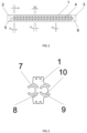
- FIG. 1 is a structural schematic view of a preferred embodiment of the endoscopic bending tube of the invention.
- the endoscopic bending tube comprises a bending tube, and a tubular steel wire rope welding section 2 and a tubular connect collar fixing section 3 respectively connected to both ends of the bending tube, wherein the bending tube includes 19 tubular unit segments connected in series.
- Two adjacent unit segments 1 are connected by an embedded structure 4, wherein the embedded structure 4 includes a first rotation part and a second rotation part respectively disposed at two ends of the unit segment, and the adj acent unit segments 1 are connected through the embedment of the first rotation part and the second rotation part to achieve the relative rotation of the adjacent unit segments 1.
- the upper and the lower parts of the two ends of the unit segment 1 are bevels.
- the angle formed with the upper parts and the angle formed with the lower parts of the adjacent unit segments 1 both have A degree.
- the front part of the endoscopic bending tube refers to the steel wire rope welding section and the unit segment connected thereto.
- the angle formed with the upper parts of the adj acent unit segments 1 has B degree, and the angle formed with the lower parts of the adjacent unit segments 1 has C degree.
- the angle formed with the upper parts of the adjacent unit segments has B degree, and the angle formed with the lower parts of the adjacent unit segments has D degree;
- the size sequence of the angles is C>B>A>D. That is to say, the side on which the angle of C degree is located is the large angle side, and the side on which the angle of B degree is located is the small angle side.
- two riveting positions 5 are arranged respectively at the opposite sides of the circumference of the steel wire rope welding section, and a processing hole 6 is arranged adjacent to one of the riveting positions 5.
- two processing holes 6 are arranged respectively at the opposite sides of the circumference of the connect collar fixing section. Both sides of the inner wall of the unit segments are provided with through holes at corresponding positions for insertions of steel wire ropes.
- the first rotating part includes a first ring 7 provided with an opening and an annular first groove 8 arranged at the outer side of the first ring 7.
- the second rotating part includes a second ring 9 provided with an opening and an annular second groove 10 arranged at the inner side of the second ring 9.
- the second ring 9 can be inserted into the first groove 8, and the second ring 9 can rotate in the first groove 8.
- the first ring 7 can be inserted into the second groove 10, and the first ring 7 can rotate in the second groove 10.
- the endoscopic bending tube is a stainless steel tube cut by laser, and the bending is realized by cutting perpendicular to the length of the bending tube towards the axis of the metal tube with laser to form the rings and the grooves.
- the end of the steel wire rope welding section 2 is equipped with the head base of the endoscope.
- the head base of the endoscope is generally equipped with working parts such as CMOS image sensor, light guide hole, working channel, water jet hole, etc.
- two steel ropes are arranged inside the endoscopic bending tube, and the two steel ropes pass through the through holes arranged on the inner wall of the unit segment 1 and are fixed on the riveting positions of the steel wire rope welding section 2.
- the through hole is a hollow pipe which is arranged along the length direction of the bending tube, and the axis of the through hole is in the same plane as the rotation direction of the bending tube.
- the endoscopic bending tube When the wire rope at the large angle side is pulled, the endoscopic bending tube will bend at the large angle side, as shown in FIG. 4 , which is the bending state at the large angle side of the endoscopic bending tube.
- FIG. 4 which is the schematic views of the use states of the embodiment, the endoscopic bending pipes in the bending states both have smooth arc shapes.
- the unit segments of the endoscopic bending tube are connected by rivet structures, the endoscopic bending tube with this structure cannot automatically spring back to the original state after being rotated.
- the endoscopic bending tube of the invention is integrally cut from a stainless steel tube, rather than being connected by individual unit segments after the stainless steel tube is cut into the individual unit segments.
- the endoscopic bending tube is an integral component, when the wire rope is pulled to bend the endoscopic bending tube, a certain resilience will be generated. When the wire rope is released, the endoscopic bending tube will automatically return to the original state.
- the invention improves the convenience and the feeling in use.
- the endoscopic bending tube of the invention is cut by a stainless steel tube, which has the advantages of convenient processing, low manufacturing cost, good bending shape, high bending flexibility and reliable quality.
Landscapes
- Health & Medical Sciences (AREA)
- Life Sciences & Earth Sciences (AREA)
- Surgery (AREA)
- Engineering & Computer Science (AREA)
- Biomedical Technology (AREA)
- Molecular Biology (AREA)
- Pathology (AREA)
- Radiology & Medical Imaging (AREA)
- Nuclear Medicine, Radiotherapy & Molecular Imaging (AREA)
- Biophysics (AREA)
- Physics & Mathematics (AREA)
- Heart & Thoracic Surgery (AREA)
- Medical Informatics (AREA)
- Optics & Photonics (AREA)
- Animal Behavior & Ethology (AREA)
- General Health & Medical Sciences (AREA)
- Public Health (AREA)
- Veterinary Medicine (AREA)
- Manufacturing & Machinery (AREA)
- Instruments For Viewing The Inside Of Hollow Bodies (AREA)
- Endoscopes (AREA)
Applications Claiming Priority (2)
| Application Number | Priority Date | Filing Date | Title |
|---|---|---|---|
| CN202120034208.0U CN214906586U (zh) | 2021-01-07 | 2021-01-07 | 内窥镜弯曲管 |
| PCT/CN2021/142304 WO2022148280A1 (zh) | 2021-01-07 | 2021-12-29 | 内窥镜弯曲管 |
Publications (2)
| Publication Number | Publication Date |
|---|---|
| EP4275584A1 true EP4275584A1 (de) | 2023-11-15 |
| EP4275584A4 EP4275584A4 (de) | 2024-11-13 |
Family
ID=79121202
Family Applications (1)
| Application Number | Title | Priority Date | Filing Date |
|---|---|---|---|
| EP21917319.2A Pending EP4275584A4 (de) | 2021-01-07 | 2021-12-29 | Biegerohr für endoskop |
Country Status (3)
| Country | Link |
|---|---|
| EP (1) | EP4275584A4 (de) |
| CN (1) | CN214906586U (de) |
| WO (1) | WO2022148280A1 (de) |
Families Citing this family (4)
| Publication number | Priority date | Publication date | Assignee | Title |
|---|---|---|---|---|
| CN214906586U (zh) * | 2021-01-07 | 2021-11-30 | 上海视介光电科技有限公司 | 内窥镜弯曲管 |
| US20240148238A1 (en) * | 2022-11-03 | 2024-05-09 | Boston Scientific Scimed, Inc. | Single piece articulating joint |
| CN115813318B (zh) * | 2022-12-30 | 2024-05-14 | 湖南省华芯医疗器械有限公司 | 一种内窥镜的连接元件、蛇骨、内窥镜及蛇骨组装方法 |
| US20240268642A1 (en) * | 2023-02-14 | 2024-08-15 | Boston Scientific Scimed, Inc. | Single piece articulating links with on-axis bevel hinge cut |
Family Cites Families (14)
| Publication number | Priority date | Publication date | Assignee | Title |
|---|---|---|---|---|
| TWM414932U (en) * | 2011-01-21 | 2011-11-01 | xiang-de Zeng | Slewing structure for handheld endoscope |
| EP2581031A1 (de) * | 2011-10-13 | 2013-04-17 | Johann Klaffenböck | Abwinkelungsvorrichtung |
| JP5901859B1 (ja) * | 2014-04-15 | 2016-04-13 | オリンパス株式会社 | 内視鏡用湾曲管、内視鏡および内視鏡用湾曲管の製造方法 |
| WO2016043032A1 (ja) * | 2014-09-17 | 2016-03-24 | オリンパス株式会社 | 湾曲管及び湾曲管を備える内視鏡装置 |
| US10434288B2 (en) * | 2016-01-15 | 2019-10-08 | Cook Medical Technologies Llc | Locking medical guide wire |
| CN208228927U (zh) * | 2017-07-11 | 2018-12-14 | 上海成运医疗器械股份有限公司 | 内窥镜用无铆钉蛇骨组件 |
| CN208404499U (zh) * | 2017-07-28 | 2019-01-22 | 上海视介光电科技有限公司 | 内窥镜弯曲管及内窥镜 |
| CN108078535A (zh) * | 2018-01-04 | 2018-05-29 | 郑州润德光电科技有限公司 | 双环抱旋转结构、双环抱管体旋转结构、一体式管体旋转结构、医疗内窥镜用蛇骨和内窥镜 |
| CN108125665B (zh) * | 2018-01-09 | 2024-02-27 | 浙江成运医疗器械有限公司 | 弯曲半径可变的内窥镜用无铆钉蛇骨组件 |
| CN209018664U (zh) * | 2018-05-17 | 2019-06-25 | 上海安清医疗器械有限公司 | 内窥镜 |
| CN209360629U (zh) * | 2018-05-17 | 2019-09-10 | 上海安清医疗器械有限公司 | 可控弯曲管结构 |
| CN108553069B (zh) * | 2018-05-17 | 2020-08-28 | 黄琴 | 可控弯曲管结构 |
| CN209750985U (zh) * | 2018-12-25 | 2019-12-10 | 深圳市先赞科技有限公司 | 内窥镜 |
| CN214906586U (zh) * | 2021-01-07 | 2021-11-30 | 上海视介光电科技有限公司 | 内窥镜弯曲管 |
-
2021
- 2021-01-07 CN CN202120034208.0U patent/CN214906586U/zh active Active
- 2021-12-29 WO PCT/CN2021/142304 patent/WO2022148280A1/zh not_active Ceased
- 2021-12-29 EP EP21917319.2A patent/EP4275584A4/de active Pending
Also Published As
| Publication number | Publication date |
|---|---|
| WO2022148280A1 (zh) | 2022-07-14 |
| EP4275584A4 (de) | 2024-11-13 |
| CN214906586U (zh) | 2021-11-30 |
Similar Documents
| Publication | Publication Date | Title |
|---|---|---|
| EP4275584A1 (de) | Biegerohr für endoskop | |
| EP3195784A1 (de) | Biegerohr und endoskopvorrichtung mit dem biegerohr | |
| US9192288B2 (en) | Endoscope | |
| CN105852781B (zh) | 内窥镜的弯曲部以及内窥镜 | |
| EP3195788A1 (de) | Gekrümmter abschnitt eines endoskops | |
| JPH03264039A (ja) | 可撓管用アングル | |
| CN103068296A (zh) | 线引导构件 | |
| US11745361B2 (en) | Manipulator and joint structure thereof | |
| EP3087898A1 (de) | Endoskop | |
| JP5412056B2 (ja) | 内視鏡 | |
| WO2024131872A1 (zh) | 骨节单元、蛇骨管、插入管以及内窥镜 | |
| JP5226197B2 (ja) | 内視鏡用ガイドチューブ及び内視鏡装置 | |
| EP2692279A1 (de) | Endoskopvorrichtung | |
| JP2018143583A (ja) | 内視鏡 | |
| JP5555019B2 (ja) | ガイドチューブ | |
| JP6023636B2 (ja) | 胆道内視鏡システム | |
| JPH1119031A (ja) | 内視鏡の湾曲装置 | |
| JP2843370B2 (ja) | 内視鏡の湾曲装置 | |
| JP5030658B2 (ja) | 内視鏡 | |
| JP2017192596A (ja) | 内視鏡用スネア | |
| JP6502744B2 (ja) | 内視鏡装置 | |
| CN119679349A (zh) | 一种蛇骨组件、插入部以及内窥镜 | |
| JP2007252560A (ja) | 内視鏡の挿入部 | |
| JP4447123B2 (ja) | 内視鏡の挿入部の連結部 | |
| JP6600485B2 (ja) | 内視鏡装置 |
Legal Events
| Date | Code | Title | Description |
|---|---|---|---|
| STAA | Information on the status of an ep patent application or granted ep patent |
Free format text: STATUS: THE INTERNATIONAL PUBLICATION HAS BEEN MADE |
|
| PUAI | Public reference made under article 153(3) epc to a published international application that has entered the european phase |
Free format text: ORIGINAL CODE: 0009012 |
|
| STAA | Information on the status of an ep patent application or granted ep patent |
Free format text: STATUS: REQUEST FOR EXAMINATION WAS MADE |
|
| 17P | Request for examination filed |
Effective date: 20230731 |
|
| AK | Designated contracting states |
Kind code of ref document: A1 Designated state(s): AL AT BE BG CH CY CZ DE DK EE ES FI FR GB GR HR HU IE IS IT LI LT LU LV MC MK MT NL NO PL PT RO RS SE SI SK SM TR |
|
| DAV | Request for validation of the european patent (deleted) | ||
| DAX | Request for extension of the european patent (deleted) | ||
| A4 | Supplementary search report drawn up and despatched |
Effective date: 20241015 |
|
| RIC1 | Information provided on ipc code assigned before grant |
Ipc: G02B 23/24 20060101ALI20241009BHEP Ipc: A61B 1/00 20060101ALI20241009BHEP Ipc: A61B 1/005 20060101AFI20241009BHEP |