EP4275505B1 - Hanging line with smoking rod length measurement - Google Patents
Hanging line with smoking rod length measurement Download PDFInfo
- Publication number
- EP4275505B1 EP4275505B1 EP22172758.9A EP22172758A EP4275505B1 EP 4275505 B1 EP4275505 B1 EP 4275505B1 EP 22172758 A EP22172758 A EP 22172758A EP 4275505 B1 EP4275505 B1 EP 4275505B1
- Authority
- EP
- European Patent Office
- Prior art keywords
- rod
- elements
- length
- hanging line
- sausage
- Prior art date
- Legal status (The legal status is an assumption and is not a legal conclusion. Google has not performed a legal analysis and makes no representation as to the accuracy of the status listed.)
- Active
Links
Images
Classifications
-
- A—HUMAN NECESSITIES
- A22—BUTCHERING; MEAT TREATMENT; PROCESSING POULTRY OR FISH
- A22C—PROCESSING MEAT, POULTRY, OR FISH
- A22C15/00—Apparatus for hanging-up meat or sausages
- A22C15/001—Specially adapted for hanging or conveying several sausages or strips of meat
-
- A—HUMAN NECESSITIES
- A22—BUTCHERING; MEAT TREATMENT; PROCESSING POULTRY OR FISH
- A22C—PROCESSING MEAT, POULTRY, OR FISH
- A22C15/00—Apparatus for hanging-up meat or sausages
- A22C15/001—Specially adapted for hanging or conveying several sausages or strips of meat
- A22C15/002—Loops, hooks, cords for suspending single sausages; apparatus for making or conveying loops for sausages
-
- A—HUMAN NECESSITIES
- A22—BUTCHERING; MEAT TREATMENT; PROCESSING POULTRY OR FISH
- A22C—PROCESSING MEAT, POULTRY, OR FISH
- A22C15/00—Apparatus for hanging-up meat or sausages
- A22C15/007—Racks for storing or smoking suspended meat or sausages
Definitions
- the present invention relates to a system for producing sausage-shaped products each of which contain a flowable filling material in a tubular or bag-shaped packaging casing and a suspension element.
- the inventive system includes a clipping machine and a hanging line capable of measuring the length of the smoking rods.
- a filling material is fed by a filling machine through a filling tube of the clipping machine into a tubular casing material.
- the clipping machine closes the back end of the sausage-shaped product via a closing means, like closure clips, which are attached by respective closing tools.
- a suspension element like a suspension loop, may also be attached to said back end of said sausage-shaped product, enabling the sausage-shaped product to be hung up e.g. on a smoking rod or the like.
- the sausage-shaped product just produced is separated from the remaining casing material by a knife or the like of a cutting device of the clipping machine and is transferred out of the clipping machine to a hanging line.
- the smoking rod For loading (storing) the sausage-shaped product on a smoking rod, the smoking rod usually is provided in a loading position within the hanging line. Then, when the produced sausage-shaped product is removed from the clipping machine, the suspension loop is engaged by a transfer device and is threaded onto the smoking rod. When the smoking rod is filled with a desired number of sausage-shaped products, the filled smoking rod is moved out of the loading position and an empty smoking rod is placed to be filled next. Then the filled smoking is transferred out of the hanging line by an outfeed device to be supplied to the next treatment step or to a storage device such as a storage frame or a smoking carriage or the like.
- a storage device such as a storage frame or a smoking carriage or the like.
- EP 2 384 638 B1 describes a system for producing sausage-shaped products, which comprises a robot device for inserting and removing, i.e. handling or transferring, of filled smoking rods from a hanging line to a storage frame.
- a robot device for inserting and removing, i.e. handling or transferring, of filled smoking rods from a hanging line to a storage frame.
- Said machines may vary in size, in rate of production or in size of products.
- they also may vary in the kind of used rod-like elements, on which the sausage-like products are to be loaded and in the kind of storage frames, to which the rod-like elements are to be transferred.
- the aforesaid object is achieved by a method for handling longitudinal rod-like elements as defined in independent claim 1, and by a system for producing sausage-shaped products as defined in independent claim 10.
- the aforesaid object with respect to the system for controlling a robotic device is achieved by the features of claim 10.
- Advantageous configurations and further developments of the invention with regard to the method are described in dependent claims 2 to 9, and with regard to the system in dependent claims 11 to 15.
- a method for handling longitudinal rod-like elements, in particular smoking rods, for storing sausage-shaped products, in particular sausages, in a system for producing and handling the sausage-shaped products, wherein the method comprises the steps of: providing a plurality of the rod-like elements, each rod-like element having a length defined between a first end and a second end; providing a clipping machine configured to produce the sausage-shaped products; providing a hanging line configured to load the produced sausage-shaped products on the rod-like elements and comprising a measuring position for receiving the rod-like elements and for measuring the length of the rod-like elements, and a loading position for receiving the rod-like elements and for loading the produced sausage-shaped products on the rod-like elements, wherein the measuring position is defined by a first support element configured to receive the first end of one of the rod-like elements and a second support element configured to receive the second end of the one of the rod-like elements, and wherein the loading position is defined by a third support element configured to receive the first end of the one of
- a control unit controlling the clipping machine and the hanging line may indicate to a user that a rod-like element is discarded, so that the user may remove the unsuitable rod-like element.
- the hanging line further comprises a magazine for holding available the plurality of the rod-like elements, wherein the measuring position of the hanging line is located within the magazine, and wherein the step of discarding comprises removing the one of the rod-like elements from the measuring position directly into a reject bin.
- the discarded rod-like elements do not need to travel to the loading position and the whole way through and out of the hanging line, which saves time and helps avoiding any interruption of the production operation.
- the measuring position and the loading position are one and the same, so that the step of measuring is performed with the one of the rod-like elements placed in the loading position. This is in particular advantageous, since the step of measuring is performed immediately before the step of loading, so that an additional transfer operation from a measuring position to a loading position can be omitted.
- the hanging line further comprises an outfeed device, wherein the method further comprises the step of moving the one of the rod-like elements by the outfeed device from the loading position to an output position.
- This outfeed device advantageously provides the above mentioned normal way of outputting the rod-like element. In this way, a filled rod-like element can be easily taken away from a robot, for example, in order to transfer it to the next treatment step or to a storage device.
- the step of discarding comprises removing the one of the rod-like elements from the output position, either manually by a user or automatically by a robot.
- the step of discarding further comprises stopping the operation of the clipping machine until a next one of the rod-like elements has been placed in the loading position of the hanging line and its length has been determined to be within the tolerance range.
- the step of discarding further comprises deferring the step of feeding the next one of the rod-like elements to the loading position of the hanging line until a user manually removes the discarded rod-like element and confirms the removal to the system.
- the system indicates to the user that a discarded rod-like element must be removed and separates out from the production process, wherein the user acknowledges removal to the system so that the system can resume operation.
- the system further comprises a handling robot configured to grip and move the one of the rod-like elements, wherein the handling robot grips the rod-like element, which is loaded with the predetermined number of the produced sausage-shaped products, and places the rod-like element in a storage frame, if the length is within the tolerance range; wherein the step of discarding further comprises removing the discarded rod-like element from the output position and placing the same in a reject bin by the handling robot.
- the storage frame comprises two support bars having a distance smaller than the desired length, and wherein if the length is within the tolerance range, the handling robot places the one of the rod-like elements on the support bars and perpendicular to the same such that both ends overlap the support bars by the same amount. Since a tolerance range around the desired length is admissible, it is advantageous to take into account the varying length of the rod-like elements when placing them on the support bars of the storage frame, so that the risk of sliding off from the support bars is minimized, even if the storage frame is subject to vibrations or shocks.
- a system for producing sausage-shaped products, like sausages, containing a flowable filling material in a tubular or bag-shaped packaging casing and a suspension element such as a suspension loop, and for loading the produced sausage-shaped products on rod-like elements, such as smoking rods, each rod-like element having a length defined between a first end and a second end.
- the system comprises: a clipping machine configured to produce the sausage-shaped products; a hanging line configured to load the produced sausage-shaped products on the rod-like elements; and a control unit controlling the operation of the clipping machine and the hanging line.
- the hanging line comprises: a first support element configured to receive the first end of one of the rod-like elements and a second support element configured to receive the second end of the one of the rod-like elements, the first and second support elements defining a measuring position; and a third support element configured to receive the first end of the one of the rod-like elements and a fourth support element configured to receive the second end of the one of the rod-like elements, the third and fourth support elements defining a loading position for loading the produced sausage-shaped products on the rod-like elements; a sensor device arranged at the measuring position and configured to measure the length of the one of the rod-like elements placed in the measuring position; wherein the control unit is configured to compare the length with a desired length and to determine whether the length is within a tolerance range of the desired length, and wherein the control unit further causes the hanging line to load a predetermined number of sausage-shaped products on the one of the rod-like elements if the length is within the tolerance range, and causes discarding the one of the rod-like elements if the length is not within
- the hanging line further comprises a magazine for holding available a plurality of the rod-like elements, wherein the first and second support elements defining the measuring position are located within the magazine, and wherein the magazine is configured to successively feed single rod-like elements first to the measuring position and then to the loading position or to a reject bin.
- the magazine may have two output paths which can be switched automatically, so that the removal of unsuitable rod-like elements into a reject bin may be performed automatically, and no intervention of a user is required.
- the reject bin may be located beneath one of these output paths, so that the discarded rod-like can fall into the reject bin.
- the first and third support elements are one and the same and the second and fourth support elements are one and the same, so that the measuring position is identical with the loading position and the sensor device is arranged at the loading position; and wherein the hanging line further comprises an outfeed device configured to move the one of the rod-like elements from the loading position to an output position.
- an outfeed device configured to move the one of the rod-like elements from the loading position to an output position.
- the system further comprises a storage frame having two support bars with a distance smaller than the desired length for carrying a plurality of the rod-like elements; and a handling robot configured to grip the one of the rod-like elements and to place it on the support bars of the storage frame or in a reject bin); wherein the handling robot is further configured to receive the measured length of the one of the rod-like elements from the control unit and to adjust the placing position of the one of the rod-like elements on the support bars such that both ends overlap the support bars by the same amount.
- the sensor device comprises a pushing device arranged at the third support element and having a ram configured to push against the first end in a longitudinal direction of the one of the rod-like elements, so that the second end becomes aligned with the fourth support element acting as a stop; wherein the pushing device comprises a sensor configured to detect a position of the ram and to generate an output signal depending on the position of the ram; and wherein the control unit is configured to receive the output signal of the sensor and to determine the length of the one of the rod-like elements based on the signal when the second end is aligned with the fourth support element.
- the pushing device comprises a pneumatic cylinder fixedly attached with respect to the third support element and a piston having a magnetic element and coupled to the ram, and wherein the sensor is a magnetic sensor, in particular a Hall-Sensor, attached to the pneumatic cylinder and configured to detect an axial position of the piston.
- the sensor is a magnetic sensor, in particular a Hall-Sensor, attached to the pneumatic cylinder and configured to detect an axial position of the piston.
- the inventive method thereby provides all advantages explained in conjunction with the inventive system for producing sausage-shaped products.
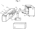
- An embodiment of a system for producing and handling sausage-like products according to Fig. 1 comprises as main components a schematically shown production line 3 for producing sausage-like products S, like sausages, and storing them on rod-like elements R, like smoking rods, including a control unit 160 for controlling the production line 3, a handling robot 300 having a control unit 310 for controlling the movement of robot 300, and a storage frame 400, into which the sausages S hung up at the smoking rods R are to be moved.
- the robot 300 is not obligatory for the invention, and that the rod-like elements can also be manually moved by a user.
- a reject bin 900 may be provided into which a user or robot 300 may place rod-like elements which are discarded, as described later.
- Production line 3 comprises a clipping machine 100 for producing the sausage-like products S and an automatic hanging line 200 for loading (storing) the produced sausage-like products S on the smoking rods (rod-like elements) R.
- Hanging line 200 preferably includes or is combined with an outfeed device 220 having horizontal rails 222 for supporting the rod-like elements R which carry sausage-like products S and leave hanging line 200.
- Control unit 160 of production line 3 and control unit 310 of robot 300 may communicate with each other via common techniques like wireless connections or wired connections, in order to coordinate the operations.
- storage frame 400 When operating the system, storage frame 400 is positioned in an operating range of handling robot 300. Inside storage frame 400, tray rails or shelf rails e.g. in the form of horizontally aligned support bars 402, 404 are arranged for positioning smoking rods R thereon.
- Handling robot 300 preferably is a so called joined-arm robot. Construction and operation of such robot 300 in such system is described in detail in EP 2 384 638 B1 .
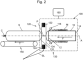
- a clipping machine 100 for producing sausage-shaped products S is schematically shown in Fig. 2 , and comprises as main components a filling tube 10 having a longitudinally extending center axis A and with a discharge opening for a filling material at its left end 12 and a feeding opening for the filling material fed to the filling tube 10 by a feeding pump at its right end 14, a casing brake assembly 16 arranged coaxially with filling tube 10 in the region of the left end 12 of filling tube 10.
- Filling tube 10 is made of a suitable material, like stainless steel.
- a supply of tubular packaging casing material M made of a thin sheet material is stored on the filling tube 10.
- Clipping machine 100 further comprises a clipping device 120 for closing a filled tubular packaging casing M by applying closure means, like closure clips C, to a plait-like portion P, and gathering means 130 for gathering the filled tubular packaging casing M and for forming said plait-like portion P thereto, and which are all arranged downstream filling tube 10.
- Right end 14 of horizontally arranged filling tube 10 is coupled to a filler arrangement (not shown) including a pump for feeding filling material through filling tube 10 in a feeding direction F into tabular packaging casing M closed on its front end facing in the feeding direction F, by a closure clip C.
- a filler arrangement (not shown) including a pump for feeding filling material through filling tube 10 in a feeding direction F into tabular packaging casing M closed on its front end facing in the feeding direction F, by a closure clip C.
- clipping device 120 is arranged and coaxially aligned to filling tube 10.
- Clipping device 120 comprises a first and a second clipping tool 122, 124 formed by a punch 122 and a die 124. It has to be noted that punch 122 and die 124 may apply and close a single closure clip C for closing the just filled tubular packaging casing M, or may apply and close two closure clips C at the same time, a first closure clip C for closing the just filled tubular packaging casing M for forming a sausage-shaped product S, and a second closure clip C for closing the front end of the tubular packaging casing M subsequently to be filled.
- Gathering means 130 includes a first displacer unit 132 and a second displacer unit 134, wherein first displacer unit 132 is positioned downstream second displacer unit 134.
- First and second clipping tools 122, 124 of clipping device 120 may be positioned between first and second displacer units 132, 134, at least for applying and closing one or two closure clips C to plait-like portion P.
- a suspension element like a suspension loop SL
- suspension loop L is provided in the movement path of die 124 such that suspension loop L is engaged by a closure clip C halt in die 124 to be applied to plait-like portion P and attached thereto together with closure clip C.
- Clipping machine 100 further comprises a conveying device 150 for conveying sausage-shaped product S towards hanging line 200.
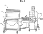
- Fig. 3 shows a schematic perspective overview of a production line 3 according to the invention.
- clipping machine 100 is combined with hanging line 200.
- Hanging line 200 receives the sausage-shaped products S from clipping machine 100 and rod-like elements R from a magazine 210, for example, which is attached to a frame 250 of hanging line 200.
- Hanging line 200 preferably comprises an outfeed device 220 which comprises two horizontally arranged rails 222 for supporting the rod-like elements R leaving a loading position of hanging line 200 to an output position 224 located at the outermost ends of rails 222 (i.e. the front ends in Fig. 3 ).
- the loading position (not depicted since the loading device 260 is not shown) resides on the opposite, i.e. inner ends of rails 222.
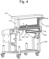
- each rail 222 of outfeed device 220 comprises a circulating chain 223 configured to engage and move one of the ends E1, E2 of rod-like element R towards the output position.
- magazine 210 may comprise an upstream wall 212 and a downstream wall 214 (with respect to the transfer direction T), which are arranged parallel to each other and approximately vertically above rails 222. The distance between walls 212, 214 corresponds to the desired length of a rod-like element R plus a margin. In the surfaces of walls 212, 214 facing each other, vertical slots 216 are arranged parallel to each other. Slots 216 extend from the upper end of walls 212, 214 and commonly end in a funnel-shaped recess (not shown).
- Magazine 210 further comprises releasing means (not shown) for blocking the rod-like elements R positioned in slots 216, and for selectively releasing a single rod-like element R from one of slots 216 at the lower ends of slots 216.
- releasing means for blocking the rod-like elements R positioned in slots 216, and for selectively releasing a single rod-like element R from one of slots 216 at the lower ends of slots 216.
- a single slot 218 is arranged into which single rod-like element R is moved after being selectively released from slots 216.
- Slots 218 provide a standby position in which a single, empty rod-like element R is kept ready for being fed into the loading position after a filled rod-like element R has been removed out of the loading position.
- second blocking and releasing elements 434 in the form of release pins are arranged for securing a single rod-like element R in the standby position, and for releasing rod-like element R for further feeding towards the loading position.
- magazine 210 and outfeed device 220 are known and described in EP 3 241 447 A1 in detail, so that a more detailed description is omitted here.
- magazine 210 comprises a first support element 202 configured to receive the first end E1 of a rod-like element R and a second support element 204 configured to receive the second end E2 of the rod-like element R.
- the first and second support elements 202, 204 define a measuring position.
- Support elements 202, 204 are each arranged directly below slots 218, so that a rod-like element leaving slots 218 is fed onto support elements 202, 204 into a measuring position.
- Fig. 4 only the location of support element 202 of wall 212 is indicated, while support element 204 is located in the opposite wall 214.
- Support elements 202, 204 may be configured as explained in connection with Fig. 7 below.
- a sensor device as shown in Fig.
- the output slots each may include a slot switch (not shown) and divide in first and second output paths for outputting the rod-like element R.
- slot switches per-se are well-known.
- the first output path leads to support elements 202, 204 of the loading position of hanging line 200, while the second output path leads out of magazine 210 and hanging line 200 so that the rod-like element R can be discarded and received in a reject bin 900 located beneath magazine 210, for example.
- a method of operating the first embodiment is described.
- one of the rod-like elements R is fed by magazine 210 from slots 218 to the measuring position formed by support elements 202, 204.
- the length L of that rod-like element R is measured by sensor device 240.
- sensor device 240 generates an electric signal which is used by control unit 160 to determine the length L.
- control unit 160 determines whether the length L is within a predetermined tolerance range of a desired length Ld.
- the processing advances to a fifth step, in which the rod-like element R is transferred via the first output path of magazine 210 to the loading position defined by third and fourth support elements 206, 208 of hanging line 200 and a predetermined number of the produced sausage-shaped products S is loaded on the rod-like element R (as described later herein and shown in Figs. 6 and 7 ), whereupon the filled rod-like element R is removed from the loading position and transferred to the output position by outfeed device 220.
- the processing then returns to the first step.
- the processing advances to a sixth step, in which the rod-like element R is discarded and transferred via the second output path out of hanging line 200 and, for example, into the reject bin 900.
- the processing then returns to the first step.
- magazine 210 does not include the measuring position with first and second support elements 202, 204, the sensor device 240 and the slot switches and first and second output paths as described above. Instead, magazine 210 includes only one output path leading to the loading position of hanging line 200.
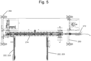
- Fig. 5 is a top view showing the main components of hanging line 200
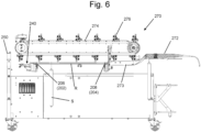
- Fig. 6 is a side view of the hanging line 200 of Fig. 5.
- Figs. 5 and 6 particularly show the loading device 270 which is supported by frame 250 of hanging line 200 and located at the inner ends of rails 222 of the outfeed device 220 and above a rod-like element R placed in the loading position.
- Loading device 270 per se is well-known and can have different configurations.
- Loading device 270 as shown, comprises a transfer device 272 and a circulating loading chain 274 carrying engagement elements 276.
- loading device 270 comprises third and fourth support elements 206, 208 defining a loading position and being configured to support first and second ends E1, E2 of rod-like element R.
- third and fourth support elements 206, 208 also serve as, i.e. are identical to or one and the same with, first and second support elements 202, 204.
- the loading position defined by third and fourth support elements 206, 208 is also used as the measuring position for measuring the length L of the rod-like element R.
- sensor device 240 is attached to third support element 206.
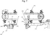
- Transfer device 272 is configured to catch suspension loop SL of the sausage-like product S leaving clipping machine 100, and to deliver suspension loop SL via a slip 273 to rod-like element R resting with its second end E2 on fourth support element 208. While sliding on slip 271, suspension loop SL is engaged by engagement elements 276 circulating with chain 274, and thus, moved over the left end of slip 273 onto rod-like element R. Fourth support element 208 is attached to the left end of slip 273, as is best shown in Fig. 7 , and retains second end E2 of rod-like element R in lateral directions aligned with slip 273.
- second end E2 of rod-like element R should abut to the end surface of slip 273, which end surface is a stop 209 of fourth support element 208, so as to avoid any gap between rod-like element R and slip 273 for ensuring smooth transition of suspension loop SL.
- This alignment of rod-like element R with stop 209 of support element 208 advantageously can be performed by a pushing element 242 of sensor element 240 described below.
- Sensor element 240 comprises a frame 241 to be fixedly attached with respect to third support element 206, and a pushing device 242 carried by frame 241.
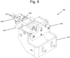
- Pushing device 242 comprises a ram 244 guided in the axial direction of axis A of rod-like element R by a linear feed 245 having posts guided in longitudinal holes of frame 241 (see Fig. 8 ).
- ram 244 is shown without a contact element, while in Fig. 9 , a contact element, preferable made of plastic or hard rubber or the like, is attached to the front face of ram 244 which is intended to engage first end E1 of rod-like element R.
- ram 244 is coupled via a piston rod with a piston (not shown) of a pneumatic cylinder 248, so that ram 244 can be moved in the direction of axis A of rod-like element R.
- Pneumatic cylinder 248 is attached to frame 241.
- a clamping device 247 is attached to pneumatic cylinder 248 such that it encloses and clamps a sensor 246 to a location in the vicinity of pneumatic cylinder 248 which is mad of non-magnetic material, so that sensor 246 can detect a magnetic field generated by a magnetic element included in the piston or the piston rod of pushing device 242.
- sensor 246 is a Hall-Sensor or a magneto-resistive sensor or the like, and depending on the position of the magnetic element contained in the piston or in the piston rod of pushing element 242, sensor 246 generates a varying electrical signal.
- Control unit 160 can then receive this electrical signal from sensor 246 a cable 243 and determine the position of the piston based on the electrical signal.
- the position of ram 244 can be determined, and since the fixed distance between third and fourth support elements 206, 208 is known, control unit 160 can calculate the actual distance between the end face of the contact element of ram 244 and the surface of stop 209 of fourth support element 208.
- This distance corresponds to the length L of rod-like element R placed in the loading (or measuring) position when ram 244 pushes against first end E1 of rod-like element R and second end E2 of the same abuts on (i.e. is aligned with) stop 209.
- length L of rod-like element R can be determined.
- sensor element 240 is capable of performing two functions simultaneously, namely aligning second end E2 of rod-like element R with stop 209 and slip 273, respectively, as well as measuring the length L of rod-like element R.
- the invention is not restricted to a magnetic sensor. Instead, also other position sensors can be used, such as optical sensors. Moreover, the invention is not restricted to pushing device 242 having pneumatic cylinder 248, but can also be implemented with a ram 244 driven electrically such as by a solenoid or the like. Sensor device 240 described above can be used in the above described first embodiment, when attached to first support element 202. In this case, second support element 204 also has a stop similar to stop 209 of fourth support element 208.
- a method of operating the second embodiment is described.
- one of the rod-like elements R is fed by magazine 210 to the measuring position, which in this case corresponds to the loading position defined by third and fourth support elements 206, 208.
- the length L of that rod-like element R is measured by sensor device 240, while aligning rod-like element to stop 209 of fourth support element 208 at slip 273.
- sensor device 240 generates an electric signal which is used by control unit 160 to determine the length L.
- control unit 160 determines whether the length L is within a predetermined tolerance range of a desired length Ld.
- the processing advances to a fifth step, in which a predetermined number of the produced sausage-shaped products S is loaded on the rod-like element R by loading device 270, whereupon the filled rod-like element R is removed from the loading position and transferred to the output position by outfeed device 220.
- the processing then returns to the first step.
- the processing advances to a sixth step, in which the rod-like element R is discarded and transferred to the output position by outfeed device 220, whereupon the discarded rod-like element R must be removed either by a user or by robot 300.
- the processing then returns to the first step.
- the system can stop the clipping machine and/or the hanging line until the user confirms removal of the discarded rod-like element R. This avoids that sausage-like products S are produced which cannot be moved further along the production process.
- the system comprises the handling robot 300
- the discarded rod-like element R can be removed from the output position of outfeed device 220 by robot 300, and can be placed in the reject bin 900, for example. Thus, the production process can be smoothly continued.
- control unit 160 of production line 3 determines the length of rod-like element R, this length can be used by handling robot 300 to optimize the placing position of rod-like element R on storage frame 400.
- control device 160 can transmit the value of length L of rod-like element R currently presented in the output position of outfeed device 220 to control unit 310 of handling robot 300.
- the longitudinal position of rod-like element R in the output position is well defined due to the alignment of rod-like element R in the loading position, if it is assumed that during the outfeed operation of outfeed device the axial position is not considerably changed. It is also possible, to provide a further alignment device (not shown) at the output position to ensure a well defined axial position of rod-like element R.
- handling robot 300 is able to grip rod-like element R at the output position in a well known distance from both ends E1, E2 of rod-like element R, so that the handling robot 300 is further able to place rod-like element R perpendicular to and on support bars 402, 404 of storage frame 400 such that both ends E1, E2 overlap support bars 402, 404 by the same amount.
- handling robot 300 can place rod-like element R centred on support bars 402, 404. This improves stability of the position of rod-like element R in storage frame 400 and reduces the risk of slipping off from the support bars 402, 404 when storage frame 400 is subject to vibrations or shock.
- Sensor device 240 attached to one of the support elements of the loading position can also be added to hanging lines 200 already in operation, so that all the advantages described above can be added to older systems when control unit 160 of production line 3 and, if applicable, control unit 310 of handling robot 300 are reprogrammed accordingly so as to perform the methods of the invention.
Landscapes
- Life Sciences & Earth Sciences (AREA)
- Engineering & Computer Science (AREA)
- Wood Science & Technology (AREA)
- Zoology (AREA)
- Food Science & Technology (AREA)
- Specific Conveyance Elements (AREA)
Description
- The present invention relates to a system for producing sausage-shaped products each of which contain a flowable filling material in a tubular or bag-shaped packaging casing and a suspension element. In particular, the inventive system includes a clipping machine and a hanging line capable of measuring the length of the smoking rods.
- In the production of sausage-shaped products, like sausages, a filling material is fed by a filling machine through a filling tube of the clipping machine into a tubular casing material. After a predetermined volume of filling material has been filled into said tubular casing material, the clipping machine closes the back end of the sausage-shaped product via a closing means, like closure clips, which are attached by respective closing tools. A suspension element, like a suspension loop, may also be attached to said back end of said sausage-shaped product, enabling the sausage-shaped product to be hung up e.g. on a smoking rod or the like. Afterwards, the sausage-shaped product just produced, is separated from the remaining casing material by a knife or the like of a cutting device of the clipping machine and is transferred out of the clipping machine to a hanging line.
- For loading (storing) the sausage-shaped product on a smoking rod, the smoking rod usually is provided in a loading position within the hanging line. Then, when the produced sausage-shaped product is removed from the clipping machine, the suspension loop is engaged by a transfer device and is threaded onto the smoking rod. When the smoking rod is filled with a desired number of sausage-shaped products, the filled smoking rod is moved out of the loading position and an empty smoking rod is placed to be filled next. Then the filled smoking is transferred out of the hanging line by an outfeed device to be supplied to the next treatment step or to a storage device such as a storage frame or a smoking carriage or the like.
-
EP 2 384 638 B1 describes a system for producing sausage-shaped products, which comprises a robot device for inserting and removing, i.e. handling or transferring, of filled smoking rods from a hanging line to a storage frame. In the field of production of sausage-like products, there is a great variety of machines being components of the respective production line. Said machines may vary in size, in rate of production or in size of products. Thus, they also may vary in the kind of used rod-like elements, on which the sausage-like products are to be loaded and in the kind of storage frames, to which the rod-like elements are to be transferred. Usually, in a production site for producing sausage-like products, different kinds of machines for different products having different sizes are used, so that also different kinds of rod-like elements are simultaneously used at a production site. Accordingly, it cannot be ruled out that erroneously an unsuitable rod-like element is supplied to a hanging line of a clipping machine. In particular when the rod-like element has a axial length deviating from a desired length too much, problems may occur during handling of the rod-like element or during a subsequent treatment process. For example, both end portions of the rod-like elements may be placed on two support bars of a storage frame such that the ends overlap the support bars. When the rod-like element is too short, it may overlap supporting bars of a storage frame only by a small amount. When rolling the storage frame over the floor, vibrations of the storage frame may cause the rod-like element to move in axial direction, so that the risk of sliding off from the support bars increases in case of too short rod-like elements. As another problem, rod-like elements having an unsuitable length (i.e. too short or too long) may be stuck in the hanging line when filled with sausage-shaped products. As a result, interruptions of the processing and damaging of produced sausage-shaped products may occur. - Therefore, it is an object of the invention to provide a method and a system for handling rod-like elements in a system for producing sausage-shaped products, which ensure an improved reliability of operation and avoid the above problems.
- The aforesaid object is achieved by a method for handling longitudinal rod-like elements as defined in
independent claim 1, and by a system for producing sausage-shaped products as defined inindependent claim 10. The aforesaid object with respect to the system for controlling a robotic device is achieved by the features ofclaim 10. Advantageous configurations and further developments of the invention with regard to the method are described in dependent claims 2 to 9, and with regard to the system in dependent claims 11 to 15. - In the present invention, a method is provided for handling longitudinal rod-like elements, in particular smoking rods, for storing sausage-shaped products, in particular sausages, in a system for producing and handling the sausage-shaped products, wherein the method comprises the steps of: providing a plurality of the rod-like elements, each rod-like element having a length defined between a first end and a second end; providing a clipping machine configured to produce the sausage-shaped products; providing a hanging line configured to load the produced sausage-shaped products on the rod-like elements and comprising a measuring position for receiving the rod-like elements and for measuring the length of the rod-like elements, and a loading position for receiving the rod-like elements and for loading the produced sausage-shaped products on the rod-like elements, wherein the measuring position is defined by a first support element configured to receive the first end of one of the rod-like elements and a second support element configured to receive the second end of the one of the rod-like elements, and wherein the loading position is defined by a third support element configured to receive the first end of the one of the rod-like elements and a fourth support element configured to receive the second end of the one of the rod-like elements; feeding one of the rod-like elements to the measuring position of the hanging line; measuring the length of said one of the rod-like elements by a sensor device; determining by a control unit whether the length is within a tolerance range of a desired length; providing said one of the rod-like elements in the loading position of the hanging line and loading a predetermined number of the produced sausage-shaped products on said one of the rod-like element, if the length is within the tolerance range; discarding said one of the rod-like elements from the hanging line, if the length is not within the tolerance range. In this manner, advantageously unsuitable rod-like elements can be separated our from the production process, before loaded with sausage-shaped products. In some embodiments, a control unit controlling the clipping machine and the hanging line may indicate to a user that a rod-like element is discarded, so that the user may remove the unsuitable rod-like element.
- In some preferred embodiments, optionally, the hanging line further comprises a magazine for holding available the plurality of the rod-like elements, wherein the measuring position of the hanging line is located within the magazine, and wherein the step of discarding comprises removing the one of the rod-like elements from the measuring position directly into a reject bin. Hence, removal of unsuitable rod-like elements into a reject bin may be performed automatically, and no intervention of a user is required. Advantageously, the discarded rod-like elements do not need to travel to the loading position and the whole way through and out of the hanging line, which saves time and helps avoiding any interruption of the production operation.
- In some preferred embodiments, optionally, in the hanging line the measuring position and the loading position are one and the same, so that the step of measuring is performed with the one of the rod-like elements placed in the loading position. This is in particular advantageous, since the step of measuring is performed immediately before the step of loading, so that an additional transfer operation from a measuring position to a loading position can be omitted.
- In the above embodiment, optionally, the hanging line further comprises an outfeed device, wherein the method further comprises the step of moving the one of the rod-like elements by the outfeed device from the loading position to an output position. This outfeed device advantageously provides the above mentioned normal way of outputting the rod-like element. In this way, a filled rod-like element can be easily taken away from a robot, for example, in order to transfer it to the next treatment step or to a storage device. Optionally, in this case, the step of discarding comprises removing the one of the rod-like elements from the output position, either manually by a user or automatically by a robot.
- In some preferred embodiments, optionally, the step of discarding further comprises stopping the operation of the clipping machine until a next one of the rod-like elements has been placed in the loading position of the hanging line and its length has been determined to be within the tolerance range. This is advantageous, since it ensures reliable operation of the system, even if a plurality of unsuitable rod-like elements has been filled into the magazine, for example, so that it takes some time until the next suitable rod-like element arrives in the loading position of the hanging line.
- In the above embodiment, optionally, the step of discarding further comprises deferring the step of feeding the next one of the rod-like elements to the loading position of the hanging line until a user manually removes the discarded rod-like element and confirms the removal to the system. In case the discarded rod-like elements are not automatically removed from an output position of the outfeed device, the system indicates to the user that a discarded rod-like element must be removed and separates out from the production process, wherein the user acknowledges removal to the system so that the system can resume operation.
- In some preferred embodiments, optionally, the system further comprises a handling robot configured to grip and move the one of the rod-like elements, wherein the handling robot grips the rod-like element, which is loaded with the predetermined number of the produced sausage-shaped products, and places the rod-like element in a storage frame, if the length is within the tolerance range; wherein the step of discarding further comprises removing the discarded rod-like element from the output position and placing the same in a reject bin by the handling robot. In this way, separating out the unsuitably rod-like elements is performed automatically and quickly, so that an advantageous continuous production process can be achieved, in particular if only single unsuitable rod-like elements are occasionally supplied to the hanging line.
- In the above embodiment, optionally, the storage frame comprises two support bars having a distance smaller than the desired length, and wherein if the length is within the tolerance range, the handling robot places the one of the rod-like elements on the support bars and perpendicular to the same such that both ends overlap the support bars by the same amount. Since a tolerance range around the desired length is admissible, it is advantageous to take into account the varying length of the rod-like elements when placing them on the support bars of the storage frame, so that the risk of sliding off from the support bars is minimized, even if the storage frame is subject to vibrations or shocks.
- In the present invention, a system is provided for producing sausage-shaped products, like sausages, containing a flowable filling material in a tubular or bag-shaped packaging casing and a suspension element such as a suspension loop, and for loading the produced sausage-shaped products on rod-like elements, such as smoking rods, each rod-like element having a length defined between a first end and a second end. The system comprises: a clipping machine configured to produce the sausage-shaped products; a hanging line configured to load the produced sausage-shaped products on the rod-like elements; and a control unit controlling the operation of the clipping machine and the hanging line. The hanging line comprises: a first support element configured to receive the first end of one of the rod-like elements and a second support element configured to receive the second end of the one of the rod-like elements, the first and second support elements defining a measuring position; and a third support element configured to receive the first end of the one of the rod-like elements and a fourth support element configured to receive the second end of the one of the rod-like elements, the third and fourth support elements defining a loading position for loading the produced sausage-shaped products on the rod-like elements; a sensor device arranged at the measuring position and configured to measure the length of the one of the rod-like elements placed in the measuring position; wherein the control unit is configured to compare the length with a desired length and to determine whether the length is within a tolerance range of the desired length, and wherein the control unit further causes the hanging line to load a predetermined number of sausage-shaped products on the one of the rod-like elements if the length is within the tolerance range, and causes discarding the one of the rod-like elements if the length is not within the tolerance range.
- In the above embodiment, optionally, the hanging line further comprises a magazine for holding available a plurality of the rod-like elements, wherein the first and second support elements defining the measuring position are located within the magazine, and wherein the magazine is configured to successively feed single rod-like elements first to the measuring position and then to the loading position or to a reject bin. To this, the magazine may have two output paths which can be switched automatically, so that the removal of unsuitable rod-like elements into a reject bin may be performed automatically, and no intervention of a user is required. The reject bin may be located beneath one of these output paths, so that the discarded rod-like can fall into the reject bin.
- In some preferred embodiments, optionally, the first and third support elements are one and the same and the second and fourth support elements are one and the same, so that the measuring position is identical with the loading position and the sensor device is arranged at the loading position; and wherein the hanging line further comprises an outfeed device configured to move the one of the rod-like elements from the loading position to an output position. This is particularly advantageous, since this saves space and components in the hanging line, and the unsuitable rod-like elements can be discarded by removing it along the normal way and the magazine can be constructed more simple. Alternatively, it is also possible to provide a reject mechanism configured to reject unsuitable rod-like elements from the loading position directly into the reject bin, for example in a direction away from the outfeed device.
- In some preferred embodiments, optionally, the system further comprises a storage frame having two support bars with a distance smaller than the desired length for carrying a plurality of the rod-like elements; and a handling robot configured to grip the one of the rod-like elements and to place it on the support bars of the storage frame or in a reject bin); wherein the handling robot is further configured to receive the measured length of the one of the rod-like elements from the control unit and to adjust the placing position of the one of the rod-like elements on the support bars such that both ends overlap the support bars by the same amount.
- In some preferred embodiments, optionally, the sensor device comprises a pushing device arranged at the third support element and having a ram configured to push against the first end in a longitudinal direction of the one of the rod-like elements, so that the second end becomes aligned with the fourth support element acting as a stop; wherein the pushing device comprises a sensor configured to detect a position of the ram and to generate an output signal depending on the position of the ram; and wherein the control unit is configured to receive the output signal of the sensor and to determine the length of the one of the rod-like elements based on the signal when the second end is aligned with the fourth support element. In this embodiment, optionally, the pushing device comprises a pneumatic cylinder fixedly attached with respect to the third support element and a piston having a magnetic element and coupled to the ram, and wherein the sensor is a magnetic sensor, in particular a Hall-Sensor, attached to the pneumatic cylinder and configured to detect an axial position of the piston. This arrangement provides a simple and reliable mechanism for measuring the length of the rod-like elements. Moreover, in case that the measuring position is identical to the loading position, a step of aligning the rod-like element for the loading operation can be advantageously performed simultaneously with the step of measuring.
- The inventive method thereby provides all advantages explained in conjunction with the inventive system for producing sausage-shaped products.
- Further advantages and preferred embodiments of the present invention will be described in the following together with the drawings listed below. The expressions "left", "right", "below" and "above" used in the following description, are referred to the drawings in an alignment such that the reference numbers and the notation of the figures used can be read in normal orientation.
- Fig. 1:
- is a schematic view showing the principal design of a system for producing sausage-shaped products;
- Fig. 2:
- is a schematic view showing the principal design of a clipping machine of the system of
Fig. 1 ; - Fig. 3:
- is a schematic perspective view showing a production line according to the invention;
- Fig. 4:
- is a schematic perspective rear view of a part of a hanging line including a magazine for rod-like elements according to a first embodiment of the invention;
- Fig. 5:
- is a top view showing main components of a hanging line according to a second embodiment of the invention;
- Fig. 6:
- is a side view of the hanging line of
Fig. 5 ; - Fig. 7:
- is a side view showing of some of the components of
Fig. 6 in an enlarged scale; - Fig. 8:
- is a perspective view showing a sensor device according to the invention;
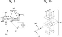
- Fig. 9:
- is a longitudinal cross-section of the sensor device of
Fig. 8 ; and - Fig. 10:
- is an explosive view of a mounting arrangement of the sensor of the sensor device of
Fig. 8 . - An embodiment of a system for producing and handling sausage-like products according to
Fig. 1 comprises as main components a schematically shownproduction line 3 for producing sausage-like products S, like sausages, and storing them on rod-like elements R, like smoking rods, including acontrol unit 160 for controlling theproduction line 3, a handlingrobot 300 having acontrol unit 310 for controlling the movement ofrobot 300, and astorage frame 400, into which the sausages S hung up at the smoking rods R are to be moved. It must be noted, that therobot 300 is not obligatory for the invention, and that the rod-like elements can also be manually moved by a user. Optionally, areject bin 900 may be provided into which a user orrobot 300 may place rod-like elements which are discarded, as described later. -
Production line 3 comprises aclipping machine 100 for producing the sausage-like products S and anautomatic hanging line 200 for loading (storing) the produced sausage-like products S on the smoking rods (rod-like elements)R. Hanging line 200 preferably includes or is combined with anoutfeed device 220 havinghorizontal rails 222 for supporting the rod-like elements R which carry sausage-like products S and leave hangingline 200. -
Control unit 160 ofproduction line 3 andcontrol unit 310 ofrobot 300 may communicate with each other via common techniques like wireless connections or wired connections, in order to coordinate the operations. - When operating the system,
storage frame 400 is positioned in an operating range of handlingrobot 300. Insidestorage frame 400, tray rails or shelf rails e.g. in the form of horizontally aligned support bars 402, 404 are arranged for positioning smoking rods R thereon. - Handling
robot 300 preferably is a so called joined-arm robot. Construction and operation ofsuch robot 300 in such system is described in detail inEP 2 384 638 B1 . - A clipping
machine 100 for producing sausage-shaped products S is schematically shown inFig. 2 , and comprises as main components a fillingtube 10 having a longitudinally extending center axis A and with a discharge opening for a filling material at itsleft end 12 and a feeding opening for the filling material fed to the fillingtube 10 by a feeding pump at itsright end 14, a casing brake assembly 16 arranged coaxially with fillingtube 10 in the region of theleft end 12 of fillingtube 10. Fillingtube 10 is made of a suitable material, like stainless steel. A supply of tubular packaging casing material M made of a thin sheet material is stored on the fillingtube 10. From the supply of tubular packaging casing material M, a single packaging casing is pulled-off during the process of manufacturing the sausage-shaped products S, while the tubular packaging casing material M is retarded by acasing brake 116. Clippingmachine 100 further comprises aclipping device 120 for closing a filled tubular packaging casing M by applying closure means, like closure clips C, to a plait-like portion P, and gathering means 130 for gathering the filled tubular packaging casing M and for forming said plait-like portion P thereto, and which are all arranged downstream fillingtube 10. -
Right end 14 of horizontally arranged fillingtube 10 is coupled to a filler arrangement (not shown) including a pump for feeding filling material through fillingtube 10 in a feeding direction F into tabular packaging casing M closed on its front end facing in the feeding direction F, by a closure clip C. - As it can be inferred from
Fig. 2 , positioned immediately downstreamleft end 12 of fillingtube 10,clipping device 120 is arranged and coaxially aligned to fillingtube 10.Clipping device 120 comprises a first and asecond clipping tool punch 122 and adie 124. It has to be noted thatpunch 122 and die 124 may apply and close a single closure clip C for closing the just filled tubular packaging casing M, or may apply and close two closure clips C at the same time, a first closure clip C for closing the just filled tubular packaging casing M for forming a sausage-shaped product S, and a second closure clip C for closing the front end of the tubular packaging casing M subsequently to be filled. Gathering means 130 includes afirst displacer unit 132 and asecond displacer unit 134, whereinfirst displacer unit 132 is positioned downstreamsecond displacer unit 134. First andsecond clipping tools device 120 may be positioned between first andsecond displacer units - If it is desired to suspend sausage-shaped product on a rod-like element, like a smoking rod, e.g. for further treatment, a suspension element, like a suspension loop SL, may be provided such that suspension loop SL is attached to sausage-shaped product S by means of one of closure clips C. According to
Fig. 1 , suspension loop L is provided in the movement path ofdie 124 such that suspension loop L is engaged by a closure clip C halt indie 124 to be applied to plait-like portion P and attached thereto together with closure clipC. Clipping machine 100 further comprises a conveyingdevice 150 for conveying sausage-shaped product S towards hangingline 200. -
Fig. 3 shows a schematic perspective overview of aproduction line 3 according to the invention. In thisproduction line 3clipping machine 100 is combined with hangingline 200. The produced sausage-shaped products S leaving clippingmachine 100 in transfer direction T, as indicated by arrow T inFig. 3 , are received fromautomatic hanging line 200, which is shown only schematically in an overview with some components (e.g. the loading device) omitted, in order to enhance clarity. Hangingline 200 receives the sausage-shaped products S from clippingmachine 100 and rod-like elements R from amagazine 210, for example, which is attached to aframe 250 of hangingline 200. Hangingline 200 preferably comprises anoutfeed device 220 which comprises two horizontally arrangedrails 222 for supporting the rod-like elements R leaving a loading position of hangingline 200 to anoutput position 224 located at the outermost ends of rails 222 (i.e. the front ends inFig. 3 ). InFig. 3 , the loading position (not depicted since the loading device 260 is not shown) resides on the opposite, i.e. inner ends ofrails 222. - As shown in
Fig. 4 , eachrail 222 ofoutfeed device 220 comprises a circulating chain 223 configured to engage and move one of the ends E1, E2 of rod-like element R towards the output position. As shown inFig. 4 ,magazine 210 may comprise anupstream wall 212 and a downstream wall 214 (with respect to the transfer direction T), which are arranged parallel to each other and approximately vertically above rails 222. The distance betweenwalls walls vertical slots 216 are arranged parallel to each other.Slots 216 extend from the upper end ofwalls magazine 210 move intoslots 216 and sequentially move to the funnel-shaped recess.Magazine 210 further comprises releasing means (not shown) for blocking the rod-like elements R positioned inslots 216, and for selectively releasing a single rod-like element R from one ofslots 216 at the lower ends ofslots 216. At the lower end of each funnel-shaped recess, asingle slot 218 is arranged into which single rod-like element R is moved after being selectively released fromslots 216.Slots 218 provide a standby position in which a single, empty rod-like element R is kept ready for being fed into the loading position after a filled rod-like element R has been removed out of the loading position. - Immediately below
single slots 218, second blocking and releasing elements 434 in the form of release pins are arranged for securing a single rod-like element R in the standby position, and for releasing rod-like element R for further feeding towards the loading position. - The general construction and operation of
magazine 210 andoutfeed device 220 are known and described inEP 3 241 447 A1 - According to a first embodiment,
magazine 210 comprises afirst support element 202 configured to receive the first end E1 of a rod-like element R and asecond support element 204 configured to receive the second end E2 of the rod-like element R. The first andsecond support elements Support elements slots 218, so that a rod-likeelement leaving slots 218 is fed ontosupport elements Fig. 4 , only the location ofsupport element 202 ofwall 212 is indicated, whilesupport element 204 is located in theopposite wall 214.Support elements Fig. 7 below. A sensor device as shown inFig. 8 and described later can be arranged at one of thesupport elements support elements walls elements line 200, while the second output path leads out ofmagazine 210 and hangingline 200 so that the rod-like element R can be discarded and received in areject bin 900 located beneathmagazine 210, for example. - In the following, a method of operating the first embodiment is described. In a first step, one of the rod-like elements R is fed by
magazine 210 fromslots 218 to the measuring position formed bysupport elements sensor device 240. In a third step,sensor device 240 generates an electric signal which is used bycontrol unit 160 to determine the length L. In a fourth step,control unit 160 determines whether the length L is within a predetermined tolerance range of a desired length Ld. If it is determined in the fourth step that the length L is within the tolerance range of Ld, the processing advances to a fifth step, in which the rod-like element R is transferred via the first output path ofmagazine 210 to the loading position defined by third andfourth support elements line 200 and a predetermined number of the produced sausage-shaped products S is loaded on the rod-like element R (as described later herein and shown inFigs. 6 and7 ), whereupon the filled rod-like element R is removed from the loading position and transferred to the output position byoutfeed device 220. The processing then returns to the first step. - However, in case it is determined in the fourth step that the length L is not within the tolerance range of Ld, the processing advances to a sixth step, in which the rod-like element R is discarded and transferred via the second output path out of hanging
line 200 and, for example, into thereject bin 900. The processing then returns to the first step. - In the following, a second embodiment of the invention is described with reference to
Figs. 5 to 7 . The second embodiment differs from the first embodiment in thatmagazine 210 does not include the measuring position with first andsecond support elements sensor device 240 and the slot switches and first and second output paths as described above. Instead,magazine 210 includes only one output path leading to the loading position of hangingline 200. -
Fig. 5 is a top view showing the main components of hangingline 200, andFig. 6 is a side view of the hangingline 200 ofFig. 5. Figs. 5 and6 particularly show theloading device 270 which is supported byframe 250 of hangingline 200 and located at the inner ends ofrails 222 of theoutfeed device 220 and above a rod-like element R placed in the loading position.Loading device 270 per se is well-known and can have different configurations.Loading device 270, as shown, comprises atransfer device 272 and a circulatingloading chain 274 carryingengagement elements 276. - Additionally,
loading device 270 comprises third andfourth support elements fourth support elements second support elements fourth support elements sensor device 240 is attached tothird support element 206. -
Transfer device 272 is configured to catch suspension loop SL of the sausage-like product S leaving clippingmachine 100, and to deliver suspension loop SL via aslip 273 to rod-like element R resting with its second end E2 onfourth support element 208. While sliding on slip 271, suspension loop SL is engaged byengagement elements 276 circulating withchain 274, and thus, moved over the left end ofslip 273 onto rod-like element R.Fourth support element 208 is attached to the left end ofslip 273, as is best shown inFig. 7 , and retains second end E2 of rod-like element R in lateral directions aligned withslip 273. Moreover, second end E2 of rod-like element R should abut to the end surface ofslip 273, which end surface is astop 209 offourth support element 208, so as to avoid any gap between rod-like element R and slip 273 for ensuring smooth transition of suspension loop SL. This alignment of rod-like element R withstop 209 ofsupport element 208 advantageously can be performed by a pushingelement 242 ofsensor element 240 described below. - An exemplary embodiment of
sensor element 240 is described in the following with respect toFigs. 8 to 10 .Sensor element 240 comprises aframe 241 to be fixedly attached with respect tothird support element 206, and a pushingdevice 242 carried byframe 241. Pushingdevice 242 comprises aram 244 guided in the axial direction of axis A of rod-like element R by alinear feed 245 having posts guided in longitudinal holes of frame 241 (seeFig. 8 ). InFig. 8 ,ram 244 is shown without a contact element, while inFig. 9 , a contact element, preferable made of plastic or hard rubber or the like, is attached to the front face ofram 244 which is intended to engage first end E1 of rod-likeelement R. ram 244 is coupled via a piston rod with a piston (not shown) of apneumatic cylinder 248, so thatram 244 can be moved in the direction of axis A of rod-like elementR. Pneumatic cylinder 248 is attached to frame 241. Aclamping device 247 is attached topneumatic cylinder 248 such that it encloses and clamps asensor 246 to a location in the vicinity ofpneumatic cylinder 248 which is mad of non-magnetic material, so thatsensor 246 can detect a magnetic field generated by a magnetic element included in the piston or the piston rod of pushingdevice 242. For example,sensor 246 is a Hall-Sensor or a magneto-resistive sensor or the like, and depending on the position of the magnetic element contained in the piston or in the piston rod of pushingelement 242,sensor 246 generates a varying electrical signal.Control unit 160 can then receive this electrical signal from sensor 246 acable 243 and determine the position of the piston based on the electrical signal. Thus, also the position ofram 244 can be determined, and since the fixed distance between third andfourth support elements control unit 160 can calculate the actual distance between the end face of the contact element ofram 244 and the surface ofstop 209 offourth support element 208. This distance corresponds to the length L of rod-like element R placed in the loading (or measuring) position whenram 244 pushes against first end E1 of rod-like element R and second end E2 of the same abuts on (i.e. is aligned with)stop 209. Thus, length L of rod-like element R can be determined. - In this manner,
sensor element 240 is capable of performing two functions simultaneously, namely aligning second end E2 of rod-like element R withstop 209 and slip 273, respectively, as well as measuring the length L of rod-like element R. - It must be noted, that the invention is not restricted to a magnetic sensor. Instead, also other position sensors can be used, such as optical sensors. Moreover, the invention is not restricted to pushing
device 242 havingpneumatic cylinder 248, but can also be implemented with aram 244 driven electrically such as by a solenoid or the like.Sensor device 240 described above can be used in the above described first embodiment, when attached tofirst support element 202. In this case,second support element 204 also has a stop similar to stop 209 offourth support element 208. - In the following, a method of operating the second embodiment is described. In a first step, one of the rod-like elements R is fed by
magazine 210 to the measuring position, which in this case corresponds to the loading position defined by third andfourth support elements sensor device 240, while aligning rod-like element to stop 209 offourth support element 208 atslip 273. In a third step,sensor device 240 generates an electric signal which is used bycontrol unit 160 to determine the length L. In a fourth step,control unit 160 determines whether the length L is within a predetermined tolerance range of a desired length Ld. If it is determined in the fourth step that the length L is within the tolerance range of Ld, the processing advances to a fifth step, in which a predetermined number of the produced sausage-shaped products S is loaded on the rod-like element R byloading device 270, whereupon the filled rod-like element R is removed from the loading position and transferred to the output position byoutfeed device 220. The processing then returns to the first step. - However, in case it is determined in the fourth step that the length L is not within the tolerance range of Ld, the processing advances to a sixth step, in which the rod-like element R is discarded and transferred to the output position by
outfeed device 220, whereupon the discarded rod-like element R must be removed either by a user or byrobot 300. The processing then returns to the first step. - In case the discarded rod-like element R is manually removed by a user, the system can stop the clipping machine and/or the hanging line until the user confirms removal of the discarded rod-like element R. This avoids that sausage-like products S are produced which cannot be moved further along the production process. In case the system comprises the handling
robot 300, the discarded rod-like element R can be removed from the output position ofoutfeed device 220 byrobot 300, and can be placed in thereject bin 900, for example. Thus, the production process can be smoothly continued. - Since
control unit 160 ofproduction line 3 determines the length of rod-like element R, this length can be used by handlingrobot 300 to optimize the placing position of rod-like element R onstorage frame 400. In particular,control device 160 can transmit the value of length L of rod-like element R currently presented in the output position ofoutfeed device 220 to controlunit 310 of handlingrobot 300. Simultaneously, the longitudinal position of rod-like element R in the output position is well defined due to the alignment of rod-like element R in the loading position, if it is assumed that during the outfeed operation of outfeed device the axial position is not considerably changed. It is also possible, to provide a further alignment device (not shown) at the output position to ensure a well defined axial position of rod-like element R. In this way, handlingrobot 300 is able to grip rod-like element R at the output position in a well known distance from both ends E1, E2 of rod-like element R, so that the handlingrobot 300 is further able to place rod-like element R perpendicular to and onsupport bars storage frame 400 such that both ends E1, E2 overlap support bars 402, 404 by the same amount. In other words, handlingrobot 300 can place rod-like element R centred onsupport bars storage frame 400 and reduces the risk of slipping off from the support bars 402, 404 whenstorage frame 400 is subject to vibrations or shock. -
Sensor device 240 attached to one of the support elements of the loading position can also be added to hanginglines 200 already in operation, so that all the advantages described above can be added to older systems whencontrol unit 160 ofproduction line 3 and, if applicable,control unit 310 of handlingrobot 300 are reprogrammed accordingly so as to perform the methods of the invention. -
- A
- center axis of rod-like element
- C
- closure clip
- E1
- first end of rod-like element
- E2
- second end of rod-like element
- F
- feeding direction
- M
- casing material
- P
- plait-like portion
- R
- rod-like element
- S
- sausage-shaped product
- SL
- suspension loop
- T
- transfer direction
- 1
- system
- 3
- production line
- 10
- filling tube
- 12
- downstream end of filling tube
- 14
- upstream end of filling tube
- 100
- clipping machine
- 116
- casing brake
- 120
- clipping device
- 122
- punch
- 124
- die
- 130
- gathering means
- 132
- first displacer unit
- 134
- second displacer unit
- 150
- conveying device
- 160
- control unit of production line
- 200
- hanging line
- 202
- first support element
- 204
- second support element
- 206
- third support element
- 208
- fourth support element
- 209
- stop
- 210
- magazine
- 212
- upstream wall
- 214
- downstream wall
- 216
- slots
- 218
- single slot
- 220
- outfeed device
- 222
- rail
- 223
- outfeed chain
- 224
- output position
- 240
- sensor device
- 241
- frame of sensor device
- 242
- pushing device
- 243
- cable
- 244
- ram
- 245
- linear feed
- 246
- sensor
- 247
- clamping device
- 248
- pneumatic cylinder
- 250
- frame of hanging line
- 270
- loading device
- 272
- transfer device
- 273
- slip
- 274
- loading chain
- 276
- engagement element
- 300
- handling robot
- 310
- control unit of handling robot
- 400
- storage frame
- 402
- support bar
- 404
- support bar
- 900
- reject bin
Claims (15)
- A method for handling longitudinal rod-like elements (R), in particular smoking rods, for storing sausage-shaped products (S), in particular sausages, in a system (1) for producing and handling the sausage-shaped products (S), wherein the method comprises the steps of:providing a plurality of the rod-like elements (R), each rod-like element (R) having a length (L) defined between a first end (E1) and a second end (E2);providing a clipping machine (100) configured to produce the sausage-shaped products (S);providing a hanging line (200) configured to load the produced sausage-shaped products (S) on the rod-like elements (R) and comprising a measuring position for receiving the rod-like elements (R) and for measuring the length (L) of the rod-like elements (R), and a loading position for receiving the rod-like elements (R) and for loading the produced sausage-shaped products (S) on the rod-like elements (R), wherein the measuring position is defined by a first support element (202) configured to receive the first end (E1) of one of the rod-like elements (R) and a second support element (204) configured to receive the second end (E2) of the one of the rod-like elements (R), and wherein the loading position is defined by a third support element (206) configured to receive the first end (E1) of the one of the rod-like elements (R) and a fourth support element (208) configured to receive the second end (E2) of the one of the rod-like elements (R);feeding one of the rod-like elements (R) to the measuring position of the hanging line (200);measuring the length (L) of said one of the rod-like elements (R) by a sensor device (240);determining by a control unit (160) whether the length (L) is within a tolerance range of a desired length (Ld);providing said one of the rod-like elements (R) in the loading position of the hanging line (200) and loading a predetermined number of the produced sausage-shaped products (S) on said one of the rod-like elements (R), if the length (L) is within the tolerance range;discarding said one of the rod-like elements (R) from the hanging line (200), if the length (L) is not within the tolerance range.
- The method of claim 1, wherein the hanging line (200) further comprises a magazine (210) for holding available the plurality of the rod-like elements (R), wherein the measuring position of the hanging line (200) is located within the magazine (210), and wherein the step of discarding comprises removing the one of the rod-like elements (R) from the measuring position directly into a reject bin (900).
- The method of claim 1, wherein in the hanging line (200) the measuring position and the loading position are one and the same, so that the step of measuring is performed with the one of the rod-like elements (R) placed in the loading position.
- The method of claim 3, wherein the hanging line further comprises an outfeed device (220), and wherein the method further comprises the step of moving the one of the rod-like elements (R) by the outfeed device (220) from the loading position to an output position.
- The method of claim 4, wherein the step of discarding comprises removing the one of the rod-like elements (R) from the output position.
- The method of one of the preceding claims, wherein the step of discarding further comprises stopping the operation of the clipping machine (100) until a next one of the rod-like elements (R) has been placed in the loading position of the hanging line (200) and its length (L) has been determined to be within the tolerance range.
- The method of claim 6, wherein the step of discarding further comprises deferring the step of feeding the next one of the rod-like elements (R) to the loading position of the hanging line (200) until a user manually removes the discarded rod-like element (R) and confirms the removal to the system (1).
- The method of one of the claims 1 to 6, wherein the system further comprises a handling robot (300) configured to grip and move the one of the rod-like elements (R), whereinthe handling robot (300) grips the rod-like element (R), which is loaded with the predetermined number of the produced sausage-shaped products (S), and places the rod-like element (R) in a storage frame (400), if the length (L) is within the tolerance range;wherein the step of discarding further comprises removing the discarded rod-like element (R) and placing the same in a reject bin (900) by the handling robot (300).
- The method of claim 8, wherein the storage frame comprises two support bars (402, 404) having a distance (D) smaller than the desired length (Ld), and wherein the handling robot (300) places the one of the rod-like elements (R) on the support bars (402, 404) and perpendicular to the same such that both ends (E1, E2) overlap the support bars (402, 404) by the same amount, if the length (L) is within the tolerance range.
- A system (1) for producing sausage-shaped products (S), like sausages, containing a flowable filling material in a tubular or bag-shaped packaging casing (M) and a suspension element (SL) such as a suspension loop, and for loading the produced sausage-shaped products (S) on rod-like elements (R) such as smoking rods, each rod-like element (R) having a length (L) defined between a first end (E1) and a second end (E2); the system (1) comprising:a clipping machine (100) configured to produce the sausage-shaped products (S);a hanging line (200) configured to load the produced sausage-shaped products (S) on the rod-like elements (R); anda control unit (160) controlling the operation of the clipping machine (100) and the hanging line (200);wherein the hanging line (200) comprises:a first support element (202) configured to receive the first end (E1) of one of the rod-like elements (R) and a second support element (204) configured to receive the second end (E2) of the one of the rod-like elements (R), the first and second support elements (202, 204) defining a measuring position; anda third support element (206) configured to receive the first end (E1) of the one of the rod-like elements (R) and a fourth support element (208) configured to receive the second end (E2) of the one of the rod-like elements (R), the third and fourth support elements (206, 208) defining a loading position for loading the produced sausage-shaped products (S) on the rod-like elements (R);a sensor device (240) arranged at the measuring position and configured to measure the length (L) of the one of the rod-like elements (R) placed in the measuring position;wherein the control unit (160) is configured to compare the length (L) with a desired length (Ld) and to determine whether the length is within a tolerance range of the desired length (Ld), and wherein the control unit (160) further causes the hanging line (200) to load a predetermined number of sausage-shaped products (S) on the one of the rod-like elements (R) if the length (L) is within the tolerance range, and causes discarding the one of the rod-like elements (R) if the length (L) is not within the tolerance range.
- The system (1) of claim 10, wherein the hanging line (200) further comprises a magazine (210) for holding available a plurality of the rod-like elements (R), wherein the first and second support elements (202, 204) defining the measuring position are located within the magazine (210), and wherein the magazine (210) is configured to successively feed single rod-like elements (R) first to the measuring position and then to the loading position or to a reject bin (900).
- The system (1) of claim 10, wherein the first and third support elements (202, 206) are one and the same and the second and fourth support elements (204, 208) are one and the same, so that the measuring position is identical with the loading position and the sensor device (240) is arranged at the loading position; and wherein the hanging line further comprises an outfeed device (220) configured to move the one of the rod-like elements (R) from the loading position to an output position.
- The system (1) of one of the claims 10 to 12, further comprisinga storage frame (400) having two support bars (402, 404) with a distance (D) smaller than the desired length (Ld) for carrying a plurality of the rod-like elements (R); anda handling robot (300) configured to grip the one of the rod-like elements (R) and to place it on the support bars (402, 404) of the storage frame (400) or in a reject bin (900);wherein the handling robot (300) is further configured to receive the measured length (L) of the one of the rod-like elements (R) from the control unit (160) and to adjust the placing position of the one of the rod-like elements (R) on the support bars (402, 404) such that both ends (E1, E2) overlap the support bars (402, 404) by the same amount.
- The system (1) of one of the claims 10 to 13, whereinthe sensor device (240) comprises a pushing device (242) arranged at the third support element (206) and having a ram (244) configured to push against the first end (E1) in a longitudinal direction of the one of the rod-like elements (R), so that the second end (E2) becomes aligned with the fourth support element (208) having a stop (209);wherein the pushing device (242) comprises a sensor (246) configured to detect a position of the ram (244) and to generate an output signal depending on the position of the ram (244); andwherein the control unit (160) is configured to receive the output signal of the sensor (246) and to determine the length (L) of the one of the rod-like elements (R) based on the signal when the second end (E2) is aligned with the fourth support element (208).
- The system (1) of claim 14, wherein the pushing device (242) comprises a pneumatic cylinder (248) fixedly attached with respect to the third support element (206) and a piston having a magnetic element and coupled to the ram (244), and wherein the sensor (246) is a magnetic sensor, in particular a Hall-Sensor, attached to the pneumatic cylinder (248) and configured to detect an axial position of the piston.
Priority Applications (2)
| Application Number | Priority Date | Filing Date | Title |
|---|---|---|---|
| EP22172758.9A EP4275505B1 (en) | 2022-05-11 | 2022-05-11 | Hanging line with smoking rod length measurement |
| US18/195,672 US12161129B2 (en) | 2022-05-11 | 2023-05-10 | Hanging line with smoking rod length measurement |
Applications Claiming Priority (1)
| Application Number | Priority Date | Filing Date | Title |
|---|---|---|---|
| EP22172758.9A EP4275505B1 (en) | 2022-05-11 | 2022-05-11 | Hanging line with smoking rod length measurement |
Publications (2)
| Publication Number | Publication Date |
|---|---|
| EP4275505A1 EP4275505A1 (en) | 2023-11-15 |
| EP4275505B1 true EP4275505B1 (en) | 2025-01-29 |
Family
ID=81603610
Family Applications (1)
| Application Number | Title | Priority Date | Filing Date |
|---|---|---|---|
| EP22172758.9A Active EP4275505B1 (en) | 2022-05-11 | 2022-05-11 | Hanging line with smoking rod length measurement |
Country Status (2)
| Country | Link |
|---|---|
| US (1) | US12161129B2 (en) |
| EP (1) | EP4275505B1 (en) |
Families Citing this family (1)
| Publication number | Priority date | Publication date | Assignee | Title |
|---|---|---|---|---|
| CN120839479B (en) * | 2025-09-23 | 2025-11-28 | 浙江科腾精工机械股份有限公司 | An automatic assembly and processing device for combination bolts |
Citations (5)
| Publication number | Priority date | Publication date | Assignee | Title |
|---|---|---|---|---|
| DE3930876C1 (en) | 1989-09-15 | 1990-07-26 | Guenter 6080 Gross-Gerau De Kollross | |
| DE202006019883U1 (en) | 2006-09-06 | 2007-05-03 | Poly-Clip System Gmbh & Co. Kg | Production line for production of sausages shaped products, has control device is provided in position to regulate speed of conveying element of the loading machine on basis of control variable derived from clipping |
| EP1891858A1 (en) | 2006-08-22 | 2008-02-27 | Tipper Tie Alpina AG | Bar changing device in a transfer device for hanging packaging units |
| WO2011134096A1 (en) | 2010-04-30 | 2011-11-03 | Tipper Tie Alpina Gmbh | Stick feeding unit on a suspension device for sausage-type packagings |
| EP2384638A1 (en) | 2010-05-04 | 2011-11-09 | Poly-clip System GmbH & Co. KG | Robotic device for inserting or removing rod-like elements |
Family Cites Families (3)
| Publication number | Priority date | Publication date | Assignee | Title |
|---|---|---|---|---|
| US6104959A (en) * | 1997-07-31 | 2000-08-15 | Microwave Medical Corp. | Method and apparatus for treating subcutaneous histological features |
| ES3046187T3 (en) | 2016-05-04 | 2025-12-01 | Poly Clip System Gmbh & Co Kg | Direct hanging line |
| EP3732982B1 (en) * | 2019-04-29 | 2023-09-27 | Poly-clip System GmbH & Co. KG | Removal device for rod-like elements |
-
2022
- 2022-05-11 EP EP22172758.9A patent/EP4275505B1/en active Active
-
2023
- 2023-05-10 US US18/195,672 patent/US12161129B2/en active Active
Patent Citations (5)
| Publication number | Priority date | Publication date | Assignee | Title |
|---|---|---|---|---|
| DE3930876C1 (en) | 1989-09-15 | 1990-07-26 | Guenter 6080 Gross-Gerau De Kollross | |
| EP1891858A1 (en) | 2006-08-22 | 2008-02-27 | Tipper Tie Alpina AG | Bar changing device in a transfer device for hanging packaging units |
| DE202006019883U1 (en) | 2006-09-06 | 2007-05-03 | Poly-Clip System Gmbh & Co. Kg | Production line for production of sausages shaped products, has control device is provided in position to regulate speed of conveying element of the loading machine on basis of control variable derived from clipping |
| WO2011134096A1 (en) | 2010-04-30 | 2011-11-03 | Tipper Tie Alpina Gmbh | Stick feeding unit on a suspension device for sausage-type packagings |
| EP2384638A1 (en) | 2010-05-04 | 2011-11-09 | Poly-clip System GmbH & Co. KG | Robotic device for inserting or removing rod-like elements |
Non-Patent Citations (19)
| Title |
|---|
| D1 - RECHNUNG 5903.012.501 DÖLLING (04.02.2022) |
| D10 - Video Messevorführung SwiStickXXL (18.10.2012) |
| D10A - STANDBILDER AUS VIDEODOKUMENT D10 (18.10.2012) |
| D11 - AUFTRAGSBESTÄTIGUNG 21368306 VISCOFAN (06.06.2019) |
| D12 - CHECKLISTE MASCHINENMONTAGE 5900.008.349 VISCOFAN (30.09.2019) |
| D13 - BETRIEBSANLEITUNG SWISTICK S/M/L (10.07.2019) |
| D14 - AUFTRAGSBESTÄTIGUNG 21320977 SUTTERO (02.11.2016) |
| D15 - CHECKLISTE MASCHINENMONTAGE 5900002097 SUTTERO (31.03.2017) |
| D16 - AUFTRAGSBESTÄTIGUNG 21333983 BRANDENBURG (13.07.2017) |
| D17 - ERSATZTEILKATALOG SWISTICK SML (16.09.2019) |
| D2 - Auftragsbestätigung 21401129 Dölling (19.05.2021) |
| D3 - CHECKLISTE MASCHINENMONTAGE 5903.012.501 DÖLLING (03.02.2022) |
| D4 - BETRIEBSANLEITUNG SWISTICK XXL 5903012501 (14.12.2021) |
| D5 - ERSATZTEILKATALOG SWISTICK XXL 5903012501 (15.12.2021) |
| D6A - STANDBILDER AUS VIDEODOKUMENT D6 (10.05.2021) |
| D7 - TRANSPORTSCHEIN 859.502 STOCKMEYER (23.05.2018) |
| D8 - RECHNUNG 859.506 MULTIVAC (30.11.2016) |
| D9 - RECHNUNG 859.507 MULTIVAC (30.11.2016) |
| VISCOFAN FOOD PROCESSING AND PACKAGING SOLUTIONS : "Tipper Tie Swistick XXL. VISCOFAN GLOBUS AUSTRALIA.", 9 May 2021 (2021-05-09), XP093334709, Retrieved from the Internet <URL:https://www.youtube.com/watch?v=86jMx0i3K90> |
Also Published As
| Publication number | Publication date |
|---|---|
| US12161129B2 (en) | 2024-12-10 |
| EP4275505A1 (en) | 2023-11-15 |
| US20230363400A1 (en) | 2023-11-16 |
Similar Documents
| Publication | Publication Date | Title |
|---|---|---|
| EP2384638B1 (en) | Robotic device and method for inserting or removing rod-like elements | |
| JP4914320B2 (en) | Method and apparatus for separating rod-shaped body | |
| EP2363027B2 (en) | System and method for allowing a quality check of sausage-shaped products | |
| US8366522B2 (en) | System and method for weighing products | |
| US12161129B2 (en) | Hanging line with smoking rod length measurement | |
| US7766729B2 (en) | Smoking rail feed means and method of accurately feeding the same | |
| JPH07196257A (en) | Bobbin tube supply device | |
| JP2000500977A (en) | Conveyor system for bar-shaped articles | |
| JP2003188579A (en) | Electronic package removal apparatus and method | |
| EP2792903B1 (en) | Automatic dispenser for balancing weights | |
| EP2384640B1 (en) | Separation device and method | |
| US11793206B2 (en) | Removal device for rod-like elements | |
| JP2005112365A (en) | Movable holder, and automatic bagging apparatus using the same | |
| EP3858143B1 (en) | Transfer device with a buffer for rod-like elements and method for controlling the transfer device | |
| EP4272567B1 (en) | System for producing sausage-shaped products | |
| CN107105681B (en) | Device and method for shifting fish | |
| IT202000013987A1 (en) | MACHINE FOR PACKAGING GROUPS OF TISSUE PRODUCTS AND METHOD OF CHECKING CONFORMITY OF LAYERS OF GROUPS OF TISSUE PRODUCTS | |
| EP4272566B1 (en) | Filling tube assembly of a clipping machine, system and method for producing sausage-shaped products | |
| CN119498557A (en) | Device for processing rod-shaped products and method for first filling of such a device |
Legal Events
| Date | Code | Title | Description |
|---|---|---|---|
| PUAI | Public reference made under article 153(3) epc to a published international application that has entered the european phase |
Free format text: ORIGINAL CODE: 0009012 |
|
| STAA | Information on the status of an ep patent application or granted ep patent |
Free format text: STATUS: THE APPLICATION HAS BEEN PUBLISHED |
|
| AK | Designated contracting states |
Kind code of ref document: A1 Designated state(s): AL AT BE BG CH CY CZ DE DK EE ES FI FR GB GR HR HU IE IS IT LI LT LU LV MC MK MT NL NO PL PT RO RS SE SI SK SM TR |
|
| STAA | Information on the status of an ep patent application or granted ep patent |
Free format text: STATUS: REQUEST FOR EXAMINATION WAS MADE |
|
| 17P | Request for examination filed |
Effective date: 20240515 |
|
| RBV | Designated contracting states (corrected) |
Designated state(s): AL AT BE BG CH CY CZ DE DK EE ES FI FR GB GR HR HU IE IS IT LI LT LU LV MC MK MT NL NO PL PT RO RS SE SI SK SM TR |
|
| GRAP | Despatch of communication of intention to grant a patent |
Free format text: ORIGINAL CODE: EPIDOSNIGR1 |
|
| STAA | Information on the status of an ep patent application or granted ep patent |
Free format text: STATUS: GRANT OF PATENT IS INTENDED |
|
| RIC1 | Information provided on ipc code assigned before grant |
Ipc: A22C 15/00 20060101AFI20240801BHEP |
|
| INTG | Intention to grant announced |
Effective date: 20240826 |
|
| GRAS | Grant fee paid |
Free format text: ORIGINAL CODE: EPIDOSNIGR3 |
|
| GRAA | (expected) grant |
Free format text: ORIGINAL CODE: 0009210 |
|
| STAA | Information on the status of an ep patent application or granted ep patent |
Free format text: STATUS: THE PATENT HAS BEEN GRANTED |
|
| AK | Designated contracting states |
Kind code of ref document: B1 Designated state(s): AL AT BE BG CH CY CZ DE DK EE ES FI FR GB GR HR HU IE IS IT LI LT LU LV MC MK MT NL NO PL PT RO RS SE SI SK SM TR |
|
| REG | Reference to a national code |
Ref country code: GB Ref legal event code: FG4D |
|
| REG | Reference to a national code |
Ref country code: CH Ref legal event code: EP |
|
| P01 | Opt-out of the competence of the unified patent court (upc) registered |
Free format text: CASE NUMBER: APP_2548/2025 Effective date: 20250115 |
|
| REG | Reference to a national code |
Ref country code: DE Ref legal event code: R096 Ref document number: 602022009956 Country of ref document: DE |
|
| REG | Reference to a national code |
Ref country code: IE Ref legal event code: FG4D |
|
| REG | Reference to a national code |
Ref country code: NL Ref legal event code: MP Effective date: 20250129 |
|
| PG25 | Lapsed in a contracting state [announced via postgrant information from national office to epo] |
Ref country code: NL Free format text: LAPSE BECAUSE OF FAILURE TO SUBMIT A TRANSLATION OF THE DESCRIPTION OR TO PAY THE FEE WITHIN THE PRESCRIBED TIME-LIMIT Effective date: 20250129 |
|
| PG25 | Lapsed in a contracting state [announced via postgrant information from national office to epo] |
Ref country code: RS Free format text: LAPSE BECAUSE OF FAILURE TO SUBMIT A TRANSLATION OF THE DESCRIPTION OR TO PAY THE FEE WITHIN THE PRESCRIBED TIME-LIMIT Effective date: 20250429 |
|
| PG25 | Lapsed in a contracting state [announced via postgrant information from national office to epo] |
Ref country code: FI Free format text: LAPSE BECAUSE OF FAILURE TO SUBMIT A TRANSLATION OF THE DESCRIPTION OR TO PAY THE FEE WITHIN THE PRESCRIBED TIME-LIMIT Effective date: 20250129 |
|
| PG25 | Lapsed in a contracting state [announced via postgrant information from national office to epo] |
Ref country code: PL Free format text: LAPSE BECAUSE OF FAILURE TO SUBMIT A TRANSLATION OF THE DESCRIPTION OR TO PAY THE FEE WITHIN THE PRESCRIBED TIME-LIMIT Effective date: 20250129 |
|
| PGFP | Annual fee paid to national office [announced via postgrant information from national office to epo] |
Ref country code: DE Payment date: 20250606 Year of fee payment: 4 |
|
| PG25 | Lapsed in a contracting state [announced via postgrant information from national office to epo] |
Ref country code: ES Free format text: LAPSE BECAUSE OF FAILURE TO SUBMIT A TRANSLATION OF THE DESCRIPTION OR TO PAY THE FEE WITHIN THE PRESCRIBED TIME-LIMIT Effective date: 20250129 |
|
| REG | Reference to a national code |
Ref country code: LT Ref legal event code: MG9D |
|
| PG25 | Lapsed in a contracting state [announced via postgrant information from national office to epo] |
Ref country code: NO Free format text: LAPSE BECAUSE OF FAILURE TO SUBMIT A TRANSLATION OF THE DESCRIPTION OR TO PAY THE FEE WITHIN THE PRESCRIBED TIME-LIMIT Effective date: 20250429 Ref country code: IS Free format text: LAPSE BECAUSE OF FAILURE TO SUBMIT A TRANSLATION OF THE DESCRIPTION OR TO PAY THE FEE WITHIN THE PRESCRIBED TIME-LIMIT Effective date: 20250529 |
|
| REG | Reference to a national code |
Ref country code: AT Ref legal event code: MK05 Ref document number: 1762512 Country of ref document: AT Kind code of ref document: T Effective date: 20250129 |
|
| PG25 | Lapsed in a contracting state [announced via postgrant information from national office to epo] |
Ref country code: HR Free format text: LAPSE BECAUSE OF FAILURE TO SUBMIT A TRANSLATION OF THE DESCRIPTION OR TO PAY THE FEE WITHIN THE PRESCRIBED TIME-LIMIT Effective date: 20250129 |
|
| PG25 | Lapsed in a contracting state [announced via postgrant information from national office to epo] |
Ref country code: PT Free format text: LAPSE BECAUSE OF FAILURE TO SUBMIT A TRANSLATION OF THE DESCRIPTION OR TO PAY THE FEE WITHIN THE PRESCRIBED TIME-LIMIT Effective date: 20250529 Ref country code: LV Free format text: LAPSE BECAUSE OF FAILURE TO SUBMIT A TRANSLATION OF THE DESCRIPTION OR TO PAY THE FEE WITHIN THE PRESCRIBED TIME-LIMIT Effective date: 20250129 |
|
| PG25 | Lapsed in a contracting state [announced via postgrant information from national office to epo] |
Ref country code: BG Free format text: LAPSE BECAUSE OF FAILURE TO SUBMIT A TRANSLATION OF THE DESCRIPTION OR TO PAY THE FEE WITHIN THE PRESCRIBED TIME-LIMIT Effective date: 20250129 Ref country code: GR Free format text: LAPSE BECAUSE OF FAILURE TO SUBMIT A TRANSLATION OF THE DESCRIPTION OR TO PAY THE FEE WITHIN THE PRESCRIBED TIME-LIMIT Effective date: 20250430 |
|
| PG25 | Lapsed in a contracting state [announced via postgrant information from national office to epo] |
Ref country code: AT Free format text: LAPSE BECAUSE OF FAILURE TO SUBMIT A TRANSLATION OF THE DESCRIPTION OR TO PAY THE FEE WITHIN THE PRESCRIBED TIME-LIMIT Effective date: 20250129 |
|
| PG25 | Lapsed in a contracting state [announced via postgrant information from national office to epo] |
Ref country code: SE Free format text: LAPSE BECAUSE OF FAILURE TO SUBMIT A TRANSLATION OF THE DESCRIPTION OR TO PAY THE FEE WITHIN THE PRESCRIBED TIME-LIMIT Effective date: 20250129 |
|
| PG25 | Lapsed in a contracting state [announced via postgrant information from national office to epo] |
Ref country code: SM Free format text: LAPSE BECAUSE OF FAILURE TO SUBMIT A TRANSLATION OF THE DESCRIPTION OR TO PAY THE FEE WITHIN THE PRESCRIBED TIME-LIMIT Effective date: 20250129 |
|
| PG25 | Lapsed in a contracting state [announced via postgrant information from national office to epo] |
Ref country code: DK Free format text: LAPSE BECAUSE OF FAILURE TO SUBMIT A TRANSLATION OF THE DESCRIPTION OR TO PAY THE FEE WITHIN THE PRESCRIBED TIME-LIMIT Effective date: 20250129 |
|
| PG25 | Lapsed in a contracting state [announced via postgrant information from national office to epo] |
Ref country code: IT Free format text: LAPSE BECAUSE OF FAILURE TO SUBMIT A TRANSLATION OF THE DESCRIPTION OR TO PAY THE FEE WITHIN THE PRESCRIBED TIME-LIMIT Effective date: 20250129 |
|
| PG25 | Lapsed in a contracting state [announced via postgrant information from national office to epo] |
Ref country code: EE Free format text: LAPSE BECAUSE OF FAILURE TO SUBMIT A TRANSLATION OF THE DESCRIPTION OR TO PAY THE FEE WITHIN THE PRESCRIBED TIME-LIMIT Effective date: 20250129 Ref country code: CZ Free format text: LAPSE BECAUSE OF FAILURE TO SUBMIT A TRANSLATION OF THE DESCRIPTION OR TO PAY THE FEE WITHIN THE PRESCRIBED TIME-LIMIT Effective date: 20250129 |
|
| PG25 | Lapsed in a contracting state [announced via postgrant information from national office to epo] |
Ref country code: RO Free format text: LAPSE BECAUSE OF FAILURE TO SUBMIT A TRANSLATION OF THE DESCRIPTION OR TO PAY THE FEE WITHIN THE PRESCRIBED TIME-LIMIT Effective date: 20250129 |
|
| PG25 | Lapsed in a contracting state [announced via postgrant information from national office to epo] |
Ref country code: SK Free format text: LAPSE BECAUSE OF FAILURE TO SUBMIT A TRANSLATION OF THE DESCRIPTION OR TO PAY THE FEE WITHIN THE PRESCRIBED TIME-LIMIT Effective date: 20250129 |
|
| REG | Reference to a national code |
Ref country code: DE Ref legal event code: R026 Ref document number: 602022009956 Country of ref document: DE |
|
| PLBI | Opposition filed |
Free format text: ORIGINAL CODE: 0009260 |
|
| REG | Reference to a national code |
Ref country code: CH Ref legal event code: L10 Free format text: ST27 STATUS EVENT CODE: U-0-0-L10-L00 (AS PROVIDED BY THE NATIONAL OFFICE) Effective date: 20251105 |
|
| PLAX | Notice of opposition and request to file observation + time limit sent |
Free format text: ORIGINAL CODE: EPIDOSNOBS2 |
|
| 26 | Opposition filed |
Opponent name: TIPPER TIE TECHNOPACK GMBH Effective date: 20251028 |
|
| REG | Reference to a national code |
Ref country code: CH Ref legal event code: H13 Free format text: ST27 STATUS EVENT CODE: U-0-0-H10-H13 (AS PROVIDED BY THE NATIONAL OFFICE) Effective date: 20251223 |
|
| PG25 | Lapsed in a contracting state [announced via postgrant information from national office to epo] |
Ref country code: LU Free format text: LAPSE BECAUSE OF NON-PAYMENT OF DUE FEES Effective date: 20250511 |
|
| PG25 | Lapsed in a contracting state [announced via postgrant information from national office to epo] |
Ref country code: CH Free format text: LAPSE BECAUSE OF NON-PAYMENT OF DUE FEES Effective date: 20250531 |
|
| REG | Reference to a national code |
Ref country code: BE Ref legal event code: MM Effective date: 20250531 |
|
| PG25 | Lapsed in a contracting state [announced via postgrant information from national office to epo] |
Ref country code: MC Free format text: LAPSE BECAUSE OF FAILURE TO SUBMIT A TRANSLATION OF THE DESCRIPTION OR TO PAY THE FEE WITHIN THE PRESCRIBED TIME-LIMIT Effective date: 20250129 |
|
| PLBB | Reply of patent proprietor to notice(s) of opposition received |
Free format text: ORIGINAL CODE: EPIDOSNOBS3 |
|
| PG25 | Lapsed in a contracting state [announced via postgrant information from national office to epo] |
Ref country code: IE Free format text: LAPSE BECAUSE OF NON-PAYMENT OF DUE FEES Effective date: 20250511 |
|
| PG25 | Lapsed in a contracting state [announced via postgrant information from national office to epo] |
Ref country code: BE Free format text: LAPSE BECAUSE OF NON-PAYMENT OF DUE FEES Effective date: 20250531 |
|
| PG25 | Lapsed in a contracting state [announced via postgrant information from national office to epo] |
Ref country code: FR Free format text: LAPSE BECAUSE OF NON-PAYMENT OF DUE FEES Effective date: 20250531 |