EP4274397A1 - Elektronische vorrichtung mit wärmeableitungsstruktur - Google Patents
Elektronische vorrichtung mit wärmeableitungsstruktur Download PDFInfo
- Publication number
- EP4274397A1 EP4274397A1 EP22820447.5A EP22820447A EP4274397A1 EP 4274397 A1 EP4274397 A1 EP 4274397A1 EP 22820447 A EP22820447 A EP 22820447A EP 4274397 A1 EP4274397 A1 EP 4274397A1
- Authority
- EP
- European Patent Office
- Prior art keywords
- electronic device
- speaker
- disposed
- circuit board
- printed circuit
- Prior art date
- Legal status (The legal status is an assumption and is not a legal conclusion. Google has not performed a legal analysis and makes no representation as to the accuracy of the status listed.)
- Granted
Links
Images


Classifications
-
- H—ELECTRICITY
- H05—ELECTRIC TECHNIQUES NOT OTHERWISE PROVIDED FOR
- H05K—PRINTED CIRCUITS; CASINGS OR CONSTRUCTIONAL DETAILS OF ELECTRIC APPARATUS; MANUFACTURE OF ASSEMBLAGES OF ELECTRICAL COMPONENTS
- H05K7/00—Constructional details common to different types of electric apparatus
- H05K7/20—Modifications to facilitate cooling, ventilating, or heating
- H05K7/2039—Modifications to facilitate cooling, ventilating, or heating characterised by the heat transfer by conduction from the heat generating element to a dissipating body
- H05K7/20509—Multiple-component heat spreaders; Multi-component heat-conducting support plates; Multi-component non-closed heat-conducting structures
-
- H—ELECTRICITY
- H05—ELECTRIC TECHNIQUES NOT OTHERWISE PROVIDED FOR
- H05K—PRINTED CIRCUITS; CASINGS OR CONSTRUCTIONAL DETAILS OF ELECTRIC APPARATUS; MANUFACTURE OF ASSEMBLAGES OF ELECTRICAL COMPONENTS
- H05K1/00—Printed circuits
- H05K1/02—Details
- H05K1/0272—Adaptations for fluid transport, e.g. channels, holes
-
- G—PHYSICS
- G02—OPTICS
- G02B—OPTICAL ELEMENTS, SYSTEMS OR APPARATUS
- G02B27/00—Optical systems or apparatus not provided for by any of the groups G02B1/00 - G02B26/00, G02B30/00
- G02B27/01—Head-up displays
- G02B27/017—Head mounted
- G02B27/0176—Head mounted characterised by mechanical features
-
- G—PHYSICS
- G02—OPTICS
- G02B—OPTICAL ELEMENTS, SYSTEMS OR APPARATUS
- G02B27/00—Optical systems or apparatus not provided for by any of the groups G02B1/00 - G02B26/00, G02B30/00
- G02B27/01—Head-up displays
- G02B27/017—Head mounted
-
- G—PHYSICS
- G02—OPTICS
- G02C—SPECTACLES; SUNGLASSES OR GOGGLES INSOFAR AS THEY HAVE THE SAME FEATURES AS SPECTACLES; CONTACT LENSES
- G02C11/00—Non-optical adjuncts; Attachment thereof
- G02C11/06—Hearing aids
-
- G—PHYSICS
- G02—OPTICS
- G02C—SPECTACLES; SUNGLASSES OR GOGGLES INSOFAR AS THEY HAVE THE SAME FEATURES AS SPECTACLES; CONTACT LENSES
- G02C11/00—Non-optical adjuncts; Attachment thereof
- G02C11/10—Electronic devices other than hearing aids
-
- G—PHYSICS
- G02—OPTICS
- G02C—SPECTACLES; SUNGLASSES OR GOGGLES INSOFAR AS THEY HAVE THE SAME FEATURES AS SPECTACLES; CONTACT LENSES
- G02C5/00—Constructions of non-optical parts
- G02C5/14—Side-members
-
- G—PHYSICS
- G02—OPTICS
- G02F—OPTICAL DEVICES OR ARRANGEMENTS FOR THE CONTROL OF LIGHT BY MODIFICATION OF THE OPTICAL PROPERTIES OF THE MEDIA OF THE ELEMENTS INVOLVED THEREIN; NON-LINEAR OPTICS; FREQUENCY-CHANGING OF LIGHT; OPTICAL LOGIC ELEMENTS; OPTICAL ANALOGUE/DIGITAL CONVERTERS
- G02F1/00—Devices or arrangements for the control of the intensity, colour, phase, polarisation or direction of light arriving from an independent light source, e.g. switching, gating or modulating; Non-linear optics
- G02F1/01—Devices or arrangements for the control of the intensity, colour, phase, polarisation or direction of light arriving from an independent light source, e.g. switching, gating or modulating; Non-linear optics for the control of the intensity, phase, polarisation or colour
- G02F1/13—Devices or arrangements for the control of the intensity, colour, phase, polarisation or direction of light arriving from an independent light source, e.g. switching, gating or modulating; Non-linear optics for the control of the intensity, phase, polarisation or colour based on liquid crystals, e.g. single liquid crystal display cells
- G02F1/133—Constructional arrangements; Operation of liquid crystal cells; Circuit arrangements
- G02F1/1333—Constructional arrangements; Manufacturing methods
- G02F1/133382—Heating or cooling of liquid crystal cells other than for activation, e.g. circuits or arrangements for temperature control, stabilisation or uniform distribution over the cell
- G02F1/133385—Heating or cooling of liquid crystal cells other than for activation, e.g. circuits or arrangements for temperature control, stabilisation or uniform distribution over the cell with cooling means, e.g. fans
-
- H—ELECTRICITY
- H04—ELECTRIC COMMUNICATION TECHNIQUE
- H04R—LOUDSPEAKERS, MICROPHONES, GRAMOPHONE PICK-UPS OR LIKE ACOUSTIC ELECTROMECHANICAL TRANSDUCERS; ELECTRIC HEARING AIDS; PUBLIC ADDRESS SYSTEMS
- H04R1/00—Details of transducers, loudspeakers or microphones
- H04R1/20—Arrangements for obtaining desired frequency or directional characteristics
- H04R1/22—Arrangements for obtaining desired frequency or directional characteristics for obtaining desired frequency characteristic only
- H04R1/28—Transducer mountings or enclosures modified by provision of mechanical or acoustic impedances, e.g. resonator, damping means
- H04R1/2807—Enclosures comprising vibrating or resonating arrangements
- H04R1/2815—Enclosures comprising vibrating or resonating arrangements of the bass reflex type
- H04R1/2823—Vents, i.e. ports, e.g. shape thereof or tuning thereof with damping material
- H04R1/2826—Vents, i.e. ports, e.g. shape thereof or tuning thereof with damping material for loudspeaker transducers
-
- H—ELECTRICITY
- H05—ELECTRIC TECHNIQUES NOT OTHERWISE PROVIDED FOR
- H05K—PRINTED CIRCUITS; CASINGS OR CONSTRUCTIONAL DETAILS OF ELECTRIC APPARATUS; MANUFACTURE OF ASSEMBLAGES OF ELECTRICAL COMPONENTS
- H05K5/00—Casings, cabinets or drawers for electric apparatus
- H05K5/06—Hermetically-sealed casings
- H05K5/061—Hermetically-sealed casings sealed by a gasket held between a removable cover and a body, e.g. O-ring, packing
-
- H—ELECTRICITY
- H05—ELECTRIC TECHNIQUES NOT OTHERWISE PROVIDED FOR
- H05K—PRINTED CIRCUITS; CASINGS OR CONSTRUCTIONAL DETAILS OF ELECTRIC APPARATUS; MANUFACTURE OF ASSEMBLAGES OF ELECTRICAL COMPONENTS
- H05K5/00—Casings, cabinets or drawers for electric apparatus
- H05K5/06—Hermetically-sealed casings
- H05K5/068—Hermetically-sealed casings having a pressure compensation device, e.g. membrane
-
- H—ELECTRICITY
- H05—ELECTRIC TECHNIQUES NOT OTHERWISE PROVIDED FOR
- H05K—PRINTED CIRCUITS; CASINGS OR CONSTRUCTIONAL DETAILS OF ELECTRIC APPARATUS; MANUFACTURE OF ASSEMBLAGES OF ELECTRICAL COMPONENTS
- H05K7/00—Constructional details common to different types of electric apparatus
- H05K7/20—Modifications to facilitate cooling, ventilating, or heating
- H05K7/2029—Modifications to facilitate cooling, ventilating, or heating using a liquid coolant with phase change in electronic enclosures
- H05K7/20336—Heat pipes, e.g. wicks or capillary pumps
-
- H—ELECTRICITY
- H05—ELECTRIC TECHNIQUES NOT OTHERWISE PROVIDED FOR
- H05K—PRINTED CIRCUITS; CASINGS OR CONSTRUCTIONAL DETAILS OF ELECTRIC APPARATUS; MANUFACTURE OF ASSEMBLAGES OF ELECTRICAL COMPONENTS
- H05K7/00—Constructional details common to different types of electric apparatus
- H05K7/20—Modifications to facilitate cooling, ventilating, or heating
- H05K7/2039—Modifications to facilitate cooling, ventilating, or heating characterised by the heat transfer by conduction from the heat generating element to a dissipating body
- H05K7/20436—Inner thermal coupling elements in heat dissipating housings, e.g. protrusions or depressions integrally formed in the housing
- H05K7/20445—Inner thermal coupling elements in heat dissipating housings, e.g. protrusions or depressions integrally formed in the housing the coupling element being an additional piece, e.g. thermal standoff
- H05K7/20472—Sheet interfaces
-
- H—ELECTRICITY
- H05—ELECTRIC TECHNIQUES NOT OTHERWISE PROVIDED FOR
- H05K—PRINTED CIRCUITS; CASINGS OR CONSTRUCTIONAL DETAILS OF ELECTRIC APPARATUS; MANUFACTURE OF ASSEMBLAGES OF ELECTRICAL COMPONENTS
- H05K7/00—Constructional details common to different types of electric apparatus
- H05K7/20—Modifications to facilitate cooling, ventilating, or heating
- H05K7/20954—Modifications to facilitate cooling, ventilating, or heating for display panels
- H05K7/20972—Forced ventilation, e.g. on heat dissipaters coupled to components
-
- G—PHYSICS
- G02—OPTICS
- G02B—OPTICAL ELEMENTS, SYSTEMS OR APPARATUS
- G02B27/00—Optical systems or apparatus not provided for by any of the groups G02B1/00 - G02B26/00, G02B30/00
- G02B27/01—Head-up displays
- G02B27/0101—Head-up displays characterised by optical features
- G02B2027/0138—Head-up displays characterised by optical features comprising image capture systems, e.g. camera
-
- G—PHYSICS
- G02—OPTICS
- G02B—OPTICAL ELEMENTS, SYSTEMS OR APPARATUS
- G02B27/00—Optical systems or apparatus not provided for by any of the groups G02B1/00 - G02B26/00, G02B30/00
- G02B27/01—Head-up displays
- G02B27/017—Head mounted
- G02B2027/0178—Eyeglass type
-
- G—PHYSICS
- G02—OPTICS
- G02B—OPTICAL ELEMENTS, SYSTEMS OR APPARATUS
- G02B27/00—Optical systems or apparatus not provided for by any of the groups G02B1/00 - G02B26/00, G02B30/00
- G02B27/01—Head-up displays
- G02B27/0179—Display position adjusting means not related to the information to be displayed
- G02B2027/0187—Display position adjusting means not related to the information to be displayed slaved to motion of at least a part of the body of the user, e.g. head, eye
-
- H—ELECTRICITY
- H04—ELECTRIC COMMUNICATION TECHNIQUE
- H04R—LOUDSPEAKERS, MICROPHONES, GRAMOPHONE PICK-UPS OR LIKE ACOUSTIC ELECTROMECHANICAL TRANSDUCERS; ELECTRIC HEARING AIDS; PUBLIC ADDRESS SYSTEMS
- H04R2430/00—Signal processing covered by H04R, not provided for in its groups
- H04R2430/01—Aspects of volume control, not necessarily automatic, in sound systems
-
- H—ELECTRICITY
- H04—ELECTRIC COMMUNICATION TECHNIQUE
- H04R—LOUDSPEAKERS, MICROPHONES, GRAMOPHONE PICK-UPS OR LIKE ACOUSTIC ELECTROMECHANICAL TRANSDUCERS; ELECTRIC HEARING AIDS; PUBLIC ADDRESS SYSTEMS
- H04R2499/00—Aspects covered by H04R or H04S not otherwise provided for in their subgroups
- H04R2499/10—General applications
- H04R2499/11—Transducers incorporated or for use in hand-held devices, e.g. mobile phones, PDA's, camera's
Definitions
- the disclosure relates to an electronic device including a heat radiating structure.
- wearable electronic devices can be miniaturized and lightened to the extent that they can be used without discomfort even when worn on a user's body.
- the wearable electronic device such as a head-mounted device (HMD), a glasses-type device, a contact lens-type device, a ring-type device, and a smart watch (or band) are being provided. Since the wearable electronic device is directly worn on the body, portability and user accessibility can be improved.
- the wearable electronic device can include various output devices such as a display or a speaker, and electronic components.
- various output devices such as a display or a speaker
- electronic components When the wearable electronic device is provided with a speaker, a relatively large mounting space is required, because a damping hole must be disposed in the speaker or a resonance space must be secured around the speaker in order to ensure the performance of a sound signal output through the speaker at a sound pressure (unit: dB) of the entire range.
- the wearable electronic device requires a heat radiating structure for radiating a heat generated from an electronic component such as an application processor (AP) or a power management integrated circuit (PMIC).
- AP application processor
- PMIC power management integrated circuit
- An electronic device of various embodiments of the present disclosure may include a display member including at least one glass, a frame supporting at least a portion of the display member, and a leg member coupled to at least one side of the frame.
- the leg member may include a first structure, a second structure possible to be coupled with the first structure, a speaker disposed in a space formed between the first structure and the second structure, a printed circuit board disposed in the space formed between the first structure and the second structure, and a rib included in at least one of the first structure or the second structure and accommodating the printed circuit board.
- a rear surface of the speaker may be disposed to face a resonance space formed between the first structure and the second structure, and the resonance space may include a space in which the printed circuit board is disposed, and may be connected to at least one ventilation hole formed in at least one region of the rib, the at least one ventilation hole connecting the resonance space to an outside of the leg member.
- An electronic device of various embodiments of the present disclosure may include a display member including at least one glass, a frame supporting at least a portion of the display member, and a leg member coupled to at least one side of the frame.
- the leg member may include a housing, a speaker disposed in a space formed inside the housing, a printed circuit board disposed in the space formed inside the housing, and a rib configured to accommodate the printed circuit board in at least one region of the housing.
- a rear surface of the speaker may be disposed to face a resonance space formed inside the housing, and the resonance space may include a space in which the printed circuit board is disposed, and may be connected to at least one ventilation hole formed in at least one region of the rib, the at least one ventilation hole connecting the resonance space to an outside of the leg member.
- sound signals of various sound ranges may be output even though the volume of the electronic device is not increased.
- a heat generated within the electronic device may be smoothly diffused outside while the bass performance of the speaker may be improved, by forming a resonance space connected to a rear surface of the speaker and a hole within the electronic device.
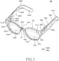
- FIG. 1 illustrates an electronic device 100 according to an embodiment of the disclosure.
- the electronic device 100 of FIG. 1 may include some or all of the components constituting an electronic device 901 of FIG. 9 .
- the electronic device 100 may include a frame 110 and a leg member 120.
- the leg member 120 may include a first leg member 120-R and a second leg member 120-L.
- the leg member 120 may be coupled to at least one side of the frame 110.
- the leg member 120 may be rotatably connected to the frame 110 through hinges 124-L and 124-R, respectively.
- the first leg member 120-R may be rotatably connected to the frame 110 through the first hinge 124-R, respectively.
- the second leg member 120-L may be rotatably connected to the frame 110 through the second hinge 124-L, respectively.
- the first leg member 120-R may include the first hinge 124-R, a first printed circuit board (PCB) 123-R, a first speaker 122-R, and/or a first battery 121-R.
- PCB printed circuit board
- the second leg member 120-L may include the second hinge 124-L, a second printed circuit board (PCB) 123-L, and a second speaker 122-L, and/or a second battery 121-L.
- PCB printed circuit board
- the frame 110 may include a first optical member 111-R, a first camera 112-R, a first display 115-R, a first microphone 114-R, and a first light output module 125-R, a first optical module 116-R, a third optical module 117, a second optical member 111-L, a second camera 112-L, a second display 115-L, a second microphone 114-L, a third microphone 114-C (center), a second light output module 125-L, and a second optical module 116-L.
- the electronic device 100 may output an image signal by the light output module 125 through the first display 115-R and the second display 115-L.
- R and “L” positioned at the end of reference numerals in FIG. 1 may mean constructions positioned on the right and left when the electronic device 100 is worn.
- the construction positioned on the right when the electronic device 100 is worn may be driven by power output from the first battery 121-R.
- the construction positioned on the left when the electronic device 100 is worn may be driven by power output from the second battery 121-L.
- the electronic device 100 may include only any one of the first battery 121-R and the second battery 121-L.
- the constructions e.g., the first printed circuit board 123-R, the second printed circuit board 123-L, the first speaker 122-R, the second speaker 122-L, the first battery 121-R, and the second battery 121-L
- the constructions positioned in the first leg part 120-R and/or the second leg part 120-L are shown to be exposed to the outside, but this is only for convenience of description, and the constructions may not be exposed to the outside because they are positioned inside the first leg part 120-R and/or the second leg part 120-L.
- the first light output module 125-R and the second light output module 125-L may be referred to as the light output module 125.
- the first printed circuit board 123-R and the second printed circuit board 123-L may be referred to as a printed circuit board 123.
- the first speaker 122-R and the second speaker 122-L may be referred to as a speaker 122.
- the first optical member 111-R and the second optical member 111-L may be referred to as an optical member 111.
- the first display 115-R and the second display 115-L may be referred to as a display 115.
- the first camera 112-R and the second camera 112-L may be referred to as a camera 112.
- the first optical module 116-R and the second optical module 116-L may be referred to as an optical module 116.
- the first optical module 116-R and the second optical module 116-L may be referred to as an optical module (or camera) 116 for eye tracking (ET).
- the third optical module 117 may be referred to as a photographing camera 117.
- the first camera 112-R and the second camera 112-L may recognize a movement of the user's body (e.g., head or hands) and a space according to 3 degrees of freedom (3DoF) or 6 degrees of freedom (6DoF).
- the first camera 112-R and the second camera 112-L may include a global shutter camera.
- the first camera 112-R and the second camera 112-L may perform spatial recognition for 6DoF and simultaneous localization and mapping (SLAM) functions for depth imaging.
- SLAM simultaneous localization and mapping
- the first optical module 116-R and the second optical module 116-L may detect and track the user's pupil.
- the center of a virtual image projected on the first display 115-R and the second display 115-L may be located according to a pupil movement of a user wearing the electronic device 100 tracked through the first optical module 116-R and the second optical module 116-L.
- the third camera 117 may include a high resolution (HR) or photo video (PV) camera. In an example, the third camera 117 may perform an auto focus (AF) function and an optical image stabilizer (OIS) function. In an example, the third camera 117 may include a global shutter camera, a color camera, and/or a rolling shutter camera.
- HR high resolution
- PV photo video
- AF auto focus
- OIS optical image stabilizer
- the third camera 117 may include a global shutter camera, a color camera, and/or a rolling shutter camera.
- the display member 113 may include the optical member 111 and the display 115.
- the electronic device 100 may be a wearable electronic device.
- the electronic device 100 may be a wearable electronic device of a glasses form (e.g., augmented reality (AR) glasses, smart glasses, or head mounted device).
- AR augmented reality
- smart glasses smart glasses
- head mounted device e.g., augmented reality (AR) glasses, smart glasses, or head mounted device.
- this is only exemplary, and the disclosure is not limited thereto.
- the first display member 113-R may be disposed to face the user's left eye
- the second display member 113-L may be disposed to face the user's right eye.
- the electronic device 100 may acquire an image of the real world through the camera 116, and receive an augmented reality (AR) object related to a location of the acquired image or an object (e.g., a thing or a building) included in the acquired image from another electronic device (e.g., a smart phone, a computer, a tablet personal computer (PC), or a server) and provide to a user through the light output module 125, the optical member 111, and the display 115.
- AR augmented reality
- the camera 112 and the optical module 116 may be used to recognize a current scene or environment which is viewed through the display member 113 of the electronic device 100.
- the electronic device 100 may receive an audio signal through the microphones 114-R, 114-L, and 114-C, and may output an audio signal through the speaker 122.
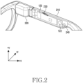
- FIG. 2 illustrates one region of the leg member 120 of the electronic device 100 according to an embodiment of the disclosure.
- the leg member 120 may be used as a term referring to the first leg member 120-R or the second leg member 120-L of FIG. 1 . Accordingly, the technical features of the leg member 120 to be described later may be applied to the first leg member 120-R and/or the second leg member 120-L.
- the leg member 120 may include a first structure 210 and a second structure 220.
- the first structure 210 and the second structure 220 may be a cover (or housing) of the leg member 120.
- the first structure 210 when the leg member 120 of the electronic device 100 is mounted on the user's body, the first structure 210 may be disposed in a first direction (e.g., a +z direction of FIG. 2 ) corresponding to an outward direction.
- the second structure 220 when the leg member 120 of the electronic device 100 is mounted on the user's body, the second structure 220 may be disposed in a second direction (e.g., a -z direction of FIG. 2 ) corresponding to an inward direction adjacent to the user's body.
- first structure 210 and the second structure 220 may be coupled to each other.
- first structure 210 and the second structure 220 are illustrated as separable separate structures, but are not limited thereto.
- first structure 210 and the second structure 220 may be integrally formed.
- first structure 210 and the second structure 220 may be a structure in which the leg member 120 is divided into a shape different from that shown in FIG. 2 and coupled.
- various electronic components may be disposed in a space formed between the first structure 210 and the second structure 220 by the coupling of the first structure 210 and the second structure 220.
- the speaker 122 and the printed circuit board 123 may be disposed in the space formed between the first structure 210 and the second structure 220. Referring to FIG. 2 , the speaker 122 and the printed circuit board 123 disposed in the space formed between the first structure 210 and the second structure 220 are shown to be visible, but this is for convenience of description, and the second structure 220 may be formed of an opaque material.
- the second structure 220 may include a ventilation hole 230 communicating with an internal space and external space formed by the coupling of the first structure 210 and the second structure 220.
- a heat provided from various electronic components disposed between the first structure 210 and the second structure 220 may be emitted through the ventilation hole 230 disposed in the second structure 220.
- the ventilation hole 230 is disposed at an upper side of the second structure 220 (e.g., a +y direction of FIG. 2 ), but is not limited thereto.
- the ventilation hole 230 may be disposed on a side surface of the second structure 220 (e.g., the second direction (e.g., the -z direction of FIG. 2 )).
- the second structure 220 may include a sound radiation hole 240.
- the sound radiation hole 240 may be disposed in a region adjacent to a space in which the speaker 122 is disposed. A sound output from a front surface of the speaker 122 (e.g., the +z direction of FIG. 2 ) may be output to the outside through the sound radiation hole 240.
- a resonance space e.g., a resonance space (RS2) of FIG. 5
- a rear surface e.g., the -z direction of FIG. 2
- a space in which the printed circuit board 123 is disposed may be formed in the second direction (e.g., the -z direction of FIG. 2 ) corresponding to the inward direction adjacent to the user's body.
- FIG. 3 illustrates a structure forming the leg member 120 of the electronic device 100 according to an embodiment of the disclosure.
- the second structure 220 may include the ventilation hole 230, the sound radiation hole 240, and a rib 250.
- the ventilation hole 230, the sound radiation hole 240 and the rib 250 are illustrated as being disposed in the second structure 220, but the ventilation hole 230, the sound radiation hole 240 and the rib 250 may be disposed in the first structure 210 and/or the second structure 220.
- the second structure 220 may include the rib 250 for mounting a printed circuit board (e.g., the printed circuit board 123 of FIG. 2 ) and a speaker (e.g., the speaker 122 of FIG. 2 ).
- the rib 250 may correspond to a protrusion which is formed to form an internal space of the leg member 120 by coupling the first structure 210 and the second structure 220.
- the rib 250 is illustrated as a protrusion having an entire rectangular shape, but is not limited thereto.
- the rib 250 may include a protrusion having various shapes.
- the rib 250 may be replaced with a recess for accommodating a component mounted in the internal space of the leg member 120.
- the rib 250 of the second structure 220 may be formed in the second direction (e.g., the -z direction of FIG. 3 ) corresponding to the inward direction in which the user's body is positioned when a user wears the electronic device 100 by means of the leg member 120.
- the second structure 220 may include the sound radiation hole 240.
- a sound provided from the speaker 122 may be radiated to the outside through the sound radiation hole 240.
- the sound radiation hole 240 may be disposed at a lower left side of the second structure 220.
- a speaker e.g., the speaker 122 of FIG. 2
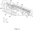
- FIG. 4 illustrates one region of the leg member 120 of the electronic device 100 according to an embodiment of the disclosure.
- the printed circuit board 123 and the speaker 122 may be disposed in an internal space formed through the first structure 210 and the second structure 220 of the leg member 120.
- an antenna module e.g., an antenna module 997 of FIG. 9
- a memory e.g., a memory 930 of FIG. 9
- a processor e.g., a processor 920 of FIG. 9
- a power management module e.g., a power management module 988 of FIG. 9
- the components disposed on the printed circuit board 123 are not limited thereto.
- a waterproof member may be disposed in a region surrounding the inside of the ventilation hole 230 in order to prevent moisture from being introduced into the ventilation hole 230.
- the waterproof member may include at least one of a waterproof tape, a waterproof membrane, or a waterproof member (e.g., porous material, Gore-Tex).
- the printed circuit board 123 and the speaker 122 may be accommodated by the rib 250 formed in the second structure 220.
- the internal space formed by the coupling of the first structure 210 and the second structure 220 may be connected to the rear surface (e.g., the -z direction of FIG. 4 ) of the speaker 122, and may include a resonance space (e.g., a resonance space (RS2) of FIG. 5 ) including a region in which the printed circuit board 123 is disposed. Accordingly, a sound output from the speaker 122 may be expanded through the resonance space connected to the rear surface of the speaker 122.
- a resonance space e.g., a resonance space (RS2) of FIG. 5
- the ventilation hole 230 may be disposed in at least one region of the rib 250 disposed in the second structure 220, to be connected to the resonance space (RS2) included in the internal space formed by the coupling of the first structure 210 and the second structure 220.
- RS2 resonance space
- a sealing member 260 may be disposed in a region in which the rib 250 and the speaker 122 contact with each other and in a region in which the rib 250 and the printed circuit board 123 contact with each other.
- the sealing member 260 may be disposed in the region where the rib 250 and the speaker 122 contact with each other and the region where the rib 250 and the printed circuit board 123 contact with each other, thereby preventing a sound leakage from the rear surface of the speaker 122 and ensuring the performance of a back volume output to the rear surface of the speaker 122 through the resonance space (RS2).
- RS2 resonance space
- the sealing member 260 may include Poron.
- the disclosure is not limited thereto.
- the sealing member 260 may include at least one of a sponge, a tape, a rubber, a silicone rubber, and urethane.
- the sealing member 260 may be formed in a closed curve that is formed along a circumference of the rib 250 for accommodating the speaker 122 and the printed circuit board 123.
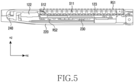
- FIG. 5 is a cross-sectional view taken along line A-A' of the leg member 120 of FIG. 4 according to an embodiment of the disclosure.
- the internal space formed by the coupling of the first structure 210 and the second structure 220 may include a radiating space (RS 1) and a resonance space (RS2).
- RS 1 radiating space
- RS2 resonance space
- the speaker 122 may include a front surface and a rear surface.
- the front surface (e.g., a +z direction of FIG. 5 ) of the speaker 122 may be one surface through which a sound output from the speaker 122 is directly radiated and connected to the sound radiation hole 240.
- the rear surface (e.g., a -z direction of FIG. 5 ) of the speaker 122 may be one surface facing the front surface of the speaker 122.
- the speaker 122 may be disposed in a seating region of the speaker 122 wherein the front surface of the speaker 122 faces the rear surface of the speaker 122.
- the front surface of the speaker 122 may be connected to the sound radiation hole 240 and output a sound in a first direction (e.g., the +z direction of FIG. 5 ).
- the rear surface of the speaker 122 may be connected to the resonance space (RS2) for providing a resonance with respect to a sound radiated in a second direction (the -z direction of FIG. 5 ).
- the front surface of the speaker 122 may be connected to a space connected to the sound radiation hole 240 distinguished from the radiating space (RS 1).
- the rear surface of the speaker 122 may be connected to the resonance space (RS2) including a region in which the printed circuit board 123 is disposed.
- the printed circuit board 123 may include one surface facing the second direction and the other surface facing the first direction.
- a first electronic component (not shown) may be disposed on the other surface of the printed circuit board 123.
- a second electronic component (not shown) may be disposed on one surface of the printed circuit board 123.
- the other surface of the printed circuit board 123 may be connected to the radiating space (RS 1).
- the radiating space (RS 1) may include a heat radiating member (e.g., a first heat radiating member 511 and/or a second heat radiating member 512).
- the second heat radiating member 512 may be disposed at a position where the printed circuit board 123 is adjacent.
- the first heat radiating member 511 may be disposed in a first direction of the second heat radiating member 512.
- the first heat radiating member 511 and the second heat radiating member 512 may include a radiating plate, a heat pipe, a thermal interface material (TIM), or a graphite sheet.
- a heat emitted from the first electronic component disposed on the other surface of the printed circuit board 123 may be emitted (or diffused) to the outside through the heat radiating member (e.g., the first heat radiating member 511 and/or the second heat radiating member 512).
- a heat provided by the printed circuit board 123 may be more effectively radiated through the radiating space (RS 1) connected to the other surface of the printed circuit board 123 than the resonance space (RS2) connected to the one surface of the printed circuit board 123. Accordingly, the first electronic component having higher power consumption than the second electronic component disposed on the one surface of the printed circuit board 123 may be disposed on the other surface of the printed circuit board 123.
- the resonance space (RS2) may be connected to the rear surface of the speaker 122 and be connected to at least one ventilation hole 230 formed in at least one region of the rib 250.
- a hole of a predetermined size or more is essential for sound radiation. Accordingly, the speaker 122 may radiate a sound to the outside through the sound radiation hole 240 connected to the front surface of the speaker 122 and the ventilation hole 230 connected to the rear surface of the speaker 122.
- the ventilation hole 230 may function as a damping hole for the speaker 122.
- a heat provided from the second electronic component (not shown) disposed on the one surface (e.g., the -z direction of FIG. 5 ) of the printed circuit board 123 may be diffused into the resonance space (RS2) and be diffused to the outside through the ventilation hole 230 connected to the resonance space (RS2).
- the ventilation hole 230 may function as an air vent hole wherein a heat provided by the printed circuit board 123 may be discharged.
- a heat radiating member (not shown) may be disposed in a region adjacent to the resonance space (RS2).
- a graphite sheet may be attached as the heat radiating member to at least one region adjacent to the one surface of the printed circuit board 123 in the rib 250 of the second structure 220.
- FIG. 6 illustrates a heat radiating member 510 included in the leg member 120 of the electronic device 100 according to an embodiment of the disclosure.
- the heat radiating member 510 disposed in the radiating space (RS 1) of FIG. 5 may include a first heat radiating member 511, a second heat radiating member 512, and a third heat radiating member 513.
- the heat radiating member 510 may be disposed in the radiating space (RS 1) connected to the other surface of the printed circuit board 123.
- the third heat radiating member 513, the second heat radiating member 512, and the first heat radiating member 511 may be sequentially disposed in a first direction (e.g., a +z direction of FIG. 6 ).
- the first heat radiating member 511 may include a radiating plate.
- the first heat radiating member 511 may include an aluminum material.
- the first heat radiating member 511 may have a plurality of protrusions protruded in the first direction.
- the plurality of protrusions of the first heat radiating member 511 may guide a heat radiating direction.
- the second heat radiating member 512 may include a heat pipe.
- the third heat radiating member 513 may include a graphite sheet.
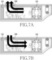
- FIGS. 7A and 7B illustrates a heat radiating path dependent on the provision of a sound pressure of the speaker 122 included in the leg member 120 of the electronic device 101 according to various embodiments of the disclosure.
- FIG. 7A shows that air is discharged from the resonance space (RS2) through the ventilation hole 230.
- the resonance space (RS2) corresponds to a positive sound pressure according to a sound provided by the speaker 122 and thus a pressure of the resonance space (RS2) is higher than that of an external space connected to the ventilation hole 230, air within the resonance space (RS2) may be emitted to the outside
- FIG. 7B illustrates that air is introduced into the resonance space (RS2) through the ventilation hole 230.
- the resonance space (RS2) corresponds to a negative sound pressure according to a sound provided by the speaker 122 and thus the pressure of the resonance space (RS2) is lower than that of the external space connected to the ventilation hole 230, air may be introduced into the resonance space (RS2).
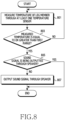
- FIG. 8 is a flowchart for controlling a speaker according to a temperature of an electronic device according to an embodiment of the disclosure.
- the electronic device 100 e.g., a processor 920 of FIG. 9
- the electronic device 100 may measure a temperature of the leg member 120 through at least one temperature sensor.
- the leg member 120 may include at least one temperature sensor.
- the at least one temperature sensor may be disposed in a position adjacent to the printed circuit board 123 and/or the speaker 122 included in the leg member 120.
- the electronic device 100 may sense a temperature of the leg member 120, through the at least one temperature sensor disposed in the position adjacent to the printed circuit board 123 and/or the speaker 122.
- the electronic device 100 may measure a temperature of a module disposed on the printed circuit board 123 and/or a temperature of an amplifier included in the speaker 122, through the at least one temperature sensor.
- the electronic device 100 e.g., the processor 920 of FIG. 9 ) of an embodiment may determine whether the temperature measured by the at least one temperature sensor is equal to or greater than a first temperature range.
- the electronic device 100 may control the speaker 122 in order to radiate a heat provided by various electronic components (e.g., the speaker 122 and/or the printed circuit board 123 of FIG. 1 ) disposed in the leg member 120.
- a first temperature e.g., about 40°C
- the electronic device 100 e.g., the processor 920 of FIG. 9 ) of an embodiment may, in operation 805, determine whether a sound signal is being output through the speaker 122.
- a sound pressure by a sound is formed in the resonance space (RS2) connected to the rear surface of the speaker 122 and thus, air within the resonance space (RS2) may be circulated through the ventilation hole 230.
- the electronic device 100 may control the speaker 122 to output the sound signal .
- the sound signal output through the speaker 122 through the control of the electronic device 100 may include an inaudible frequency signal (e.g., a frequency of about 20 Hz or less).
- FIG. 9 is a block diagram illustrating an electronic device 901 in a network environment 900 according to an embodiment of the disclosure.
- the electronic device 901 in the network environment 900 may communicate with an electronic device 902 via a first network 998 (e.g., a short-range wireless communication network), or at least one of an electronic device 904 or a server 908 via a second network 999 (e.g., a long-range wireless communication network).
- a first network 998 e.g., a short-range wireless communication network
- a second network 999 e.g., a long-range wireless communication network
- the electronic device 901 may communicate with the electronic device 904 via the server 908.
- the electronic device 901 may include a processor 920, memory 930, an input module 950, a sound output module 955, a display module 960, an audio module 970, a sensor module 976, an interface 977, a connecting terminal 978, a haptic module 979, a camera module 980, a power management module 988, a battery 989, a communication module 990, a subscriber identification module (SIM) 996, or an antenna module 997.
- at least one of the components e.g., the 99connecting terminal 978
- some of the components e.g., the sensor module 976, the camera module 980, or the antenna module 997) may be implemented as a single component (e.g., the display module 960).
- the processor 920 may execute, for example, software (e.g., a program 940) to control at least one other component (e.g., a hardware or software component) of the electronic device 901 coupled with the processor 920, and may perform various data processing or computation. According to one embodiment, as at least part of the data processing or computation, the processor 920 may store a command or data received from another component (e.g., the sensor module 976 or the communication module 990) in volatile memory 932, process the command or the data stored in the volatile memory 932, and store resulting data in non-volatile memory 934.
- software e.g., a program 940
- the processor 920 may store a command or data received from another component (e.g., the sensor module 976 or the communication module 990) in volatile memory 932, process the command or the data stored in the volatile memory 932, and store resulting data in non-volatile memory 934.
- the processor 920 may include a main processor 921 (e.g., a central processing unit (CPU) or an application processor (AP)), or an auxiliary processor 923 (e.g., a graphics processing unit (GPU), a neural processing unit (NPU), an image signal processor (ISP), a sensor hub processor, or a communication processor (CP)) that is operable independently from, or in conjunction with, the main processor 921.
- a main processor 921 e.g., a central processing unit (CPU) or an application processor (AP)
- auxiliary processor 923 e.g., a graphics processing unit (GPU), a neural processing unit (NPU), an image signal processor (ISP), a sensor hub processor, or a communication processor (CP)
- the main processor 921 may be adapted to consume less power than the main processor 921, or to be specific to a specified function.
- the auxiliary processor 923 may be implemented as separate from, or as part of the main processor 921.
- the auxiliary processor 923 may control at least some of functions or states related to at least one component (e.g., the display module 960, the sensor module 976, or the communication module 990) among the components of the electronic device 901, instead of the main processor 921 while the main processor 921 is in an inactive (e.g., sleep) state, or together with the main processor 921 while the main processor 921 is in an active state (e.g., executing an application).
- the auxiliary processor 923 e.g., an image signal processor or a communication processor
- the auxiliary processor 923 may include a hardware structure specified for artificial intelligence model processing.
- An artificial intelligence model may be generated by machine learning. Such learning may be performed, e.g., by the electronic device 901 where the artificial intelligence is performed or via a separate server (e.g., the server 908). Learning algorithms may include, but are not limited to, e.g., supervised learning, unsupervised learning, semi-supervised learning, or reinforcement learning.
- the artificial intelligence model may include a plurality of artificial neural network layers.
- the artificial neural network may be a deep neural network (DNN), a convolutional neural network (CNN), a recurrent neural network (RNN), a restricted boltzmann machine (RBM), a deep belief network (DBN), a bidirectional recurrent deep neural network (BRDNN), deep Q-network or a combination of two or more thereof but is not limited thereto.
- the artificial intelligence model may, additionally or alternatively, include a software structure other than the hardware structure.
- the memory 930 may store various data used by at least one component (e.g., the processor 920 or the sensor module 976) of the electronic device 901.
- the various data may include, for example, software (e.g., the program 940) and input data or output data for a command related thereto.
- the memory 930 may include the volatile memory 932 or the non-volatile memory 934.
- the program 940 may be stored in the memory 930 as software, and may include, for example, an operating system (OS) 942, middleware 944, or an application 946.
- OS operating system
- middleware middleware
- application application
- the input module 950 may receive a command or data to be used by another component (e.g., the processor 920) of the electronic device 901, from the outside (e.g., a user) of the electronic device 901.
- the input module 950 may include, for example, a microphone, a mouse, a keyboard, a key (e.g., a button), or a digital pen (e.g., a stylus pen).
- the sound output module 955 may output sound signals to the outside of the electronic device 901.
- the sound output module 955 may include, for example, a speaker or a receiver.
- the speaker may be used for general purposes, such as playing multimedia or playing record.
- the receiver may be used for receiving incoming calls. According to an embodiment, the receiver may be implemented as separate from, or as part of the speaker.
- the display module 960 may visually provide information to the outside (e.g., a user) of the electronic device 901.
- the display module 960 may include, for example, a display, a hologram device, or a projector and control circuitry to control a corresponding one of the display, hologram device, and projector.
- the display module 960 may include a touch sensor adapted to detect a touch, or a pressure sensor adapted to measure the intensity of force incurred by the touch.
- the audio module 970 may convert a sound into an electrical signal and vice versa. According to an embodiment, the audio module 970 may obtain the sound via the input module 950, or output the sound via the sound output module 955 or a headphone of an external electronic device (e.g., an electronic device 902) directly (e.g., wiredly) or wirelessly coupled with the electronic device 901.
- an external electronic device e.g., an electronic device 902
- directly e.g., wiredly
- wirelessly e.g., wirelessly
- the sensor module 976 may detect an operational state (e.g., power or temperature) of the electronic device 901 or an environmental state (e.g., a state of a user) external to the electronic device 901, and then generate an electrical signal or data value corresponding to the detected state.
- the sensor module 976 may include, for example, a gesture sensor, a gyro sensor, an atmospheric pressure sensor, a magnetic sensor, an acceleration sensor, a grip sensor, a proximity sensor, a color sensor, an infrared (IR) sensor, a biometric sensor, a temperature sensor, a humidity sensor, or an illuminance sensor.
- the interface 977 may support one or more specified protocols to be used for the electronic device 901 to be coupled with the external electronic device (e.g., the electronic device 902) directly (e.g., wiredly) or wirelessly.
- the interface 977 may include, for example, a high definition multimedia interface (HDMI), a universal serial bus (USB) interface, a secure digital (SD) card interface, or an audio interface.
- HDMI high definition multimedia interface
- USB universal serial bus
- SD secure digital
- a connecting terminal 978 may include a connector via which the electronic device 901 may be physically connected with the external electronic device (e.g., the electronic device 902).
- the connecting terminal 978 may include, for example, an HDMI connector, a USB connector, an SD card connector, or an audio connector (e.g., a headphone connector).
- the haptic module 979 may convert an electrical signal into a mechanical stimulus (e.g., a vibration or a movement) or electrical stimulus which may be recognized by a user via his tactile sensation or kinesthetic sensation.
- the haptic module 979 may include, for example, a motor, a piezoelectric element, or an electric stimulator.
- the camera module 980 may capture a still image or moving images.
- the camera module 980 may include one or more lenses, image sensors, image signal processors, or flashes.
- the power management module 988 may manage power supplied to the electronic device 901. According to one embodiment, the power management module 988 may be implemented as at least part of, for example, a power management integrated circuit (PMIC).
- PMIC power management integrated circuit
- the battery 989 may supply power to at least one component of the electronic device 901.
- the battery 989 may include, for example, a primary cell which is not rechargeable, a secondary cell which is rechargeable, or a fuel cell.
- the communication module 990 may support establishing a direct (e.g., wired) communication channel or a wireless communication channel between the electronic device 901 and the external electronic device (e.g., the electronic device 902, the electronic device 904, or the server 908) and performing communication via the established communication channel.
- the communication module 990 may include one or more communication processors that are operable independently from the processor 920 (e.g., the application processor (AP)) and supports a direct (e.g., wired) communication or a wireless communication.
- AP application processor
- the communication module 990 may include a wireless communication module 992 (e.g., a cellular communication module, a short-range wireless communication module, or a global navigation satellite system (GNSS) communication module) or a wired communication module 994 (e.g., a local area network (LAN) communication module or a power line communication (PLC) module).
- a wireless communication module 992 e.g., a cellular communication module, a short-range wireless communication module, or a global navigation satellite system (GNSS) communication module
- GNSS global navigation satellite system
- wired communication module 994 e.g., a local area network (LAN) communication module or a power line communication (PLC) module.
- LAN local area network
- PLC power line communication
- a corresponding one of these communication modules may communicate with the external electronic device via the first network 998 (e.g., a short-range communication network, such as Bluetooth TM , Wi-Fi direct, or infrared data association (IrDA)) or the second network 999 (e.g., a long-range communication network, such as a legacy cellular network, a 5th generation (5G) network, a next-generation communication network, the Internet, or a computer network (e.g., LAN or wide area network (WAN))).
- first network 998 e.g., a short-range communication network, such as Bluetooth TM , Wi-Fi direct, or infrared data association (IrDA)
- the second network 999 e.g., a long-range communication network, such as a legacy cellular network, a 5th generation (5G) network, a next-generation communication network, the Internet, or a computer network (e.g., LAN or wide area network (WAN)).
- 5G 5th
- the wireless communication module 992 may identify and authenticate the electronic device 901 in a communication network, such as the first network 998 or the second network 999, using subscriber information (e.g., international mobile subscriber identity (IMSI)) stored in the subscriber identification module 996.
- subscriber information e.g., international mobile subscriber identity (IMSI)
- the wireless communication module 992 may support a 5G network, after a 4th generation (4G) network, and next-generation communication technology, e.g., new radio (NR) access technology.
- the NR access technology may support enhanced mobile broadband (eMBB), massive machine type communications (mMTC), or ultra-reliable and low-latency communications (URLLC).
- eMBB enhanced mobile broadband
- mMTC massive machine type communications
- URLLC ultra-reliable and low-latency communications
- the wireless communication module 992 may support a high-frequency band (e.g., the millimeter wave (mmWave) band) to achieve, e.g., a high data transmission rate.
- mmWave millimeter wave
- the wireless communication module 992 may support various technologies for securing performance on a high-frequency band, such as, e.g., beamforming, massive multiple-input and multiple-output (massive MIMO), full dimensional MIMO (FD-MIMO), array antenna, analog beam-forming, or large scale antenna.
- the wireless communication module 992 may support various requirements specified in the electronic device 901, an external electronic device (e.g., the electronic device 904), or a network system (e.g., the second network 999).
- the wireless communication module 992 may support a peak data rate (e.g., 20Gbps or more) for implementing eMBB, loss coverage (e.g., 164dB or less) for implementing mMTC, or U-plane latency (e.g., 0.5ms or less for each of downlink (DL) and uplink (UL), or a round trip of 1ms or less) for implementing URLLC.
- a peak data rate e.g., 20Gbps or more
- loss coverage e.g., 164dB or less
- U-plane latency e.g., 0.5ms or less for each of downlink (DL) and uplink (UL), or a round trip of 1ms or less
- the antenna module 997 may transmit or receive a signal or power to or from the outside (e.g., the external electronic device) of the electronic device 901.
- the antenna module 997 may include an antenna including a radiating element composed of a conductive material or a conductive pattern formed in or on a substrate (e.g., a printed circuit board (PCB)).
- the antenna module 997 may include a plurality of antennas (e.g., array antennas). In such a case, at least one antenna appropriate for a communication scheme used in the communication network, such as the first network 998 or the second network 999, may be selected, for example, by the communication module 990 (e.g., the wireless communication module 992) from the plurality of antennas.
- the signal or the power may then be transmitted or received between the communication module 990 and the external electronic device via the selected at least one antenna.
- another component e.g., a radio frequency integrated circuit (RFIC)
- RFIC radio frequency integrated circuit
- the antenna module 997 may form a mmWave antenna module.
- the mmWave antenna module may include a printed circuit board, a RFIC disposed on a first surface (e.g., the bottom surface) of the printed circuit board, or adjacent to the first surface and capable of supporting a designated high-frequency band (e.g., the mmWave band), and a plurality of antennas (e.g., array antennas) disposed on a second surface (e.g., the top or a side surface) of the printed circuit board, or adjacent to the second surface and capable of transmitting or receiving signals of the designated high-frequency band.
- a RFIC disposed on a first surface (e.g., the bottom surface) of the printed circuit board, or adjacent to the first surface and capable of supporting a designated high-frequency band (e.g., the mmWave band)
- a plurality of antennas e.g., array antennas
- At least some of the above-described components may be coupled mutually and communicate signals (e.g., commands or data) therebetween via an inter-peripheral communication scheme (e.g., a bus, general purpose input and output (GPIO), serial peripheral interface (SPI), or mobile industry processor interface (MIPI)).
- an inter-peripheral communication scheme e.g., a bus, general purpose input and output (GPIO), serial peripheral interface (SPI), or mobile industry processor interface (MIPI)
- commands or data may be transmitted or received between the electronic device 901 and the external electronic device 904 via the server 908 coupled with the second network 999.
- Each of the electronic devices 902 or 904 may be a device of a same type as, or a different type, from the electronic device 901.
- all or some of operations to be executed at the electronic device 901 may be executed at one or more of the external electronic devices 902, 904, or 908.
- the electronic device 901 instead of, or in addition to, executing the function or the service, may request the one or more external electronic devices to perform at least part of the function or the service.
- the one or more external electronic devices receiving the request may perform the at least part of the function or the service requested, or an additional function or an additional service related to the request, and transfer an outcome of the performing to the electronic device 901.
- the electronic device 901 may provide the outcome, with or without further processing of the outcome, as at least part of a reply to the request.
- a cloud computing, distributed computing, mobile edge computing (MEC), or client-server computing technology may be used, for example.
- the electronic device 901 may provide ultra low-latency services using, e.g., distributed computing or mobile edge computing.
- the external electronic device 904 may include an internet-of things (IoT) device.
- the server 908 may be an intelligent server using machine learning and/or a neural network.
- the external electronic device 904 or the server 908 may be included in the second network 999.
- the electronic device 901 may be applied to intelligent services (e.g., smart home, smart city, smart car, or healthcare) based on 5G communication technology or IoT-related technology.
- the electronic device may be one of various types of electronic devices.
- the electronic devices may include, for example, a portable communication device (e.g., a smartphone), a computer device, a portable multimedia device, a portable medical device, a camera, a wearable device, or a home appliance. According to an embodiment of the disclosure, the electronic devices are not limited to those described above.
- each of such phrases as “A or B,” “at least one of A and B,” “at least one of A or B,” “A, B, or C,” “at least one of A, B, and C,” and “at least one of A, B, or C,” may include any one of, or all possible combinations of the items enumerated together in a corresponding one of the phrases.
- such terms as “1st” and “2nd,” or “first” and “second” may be used to simply distinguish a corresponding component from another, and does not limit the components in other aspect (e.g., importance or order).
- an element e.g., a first element
- the element may be coupled with the other element directly (e.g., wiredly), wirelessly, or via a third element.
- Various embodiments as set forth herein may be implemented as software (e.g., the program 940) including one or more instructions that are stored in a storage medium (e.g., internal memory 936 or external memory 938) that is readable by a machine (e.g., the electronic device 901).
- a processor e.g., the processor 920
- the machine e.g., the electronic device 901
- the one or more instructions may include a code generated by a complier or a code executable by an interpreter.
- the machine-readable storage medium may be provided in the form of a non-transitory storage medium.
- non-transitory simply means that the storage medium is a tangible device, and does not include a signal (e.g., an electromagnetic wave), but this term does not differentiate between where data is semi-permanently stored in the storage medium and where the data is temporarily stored in the storage medium.
- a method may be included and provided in a computer program product.
- the computer program product may be traded as a product between a seller and a buyer.
- the computer program product may be distributed in the form of a machine-readable storage medium (e.g., compact disc read only memory (CD-ROM)), or be distributed (e.g., downloaded or uploaded) online via an application store (e.g., PlayStore TM ), or between two user devices (e.g., smart phones) directly. If distributed online, at least part of the computer program product may be temporarily generated or at least temporarily stored in the machine-readable storage medium, such as memory of the manufacturer's server, a server of the application store, or a relay server.
- CD-ROM compact disc read only memory
- an application store e.g., PlayStore TM
- two user devices e.g., smart phones
- each component e.g., a module or a program of the above-described components may include a single entity or multiple entities, and some of the multiple entities may be separately disposed in different components. According to various embodiments, one or more of the above-described components may be omitted, or one or more other components may be added. Alternatively or additionally, a plurality of components (e.g., modules or programs) may be integrated into a single component. In such a case, according to various embodiments, the integrated component may still perform one or more functions of each of the plurality of components in the same or similar manner as they are performed by a corresponding one of the plurality of components before the integration.
- operations performed by the module, the program, or another component may be carried out sequentially, in parallel, repeatedly, or heuristically, or one or more of the operations may be executed in a different order or omitted, or one or more other operations may be added.
- An electronic device of various embodiments may include a display member including at least one glass, a frame supporting at least a portion of the display member, and a leg member coupled to at least one side of the frame.
- the leg member may include a first structure, a second structure possible to be coupled with the first structure, a speaker disposed in a space formed between the first structure and the second structure, a printed circuit board disposed in the space formed between the first structure and the second structure, and a rib included in at least one of the first structure or the second structure and accommodating the printed circuit board.
- a rear surface of the speaker may be disposed to face a resonance space formed between the first structure and the second structure, and the resonance space may include a space in which the printed circuit board is disposed, and may be connected to at least one ventilation hole formed in at least one region of the rib so as to be connected to the outside of the leg member.
- One surface of the printed circuit board of an embodiment may be disposed to face the resonance space, and the other surface of the printed circuit board may be disposed to face a radiating space separated from the resonance space.
- a first electronic component of an embodiment may be disposed on the other surface of the printed circuit board disposed to be connected to the radiating space, and a second electronic component consuming less power than the first electronic component may be disposed on the one surface of the circuit board disposed to be connected to the resonance space.
- At least one of a radiating plate, a heat pipe, a thermal interface material (TIM), and a graphite sheet of an embodiment may be disposed in the radiating space.
- the first structure or the second structure of an embodiment may form a space connecting a sound radiation hole, which is formed in at least one of the first structure or second structure, and a front surface of the speaker.
- the electronic device of an embodiment may further include a waterproof member for preventing moisture from being introduced into the ventilation hole, in a region surrounding the inside of the ventilation hole.
- the waterproof member of an embodiment may include at least one of a waterproof mesh, a waterproof tape, a waterproof membrane, and a Gore-Tex member.
- the electronic device of an embodiment may further include a sealing member in at least one region of the rib for accommodating the speaker and the printed circuit board.
- the sealing member of an embodiment may include Poron.
- the sealing member of an embodiment may be configured in a closed curve shape along a circumference of the rib accommodating the speaker and the printed circuit board.
- the at least one ventilation hole of an embodiment may be disposed in at least one region of an upper portion or a lower portion of the rib.
- the electronic device of an embodiment may further include at least one temperature sensor disposed in the space formed between the first structure and the second structure, and at least one processor electrically connected to the speaker, the printed circuit board, or the at least one temperature sensor.
- the at least one processor may measure a temperature of the leg member through the at least one temperature sensor, determine whether the measured temperature is equal to or greater than a first temperature, and when the measured temperature is equal to or greater than the first temperature, determine whether a sound signal is being output through the speaker, and when the sound signal is not being output through the speaker, output the sound signal through the speaker.
- the at least one processor of an embodiment may adjust a volume intensity of the speaker and output an inaudible frequency signal.
- the inaudible frequency signal of an embodiment may include a frequency domain of about 20 Hz or less.
- the electronic device of an embodiment may further include an amplifier electrically connected to the speaker.
- An electronic device of various embodiments may include a display member including at least one glass, a frame supporting at least a portion of the display member, and a leg member coupled to at least one side of the frame.
- the leg member may include a housing, a speaker disposed in a space formed inside the housing, a printed circuit board disposed in the space formed inside the housing, and a rib for accommodating the printed circuit board in at least one region of the housing.
- a rear surface of the speaker may be disposed to face a resonance space formed inside the housing, and the resonance space may include a space in which the printed circuit board is disposed, and may be connected to at least one ventilation hole formed in at least one region of the rib so as to be connected to the outside of the leg member.
- the housing of an embodiment may have a sound radiation hole formed in at least one region of the housing, and a space connected to the front surface of the speaker.
- the electronic device of an embodiment may further include a waterproof member in a region surrounding the inside of the at least one ventilation hole.
- the electronic device of an embodiment may further include at least one temperature sensor disposed in a space formed inside the housing, and at least one processor electrically connected to the speaker, the printed circuit board, or the at least one temperature sensor.
- the at least one processor may measure a temperature of the leg member through the at least one temperature sensor, determine whether the measured temperature is equal to or greater than a first temperature, and when the measured temperature is equal to or greater than the first temperature, determine whether a sound signal is being output through the speaker, and when the sound signal is not being output through the speaker, output the sound signal through the speaker.
- the at least one processor of an embodiment may adjust a volume intensity of the speaker and output an inaudible frequency signal.
Landscapes
- Physics & Mathematics (AREA)
- Engineering & Computer Science (AREA)
- Microelectronics & Electronic Packaging (AREA)
- General Physics & Mathematics (AREA)
- Optics & Photonics (AREA)
- Health & Medical Sciences (AREA)
- Thermal Sciences (AREA)
- Otolaryngology (AREA)
- Acoustics & Sound (AREA)
- Ophthalmology & Optometry (AREA)
- Signal Processing (AREA)
- Nonlinear Science (AREA)
- General Health & Medical Sciences (AREA)
- Crystallography & Structural Chemistry (AREA)
- Chemical & Material Sciences (AREA)
- Mathematical Physics (AREA)
- Details Of Audible-Bandwidth Transducers (AREA)
- Telephone Set Structure (AREA)
- Cooling Or The Like Of Electrical Apparatus (AREA)
Applications Claiming Priority (2)
| Application Number | Priority Date | Filing Date | Title |
|---|---|---|---|
| KR1020210075008A KR102946233B1 (ko) | 2021-06-09 | 2021-06-09 | 방열 구조를 포함하는 전자 장치 |
| PCT/KR2022/007490 WO2022260319A1 (ko) | 2021-06-09 | 2022-05-26 | 방열 구조를 포함하는 전자 장치 |
Publications (3)
| Publication Number | Publication Date |
|---|---|
| EP4274397A1 true EP4274397A1 (de) | 2023-11-08 |
| EP4274397A4 EP4274397A4 (de) | 2024-08-28 |
| EP4274397B1 EP4274397B1 (de) | 2025-07-02 |
Family
ID=84426131
Family Applications (1)
| Application Number | Title | Priority Date | Filing Date |
|---|---|---|---|
| EP22820447.5A Active EP4274397B1 (de) | 2021-06-09 | 2022-05-26 | Elektronische vorrichtung mit wärmeableitungsstruktur |
Country Status (4)
| Country | Link |
|---|---|
| US (1) | US20230025734A1 (de) |
| EP (1) | EP4274397B1 (de) |
| KR (1) | KR102946233B1 (de) |
| WO (1) | WO2022260319A1 (de) |
Families Citing this family (3)
| Publication number | Priority date | Publication date | Assignee | Title |
|---|---|---|---|---|
| WO2025107110A1 (en) * | 2023-11-20 | 2025-05-30 | Harman International Industries , Incorporated | Audio glasses device |
| WO2025138075A1 (en) * | 2023-12-29 | 2025-07-03 | Harman International Industries , Incorporated | Audio glasses device |
| WO2026049209A1 (ko) * | 2024-08-26 | 2026-03-05 | 삼성전자주식회사 | 방열 시트들을 포함하는 웨어러블 장치 |
Family Cites Families (40)
| Publication number | Priority date | Publication date | Assignee | Title |
|---|---|---|---|---|
| JP4333778B2 (ja) * | 2007-05-23 | 2009-09-16 | 船井電機株式会社 | スピーカを内蔵した機器、液晶テレビジョン受像機 |
| CN108873372B (zh) * | 2018-08-24 | 2024-06-14 | 深圳市韶音科技有限公司 | 一种铰链及眼镜 |
| WO2014163797A1 (en) * | 2013-03-13 | 2014-10-09 | Kopin Corporation | Noise cancelling microphone apparatus |
| TWI549649B (zh) * | 2013-09-24 | 2016-09-21 | 廣達電腦股份有限公司 | 頭戴式系統 |
| US20160252727A1 (en) * | 2015-02-27 | 2016-09-01 | LAFORGE Optical, Inc. | Augmented reality eyewear |
| CN204598287U (zh) * | 2015-05-26 | 2015-08-26 | 北京亮亮视野科技有限公司 | 一种微型音箱 |
| FR3036918B1 (fr) * | 2015-05-29 | 2018-08-10 | Thales | Carte electronique et procede de fabrication associe |
| US10379376B2 (en) * | 2015-10-20 | 2019-08-13 | Kopin Corporation | Wearable electronic display |
| DE102016103477A1 (de) * | 2016-02-26 | 2017-08-31 | USound GmbH | Audiosystem mit strahlformenden Lautsprechern sowie Brille mit einem derartigen Audiosystem |
| KR101786613B1 (ko) * | 2016-05-16 | 2017-10-18 | 주식회사 정글 | 스피커가 장착된 안경 |
| WO2018039277A1 (en) * | 2016-08-22 | 2018-03-01 | Magic Leap, Inc. | Diffractive eyepiece |
| KR101819530B1 (ko) * | 2016-11-02 | 2018-01-17 | 주식회사 정글 | 골전도 스피커가 장착된 안경 다리 |
| WO2018110161A1 (ja) * | 2016-12-16 | 2018-06-21 | ソニー株式会社 | ウエアラブルスピーカ及び再生装置 |
| CN107065228A (zh) * | 2017-06-27 | 2017-08-18 | 丹阳市精通眼镜技术创新服务中心有限公司 | 一种儿童冷热监护智能提醒眼镜及其制作方法 |
| WO2019126175A1 (en) * | 2017-12-20 | 2019-06-27 | Vuzix Corporation | Augmented reality display system |
| KR20190082034A (ko) * | 2017-12-29 | 2019-07-09 | 주식회사 정글 | 웨어러블 디바이스 |
| US10904667B1 (en) * | 2018-03-19 | 2021-01-26 | Amazon Technologies, Inc. | Compact audio module for head-mounted wearable device |
| US10353221B1 (en) * | 2018-07-31 | 2019-07-16 | Bose Corporation | Audio eyeglasses with cable-through hinge and related flexible printed circuit |
| WO2020038475A1 (zh) * | 2018-08-24 | 2020-02-27 | 深圳市韶音科技有限公司 | 一种扬声器 |
| CN109143587A (zh) * | 2018-10-19 | 2019-01-04 | 歌尔科技有限公司 | Ar智能眼镜 |
| CN110031976A (zh) * | 2019-02-15 | 2019-07-19 | 山西见声科技有限公司 | 一种具有报警功能的眼镜及其控制方法 |
| CN109862496A (zh) * | 2019-04-12 | 2019-06-07 | 深圳市广扬科技有限公司 | 一种近耳的定向出音结构及其音频眼镜 |
| KR102734308B1 (ko) * | 2019-05-31 | 2024-11-27 | 삼성전자주식회사 | 방열 부재를 포함하는 전자 장치 |
| US11375302B2 (en) * | 2019-07-22 | 2022-06-28 | AAC Technologies Pte. Ltd. | Speaker device and mobile terminal provided with speaker device |
| US11375301B2 (en) * | 2019-07-22 | 2022-06-28 | AAC Technologies Pte. Ltd. | Speaker box device and mobile terminal using same |
| KR102651418B1 (ko) * | 2019-07-25 | 2024-03-27 | 삼성전자 주식회사 | 차폐 시트 및 방열 부재를 포함하는 전자 장치 |
| US11166099B2 (en) * | 2019-09-27 | 2021-11-02 | Apple Inc. | Headphone acoustic noise cancellation and speaker protection or dynamic user experience processing |
| CN110856055A (zh) * | 2019-10-15 | 2020-02-28 | 瑞声科技(新加坡)有限公司 | 扬声器装置及移动终端 |
| KR102107049B1 (ko) * | 2019-11-21 | 2020-05-07 | 에스텍 주식회사 | 템플 조립체 및 이를 포함하는 안경 |
| KR102157575B1 (ko) * | 2020-03-04 | 2020-09-18 | 에스텍 주식회사 | 음향 지향성을 집중시킨 템플 조립체 및 이를 포함하는 안경 |
| CN212009160U (zh) * | 2020-05-19 | 2020-11-24 | 深圳市安吉恩科技有限公司 | 一种基于wifi、4g、5g技术的智能眼镜 |
| CN113946061B (zh) * | 2020-07-17 | 2022-12-27 | 华为技术有限公司 | 眼镜及可穿戴系统 |
| CN112099231A (zh) * | 2020-09-08 | 2020-12-18 | 重庆爱奇艺智能科技有限公司 | 一种眼镜式头戴设备 |
| TWM606182U (zh) * | 2020-09-17 | 2021-01-01 | 鄭溪州 | 帶有藍芽無線雙聲道耳機的多功能眼鏡 |
| CN112083585A (zh) * | 2020-10-21 | 2020-12-15 | 深圳市深科创投科技有限公司 | 一种镜腿的发声体安装结构和音频眼镜 |
| CN112505923B (zh) * | 2020-11-13 | 2023-03-21 | Oppo广东移动通信有限公司 | 主板及头戴式设备 |
| CN112255803A (zh) * | 2020-11-13 | 2021-01-22 | Oppo广东移动通信有限公司 | 镜腿及眼镜 |
| CN112363325A (zh) * | 2020-12-02 | 2021-02-12 | 深圳联合在线科技有限公司 | 一种智能音乐眼镜 |
| CN113189778B (zh) * | 2021-04-27 | 2023-12-01 | 歌尔股份有限公司 | 镜腿结构、及其制备方法和头戴式显示设备 |
| CN113960807A (zh) * | 2021-11-04 | 2022-01-21 | 惠州Tcl移动通信有限公司 | 一种智能眼镜及其镜腿组件 |
-
2021
- 2021-06-09 KR KR1020210075008A patent/KR102946233B1/ko active Active
-
2022
- 2022-05-26 EP EP22820447.5A patent/EP4274397B1/de active Active
- 2022-05-26 WO PCT/KR2022/007490 patent/WO2022260319A1/ko not_active Ceased
- 2022-10-05 US US17/960,404 patent/US20230025734A1/en active Pending
Also Published As
| Publication number | Publication date |
|---|---|
| KR20220166107A (ko) | 2022-12-16 |
| WO2022260319A1 (ko) | 2022-12-15 |
| EP4274397B1 (de) | 2025-07-02 |
| KR102946233B1 (ko) | 2026-03-31 |
| US20230025734A1 (en) | 2023-01-26 |
| EP4274397A4 (de) | 2024-08-28 |
Similar Documents
| Publication | Publication Date | Title |
|---|---|---|
| US20230025734A1 (en) | Electronic device including heat radiating structure | |
| US12302049B2 (en) | Electronic device comprising microphone module | |
| EP4266655B1 (de) | Akustische komponente und elektronische vorrichtung damit | |
| US12276800B2 (en) | Wearable device for adjusting light transmittance according to illuminance of external light source, and method for controlling same | |
| US20250274645A1 (en) | Electronic device including camera module | |
| KR20240069549A (ko) | 카메라 모듈을 포함하는 웨어러블 전자 장치 | |
| US12375845B2 (en) | Audio output device including extended resonance space and electronic device including the same | |
| US12439189B2 (en) | Electronic device comprising microphone module | |
| EP4550961A1 (de) | Leiterplattenmodul und elektronische vorrichtung damit | |
| US12164341B2 (en) | Electronic device including air vent hole | |
| US20230188840A1 (en) | Electronic device for executing applications by using different pieces of camera information according to capturing environment and method for controlling same | |
| US12101585B2 (en) | Speaker module mounting structure and electronic device including the same | |
| US20220113766A1 (en) | Electronic device including flexible display and method for controlling temperature according to state of electronic device using the same | |
| US20250147395A1 (en) | Wearable electronic device comprising camera module | |
| US12292578B2 (en) | Electronic device including structure for adjusting distance between lenses | |
| EP4668720A1 (de) | Elektronische vorrichtung mit belüftungsstruktur | |
| US12574451B2 (en) | Camera assembly and electronic device including same | |
| EP4561109A1 (de) | Elektronische vorrichtung mit isolationsstruktur für lautsprecher | |
| US20250027830A1 (en) | Electronic device including sensor assembly | |
| US12481331B2 (en) | Electronic device including sound unit | |
| US20260003404A1 (en) | Electronic device including waterproofing structure | |
| US20250208655A1 (en) | Electronic apparatus comprising frame detachably coupled to housing | |
| US20250344321A1 (en) | Electronic device having structure for coupling module including electronic component to frame | |
| EP4572546A1 (de) | Elektronische vorrichtung mit wasserdichter struktur | |
| EP4572332A1 (de) | Elektronische vorrichtung mit lautsprechereinheit |
Legal Events
| Date | Code | Title | Description |
|---|---|---|---|
| STAA | Information on the status of an ep patent application or granted ep patent |
Free format text: STATUS: THE INTERNATIONAL PUBLICATION HAS BEEN MADE |
|
| PUAI | Public reference made under article 153(3) epc to a published international application that has entered the european phase |
Free format text: ORIGINAL CODE: 0009012 |
|
| STAA | Information on the status of an ep patent application or granted ep patent |
Free format text: STATUS: REQUEST FOR EXAMINATION WAS MADE |
|
| 17P | Request for examination filed |
Effective date: 20230804 |
|
| AK | Designated contracting states |
Kind code of ref document: A1 Designated state(s): AL AT BE BG CH CY CZ DE DK EE ES FI FR GB GR HR HU IE IS IT LI LT LU LV MC MK MT NL NO PL PT RO RS SE SI SK SM TR |
|
| A4 | Supplementary search report drawn up and despatched |
Effective date: 20240730 |
|
| RIC1 | Information provided on ipc code assigned before grant |
Ipc: G02C 11/00 20060101ALI20240724BHEP Ipc: G02C 11/06 20060101ALI20240724BHEP Ipc: G02C 5/14 20060101ALI20240724BHEP Ipc: G02B 27/01 20060101ALI20240724BHEP Ipc: H05K 5/06 20060101ALI20240724BHEP Ipc: H04R 1/28 20060101ALI20240724BHEP Ipc: H05K 7/20 20060101AFI20240724BHEP |
|
| DAV | Request for validation of the european patent (deleted) | ||
| DAX | Request for extension of the european patent (deleted) | ||
| GRAP | Despatch of communication of intention to grant a patent |
Free format text: ORIGINAL CODE: EPIDOSNIGR1 |
|
| STAA | Information on the status of an ep patent application or granted ep patent |
Free format text: STATUS: GRANT OF PATENT IS INTENDED |
|
| INTG | Intention to grant announced |
Effective date: 20250124 |
|
| GRAS | Grant fee paid |
Free format text: ORIGINAL CODE: EPIDOSNIGR3 |
|
| GRAA | (expected) grant |
Free format text: ORIGINAL CODE: 0009210 |
|
| STAA | Information on the status of an ep patent application or granted ep patent |
Free format text: STATUS: THE PATENT HAS BEEN GRANTED |
|
| AK | Designated contracting states |
Kind code of ref document: B1 Designated state(s): AL AT BE BG CH CY CZ DE DK EE ES FI FR GB GR HR HU IE IS IT LI LT LU LV MC MK MT NL NO PL PT RO RS SE SI SK SM TR |
|
| REG | Reference to a national code |
Ref country code: GB Ref legal event code: FG4D |
|
| REG | Reference to a national code |
Ref country code: CH Ref legal event code: EP |
|
| REG | Reference to a national code |
Ref country code: DE Ref legal event code: R096 Ref document number: 602022017072 Country of ref document: DE |
|
| REG | Reference to a national code |
Ref country code: IE Ref legal event code: FG4D |
|
| REG | Reference to a national code |
Ref country code: NL Ref legal event code: MP Effective date: 20250702 |
|
| PG25 | Lapsed in a contracting state [announced via postgrant information from national office to epo] |
Ref country code: PT Free format text: LAPSE BECAUSE OF FAILURE TO SUBMIT A TRANSLATION OF THE DESCRIPTION OR TO PAY THE FEE WITHIN THE PRESCRIBED TIME-LIMIT Effective date: 20251103 |
|
| PG25 | Lapsed in a contracting state [announced via postgrant information from national office to epo] |
Ref country code: NL Free format text: LAPSE BECAUSE OF FAILURE TO SUBMIT A TRANSLATION OF THE DESCRIPTION OR TO PAY THE FEE WITHIN THE PRESCRIBED TIME-LIMIT Effective date: 20250702 |
|
| REG | Reference to a national code |
Ref country code: AT Ref legal event code: MK05 Ref document number: 1810831 Country of ref document: AT Kind code of ref document: T Effective date: 20250702 |
|
| PG25 | Lapsed in a contracting state [announced via postgrant information from national office to epo] |
Ref country code: IS Free format text: LAPSE BECAUSE OF FAILURE TO SUBMIT A TRANSLATION OF THE DESCRIPTION OR TO PAY THE FEE WITHIN THE PRESCRIBED TIME-LIMIT Effective date: 20251102 |
|
| PG25 | Lapsed in a contracting state [announced via postgrant information from national office to epo] |
Ref country code: NO Free format text: LAPSE BECAUSE OF FAILURE TO SUBMIT A TRANSLATION OF THE DESCRIPTION OR TO PAY THE FEE WITHIN THE PRESCRIBED TIME-LIMIT Effective date: 20251002 |
|
| REG | Reference to a national code |
Ref country code: LT Ref legal event code: MG9D |
|
| PG25 | Lapsed in a contracting state [announced via postgrant information from national office to epo] |
Ref country code: AT Free format text: LAPSE BECAUSE OF FAILURE TO SUBMIT A TRANSLATION OF THE DESCRIPTION OR TO PAY THE FEE WITHIN THE PRESCRIBED TIME-LIMIT Effective date: 20250702 |
|
| PG25 | Lapsed in a contracting state [announced via postgrant information from national office to epo] |
Ref country code: FI Free format text: LAPSE BECAUSE OF FAILURE TO SUBMIT A TRANSLATION OF THE DESCRIPTION OR TO PAY THE FEE WITHIN THE PRESCRIBED TIME-LIMIT Effective date: 20250702 |
|
| PG25 | Lapsed in a contracting state [announced via postgrant information from national office to epo] |
Ref country code: HR Free format text: LAPSE BECAUSE OF FAILURE TO SUBMIT A TRANSLATION OF THE DESCRIPTION OR TO PAY THE FEE WITHIN THE PRESCRIBED TIME-LIMIT Effective date: 20250702 |
|
| PG25 | Lapsed in a contracting state [announced via postgrant information from national office to epo] |
Ref country code: GR Free format text: LAPSE BECAUSE OF FAILURE TO SUBMIT A TRANSLATION OF THE DESCRIPTION OR TO PAY THE FEE WITHIN THE PRESCRIBED TIME-LIMIT Effective date: 20251003 |
|
| PG25 | Lapsed in a contracting state [announced via postgrant information from national office to epo] |
Ref country code: SE Free format text: LAPSE BECAUSE OF FAILURE TO SUBMIT A TRANSLATION OF THE DESCRIPTION OR TO PAY THE FEE WITHIN THE PRESCRIBED TIME-LIMIT Effective date: 20250702 Ref country code: CZ Free format text: LAPSE BECAUSE OF FAILURE TO SUBMIT A TRANSLATION OF THE DESCRIPTION OR TO PAY THE FEE WITHIN THE PRESCRIBED TIME-LIMIT Effective date: 20250702 |
|
| PG25 | Lapsed in a contracting state [announced via postgrant information from national office to epo] |
Ref country code: LV Free format text: LAPSE BECAUSE OF FAILURE TO SUBMIT A TRANSLATION OF THE DESCRIPTION OR TO PAY THE FEE WITHIN THE PRESCRIBED TIME-LIMIT Effective date: 20250702 |
|
| PG25 | Lapsed in a contracting state [announced via postgrant information from national office to epo] |
Ref country code: BG Free format text: LAPSE BECAUSE OF FAILURE TO SUBMIT A TRANSLATION OF THE DESCRIPTION OR TO PAY THE FEE WITHIN THE PRESCRIBED TIME-LIMIT Effective date: 20250702 Ref country code: PL Free format text: LAPSE BECAUSE OF FAILURE TO SUBMIT A TRANSLATION OF THE DESCRIPTION OR TO PAY THE FEE WITHIN THE PRESCRIBED TIME-LIMIT Effective date: 20250702 |
|
| PG25 | Lapsed in a contracting state [announced via postgrant information from national office to epo] |
Ref country code: RS Free format text: LAPSE BECAUSE OF FAILURE TO SUBMIT A TRANSLATION OF THE DESCRIPTION OR TO PAY THE FEE WITHIN THE PRESCRIBED TIME-LIMIT Effective date: 20251002 |
|
| PG25 | Lapsed in a contracting state [announced via postgrant information from national office to epo] |
Ref country code: ES Free format text: LAPSE BECAUSE OF FAILURE TO SUBMIT A TRANSLATION OF THE DESCRIPTION OR TO PAY THE FEE WITHIN THE PRESCRIBED TIME-LIMIT Effective date: 20250702 |
|
| PG25 | Lapsed in a contracting state [announced via postgrant information from national office to epo] |
Ref country code: SM Free format text: LAPSE BECAUSE OF FAILURE TO SUBMIT A TRANSLATION OF THE DESCRIPTION OR TO PAY THE FEE WITHIN THE PRESCRIBED TIME-LIMIT Effective date: 20250702 |
|
| PG25 | Lapsed in a contracting state [announced via postgrant information from national office to epo] |
Ref country code: DK Free format text: LAPSE BECAUSE OF FAILURE TO SUBMIT A TRANSLATION OF THE DESCRIPTION OR TO PAY THE FEE WITHIN THE PRESCRIBED TIME-LIMIT Effective date: 20250702 |
|
| PG25 | Lapsed in a contracting state [announced via postgrant information from national office to epo] |
Ref country code: IT Free format text: LAPSE BECAUSE OF FAILURE TO SUBMIT A TRANSLATION OF THE DESCRIPTION OR TO PAY THE FEE WITHIN THE PRESCRIBED TIME-LIMIT Effective date: 20250702 |