EP4274336A1 - Verfahren und vorrichtung zur bestimmung von qcl-beziehungen, knoten und speichermedium - Google Patents
Verfahren und vorrichtung zur bestimmung von qcl-beziehungen, knoten und speichermedium Download PDFInfo
- Publication number
- EP4274336A1 EP4274336A1 EP21914196.7A EP21914196A EP4274336A1 EP 4274336 A1 EP4274336 A1 EP 4274336A1 EP 21914196 A EP21914196 A EP 21914196A EP 4274336 A1 EP4274336 A1 EP 4274336A1
- Authority
- EP
- European Patent Office
- Prior art keywords
- reference signal
- qcl
- time
- information
- relationship
- Prior art date
- Legal status (The legal status is an assumption and is not a legal conclusion. Google has not performed a legal analysis and makes no representation as to the accuracy of the status listed.)
- Pending
Links
- 238000000034 method Methods 0.000 title claims abstract description 59
- 238000003860 storage Methods 0.000 title claims abstract description 22
- 230000000737 periodic effect Effects 0.000 claims description 35
- 230000011664 signaling Effects 0.000 claims description 13
- 238000004891 communication Methods 0.000 claims description 4
- 238000004590 computer program Methods 0.000 claims description 3
- 238000010586 diagram Methods 0.000 description 18
- 230000015654 memory Effects 0.000 description 9
- 238000005259 measurement Methods 0.000 description 4
- 238000005516 engineering process Methods 0.000 description 3
- 230000006870 function Effects 0.000 description 3
- 230000005540 biological transmission Effects 0.000 description 2
- 230000000694 effects Effects 0.000 description 2
- 230000014759 maintenance of location Effects 0.000 description 2
- 238000007726 management method Methods 0.000 description 2
- 230000001413 cellular effect Effects 0.000 description 1
- 230000007547 defect Effects 0.000 description 1
- 238000013461 design Methods 0.000 description 1
- 230000003287 optical effect Effects 0.000 description 1
- 238000012545 processing Methods 0.000 description 1
- 230000035945 sensitivity Effects 0.000 description 1
- 239000007787 solid Substances 0.000 description 1
- 230000003068 static effect Effects 0.000 description 1
- 230000007723 transport mechanism Effects 0.000 description 1
Images


Classifications
-
- H—ELECTRICITY
- H04—ELECTRIC COMMUNICATION TECHNIQUE
- H04B—TRANSMISSION
- H04B7/00—Radio transmission systems, i.e. using radiation field
- H04B7/02—Diversity systems; Multi-antenna system, i.e. transmission or reception using multiple antennas
- H04B7/04—Diversity systems; Multi-antenna system, i.e. transmission or reception using multiple antennas using two or more spaced independent antennas
- H04B7/06—Diversity systems; Multi-antenna system, i.e. transmission or reception using multiple antennas using two or more spaced independent antennas at the transmitting station
- H04B7/0686—Hybrid systems, i.e. switching and simultaneous transmission
- H04B7/0695—Hybrid systems, i.e. switching and simultaneous transmission using beam selection
- H04B7/06952—Selecting one or more beams from a plurality of beams, e.g. beam training, management or sweeping
- H04B7/06968—Selecting one or more beams from a plurality of beams, e.g. beam training, management or sweeping using quasi-colocation [QCL] between signals
-
- H—ELECTRICITY
- H04—ELECTRIC COMMUNICATION TECHNIQUE
- H04W—WIRELESS COMMUNICATION NETWORKS
- H04W72/00—Local resource management
- H04W72/20—Control channels or signalling for resource management
- H04W72/23—Control channels or signalling for resource management in the downlink direction of a wireless link, i.e. towards a terminal
-
- H—ELECTRICITY
- H04—ELECTRIC COMMUNICATION TECHNIQUE
- H04L—TRANSMISSION OF DIGITAL INFORMATION, e.g. TELEGRAPHIC COMMUNICATION
- H04L5/00—Arrangements affording multiple use of the transmission path
- H04L5/0001—Arrangements for dividing the transmission path
- H04L5/0014—Three-dimensional division
- H04L5/0023—Time-frequency-space
-
- H—ELECTRICITY
- H04—ELECTRIC COMMUNICATION TECHNIQUE
- H04L—TRANSMISSION OF DIGITAL INFORMATION, e.g. TELEGRAPHIC COMMUNICATION
- H04L5/00—Arrangements affording multiple use of the transmission path
- H04L5/003—Arrangements for allocating sub-channels of the transmission path
- H04L5/0048—Allocation of pilot signals, i.e. of signals known to the receiver
- H04L5/0051—Allocation of pilot signals, i.e. of signals known to the receiver of dedicated pilots, i.e. pilots destined for a single user or terminal
-
- H—ELECTRICITY
- H04—ELECTRIC COMMUNICATION TECHNIQUE
- H04L—TRANSMISSION OF DIGITAL INFORMATION, e.g. TELEGRAPHIC COMMUNICATION
- H04L5/00—Arrangements affording multiple use of the transmission path
- H04L5/0091—Signaling for the administration of the divided path
- H04L5/0094—Indication of how sub-channels of the path are allocated
-
- H—ELECTRICITY
- H04—ELECTRIC COMMUNICATION TECHNIQUE
- H04W—WIRELESS COMMUNICATION NETWORKS
- H04W72/00—Local resource management
- H04W72/04—Wireless resource allocation
- H04W72/044—Wireless resource allocation based on the type of the allocated resource
- H04W72/046—Wireless resource allocation based on the type of the allocated resource the resource being in the space domain, e.g. beams
-
- H—ELECTRICITY
- H04—ELECTRIC COMMUNICATION TECHNIQUE
- H04W—WIRELESS COMMUNICATION NETWORKS
- H04W72/00—Local resource management
- H04W72/04—Wireless resource allocation
- H04W72/044—Wireless resource allocation based on the type of the allocated resource
- H04W72/0446—Resources in time domain, e.g. slots or frames
Definitions
- the present application relates to the technical field of wireless communications, for example, to a method and device for determining a QCL relationship, a node and a storage medium.
- the two antenna ports are defined as quasi-co-location (Quasi-Co-Location, QCL).
- QCL quasi-co-location
- a first reference signal and a second reference signal meet QCL, then the second reference signal can refer to, upon using large-scale property parameter(s), corresponding parameter(s) of the first reference signal.
- Access Point In future dense networks or large scale distributed networks or non-cellular networks, spatial distribution of access points (Access Point, AP) in a given area is more dispersed than the centralized AP used by New Radio (New Radio, NR), and the number of APs is relatively large, and multiple APs serve multiple user equipments (User Equipment, UE) simultaneously. Therefore, when a UE moves in the area or an AP/UE joins/exits cooperative transmission, a serving AP set of a specific UE may change, an interference situation further changes, and a corresponding demodulation reference signal also needs to be adjusted.
- New Radio New Radio
- the QCL relationship between the first reference signal and the second reference signal specified in the related art cannot guarantee correct demodulation of the second reference signal, and a time range of that the first reference signal and the second reference signal may have a QCL relationship, and a time range that the second reference signal adopts large scale property parameter(s) of the first reference signal are not specified in the related art.
- Embodiments of the present provide a method and device for determining a QCL relationship, a node and a storage medium, which aim to determine the QCL relationship between a first reference signal and a second reference signal according to QCL association information, first time window information and second time window information included in indication information.
- the embodiments of the present application provide a method for determining a QCL relationship, applied to a first node, and the method includes:
- the embodiments of the present application provide a method for determining a QCL relationship, applied to a second node, and the method includes:
- the embodiments of the present application provide a device for determining QCL relationship, and the device includes:
- the embodiments of the present application provide a device for determining QCL relationship, where the device includes:
- the embodiments of the present application provide a communicating node, where the node includes a processor, and when the processor executes a computer program, the method for determining the QCL relationship provided in the embodiments of the application is implemented.
- the embodiments of the present application provide a readable storage medium, configured as a computer storage.
- the storage medium stores one or more programs, and the one or more programs can be executed by the one or more processors, so as to realize the method for determining the QCL relationship.
- the embodiments of the present application disclose a method and device for determining a QCL relationship, a node and a storage medium, where the method includes: acquiring indication information; determining the QCL relationship between a first reference signal and a second reference signal according to the indication information, where the indication information includes QCL association information, first time window information and second time window information, and the QCL association information includes the first reference signal having the QCL relationship with the second reference signal, and a QCL type.
- NR defines a dedicated demodulation reference signal (Dedicated demodulation reference signal, DMRS), a channel state information reference signal (Channel state information reference signal, CSI-RS), a phase tracking reference signal (Phase tracking reference signal, PTRS), a synchronization signal/physical broadcast channel block (Synchronization signal/Physical Broadcast channel block, SSB).
- DMRS Dedicated demodulation reference signal
- CSI-RS channel state information reference signal
- Phase tracking reference signal Phase tracking reference signal
- PTRS Phase tracking reference signal
- SSB synchronization signal/physical Broadcast channel block
- DMRS can be used to demodulate a physical downlink shared channel (Physical downlink shared channel, PDSCH) and physical downlink control information (Physical downlink control channel, PDCCH), CSI-RS for tracking can be used to detect and adjust time-frequency offset, CSI-RS for L1-RSRP computation is used for beam management, CSI-RS for mobility is used for mobility management, and CSI-RS for CSI acquisition is used for acquisition of channel state information (Channel state information, CSI) acquisition, PTRS is used to estimate phase noise, and SSB is used for synchronization.
- Different reference signals are sent through different antenna ports, and although different reference signals may be sent by different transmitting antennas, these different reference signals may have the same large scale properties.
- different antennas of a site may have the same or similar large scale property parameters, such as Doppler shift (Doppler Shift), Doppler spread (Doppler Spread), average delay (Average Delay), delay spread (Delay Spread) and Spatial Rx parameter (Spatial Rx Parameter), etc.
- Doppler Shift Doppler Shift
- Doppler Spread Doppler spread
- Average Delay Average Delay
- Delay Spread delay spread
- Spatial Rx parameter Spatial Rx Parameter
- Each QCL type corresponds to different sets of large scale property parameters.
- Each QCL type indicates which large scale property parameter(s) can be shared by different reference signals.
- DMRS of PDSCH and SSB are QCL type A, which means that DMRS of PDSCH and SSB have the same Doppler shift, Doppler spread, average delay and delay spread, and thus, Doppler shift, Doppler spread, average delay, delay spread of SSB can be used upon demodulating DMRS.
- Dense multiple-input multiple-output Dense Multiple-Input Multiple-Output, Dense MIMO
- Distributed multiple-input multiple-output Distributed Multiple-Input Multiple-Output
- Cell-free massive multiple-input multiple-output Cell-free Massive Multiple-Input Multiple-Output, Cell-Free Massive MIMO
- a notable feature of this technology is that the spatial distribution of APs in a given area is more dispersed than the centralized AP used by NR, and the number of APs is relatively large, and multiple APs serve multiple UEs simultaneously. Therefore, when a UE moves in the area, or an AP/UE joins/exits cooperative transmission, a serving AP set of a specific UE may change, an interference situation further changes, and a corresponding demodulation reference signal needs to be adjusted.
- the base station indicates that the first reference signal and the second reference signal meet a QCL relationship, but it cannot be guaranteed that the second reference signal can be correctly demodulated.
- the embodiments of the present application provide a method for determining a QCL relationship, which can be applied to a first node (for example, a UE, a terminal device, etc.). As shown in FIG. 1 , the method may include but is not limited to the following steps.
- S101 acquiring indication information.
- the indication information may include QCL association information, first time window information and second time window information delivered by a base station side.
- the QCL association information may include a first reference signal having the QCL relationship with a second reference signal, and a QCL Type.
- the QCL Type may include at least one of QCL type A, QCL type B, QCL type C, and QCL type D.
- the first reference signal can be understood as a source signal
- the second reference signal can be understood as a target signal, that is, the second reference signal can refer to the measurement result of the large scale property parameter(s) of the first reference signal according to the QCL relationship between the first reference signal and the second reference signal.
- the first time window information is used to determine a first limiting condition that the first reference signal has the QCL relationship with the second reference signal
- the second time window information is used to determine a second limiting condition that the second reference signal has the QCL relationship with the first reference signal
- the indication information delivered by the base station contains the QCL association information, the first time window information, and the second time window information
- the QCL relationship between the first reference signal and the second reference signal can be determined by the first node according to the content contained in the indication information.
- the first reference signal and the second reference signal having the QCL relationship can be understood as the first reference signal and the second reference signal simultaneously meeting the first limiting condition and the second limiting condition mentioned above.
- the embodiments of the present application provide a method for determining a QCL relationship.
- the method includes: acquiring indication information; determining the QCL relationship between a first reference signal and a second reference signal according to the indication information; where the indication information includes QCL association information, first time window information and second time window information, and the QCL association information includes the first reference signal having the QCL relationship with the second reference signal, and a QCL type.
- the above-mentioned first reference signal may include any one of SSB, CSI-RS, and DMRS
- the second reference signal may include any one of DMRS, CSI-RS, and PTRS.
- the above first time window information includes a first time reference point and a first window length, where the first time window information is used to determine a first limiting condition that the first reference signal has the QCL relationship with the second reference signal.
- the first time reference point includes a receiving timepoint of a signaling indicating that the first reference signal has the QCL relationship with the second reference signal, or the first time reference point includes a timepoint when the large scale property parameter(s) of the second reference signal is/are determined.
- the second time window information includes a second time reference point and a second window length, where the second time window information is used to determine a second limiting condition that the second reference signal has the QCL relationship with the first reference signal.
- the second time reference point includes a receiving timepoint of a signaling indicating that the second reference signal has the QCL relationship with the first reference signal, or the second time reference point includes a beginning or ending timepoint of the nth symbol or the nth time slot of the first reference signal, where n is a positive integer less than the number of symbols or time slots occupied by the first reference signal.
- the second time reference point in the above examples may include a beginning or ending timepoint specifying the nth symbol or the nth time slot of the kth period of the first reference signal; where n is a positive integer less than the number of symbols or time slots occupied by the first reference signal in one period, and k is a positive integer.
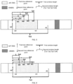
- the first time reference point and the second time reference point are both tn0
- the first window length and the second window length are Tw1 and Tw2 respectively
- a time range of the first reference signal is tr0 ⁇ tr1
- a time range agreed by the first time window information is tn0 ⁇ tn1
- a time range agreed by the second time window information is tn0 ⁇ tn2. Since the first reference signal is within the time ranges agreed by the first time window information and the second time window information, then a time range where the second reference signal may refer to the large scale property parameter(s) corresponding to the first reference signal is tr0 ⁇ tr1.
- the first time reference point and the second time reference point are both tn0
- the first window length and the second window length are Tw1 and Tw3 respectively
- a time range of the first reference signal is tr0 ⁇ tr1
- a time range agreed by the first time window is tn0 ⁇ tn1
- a time range agreed by the second time window information is tn0 ⁇ tn3. Since the first reference signal is all within the time range agreed by the first time window information, but only part of the first reference signal is within the time range agreed by the second time window information, then a time range where the second reference signal refers to the large scale property parameter(s) corresponding to the first reference signal is tr0 ⁇ tn3.
- the first time reference point and the second time reference point are both tn0
- the first window length and the second window length are Tw0 and Tw4 respectively
- a time range of the first reference signal is tr0 ⁇ tr1
- a time range agreed by the first time window is tm0 ⁇ tm1
- a time range agreed by the second time window information is tm0 ⁇ tm2. Since only part of the first reference signal is within the time ranges agreed by the first time window information and the second time window information, then a time range where the second reference signal refers to the large scale property parameter(s) corresponding to the first reference signal is tr0-tm2.
- a unit of the above-mentioned second window lengths can be a number of symbol, a number of time slot, a number of sub-frame, a number of frame, a second, a millisecond, a microsecond, etc.
- the second window length can be configured differently according to different large scale property parameters.
- different second window lengths for Doppler shift, Doppler spread, average delay, delay spread, and Spatial Rx parameter are configured respectively, and the second window lengths for different large scale property parameters meet a certain quantitative relationship.
- the base station indicates that DMRS and aperiodic CSI-RS for tracking (AP-TRS) meet a QCL type A relationship, and four different second window lengths configured for Doppler shift, Doppler spread, average delay, and delay spread are Tp1, Tp2, Tp3, Tp4, respectively, where Tp1 ⁇ Tp2 ⁇ Tp3 ⁇ Tp4.
- A-TRS aperiodic CSI-RS for tracking
- the first time reference point and the second time reference point are both tn0, the first window length is Tw1, a time range of AP-TRS is tr0-tr1, a time range agreed by the first time window information is tn0 ⁇ tf1, time ranges agreed by the four different second time window information are tn0 ⁇ tn1, tn0 ⁇ tn2, tn0 ⁇ tn3, tn0 ⁇ tn4 respectively.
- time ranges that can be referred to AP-TRS are tr0 ⁇ tn1, tr0 ⁇ tn2, tr0 ⁇ tn3, and tr0 ⁇ tn4.
- the second window lengths of the above-mentioned different large scale property parameters are not necessarily in an incrementing relationship according to the corresponding order of Doppler shift, Doppler spread, average delay, and delay spread, and may have other relationships.
- the base station can indicate that DMRS and AP-TRS meet a QCL type A relationship and that four different second window lengths configured for Doppler shift, Doppler spread, average delay, and delay spread are Tp1, Tp2, Tp3, Tp4, respectively, where Tp4 ⁇ Tp2 ⁇ Tp3 ⁇ Tp1, as shown in FIG. 6 .
- the second window lengths can also be differentially configured according to different large scale property parameter sets.
- large scale property parameter(s) in a same set have a same second window length
- large scale property parameters between different sets have different second window lengths
- the second window lengths of different sets meet a certain quantitative relationship.
- large scale property parameters can be divided into three sets according to ⁇ Doppler shift, Doppler spread ⁇ , ⁇ average delay, delay spread ⁇ , ⁇ Spatial Rx parameter ⁇ , and different second window lengths can be configured for multiple sets.
- the number of the sets and elements of the multiple sets involved in this grouping manner are not unique, and are only for demonstration.
- the base station indicates that DMRS and aperiodic CSI-RS for tracking (AP-TRS) meet a QCL type A relationship, and second window lengths configured for Doppler shift, Doppler spread, average delay, and delay spread are Tp1, Tp1, Tp2, Tp2, respectively, where Tp1 ⁇ Tp2.
- the first time reference point and the second time reference point are both tn0, the first window length is Tw1, a time range of AP-TRS is tr0 ⁇ tr1, a time range agreed by the first time window information is tn0 ⁇ tf1, and time ranges agreed by the second time window information are tn0 ⁇ tn1 and tn0 ⁇ tn2, respectively.
- time ranges that can be referred to TRS are tr0 ⁇ tn1, tr0 ⁇ tn1, tr0 ⁇ tn2, tr0 ⁇ tn2.
- the second window lengths can also be configured differentially according to different QCL types.
- different second window lengths are configured for QCL type A, QCL type B, QCL type C, and QCL type D, respectively, and second window lengths of different QCL types meet a certain quantitative relationship.
- Different QCL types may be two different QCL types of the same first reference signal that has a QCL relationship with the second reference signal, or may be QCL types of two different first reference signals that have a QCL relationship with the second reference signal, or the different QCL types is a QCL type of the same first reference signal that has a QCL relationship with two different second reference signals.
- the above different QCL types are QCL types of two different first reference signals that have a QCL relationship with the second reference signal, or two different QCL types of a same first reference signal that has a QCL relationship with the second reference signal type, then no matter whether the two QCL types are the same, they are considered different.
- the base station indicates that DMRS and aperiodic CSI-RS for tracking (AP-TRS) meet a QCL type A relationship and a QCL type D relationship simultaneously, and two different second window lengths Tp1, Tp2 are configured for QCL type A and QCL type D, then second window lengths of Doppler shift, Doppler spread, average delay, delay spread, Spatial Rx parameter are Tp1, Tp1, Tp1, Tp2, respectively, where Tp1>Tp2.
- the first time reference point and the second time reference point are both tn0
- the first window length is Tw1
- a time range of the AP-TRS is tr0 ⁇ tr1
- a time range agreed by the first time window information is tn0 ⁇ tf1
- time ranges agreed by the two different pieces of second time window information are tn0 ⁇ tm1 and tn0 ⁇ tm2 respectively.
- time ranges that can be referred to AP-TRS are tr0 ⁇ tm1, tr0 ⁇ tm1, tr0 ⁇ tm1, tr0 ⁇ tm1, and tr0 ⁇ tm2, respectively.
- the base station indicates that DMRS meets a QCL type A relationship and a QCL type D relationship with aperiodic CSI-RS for tracking (AP-TRS) and aperiodic CSI-RS for L1-RSRP computation (AP-CSI-RS-BM), respectively, and two different second window lengths Tu1 and Tu2 are configured for QCL type A and QCL type D, then second window lengths of Doppler shift, Doppler spread, average delay, delay spread and Spatial Rx parameter are Tu1, Tu1, Tu1, Tu1, Tu2, respectively, where Tu1 ⁇ Tu2.
- the first time reference point and the second time reference point are both tn0
- the first window length is Tw1
- time ranges of AP-TRS and AP-CSI-RS-BM are tr0 ⁇ tr1, ta0 ⁇ ta1, respectively
- a time range agreed by the first time window information is tn0 ⁇ tf1
- time ranges agreed by two different pieces of second time window information are tn0 ⁇ tk1 and tn0 ⁇ tk2, respectively.
- time ranges that are referred to AP-TRS are all tr0 ⁇ tk1
- a time range that can be referred to AP-CSI-RS-BM is ta0 ⁇ tk2.
- the base station indicates that DMRS, aperiodic CSI-RS for L1-RSRP computation (AP-CSI-RS-BM) and aperiodic CSI-RS for tracking (AP-TRS) all meet a QCL type A relationship, and two different second window lengths Tz1 and Tz2 are configured, then in two different situations, second window lengths of Doppler shift, Doppler spread, average delay, and delay spread are all Tz1 or Tz2, where Tz1>Tz2.
- AP-CSI-RS-BM aperiodic CSI-RS for L1-RSRP computation
- AP-TRS aperiodic CSI-RS for tracking
- the first window length is Tw1
- a time range of the AP-TRS is tr0 ⁇ tr1
- a time range agreed by the first time window information is tn0 ⁇ tf1
- time ranges agreed by two pieces of second time window information are tn0 ⁇ tk1 and tn0 ⁇ tk2, respectively.
- time ranges that are referred to AP-TRS are all tr0 ⁇ tk1
- AP-CSI-RS-BM needs to use parameters such as Doppler shift, Doppler spread, average delay, time ranges that are referred to AP-TRS are all tr0 ⁇ tk2.
- the above-mentioned second window lengths may also be configured differentially according to a periodic property of the first reference signal or the second reference signal.
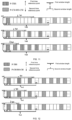
- the base station indicates that periodic CSI-RS for CSI acquisition (P-CSI-RS-CSI) and periodic CSI-RS for tracking (P-TRS) meet a QCL type A relationship, then the second window lengths can be associated with a period of P-CSI- RS-CSI or a period of P-TRS.
- the base station configures both the first time reference point and the second time reference point as tn0, the first window length is Tw0, and a time range agreed by the first time window information is tn0 ⁇ tf0.
- P-TRS periods of three different periods are 8*Tp_base, 2*Tp_base, Tp_base, respectively, a time domain range of the P-TRS in the first period is tr0 ⁇ tr1, and the second window lengths are Tp1, Tp2, Tp3 respectively, time ranges agreed by the second time window information are tn0 ⁇ tn1, tn0 ⁇ tn2, and tn0 ⁇ tn3 respectively.
- P-CSR-RS-CSI period is 2*Td_base.
- the Tp_base and Td_base are reference periods of P-TRS and P-CSR-RS-CSI, respectively, where Tp1>Tp2>Tp3.
- time ranges that are referred to P-TRS with three different periods are tr0 ⁇ tn1, tr0 ⁇ tn2, tr0 ⁇ tn3, respectively.
- Time domain ranges of different periodic P-TRS to which can be referred under different second time windows are different. It can be seen from the figure (i.e., FIG. 11 ) that when periods of P-TRS are 8*Tp_base, 2*Tp_base, and Tp_base, P-TRS where P-CSI-RS -CSI can be used to refer to large scale property parameter(s) within a time range agreed by the corresponding second time window information has complete TRS information in one period, complete TRS information in two periods, complete TRS information in one period plus partial TRS information in one period, respectively.
- the base station configures both the first time reference point and the second time reference point as tn0, the first window length is Tw1, and a time range agreed by the first time window information is tn0 ⁇ tf0.
- a period of P-TRS period is 2*Tp_base, and time domain range of P-TRS in the first period is tr0 ⁇ tr1.
- the P-CSR-RS-CSI periods of three different periods are Td_base, 2*Td_base, and 4*Td_base, respectively
- the second window lengths are Tp1, Tp2, and Tp3, respectively
- time ranges agreed by the second time window information are tn0 ⁇ tn1, tn0 ⁇ tn2, tn0 ⁇ tn3, respectively.
- Tp_base and Td_base are reference periods of P-TRS and P-CSR-RS-CSI, respectively, where Tp1>Tp2>Tp3.
- CSI-RS-CSI with three different periods needs to use parameters such as Doppler shift, Doppler spread, average delay, and delay spread, time ranges of P-TRS to which can be referred are tr0 ⁇ tn1, tr0 ⁇ tn2, tr0 ⁇ tn3, respectively.
- Time domain ranges of the periodic P-TRS to which can be referred under different second time windows are different. It can be seen from FIG.
- P-TRS when periods of P-CSI-RS-CSI are Td_base, 2*Td_base, 4*Td_base, P-TRS where P-CSI-RS -CSI can be used to refer to large scale property parameter(s) within a time range agreed by the corresponding second time window information has complete TRS information in three periods, complete TRS information in two periods, complete TRS information in one period, respectively.
- the base station indicates that semi-persistent CSI-RS for CSI acquisition (SP-CSI-RS-CSI) and P-TRS meet a QCL type A relationship, and thus, the second window lengths can be associated with a period of P-TRS.
- the base station configures both the first time reference point and the second time reference point as tn0, the first window length is Tw0, and a time range agreed by the first time window information is tn0 ⁇ tf0.
- P-TRS periods of three different periods are 8*Tp_base, 2*Tp_base, Tp_base, respectively, a time domain range of P-TRS in the first period is tr0 ⁇ tr1, and the second window lengths are Tp1, Tp2, Tp3, respectively, time ranges agreed by the second time window information are tn0 ⁇ tn1, tn0 ⁇ tn2, and tn0 ⁇ tn3, respectively.
- a period of SP-CSR-RS-CSI is 2*Td_base, where Tp_base and Td_base are reference periods of P-TRS and SP-CSR-RS-CSI, respectively, where Tp1>Tp2>Tp3.
- Tp_base and Td_base are reference periods of P-TRS and SP-CSR-RS-CSI, respectively, where Tp1>Tp2>Tp3.
- time ranges of P-TRS with three different periods to which can be referred are tr0 ⁇ tn1, tr0 ⁇ tn2, tr0 ⁇ tn3, respectively.
- Time domain ranges of different periodic P-TRS to which can be referred under different second time windows are different. It can be seen from the figure (i.e., FIG. 13 ) that when periods of P-TRS are 8*Tp_base, 2*Tp_base, and Tp_base, P-TRS where SP-CSI-RS -CSI can be used to refer to large scale property parameter(s) within a time range agreed by the corresponding second time window information has complete TRS information in one period, complete TRS information in two periods, complete TRS information in one period plus partial TRS information in one period.
- the base station indicates that aperiodic CSI-RS for CSI acquisition (AP-CSI-RS-CSI) and P-TRS meet a QCL type A relationship, and thus, the second window lengths can be associated with a period of P-TRS.
- the base station configures both the first time reference point and the second time reference point as tn0, the first window length is Tw0, and a time range agreed by the first time window information is tn0 ⁇ tf0.
- P-TRS periods of three different periods are 8*Tp_base, 2*Tp_base, Tp_base, respectively, a time domain range of P-TRS in the first period is tr0 ⁇ tr1, and the second window lengths are Tp1, Tp2, Tp3, respectively, time ranges agreed by the second time window information are tn0 ⁇ tn1, tn0 ⁇ tn2, and tn0 ⁇ tn3, respectively, where Tp_base is a reference period of P-TRS, where Tp1>Tp2>Tp3.
- a time range of P-TRS with three different periods to which can be referred are tr0 ⁇ tn1, tr0 ⁇ tn2, tr0 ⁇ tn3, respectively.
- Time domain ranges of different periodic P-TRS to which can be referred under different second time windows are different. It can be seen from the figure (i.e., FIG.
- P-TRS where AP-CSI-RS -CSI can be used to refer to large scale property parameter(s) within a time range agreed by the corresponding second time window information has complete TRS information in one period, complete TRS information in two periods, complete TRS information in one period plus partial TRS information in one period.
- a second window length may be associated with at least one of the factors, i.e., a large scale property parameter, a large scale property parameter set, a QCL type, and a period of a reference signal, where the reference signal may be the first reference signal, or the reference signal is the second reference signal.
- the second window length may be associated with a period of the first reference signal, or may also be associated with a period of the second reference signal; in a case where the first reference signal is a periodic signal and the second reference signal is an aperiodic signal or a semi-persistent signal, the second window length may be associated with a period of the first reference signal.
- association relationships between the second window length and factors may meet a certain functional relationship, where the functional relationship may include a positive correlation or a negative correlation.
- FIG. 15 is a flow chart of a method for determining a QCL relationship provided by an embodiment of the present application.
- the method may be applied to a second node (e.g., a base station).
- a second node e.g., a base station
- the method may include but is not limited to the following steps.
- the indication information in this step may include QCL association information, first time window information, and second time window information, where the QCL association information includes a first reference signal having the QCL relationship with a second reference signal, and a QCL type.
- the first time window information includes a first time reference point and a first window length
- the second time window information includes a second time reference point and a second window length.
- the second node can configure the indication information (or the second window length in the indication information) by virtue of static configuration, or the base station indicates the second window length by virtue of dynamic signaling after a set of parameter sets is configured, or the base station may jointly determine, with the first node, the second window length after a set of parameter sets is configured.
- the indication information can be sent to the first node, so as to enable the first node to determine the QCL relationship between the first reference signal and the second reference signal according to the QCL association information, the first time window information, and the second time window information included in the indication information.
- the embodiments of the present application provide a method for determining a QCL relationship, where the method may include: configuring indication information; and sending the indication information.
- the indication information includes QCL association information, first time window information and second time window information, and the QCL association information includes a first reference signal having a QCL relationship with the second reference signal, and a QCL type.
- the aforementioned QCL type includes at least one of QCL type A, QCL type B, QCL type C, and QCL type D.
- the above-mentioned first reference signal may include any one of SSB, CSI-RS, and DMRS
- the second reference signal may include any one of DMRS, CSI-RS, and PTRS.
- the first reference signal can be understood as a source signal
- the second reference signal can be understood as a target signal, i.e., the second reference signal can determine the large scale property parameter(s) of the second reference signal through the measurement result of the large scale property parameter(s) of the first reference signal.
- the above-mentioned first time window information is used to determine a first limiting condition that the first reference signal has the QCL relationship with the second reference signal
- the second time window information is used to determine a second limiting condition that the second reference signal has the QCL relationship with the first reference signal
- first reference signal and the second reference signal mentioned above having a QCL relationship can be understood as the first reference signal and the second reference signal meeting the first limiting condition and second limiting condition mentioned above, simultaneously.
- the first time reference point in the first time window information may include a receiving timepoint of a signaling indicating that the first reference signal and the second reference signal have the QCL relationship, or the first time reference point includes a timepoint of determining the large scale property parameter(s) of the second reference signal.
- the second time reference point in the second time window information may include a receiving timepoint of a signaling that the first reference signal and the second reference signal have the QCL relationship, or the second time reference point includes a beginning or ending timepoint of the nth symbol or the nth time slot of the first reference signal; where n is a positive integer less than the number of symbols or time slots occupied by the first reference signal.
- the unit of the above-mentioned second window length may be a number of symbols, a number of time slot, a number of subframe, a number of frame , a second, a millisecond, a microsecond, etc.
- the second window length may be many different configurations for the second window length to achieve differentiated configurations in different scenarios.
- the second window length can be configured differently according to different large scale property parameters.
- different second window lengths for Doppler shift, Doppler spread, average delay, delay spread, and Spatial Rx parameter are configured respectively, and the second window lengths for different large scale property parameters meet a certain quantitative relationship.
- the second window length can also be differentially configured according to different large scale property parameter sets.
- the large scale property parameter(s) in the same set has/have the same second window length
- the large scale property parameters between different sets have different second window lengths
- the second window lengths of different sets meet a certain quantitative relationship.
- the large scale property parameters can be categorized into three sets according to ⁇ Doppler shift, Doppler spread ⁇ , ⁇ average delay, delay spread ⁇ , ⁇ Spatial Rx parameter ⁇ , and different second window lengths can be configured for multiple sets.
- the second window length can also be configured differently according to different QCL types.
- different second window lengths are configured for QCL type A, QCL type B, QCL type C, and QCL type D, respectively, and the second window lengths for different QCL types meet a certain quantitative relationship.
- Different QCL types may be two different QCL types of the same first reference signal that has a QCL relationship with the second reference signal, or may be QCL types of two different first reference signals that have a QCL relationship with the second reference signal, or the different QCL types is a QCL type of the same first reference signal that has a QCL relationship with two different second reference signals.
- the above different QCL types are QCL types of two different first reference signals that have a QCL relationship with the second reference signal, or two different QCL types of a same first reference signal having a QCL relationship with the second reference signal type, then no matter whether the two QCL types are the same, they are considered different.
- the aforementioned second window length may also be configured differentially according to the periodic characteristics of the first reference signal or the second reference signal.
- the base station indicates that periodic CSI-RS for CSI acquisition (P-CSI-RS-CSI) and periodic CSI-RS for tracking (P-TRS) meet a QCL type A relationship, then the second window length can be associated with a period of P-CSI-RS-CSI or a period of P-TRS.
- the second window length can be associated with a period of the first reference signal, and can also be associated with a period of the second reference signal; in a case where the first reference signal is a periodic signal and the second reference signal is an aperiodic signal or a semi-persistent signal, the second window length may be associated with a period of the first reference signal.
- the second window length may be associated with at least one of factors such as a large scale property parameter, a large scale property parameter set, a QCL type, and a period of a reference signal.
- the association relationship may include that the second window length meets a functional relationship with at least one of a large scale property parameter, a large scale property parameter set, a QCL type, and a period of a reference signal.
- the functional relationship may be a positive correlation or a negative correlation.
- the reference signal may be a first reference signal, or the reference signal may be a second reference signal.
- the second time reference point includes a beginning or ending timepoint specifying the nth symbol or the nth time slot of the kth period of the first reference signal; where n is a positive integer less than the number of symbols or time slots occupied by the first reference signal in one period, and k is a positive integer.
- the base station can indicate second time reference points in the following different situations, for example, DMRS and AP-TRS meet a Type A relationship and the second time reference point and the first time reference point are the same, or DMRS and AP-TRS meet a Type A relationship and the second time reference point is a beginning timepoint of the first symbol of AP-TRS, or DMRS and P-TRS meet a Type A relationship and the second time reference point is an ending timepoint of the last symbol in the first period of P-TRS, or DMRS and P-TRS meet a Type A relationship and the second time reference point is a beginning time of the first symbol in the second period of P-TRS.
- the first time reference points are all tn0
- the first window lengths are all Tw0
- the second window lengths are all Tp0
- the second time reference points are tm0, tm1, tm2, tm3 respectively
- time ranges agreed by the first time window information are all tn0 ⁇ tf0
- time ranges agreed by the second time window information are tn0 ⁇ tm0, tn1 ⁇ tm1, tn2 ⁇ tm2, and tn3 ⁇ tm3, respectively.
- time ranges that can be referred to the corresponding second reference signals as tn0 ⁇ tm0, tn1 ⁇ tm1, tn2 ⁇ m2, tn3 ⁇ tm3.
- a period of the above-mentioned reference signal is a period of the first reference signal; in a case where the second reference signal is a periodic signal, a period of the reference signal is a period of the second reference signal.
- FIG. 17 is a device for determining a QCL relationship provided by an embodiment of the present application. As shown in FIG. 17 , the device may include: an acquiring module 1701 and a determining module 1702;
- the above-mentioned first reference signal may include any one of SSB, CSI-RS, and DMRS
- the second reference signal may include any one of DMRS, CSI-RS, and PTRS.
- the second reference signal may determine the large scale property parameter(s) of the second reference signal through the measurement result of the large scale property parameter(s) of the first reference signal.
- the above-mentioned first time window information includes a first time reference point and a first window length, where the first time window information is used to determine a first limiting condition that the first reference signal has the QCL relationship with the second reference signal; the first time reference point includes a receiving timepoint of a signaling indicating that the first reference signal and the second reference signal have the QCL relationship, or the first time reference point includes a timepoint where the large scale property parameter(s) of the second reference signal is/are determined.
- the second time window information includes a second time reference point and a second window length, where the second time window information is used to determine a second limiting condition that the second reference signal has the QCL relationship with the first reference signal; the second time reference point includes a receiving timepoint of a signaling indicating that the first reference signal and the second reference signal have the QCL relationship, or the second time reference point includes a beginning or ending timepoint of the nth symbol or the nth time slot of the first reference signal; where n is a positive integer less than the number of symbols or time slots occupied by the first reference signal.
- the second time reference point includes a beginning or ending timepoint specifying the nth symbol or the nth time slot of the kth period of the first reference signal; where n is a positive integer less than the number of symbols or time slots occupied by the first reference signal in one period, and k is a positive integer.
- first reference signal and the second reference signal above having the QCL relationship may be understood as the first reference signal and the second reference signal simultaneously meeting the first limiting condition and the second limiting condition.
- the second window length may be associated with at least one of a large scale property parameter, a large scale property parameter set, a QCL type, and a period of the reference signal, where the association relationship may be understood as that the second window length can meet a functional relationship with at least one of the large scale property parameter, the large scale property parameter set, the QCL type, and the period of the reference signal.
- the above-mentioned reference signal may be a first reference signal, or the reference signal may be a second reference signal.
- the second window length may be associated with a period of the first reference signal, or may be associated with a period of the second reference signal.
- the second window length may be associated with a period of the first reference signal, that is, in a case where the first reference signal is a periodic signal, the period of the above-mentioned reference signal is the period of the first reference signal.
- the second reference signal is a periodic signal
- the period of the reference signal is the period of the second reference signal.
- the device for determining the QCL relationship provided by this embodiment is configured to implement the method for determining the QCL relationship in the embodiment shown in FIG. 1 , and its implementation principle and technical effect are similar, and will not be repeated herein.
- FIG. 18 is a device for determining a QCL relationship provided by an embodiment of the present application. As shown in FIG. 18 , the device may include: a configuring module 1801 and a sending module 1802;
- the first reference signal may include any one of SSB, CSI-RS, and DMRS
- the second reference signal may include any one of DMRS, CSI-RS, and PTRS.
- the second reference signal may determine the large scale property parameter(s) of the second reference signal through the measurement result of the large scale property parameter(s) of the first reference signal.
- the first time window information includes a first time reference point and a first window length, where the first time window information is used to determine a first limiting condition that the first reference signal has a QCL relationship with the second reference signal; the first time reference point includes a receiving timepoint of a signaling indicating the first reference signal and the second reference signal have the QCL relationship, or, the first time reference point includes a timepoint where the large scale property parameter(s) of the second reference signal is/are determined.
- the second time window information includes a second time reference point and a second window length, where the second time window information is used to determine a second limiting condition that the second reference signal has the QCL relationship with the first reference signal.
- the second time reference point includes a receiving timepoint of a signaling indicating that the first reference signal and the second reference signal have a QCL relationship, or, the second time reference point includes a beginning or ending timepoint of the nth symbol or the nth time slot of the first reference signal; where n is a positive integer less than the number of symbols or time slots occupied by the first reference signal.
- the second time reference point includes a beginning or ending timepoint specifying the nth symbol or the nth time slot of the kth period of the first reference signal; where n is a positive integer less than the number of symbols or time slots occupied by the first reference signal in one period, and k is a positive integer.
- the first reference signal and the second reference signal above having the QCL relationship includes: the first reference signal and the second reference signal simultaneously meeting the first limiting condition and the second limiting condition.
- the second window length is associated with at least one of a large scale property parameter, a large scale property parameter set, a QCL type, and a period of the reference signal, where the association relationship may include the second window length meeting the functional relationship with at least one of the large scale property parameters, the large scale property parameter set, the QCL type, and the period of the reference signal.
- the above-mentioned reference signal may be a first reference signal, or the reference signal may be a second reference signal.
- the second window length may be associated with a period of the first reference signal, or may be associated with a period of the second reference signal.
- the first reference signal is a periodic signal
- the second reference signal is an aperiodic signal or a semi-persistent signal
- the second window length may be associated with a period of the first reference signal.
- the period of the above-mentioned reference signal is the period of the first reference signal.
- the period of the reference signal is the period of the second reference signal.
- the device for determining the QCL relationship provided by this embodiment is configured to implement the method for determining the QCL relationship in the embodiment shown in FIG. 15 , and its implementation principle and technical effect are similar, and will not be repeated herein.
- FIG. 19 is a schematic structural diagram of a network node provided by an embodiment.
- the node includes a processor 1901 and a memory 1902; the number of processors 1901 in the node can be one or more, and in FIG. 19 , one processor 1901 is taken as an example; the processor 1901 and the memory 1902 in a node can be connected through a bus or in other ways, and the connection through a bus is taken as an example in FIG. 19 .
- the memory 1902 can be configured to store software programs, computer-executable programs and modules, such as program instructions/modules corresponding to the method for determining the QCL relationship in the embodiment of FIG. 1 or FIG. 15 of the present application (for example, the acquiring module 1701 and the determining module 1702 or the configuring module 701 and the sending module 702 the configuration module 1801 and the sending module 1802) in the device for determining the QCL relationship.
- the processor 1901 implements the above-mentioned method for determining the QCL relationship by running the software programs, instructions and modules stored in the memory 1902.
- the memory 1902 may mainly include an area for storing programs and an area for storing data, where the area for storing programs may store an operating system, and an application program required by at least one function unit, and the area for storing data can store data, such as data created according to the usage of the set-top box.
- the memory 1902 may include a high-speed random access memory, and may also include a non-volatile memory, such as at least one of magnetic disk storage device, a flash memory device, or other non-volatile solid state storage devices.
- the processor in the above node may also implement the above method for determining the QCL relationship through its internal hardware circuits, such as logic circuits, and gate circuits.
- the embodiments of the present application further provide a readable and writable storage medium, configured as a computer storage, the storage medium stores one or more programs, where the one or more programs can be executed by the one or more processors to perform the above method for determining the QCL relationship in the above embodiments.
- division between functional modules/units mentioned in the above description does not necessarily correspond to division of physical components; for example, one physical component may have multiple functions, or one function or step may be performed cooperatively by several physical components.
- Some or all of the hardware components may be implemented as software executed by a processor, such as a central processing unit, a digital signal processor, or a microprocessor, or implemented as a hardware, or implemented as an integrated circuit, such as an application-specific integrated circuit.
- a processor such as a central processing unit, a digital signal processor, or a microprocessor
- Such software may be distributed on a computer readable medium, which may include a computer storage medium (or a non-transitory medium) and a communication medium (or a transitory medium).
- computer storage medium includes volatile medium and nonvolatile medium, removable medium and non-removable medium implemented in any method or technology for storage of information, such as computer readable instructions, data structures, program modules, or other data.
- the computer storage media includes, but is not limited to, RAMs, ROMs, EEPROMs, flash memories or other memory technologies, CD-ROMs, digital versatile disks (DVD) or other optical disk storages, magnetic cartridges, tapes, magnetic disk storages or other magnetic storage devices, or any other media that are used to store desired information and can be accessed by a computer.
- communication media typically include computer readable instructions, data structures, program modules, or other data in a modulated data signal such as a carrier wave or other transport mechanism, and may include any information delivery media.
Landscapes
- Engineering & Computer Science (AREA)
- Signal Processing (AREA)
- Computer Networks & Wireless Communication (AREA)
- Mobile Radio Communication Systems (AREA)
- Signal Processing For Digital Recording And Reproducing (AREA)
- Debugging And Monitoring (AREA)
- Indexing, Searching, Synchronizing, And The Amount Of Synchronization Travel Of Record Carriers (AREA)
Applications Claiming Priority (2)
| Application Number | Priority Date | Filing Date | Title |
|---|---|---|---|
| CN202011633396.5A CN112822779A (zh) | 2020-12-31 | 2020-12-31 | Qcl关系确定方法、装置、节点和存储介质 |
| PCT/CN2021/141204 WO2022143459A1 (zh) | 2020-12-31 | 2021-12-24 | Qcl关系确定方法、装置、节点和存储介质 |
Publications (1)
| Publication Number | Publication Date |
|---|---|
| EP4274336A1 true EP4274336A1 (de) | 2023-11-08 |
Family
ID=75856717
Family Applications (1)
| Application Number | Title | Priority Date | Filing Date |
|---|---|---|---|
| EP21914196.7A Pending EP4274336A1 (de) | 2020-12-31 | 2021-12-24 | Verfahren und vorrichtung zur bestimmung von qcl-beziehungen, knoten und speichermedium |
Country Status (5)
| Country | Link |
|---|---|
| US (1) | US20240072874A1 (de) |
| EP (1) | EP4274336A1 (de) |
| CN (1) | CN112822779A (de) |
| CA (1) | CA3202934A1 (de) |
| WO (1) | WO2022143459A1 (de) |
Families Citing this family (2)
| Publication number | Priority date | Publication date | Assignee | Title |
|---|---|---|---|---|
| CN112822779A (zh) * | 2020-12-31 | 2021-05-18 | 中兴通讯股份有限公司 | Qcl关系确定方法、装置、节点和存储介质 |
| CN112865941A (zh) * | 2020-12-31 | 2021-05-28 | 中兴通讯股份有限公司 | 大尺度特性参数测量方法、装置、节点和存储介质 |
Family Cites Families (3)
| Publication number | Priority date | Publication date | Assignee | Title |
|---|---|---|---|---|
| US10419162B2 (en) * | 2017-11-27 | 2019-09-17 | Nokia Technologies Oy | Dynamic scheduling based QCL association for tracking reference signal |
| CN111835482A (zh) * | 2019-08-02 | 2020-10-27 | 维沃移动通信有限公司 | 准共址qcl信息确定方法、配置方法及相关设备 |
| CN112822779A (zh) * | 2020-12-31 | 2021-05-18 | 中兴通讯股份有限公司 | Qcl关系确定方法、装置、节点和存储介质 |
-
2020
- 2020-12-31 CN CN202011633396.5A patent/CN112822779A/zh active Pending
-
2021
- 2021-12-24 WO PCT/CN2021/141204 patent/WO2022143459A1/zh active Application Filing
- 2021-12-24 US US18/259,872 patent/US20240072874A1/en active Pending
- 2021-12-24 EP EP21914196.7A patent/EP4274336A1/de active Pending
- 2021-12-24 CA CA3202934A patent/CA3202934A1/en active Pending
Also Published As
| Publication number | Publication date |
|---|---|
| WO2022143459A1 (zh) | 2022-07-07 |
| CA3202934A1 (en) | 2022-07-07 |
| US20240072874A1 (en) | 2024-02-29 |
| CN112822779A (zh) | 2021-05-18 |
Similar Documents
| Publication | Publication Date | Title |
|---|---|---|
| US20220330300A1 (en) | Transmission method, apparatus, first communication node, second communication node, and medium | |
| CN109219970B (zh) | 移动通信中跨链路干扰测量方法及设备 | |
| EP4274336A1 (de) | Verfahren und vorrichtung zur bestimmung von qcl-beziehungen, knoten und speichermedium | |
| US20210105816A1 (en) | Method and equipment for channel sensing and signal transmission | |
| US20220110067A1 (en) | Method and device for estimating inter-terminal path loss in wireless communication system | |
| EP3579469B1 (de) | Drahtloskommunikationsverfahren und -vorrichtung | |
| US20140219237A1 (en) | Method and Apparatus for Establishing a Time-Frequency Reference Signal Pattern Configuration in a Carrier Extension or Carrier Segment | |
| US10581573B2 (en) | Apparatus, terminal and signal transmitting and receiving method thereof in a wireless communication system | |
| US9648628B2 (en) | Inter-link interference information sharing-based link scheduling method and apparatus for use in wireless communication system | |
| KR20210006968A (ko) | 채널 구성 방법 및 장치, 전력 제어 방법 및 장치, 사용자 장비, 기지국 및 저장 매체 | |
| US20140086371A1 (en) | Interference cancellation apparatus and receiver | |
| WO2022022732A1 (zh) | 一种qcl指示方法及相关设备 | |
| US11943174B2 (en) | Dynamic parameter adaptation for aperiodic doppler tracking sounding reference signal resource sets | |
| US9225492B2 (en) | Cyclic prefix based opportunistic transmission/reception scheme for interference cancelation | |
| WO2022143288A1 (zh) | 大尺度特性参数测量方法、装置、节点和存储介质 | |
| US20140348273A1 (en) | Offset estimation using channel state information reference symbols and demodulation reference symbols | |
| CN111988852A (zh) | 一种信息上报的方法及装置 | |
| CN102821392A (zh) | 小区间干扰抑制的下行业务传输方法及装置 | |
| CN112583536B (zh) | 反馈信息处理方法及通信装置 | |
| US11381980B2 (en) | Method and apparatus for establishing cell of base station in wireless communication system | |
| WO2024065711A1 (zh) | 一种测距方法、装置和系统 | |
| WO2022236656A1 (en) | Methods, devices and systems for reporting frequency offset | |
| WO2024020718A1 (en) | Reference signals with different resource densities | |
| WO2023206547A1 (zh) | 相对位置的定位方法、装置、设备和介质 | |
| CN118119860A (zh) | 一种测距方法、装置和系统 |
Legal Events
| Date | Code | Title | Description |
|---|---|---|---|
| STAA | Information on the status of an ep patent application or granted ep patent |
Free format text: STATUS: THE INTERNATIONAL PUBLICATION HAS BEEN MADE |
|
| PUAI | Public reference made under article 153(3) epc to a published international application that has entered the european phase |
Free format text: ORIGINAL CODE: 0009012 |
|
| STAA | Information on the status of an ep patent application or granted ep patent |
Free format text: STATUS: REQUEST FOR EXAMINATION WAS MADE |
|
| 17P | Request for examination filed |
Effective date: 20230629 |
|
| AK | Designated contracting states |
Kind code of ref document: A1 Designated state(s): AL AT BE BG CH CY CZ DE DK EE ES FI FR GB GR HR HU IE IS IT LI LT LU LV MC MK MT NL NO PL PT RO RS SE SI SK SM TR |
|
| DAV | Request for validation of the european patent (deleted) | ||
| DAX | Request for extension of the european patent (deleted) |