EP4273974A1 - Fuel cell system - Google Patents
Fuel cell system Download PDFInfo
- Publication number
- EP4273974A1 EP4273974A1 EP22756392.1A EP22756392A EP4273974A1 EP 4273974 A1 EP4273974 A1 EP 4273974A1 EP 22756392 A EP22756392 A EP 22756392A EP 4273974 A1 EP4273974 A1 EP 4273974A1
- Authority
- EP
- European Patent Office
- Prior art keywords
- air
- fuel cell
- cell system
- housing
- stack
- Prior art date
- Legal status (The legal status is an assumption and is not a legal conclusion. Google has not performed a legal analysis and makes no representation as to the accuracy of the status listed.)
- Granted
Links
Images


Classifications
-
- B—PERFORMING OPERATIONS; TRANSPORTING
- B01—PHYSICAL OR CHEMICAL PROCESSES OR APPARATUS IN GENERAL
- B01D—SEPARATION
- B01D45/00—Separating dispersed particles from gases or vapours by gravity, inertia, or centrifugal forces
- B01D45/12—Separating dispersed particles from gases or vapours by gravity, inertia, or centrifugal forces by centrifugal forces
- B01D45/16—Separating dispersed particles from gases or vapours by gravity, inertia, or centrifugal forces by centrifugal forces generated by the winding course of the gas stream, the centrifugal forces being generated solely or partly by mechanical means, e.g. fixed swirl vanes
-
- H—ELECTRICITY
- H01—ELECTRIC ELEMENTS
- H01M—PROCESSES OR MEANS, e.g. BATTERIES, FOR THE DIRECT CONVERSION OF CHEMICAL ENERGY INTO ELECTRICAL ENERGY
- H01M8/00—Fuel cells; Manufacture thereof
- H01M8/04—Auxiliary arrangements, e.g. for control of pressure or for circulation of fluids
- H01M8/04082—Arrangements for control of reactant parameters, e.g. pressure or concentration
- H01M8/04089—Arrangements for control of reactant parameters, e.g. pressure or concentration of gaseous reactants
-
- B—PERFORMING OPERATIONS; TRANSPORTING
- B01—PHYSICAL OR CHEMICAL PROCESSES OR APPARATUS IN GENERAL
- B01D—SEPARATION
- B01D45/00—Separating dispersed particles from gases or vapours by gravity, inertia, or centrifugal forces
- B01D45/12—Separating dispersed particles from gases or vapours by gravity, inertia, or centrifugal forces by centrifugal forces
-
- B—PERFORMING OPERATIONS; TRANSPORTING
- B01—PHYSICAL OR CHEMICAL PROCESSES OR APPARATUS IN GENERAL
- B01D—SEPARATION
- B01D45/00—Separating dispersed particles from gases or vapours by gravity, inertia, or centrifugal forces
- B01D45/18—Cleaning-out devices
-
- H—ELECTRICITY
- H01—ELECTRIC ELEMENTS
- H01M—PROCESSES OR MEANS, e.g. BATTERIES, FOR THE DIRECT CONVERSION OF CHEMICAL ENERGY INTO ELECTRICAL ENERGY
- H01M8/00—Fuel cells; Manufacture thereof
- H01M8/04—Auxiliary arrangements, e.g. for control of pressure or for circulation of fluids
- H01M8/04082—Arrangements for control of reactant parameters, e.g. pressure or concentration
- H01M8/04089—Arrangements for control of reactant parameters, e.g. pressure or concentration of gaseous reactants
- H01M8/04097—Arrangements for control of reactant parameters, e.g. pressure or concentration of gaseous reactants with recycling of the reactants
-
- H—ELECTRICITY
- H01—ELECTRIC ELEMENTS
- H01M—PROCESSES OR MEANS, e.g. BATTERIES, FOR THE DIRECT CONVERSION OF CHEMICAL ENERGY INTO ELECTRICAL ENERGY
- H01M8/00—Fuel cells; Manufacture thereof
- H01M8/04—Auxiliary arrangements, e.g. for control of pressure or for circulation of fluids
- H01M8/04082—Arrangements for control of reactant parameters, e.g. pressure or concentration
- H01M8/04089—Arrangements for control of reactant parameters, e.g. pressure or concentration of gaseous reactants
- H01M8/04111—Arrangements for control of reactant parameters, e.g. pressure or concentration of gaseous reactants using a compressor turbine assembly
-
- H—ELECTRICITY
- H01—ELECTRIC ELEMENTS
- H01M—PROCESSES OR MEANS, e.g. BATTERIES, FOR THE DIRECT CONVERSION OF CHEMICAL ENERGY INTO ELECTRICAL ENERGY
- H01M8/00—Fuel cells; Manufacture thereof
- H01M8/04—Auxiliary arrangements, e.g. for control of pressure or for circulation of fluids
- H01M8/04082—Arrangements for control of reactant parameters, e.g. pressure or concentration
- H01M8/04089—Arrangements for control of reactant parameters, e.g. pressure or concentration of gaseous reactants
- H01M8/04119—Arrangements for control of reactant parameters, e.g. pressure or concentration of gaseous reactants with simultaneous supply or evacuation of electrolyte; Humidifying or dehumidifying
-
- H—ELECTRICITY
- H01—ELECTRIC ELEMENTS
- H01M—PROCESSES OR MEANS, e.g. BATTERIES, FOR THE DIRECT CONVERSION OF CHEMICAL ENERGY INTO ELECTRICAL ENERGY
- H01M8/00—Fuel cells; Manufacture thereof
- H01M8/04—Auxiliary arrangements, e.g. for control of pressure or for circulation of fluids
- H01M8/04082—Arrangements for control of reactant parameters, e.g. pressure or concentration
- H01M8/04089—Arrangements for control of reactant parameters, e.g. pressure or concentration of gaseous reactants
- H01M8/04119—Arrangements for control of reactant parameters, e.g. pressure or concentration of gaseous reactants with simultaneous supply or evacuation of electrolyte; Humidifying or dehumidifying
- H01M8/04126—Humidifying
-
- H—ELECTRICITY
- H01—ELECTRIC ELEMENTS
- H01M—PROCESSES OR MEANS, e.g. BATTERIES, FOR THE DIRECT CONVERSION OF CHEMICAL ENERGY INTO ELECTRICAL ENERGY
- H01M8/00—Fuel cells; Manufacture thereof
- H01M8/04—Auxiliary arrangements, e.g. for control of pressure or for circulation of fluids
- H01M8/04082—Arrangements for control of reactant parameters, e.g. pressure or concentration
- H01M8/04089—Arrangements for control of reactant parameters, e.g. pressure or concentration of gaseous reactants
- H01M8/04119—Arrangements for control of reactant parameters, e.g. pressure or concentration of gaseous reactants with simultaneous supply or evacuation of electrolyte; Humidifying or dehumidifying
- H01M8/04156—Arrangements for control of reactant parameters, e.g. pressure or concentration of gaseous reactants with simultaneous supply or evacuation of electrolyte; Humidifying or dehumidifying with product water removal
- H01M8/04164—Arrangements for control of reactant parameters, e.g. pressure or concentration of gaseous reactants with simultaneous supply or evacuation of electrolyte; Humidifying or dehumidifying with product water removal by condensers, gas-liquid separators or filters
-
- H—ELECTRICITY
- H01—ELECTRIC ELEMENTS
- H01M—PROCESSES OR MEANS, e.g. BATTERIES, FOR THE DIRECT CONVERSION OF CHEMICAL ENERGY INTO ELECTRICAL ENERGY
- H01M8/00—Fuel cells; Manufacture thereof
- H01M8/04—Auxiliary arrangements, e.g. for control of pressure or for circulation of fluids
- H01M8/04082—Arrangements for control of reactant parameters, e.g. pressure or concentration
- H01M8/04201—Reactant storage and supply, e.g. means for feeding, pipes
-
- H—ELECTRICITY
- H01—ELECTRIC ELEMENTS
- H01M—PROCESSES OR MEANS, e.g. BATTERIES, FOR THE DIRECT CONVERSION OF CHEMICAL ENERGY INTO ELECTRICAL ENERGY
- H01M8/00—Fuel cells; Manufacture thereof
- H01M8/06—Combination of fuel cells with means for production of reactants or for treatment of residues
- H01M8/0662—Treatment of gaseous reactants or gaseous residues, e.g. cleaning
-
- H—ELECTRICITY
- H01—ELECTRIC ELEMENTS
- H01M—PROCESSES OR MEANS, e.g. BATTERIES, FOR THE DIRECT CONVERSION OF CHEMICAL ENERGY INTO ELECTRICAL ENERGY
- H01M2250/00—Fuel cells for particular applications; Specific features of fuel cell system
- H01M2250/20—Fuel cells in motive systems, e.g. vehicle, ship, plane
-
- Y—GENERAL TAGGING OF NEW TECHNOLOGICAL DEVELOPMENTS; GENERAL TAGGING OF CROSS-SECTIONAL TECHNOLOGIES SPANNING OVER SEVERAL SECTIONS OF THE IPC; TECHNICAL SUBJECTS COVERED BY FORMER USPC CROSS-REFERENCE ART COLLECTIONS [XRACs] AND DIGESTS
- Y02—TECHNOLOGIES OR APPLICATIONS FOR MITIGATION OR ADAPTATION AGAINST CLIMATE CHANGE
- Y02E—REDUCTION OF GREENHOUSE GAS [GHG] EMISSIONS, RELATED TO ENERGY GENERATION, TRANSMISSION OR DISTRIBUTION
- Y02E60/00—Enabling technologies; Technologies with a potential or indirect contribution to GHG emissions mitigation
- Y02E60/30—Hydrogen technology
- Y02E60/50—Fuel cells
Definitions
- the present technology relates to a fuel cell system.
- the present technology can filter foreign substances contained in air that is supplied to a stack. Therefore, the present technology can improve a function of the stack and extend the lifetime of the stack.
- Electrical energy can be produced in a variety of ways.
- the electrical energy is mainly produced by utilizing petroleum.
- the petroleum is predicted to be depleted someday and has an adverse effect on an environment, development of alternative energy to replace petroleum is required.
- a fuel cell produces electrical energy by utilizing a stack configured of an anode, a cathode, and an electrolyte. According to the principle of the fuel cell, hydrogen is supplied to the anode and oxygen is supplied to the cathode. Therefore, hydrogen ions and electrons are emitted from the anode to generate current, hydrogen ions and oxygen are coupled to produce water vapor in the cathode, and the water vapor is discharged.
- Such a fuel cell has advantages such as high efficiency, adjustable capacity, use of various fuels, discharged material close to an environmentally friendly material, and continuous charging.
- the fuel cell has several advantages, but there is a problem to be solved.
- the problem is the supply of foreign substances to the stack. When the foreign substances are supplied to the stack, the performance and lifetime of the stack are degraded.
- An object of the present invention is to provide a fuel cell system capable of preventing foreign substances from being supplied to a stack and extending the performance and lifetime of the stack.
- a fuel cell system includes a fuel cell stack, a hydrogen supply unit configured to supply hydrogen to the stack, and an air supply unit configured to supply air to the stack.
- the fuel cell system includes: a gas-liquid separator disposed between the stack and the air supply unit and configured to remove foreign substances from the air supplied to the stack.
- the gas-liquid separator may include a housing, an air inlet formed on one side of the housing, an air outlet formed on the other side of the housing, and an air rotation portion disposed in the air inlet and configured to rotate air supplied through the air inlet.
- the air rotation portion may be a closed block having an inclined shape.
- the housing may include an outer housing and an inner housing disposed inside the outer housing, the air inlet may be formed in the outer housing, the air outlet may be formed in the inner housing, the air outlet may be formed to pass through the outer housing at a center of the inner housing, and the air inlet may be located at a position biased from a center of the outer housing.
- the air rotation portion may be disposed along a circumference of the inner housing on the upper side of the inner housing.
- the air rotation portion may be a closed block inclined in a curved shape.
- a variable flow path container may be disposed between the inner housing and the air outlet.
- variable flow path container may have a diameter increasing from a lower side to the upper side.
- the air inlet further may include a filter configured to filter foreign substances.
- the air supply unit may include an air compressor configured to supply compressed air; and a fuel cell humidifier configured to receive the compressed air and supply moisture-containing air to the stack.
- the fuel cell system may include: a flow path configured to connect the gas-liquid separator to the air supply unit.
- FIG. 1 is a block diagram of a configuration of a fuel cell system according to an embodiment of the present invention.
- a fuel cell system may include a stack 100, a water tank 200, an air supply unit 300, a hydrogen supply unit 400, and a gas-liquid separator 500.
- the present invention may further include a water pump 600.
- Each of the hydrogen supply unit 400 and the air supply unit 300 supplies hydrogen and air (oxygen) to the stack 100.
- the hydrogen supply unit 400 supplies stored hydrogen to the stack 100.
- the air supply unit 300 may include an air compressor 310 and a fuel cell humidifier 320.
- the fuel cell humidifier 320 may be connected to the water tank 200. Accordingly, the air supply unit 300 may supply moisture-containing air to the stack 100.
- the air compressor 310 may compress air and supply the compressed air to the fuel cell humidifier 320, and the fuel cell humidifier 320 may add moisture to the compressed air and supply the resultant air to the stack 100.
- the stack 100 is supplied with the hydrogen and the oxygen through an anode and a cathode, respectively.
- the hydrogen supplied to the anode loses electrons and becomes hydrogen ions.
- the hydrogen ions are located on the cathode side through the electrolyte, and hydrogen ions, oxygen, and electrons may be chemically bonded to form water vapor at the cathode.
- the water pump 600 serves to discharge water vapor generated in the stack 100.
- the water pump 600 may be connected to the fuel cell humidifier 320 through a flow path to supply moisture to the fuel cell humidifier 320 again.
- the gas-liquid separator 500 may be disposed between the stack 100 and the air supply unit 300. More precisely, the gas-liquid separator 500 may be disposed between the fuel cell humidifier 320 and the stack 100. The gas-liquid separator 500 may remove foreign substances from the air supplied to the stack 100.
- the air compressor 310 of the air supply unit 300 rotates an impeller to compress the air.
- metal pieces may be generated in the impeller due to friction, and the generated metal pieces may be moved in one direction by the impeller and supplied to the stack 100.
- the operation efficiency of the stack 100 supplied with the metal pieces may be degraded and the lifetime of the stack 100 may be shortened.
- the gas-liquid separator 500 is disposed between the air supply unit 300 and the stack 100 to remove foreign substances contained in the air to the stack 100. Therefore, the stack 100 can receive the air without foreign substances.
- the gas-liquid separator 500 is characterized by utilizing air that is moved rapidly due to the air supply unit 300. That is, the gas-liquid separator 500 of the present invention assigns rotation force to air moving at high speed so that foreign substances in the air are removed. Therefore, the gas-liquid separator 500 can cause the air with no foreign substances to be supplied to the stack 100.
- a flow path may be designed between the liquid separator 500 and the fuel cell humidifier 320.
- the gas-liquid separator 500 includes a discharge unit 560, and a flow path may be designed so that the discharge unit 560 is connected to the air supply unit 300. More precisely, a flow path of the discharge unit 560 may be connected to the fuel cell humidifier 320.
- the discharge unit 560 may be controlled and operated by a control signal from a control unit so that a gate is opened. Accordingly, moisture separated from the air by the gas-liquid separator 500 may be supplied to the fuel cell humidifier 320 again.
- a worker can separate the storage unit 550 (first embodiment) from a housing 540 or an outer housing 541 (second embodiment) to remove foreign substances and perform cleaning regardless of the above way.
- a filtering unit 570 may be installed in the storage unit 550 of the gas-liquid separator 500 so that the moisture is moved downward and the foreign substances are located only in the filtering unit 570.
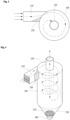
- FIG. 2 is a perspective view of the gas-liquid separator according to the first embodiment.
- FIG. 3 is a top cross-sectional view of the gas-liquid separator according to the first embodiment.
- the gas-liquid separator 500 includes an air inlet 510, an air outlet 520, and an air rotation portion 530.
- the air inlet 510 is a portion through which air containing foreign substances flows into the inside
- the air outlet 520 is a portion through which air from which foreign substances have been removed is discharged
- the air outlet 520 is connected to the stack 100.
- the air rotation portion 530 rapidly rotates the air flowing into the inside through the air inlet 510 so that foreign substances are removed from the air by centrifugal force.
- the gas-liquid separator 500 includes the air inlet 510, the air outlet 520, the air rotation portion 530, the housing 540, the storage unit 550, and the discharge unit 560.
- the housing 540 may have a cylindrical shape and may be formed to have an empty space therein.
- the air inlet 510 may be formed to extend from one side of the housing 540. Further, the air outlet 520 may be formed to extend upward from the housing 540.
- the air inlet 510 and the air outlet 520 can be seen from the outside of the housing 540.
- the air inlet 510 may communicates with one side of the housing 540, and the air outlet 520 may be formed to communicate with the top side and extend to the inside of the housing 540.
- a filter may be installed in the air inlet 510 to remove large foreign substances, in addition to small foreign substances.
- the filter is formed in the form of a net and can remove large foreign substances.
- an inclined closed block may be disposed in the air inlet 510.
- the closed block may be the air rotation portion 530 that applies rotation force to moving air. That is, as can be seen from FIG. 3 , the closed block may allow a size of a flow path of the air inlet 510 having a set size to continuously decrease from one side to the other side.
- the air passing through the air inlet 510 may pass through the flow path continuously decreasing due to the closed block, move between the housing 540 and the air outlet 520, where a size of a space decreases, and then, move while rotating between the housing 540 and the air outlet 520.
- foreign substances contained in the air are separated from the air due to centrifugal force, are located on the inner side of the housing 540, and fall.
- the air from which the foreign substances have been removed is moved to an inner space of the air outlet 520, and the air from which the foreign substances have been removed passes through the air outlet 520 and is supplied to the stack 100.
- the storage unit 550 is located below the housing 540.
- the storage unit 550 may have a shape in which the storage unit 550 is inclined toward a center, and a cross section of the storage unit 550 may be observed as a conical shape.
- the storage unit 550 and the housing 540 are in communication. This makes it possible for foreign substances separated from the air to be collected in the storage unit 550.
- the discharge unit 560 is positioned below the storage unit 550.
- the discharge unit 560 may be connected to the control unit even though the discharge unit 560 is not illustrated.
- the gate of the discharge unit 560 may be opened according to the control signal from the control unit. When the gate of the discharge unit 560 is opened, the foreign substances and the moisture located in the storage unit 550 may be moved to the outside of the storage unit 550.
- foreign substances and moisture may be supplied to the fuel cell humidifier 320 again without being filtered according to the opening of the gate of the discharge unit 560.
- the worker may remove the foreign substances by cleaning the fuel cell humidifier 320.
- the discharge unit 560 may be kept in a closed state of the gate without being operated so that the foreign substances and the moisture are stored in the storage unit 550.
- the storage unit 550 and the housing 540 may be configured of screw threads and coupled to or separated from each other. Accordingly, the worker may separate the storage unit 550 from the housing 540, remove the foreign substances from the storage unit 550, and then couple the storage unit 550 to the housing 540 again.
- gas-liquid separator 500 may reduce noise.
- the gas-liquid separator 500 may rotate the air to form a unique wavelength band so that air vibrating in a specific wavelength band can be offset and noise (particularly, a low-frequency sound range) can be reduced.
- the gas-liquid separator 500 may generate noise due to pulsation or the like when air is supplied through the air inlet 510, and a wavelength band that offsets a wavelength band in which noise is generated is formed due to an internal structure of the gas-liquid separator 500 so that the noise can be reduced.
- FIG. 4 is a perspective view of the gas-liquid separator according to a (1-1)-th embodiment.
- the filtering unit 570 may be disposed in the storage unit 550.
- the filtering unit 570 may pass moisture separated from the air due to rotation of the air so that only the foreign substances (metal pieces) can be located in the filtering unit 570.
- the gate may be opened according to the signal from the control unit and the discharge unit 560 may supply the moisture to the fuel cell humidifier 320 again when a set amount or more of moisture is located in the storage unit 550.
- the worker may separate the storage unit 550 from the housing 540, remove only the foreign substances located in the filtering unit 570, and then couple the storage unit 550 to the housing 540 again.
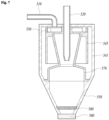
- FIG. 5 is a front cross-sectional view of a gas-liquid separator according to the second embodiment.
- FIG. 6 is a top cross-sectional view of the gas-liquid separator according to the second embodiment.
- the constitution of the present invention in the second embodiment is similar to the constitution of the invention according to the first embodiment. However, since there are some differences, different configurations will be mainly described hereinafter.
- the gas-liquid separator 500 according to the second embodiment is similar to the gas-liquid separator 500 according to the first embodiment, but may differ from the gas-liquid separator 500 according to the first embodiment in some structures.
- the gas-liquid separator 500 according to the second embodiment differs from the gas-liquid separator 500 according to the first embodiment in that the gas-liquid separator 500 according to the second embodiment performs removal of the foreign substances in the air twice.
- the gas-liquid separator 500 according to the second embodiment may further include a variable flow path container 580.
- the gas-liquid separator 500 includes an air inlet 510, an air outlet 520, an air rotation portion 530, an outer housing 541, an inner housing 545, a storage unit 550, a discharge unit 560, and a variable flow path container 580.
- a housing 540 according to the second embodiment includes an outer housing 541 and an inner housing 545.
- an air inlet 510 may be formed in the outer housing 541, and the air outlet 520 may be formed in the inner housing 545.
- the air inlet 510 may be located on the upper side of the outer housing 541. That is, the air inlet 510 according to the second embodiment may be located on the upper side of the outer housing 541 and move compressed air from the upper side to the lower side, unlike the air inlet 510 according to the first embodiment. A position of the air inlet 510 may be located at a position biased from a center of the outer housing 541, rather than the center.
- the inner housing 545 may be formed in a cylindrical shape.
- the inner housing 545 may be formed with an open lower side.
- the inner housing 545 may be aligned with the outer housing 541 and located on the inner side of the outer housing 541.
- a protrusion portion may be formed on the upper side of the inner housing 545.
- the protrusion portion of the inner housing 545 may come into contact with the inner side on the upper side of the outer housing 541 for coupling of the inner housing 545, and be located at a distance apart from the inner side on the upper side of the outer housing 541.
- the air outlet 520 may be formed on the upper side of the inner housing 545.
- the air outlet 520 may be located at a center of the inner housing 545. Therefore, when the inner housing 545 is aligned with the outer housing 541, the air outlet 520 is located at a position that is not on the same line as the air inlet 510.
- the air rotation portion 530 may be a closed block, as in the first embodiment.
- the closed block may include a curved inclination.
- the curved inclination of the closed block is formed on the inner side. That is, the curved inclination of the closed block is formed in a portion facing the air outlet 520. Further, the closed block may be located on the upper side of the inner housing 545 rather than the air inlet 510, unlike a case according to the first embodiment.
- the closed block may be formed in an inclined shape, and a plurality of closed blocks may be spaced apart from each other along a circumference of the inner housing 545.
- the air flowing into the inside through the air inlet 510 may receive rotation force due to the circularly disposed closed blocks. That is, the air flowing into the inside through the air inlet 510 may be located on the upper side of the inner housing 545 and moved in a radial direction, and in this case, rotation force may be assigned to the air due to the closed blocks.
- the air to which the rotation force has been assigned is rotated, is rotated and moved between the outer housing 541 and the inner housing 545, and is moved to the lower side.
- the foreign substances contained in the air may be primarily separated from the air by centrifugal force.
- the foreign substances separated from the air may be located in the storage unit 550 located on the lower side.
- FIG. 5 it is seen that the storage unit 550 is blocked from the outer housing 541 by the flow path variable container 580, but it should be noted that a cutout portion is formed in the flow path variable container 580 in a portion that is not illustrated, so that foreign substances can be moved.
- variable flow path container 580 is supported by an inner side of the outer housing 541, and the other part is located between the inner housing 545 and the air outlet 520.
- variable flow path container 580 is formed to have a diameter continuously increasing from the lower side to the upper side. Accordingly, the variable flow path container 580 changes a size of a flow path between the inner housing 545 having a constant diameter and the air outlet 520.
- variable flow path container 580 is formed to have the diameter continuously increasing from the lower side to the upper side. Therefore, a size of a flow path between the inner housing 545 and the variable flow path container 580 continuously decreases from the lower side to the upper side, and air passing through the flow path is pressurized. On the other hand, since a flow path between the variable flow path container 580 and the air outlet 520 continuously decreases from the upper side to the lower side, air passing through the flow path may also be pressurized.
- an oblique hole may be formed along the circumference of the variable flow path container 580.
- the air moving while rotating between the outer housing 541 and the inner housing 545 moves between the inner housing 545 and the variable flow path container 580 through a communicated portion of the inner housing 545.
- the air is accelerated since the air passes through the narrowed flow path. Thereafter, the accelerated air passes between the variable flow path container 580 and the air outlet 520.
- the air to which the rotation force is assigned again while passing through the hole of the variable flow path container 580 rotates again, and moves while rotating between the air outlet 520 and the variable flow path container 580.
- the foreign substances remaining in the air are separated. The foreign substances are discharged to the storage unit 550 located on the lower side along the inner side of the variable flow path container 580.
- variable flow path container 580 and the air outlet 520 may be rotated, accelerated, and moved due to the narrowed flow path.
- the air from which the foreign substances have been removed may be moved through the lower side of the air outlet 520 and supplied to the stack 100 present outside.
- the foreign substances separated from the air may be located in the storage unit 550.
- the moisture may also be located in the storage unit 550.
- the storage unit 550 may be connected to the fuel cell humidifier 320. Accordingly, when the gate of the discharge unit 560 is opened by the control unit, the moisture may be supplied to the fuel cell humidifier 320 again. Meanwhile, in this case, the foreign substances may also be supplied to the fuel cell humidifier 320. Therefore, in this case, cleaning of the fuel cell humidifier 320 may be required.
- FIG. 7 is a front cross-sectional view of a gas-liquid separator according to a (2-2)-th embodiment.
- a gas-liquid separator 500 may further include a filtering unit 570.
- the filtering unit 570 plays a role similar to that of the filtering unit 570 of Embodiment 1-1 described above. Therefore, the filtering unit 570 passes moisture to the lower side, but does not pass foreign substances.
- control unit may apply the control signal to the discharge unit 560 so that the gate can be opened and the moisture can be supplied to the fuel cell humidifier 320. If necessary, the worker may separate the storage unit 550 from the outer housing 541 and wash the filtering unit 570 to remove the foreign substances.
- the present invention is the fuel cell system, characterized by the gas-liquid separator that removes foreign substances from air in a flow path supplied to the stack, making it possible to improve the function of the stack and extend the lifetime of the stack.
Landscapes
- Chemical & Material Sciences (AREA)
- Chemical Kinetics & Catalysis (AREA)
- Life Sciences & Earth Sciences (AREA)
- Sustainable Development (AREA)
- Engineering & Computer Science (AREA)
- Manufacturing & Machinery (AREA)
- Sustainable Energy (AREA)
- Electrochemistry (AREA)
- General Chemical & Material Sciences (AREA)
- Fuel Cell (AREA)
- Cyclones (AREA)
Abstract
Description
- The present technology relates to a fuel cell system.
- In particular, the present technology can filter foreign substances contained in air that is supplied to a stack. Therefore, the present technology can improve a function of the stack and extend the lifetime of the stack.
- William Gilbert conducted an experiment about an attraction difference in amber, Benjamin Franklin conducted an experiment using a kite, and Volta invented a chemical battery to achieve the discovery and development of electric energy. As a result of the experiments, the electrical energy is being generally utilized in industry and lifetime.
- Electrical energy can be produced in a variety of ways. The electrical energy is mainly produced by utilizing petroleum. However, since the petroleum is predicted to be depleted someday and has an adverse effect on an environment, development of alternative energy to replace petroleum is required.
- Recently, studies on methods of generating electrical energy of which there is no concern about depletion and that does not adversely affect an environment have been actively conducted, and the most popular field in this research is the field of a fuel cell.
- A fuel cell produces electrical energy by utilizing a stack configured of an anode, a cathode, and an electrolyte. According to the principle of the fuel cell, hydrogen is supplied to the anode and oxygen is supplied to the cathode. Therefore, hydrogen ions and electrons are emitted from the anode to generate current, hydrogen ions and oxygen are coupled to produce water vapor in the cathode, and the water vapor is discharged.
- Such a fuel cell has advantages such as high efficiency, adjustable capacity, use of various fuels, discharged material close to an environmentally friendly material, and continuous charging. Thus, the fuel cell has several advantages, but there is a problem to be solved. The problem is the supply of foreign substances to the stack. When the foreign substances are supplied to the stack, the performance and lifetime of the stack are degraded.
- Most of foreign substances supplied to the stack has been found to be supplied together with the supply of oxygen. Primary foreign substances have been found to be metal pieces of an impeller of an air compressor that is utilized to supply the oxygen.
- An object of the present invention is to provide a fuel cell system capable of preventing foreign substances from being supplied to a stack and extending the performance and lifetime of the stack.
- A fuel cell system according to an embodiment includes a fuel cell stack, a hydrogen supply unit configured to supply hydrogen to the stack, and an air supply unit configured to supply air to the stack.
- The fuel cell system includes: a gas-liquid separator disposed between the stack and the air supply unit and configured to remove foreign substances from the air supplied to the stack.
- The gas-liquid separator may include a housing, an air inlet formed on one side of the housing, an air outlet formed on the other side of the housing, and an air rotation portion disposed in the air inlet and configured to rotate air supplied through the air inlet.
- The air rotation portion may be a closed block having an inclined shape.
- The housing may include an outer housing and an inner housing disposed inside the outer housing, the air inlet may be formed in the outer housing, the air outlet may be formed in the inner housing, the air outlet may be formed to pass through the outer housing at a center of the inner housing, and the air inlet may be located at a position biased from a center of the outer housing.
- The air rotation portion may be disposed along a circumference of the inner housing on the upper side of the inner housing.
- The air rotation portion may be a closed block inclined in a curved shape.
- A variable flow path container may be disposed between the inner housing and the air outlet.
- The variable flow path container may have a diameter increasing from a lower side to the upper side.
- The air inlet further may include a filter configured to filter foreign substances.
- The air supply unit may include an air compressor configured to supply compressed air; and a fuel cell humidifier configured to receive the compressed air and supply moisture-containing air to the stack.
- The fuel cell system may include: a flow path configured to connect the gas-liquid separator to the air supply unit.
- In the fuel cell system according to the embodiment of the present invention, it is possible to prevent foreign substances from being supplied to the stack by installing the gas-liquid separator in the flow path through which air is supplied to the stack.
-
-
FIG. 1 is a block diagram of a configuration of a fuel cell system according to an embodiment of the present invention. -
FIG. 2 is a perspective view of a gas-liquid separator according to a first embodiment. -
FIG. 3 is a top cross-sectional view of the gas-liquid separator according to the first embodiment. -
FIG. 4 is a perspective view of a gas-liquid separator according to a (1-1)-th embodiment. -
FIG. 5 is a front cross-sectional view of a gas-liquid separator according to a second embodiment. -
FIG. 6 is a top cross-sectional view of the gas-liquid separator according to the second embodiment. -
FIG. 7 is a front cross-sectional view of a gas-liquid separator according to a (2-2)-th embodiment. - Hereinafter, embodiments of the present invention will be described in detail with reference to exemplary drawings. However, this is not intended to limit the scope of the present invention.
- When components of the respective drawings are denoted by reference numerals, it should be noted that the same components are denoted by the same numerals as much as possible even when the same components are shown on different drawings. In addition, when a determination is made that detailed description of related known configurations or functions may obscure the gist of the present invention in describing the present invention, the detailed description will be omitted.
- Further, sizes or shapes of components illustrated in the drawings may be exaggerated for clarity and convenience of description. In addition, terms particularly defined in consideration of a configuration and operation of the present invention are only intended to describe the embodiments of the present invention and do not limit the scope of the present invention.
-
FIG. 1 is a block diagram of a configuration of a fuel cell system according to an embodiment of the present invention. - A fuel cell system according to the present invention may include a
stack 100, awater tank 200, anair supply unit 300, ahydrogen supply unit 400, and a gas-liquid separator 500. The present invention may further include awater pump 600. - Each of the
hydrogen supply unit 400 and theair supply unit 300 supplies hydrogen and air (oxygen) to thestack 100. - The
hydrogen supply unit 400 supplies stored hydrogen to thestack 100. - The
air supply unit 300 may include anair compressor 310 and afuel cell humidifier 320. Here, thefuel cell humidifier 320 may be connected to thewater tank 200. Accordingly, theair supply unit 300 may supply moisture-containing air to thestack 100. - The
air compressor 310 may compress air and supply the compressed air to thefuel cell humidifier 320, and thefuel cell humidifier 320 may add moisture to the compressed air and supply the resultant air to thestack 100. - The
stack 100 is supplied with the hydrogen and the oxygen through an anode and a cathode, respectively. The hydrogen supplied to the anode loses electrons and becomes hydrogen ions. The hydrogen ions are located on the cathode side through the electrolyte, and hydrogen ions, oxygen, and electrons may be chemically bonded to form water vapor at the cathode. - Meanwhile, here, the
water pump 600 serves to discharge water vapor generated in thestack 100. Thewater pump 600 may be connected to thefuel cell humidifier 320 through a flow path to supply moisture to thefuel cell humidifier 320 again. - According to an embodiment of the present invention, the gas-
liquid separator 500 may be disposed between thestack 100 and theair supply unit 300. More precisely, the gas-liquid separator 500 may be disposed between thefuel cell humidifier 320 and thestack 100. The gas-liquid separator 500 may remove foreign substances from the air supplied to thestack 100. - The
air compressor 310 of theair supply unit 300 rotates an impeller to compress the air. In this case, metal pieces may be generated in the impeller due to friction, and the generated metal pieces may be moved in one direction by the impeller and supplied to thestack 100. The operation efficiency of thestack 100 supplied with the metal pieces may be degraded and the lifetime of thestack 100 may be shortened. - In the present invention, the gas-
liquid separator 500 is disposed between theair supply unit 300 and thestack 100 to remove foreign substances contained in the air to thestack 100. Therefore, thestack 100 can receive the air without foreign substances. - The gas-
liquid separator 500 is characterized by utilizing air that is moved rapidly due to theair supply unit 300. That is, the gas-liquid separator 500 of the present invention assigns rotation force to air moving at high speed so that foreign substances in the air are removed. Therefore, the gas-liquid separator 500 can cause the air with no foreign substances to be supplied to thestack 100. - Meanwhile, when the gas-
liquid separator 500 rotates the compressed air at high speed, the moisture in the air can be removed together. To solve this, a flow path may be designed between theliquid separator 500 and thefuel cell humidifier 320. - The gas-
liquid separator 500 includes adischarge unit 560, and a flow path may be designed so that thedischarge unit 560 is connected to theair supply unit 300. More precisely, a flow path of thedischarge unit 560 may be connected to thefuel cell humidifier 320. - The
discharge unit 560 may be controlled and operated by a control signal from a control unit so that a gate is opened. Accordingly, moisture separated from the air by the gas-liquid separator 500 may be supplied to thefuel cell humidifier 320 again. - On the other hand, a worker can separate the storage unit 550 (first embodiment) from a
housing 540 or an outer housing 541 (second embodiment) to remove foreign substances and perform cleaning regardless of the above way. In addition, in the present invention, afiltering unit 570 may be installed in thestorage unit 550 of the gas-liquid separator 500 so that the moisture is moved downward and the foreign substances are located only in thefiltering unit 570. -
FIG. 2 is a perspective view of the gas-liquid separator according to the first embodiment. -
FIG. 3 is a top cross-sectional view of the gas-liquid separator according to the first embodiment. - The gas-
liquid separator 500 according to the first embodiment includes anair inlet 510, anair outlet 520, and anair rotation portion 530. - The
air inlet 510 is a portion through which air containing foreign substances flows into the inside, theair outlet 520 is a portion through which air from which foreign substances have been removed is discharged, and theair outlet 520 is connected to thestack 100. - The
air rotation portion 530 rapidly rotates the air flowing into the inside through theair inlet 510 so that foreign substances are removed from the air by centrifugal force. - The gas-
liquid separator 500 according to the first embodiment includes theair inlet 510, theair outlet 520, theair rotation portion 530, thehousing 540, thestorage unit 550, and thedischarge unit 560. - The
housing 540 may have a cylindrical shape and may be formed to have an empty space therein. - The
air inlet 510 may be formed to extend from one side of thehousing 540. Further, theair outlet 520 may be formed to extend upward from thehousing 540. - Thus, the
air inlet 510 and theair outlet 520 can be seen from the outside of thehousing 540. - The
air inlet 510 may communicates with one side of thehousing 540, and theair outlet 520 may be formed to communicate with the top side and extend to the inside of thehousing 540. - Meanwhile, a filter may be installed in the
air inlet 510 to remove large foreign substances, in addition to small foreign substances. The filter is formed in the form of a net and can remove large foreign substances. Further, an inclined closed block may be disposed in theair inlet 510. - The closed block may be the
air rotation portion 530 that applies rotation force to moving air. That is, as can be seen fromFIG. 3 , the closed block may allow a size of a flow path of theair inlet 510 having a set size to continuously decrease from one side to the other side. - Therefore, the air passing through the
air inlet 510 may pass through the flow path continuously decreasing due to the closed block, move between thehousing 540 and theair outlet 520, where a size of a space decreases, and then, move while rotating between thehousing 540 and theair outlet 520. Here, foreign substances contained in the air are separated from the air due to centrifugal force, are located on the inner side of thehousing 540, and fall. - The air from which the foreign substances have been removed is moved to an inner space of the
air outlet 520, and the air from which the foreign substances have been removed passes through theair outlet 520 and is supplied to thestack 100. - The
storage unit 550 is located below thehousing 540. Thestorage unit 550 may have a shape in which thestorage unit 550 is inclined toward a center, and a cross section of thestorage unit 550 may be observed as a conical shape. Thestorage unit 550 and thehousing 540 are in communication. This makes it possible for foreign substances separated from the air to be collected in thestorage unit 550. Thedischarge unit 560 is positioned below thestorage unit 550. - The
discharge unit 560 may be connected to the control unit even though thedischarge unit 560 is not illustrated. The gate of thedischarge unit 560 may be opened according to the control signal from the control unit. When the gate of thedischarge unit 560 is opened, the foreign substances and the moisture located in thestorage unit 550 may be moved to the outside of thestorage unit 550. - That is, foreign substances and moisture may be supplied to the
fuel cell humidifier 320 again without being filtered according to the opening of the gate of thedischarge unit 560. In this case, the worker may remove the foreign substances by cleaning thefuel cell humidifier 320. - Meanwhile, the
discharge unit 560 may be kept in a closed state of the gate without being operated so that the foreign substances and the moisture are stored in thestorage unit 550. Thestorage unit 550 and thehousing 540 may be configured of screw threads and coupled to or separated from each other. Accordingly, the worker may separate thestorage unit 550 from thehousing 540, remove the foreign substances from thestorage unit 550, and then couple thestorage unit 550 to thehousing 540 again. - Further, the gas-
liquid separator 500 may reduce noise. - That is, the gas-
liquid separator 500 may rotate the air to form a unique wavelength band so that air vibrating in a specific wavelength band can be offset and noise (particularly, a low-frequency sound range) can be reduced. - For example, the gas-
liquid separator 500 may generate noise due to pulsation or the like when air is supplied through theair inlet 510, and a wavelength band that offsets a wavelength band in which noise is generated is formed due to an internal structure of the gas-liquid separator 500 so that the noise can be reduced. -
FIG. 4 is a perspective view of the gas-liquid separator according to a (1-1)-th embodiment. - In the gas-
liquid separator 500 according to the (1-1)-th embodiment, thefiltering unit 570 may be disposed in thestorage unit 550. Thefiltering unit 570 may pass moisture separated from the air due to rotation of the air so that only the foreign substances (metal pieces) can be located in thefiltering unit 570. - The gate may be opened according to the signal from the control unit and the
discharge unit 560 may supply the moisture to thefuel cell humidifier 320 again when a set amount or more of moisture is located in thestorage unit 550. Here, the worker may separate thestorage unit 550 from thehousing 540, remove only the foreign substances located in thefiltering unit 570, and then couple thestorage unit 550 to thehousing 540 again. -
FIG. 5 is a front cross-sectional view of a gas-liquid separator according to the second embodiment. -
FIG. 6 is a top cross-sectional view of the gas-liquid separator according to the second embodiment. - The constitution of the present invention in the second embodiment is similar to the constitution of the invention according to the first embodiment. However, since there are some differences, different configurations will be mainly described hereinafter.
- The gas-
liquid separator 500 according to the second embodiment is similar to the gas-liquid separator 500 according to the first embodiment, but may differ from the gas-liquid separator 500 according to the first embodiment in some structures. The gas-liquid separator 500 according to the second embodiment differs from the gas-liquid separator 500 according to the first embodiment in that the gas-liquid separator 500 according to the second embodiment performs removal of the foreign substances in the air twice. To this end, the gas-liquid separator 500 according to the second embodiment may further include a variableflow path container 580. - The gas-
liquid separator 500 according to the second embodiment includes anair inlet 510, anair outlet 520, anair rotation portion 530, anouter housing 541, aninner housing 545, astorage unit 550, adischarge unit 560, and a variableflow path container 580. - A
housing 540 according to the second embodiment includes anouter housing 541 and aninner housing 545. Here, anair inlet 510 may be formed in theouter housing 541, and theair outlet 520 may be formed in theinner housing 545. - The
air inlet 510 may be located on the upper side of theouter housing 541. That is, theair inlet 510 according to the second embodiment may be located on the upper side of theouter housing 541 and move compressed air from the upper side to the lower side, unlike theair inlet 510 according to the first embodiment. A position of theair inlet 510 may be located at a position biased from a center of theouter housing 541, rather than the center. - The
inner housing 545 may be formed in a cylindrical shape. Theinner housing 545 may be formed with an open lower side. Theinner housing 545 may be aligned with theouter housing 541 and located on the inner side of theouter housing 541. - A protrusion portion may be formed on the upper side of the
inner housing 545. The protrusion portion of theinner housing 545 may come into contact with the inner side on the upper side of theouter housing 541 for coupling of theinner housing 545, and be located at a distance apart from the inner side on the upper side of theouter housing 541. - Meanwhile, the
air outlet 520 may be formed on the upper side of theinner housing 545. Theair outlet 520 may be located at a center of theinner housing 545. Therefore, when theinner housing 545 is aligned with theouter housing 541, theair outlet 520 is located at a position that is not on the same line as theair inlet 510. - In the case of the second embodiment, the
air rotation portion 530 may be a closed block, as in the first embodiment. The closed block may include a curved inclination. The curved inclination of the closed block is formed on the inner side. That is, the curved inclination of the closed block is formed in a portion facing theair outlet 520. Further, the closed block may be located on the upper side of theinner housing 545 rather than theair inlet 510, unlike a case according to the first embodiment. - As seen from
FIG. 6 , the closed block may be formed in an inclined shape, and a plurality of closed blocks may be spaced apart from each other along a circumference of theinner housing 545. - In the second embodiment, the air flowing into the inside through the
air inlet 510 may receive rotation force due to the circularly disposed closed blocks. That is, the air flowing into the inside through theair inlet 510 may be located on the upper side of theinner housing 545 and moved in a radial direction, and in this case, rotation force may be assigned to the air due to the closed blocks. - The air to which the rotation force has been assigned is rotated, is rotated and moved between the
outer housing 541 and theinner housing 545, and is moved to the lower side. Through this movement, the foreign substances contained in the air may be primarily separated from the air by centrifugal force. The foreign substances separated from the air may be located in thestorage unit 550 located on the lower side. - (On the other hand, in
FIG. 5 , it is seen that thestorage unit 550 is blocked from theouter housing 541 by the flow pathvariable container 580, but it should be noted that a cutout portion is formed in the flow pathvariable container 580 in a portion that is not illustrated, so that foreign substances can be moved.) - One part of the variable
flow path container 580 is supported by an inner side of theouter housing 541, and the other part is located between theinner housing 545 and theair outlet 520. - The variable
flow path container 580 is formed to have a diameter continuously increasing from the lower side to the upper side. Accordingly, the variableflow path container 580 changes a size of a flow path between theinner housing 545 having a constant diameter and theair outlet 520. - The variable
flow path container 580 is formed to have the diameter continuously increasing from the lower side to the upper side. Therefore, a size of a flow path between theinner housing 545 and the variableflow path container 580 continuously decreases from the lower side to the upper side, and air passing through the flow path is pressurized. On the other hand, since a flow path between the variableflow path container 580 and theair outlet 520 continuously decreases from the upper side to the lower side, air passing through the flow path may also be pressurized. - Meanwhile, in order to assign a rotation force to the air passing through a circumference of the variable
flow path container 580, an oblique hole may be formed along the circumference of the variableflow path container 580. - In a process of secondarily removing the foreign substances from the air, the air moving while rotating between the
outer housing 541 and theinner housing 545 moves between theinner housing 545 and the variableflow path container 580 through a communicated portion of theinner housing 545. - In this case, the air is accelerated since the air passes through the narrowed flow path. Thereafter, the accelerated air passes between the variable
flow path container 580 and theair outlet 520. The air to which the rotation force is assigned again while passing through the hole of the variableflow path container 580 rotates again, and moves while rotating between theair outlet 520 and the variableflow path container 580. Secondarily, the foreign substances remaining in the air are separated. The foreign substances are discharged to thestorage unit 550 located on the lower side along the inner side of the variableflow path container 580. - Meanwhile, the air moving between the variable
flow path container 580 and theair outlet 520 may be rotated, accelerated, and moved due to the narrowed flow path. - Thereafter, the air from which the foreign substances have been removed may be moved through the lower side of the
air outlet 520 and supplied to thestack 100 present outside. - Here, the foreign substances separated from the air may be located in the
storage unit 550. The moisture may also be located in thestorage unit 550. - The
storage unit 550 may be connected to thefuel cell humidifier 320. Accordingly, when the gate of thedischarge unit 560 is opened by the control unit, the moisture may be supplied to thefuel cell humidifier 320 again. Meanwhile, in this case, the foreign substances may also be supplied to thefuel cell humidifier 320. Therefore, in this case, cleaning of thefuel cell humidifier 320 may be required. -
FIG. 7 is a front cross-sectional view of a gas-liquid separator according to a (2-2)-th embodiment. - In the case of the (2-2)-th embodiment, a gas-
liquid separator 500 may further include afiltering unit 570. Thefiltering unit 570 plays a role similar to that of thefiltering unit 570 of Embodiment 1-1 described above. Therefore, thefiltering unit 570 passes moisture to the lower side, but does not pass foreign substances. - In this case, the control unit may apply the control signal to the
discharge unit 560 so that the gate can be opened and the moisture can be supplied to thefuel cell humidifier 320. If necessary, the worker may separate thestorage unit 550 from theouter housing 541 and wash thefiltering unit 570 to remove the foreign substances. - Although the present invention has been shown and described in relation to specific embodiments, it will be obvious to those skilled in the art that the present invention can be variously improved and changed without departing from the technical spirit of the present invention provided by the claims below.
- The present invention is the fuel cell system, characterized by the gas-liquid separator that removes foreign substances from air in a flow path supplied to the stack, making it possible to improve the function of the stack and extend the lifetime of the stack.
Claims (11)
- A fuel cell system comprising a fuel cell stack, a hydrogen supply unit configured to supply hydrogen to the stack, and an air supply unit configured to supply air to the stack,
wherein the fuel cell system includes:
a gas-liquid separator disposed between the stack and the air supply unit and configured to remove foreign substances from the air supplied to the stack. - The fuel cell system of claim 1, wherein the gas-liquid separator includes a housing, an air inlet formed on one side of the housing, an air outlet formed on the other side of the housing, and an air rotation portion disposed in the air inlet and configured to rotate air supplied through the air inlet.
- The fuel cell system of claim 2, wherein the air rotation portion is a closed block having an inclined shape.
- The fuel cell system of claim 2,wherein the housing includes an outer housing and an inner housing disposed inside the outer housing,the air inlet is formed in the outer housing,the air outlet is formed in the inner housing,the air outlet is formed to pass through the outer housing at a center of the inner housing, andthe air inlet is located at a position biased from a center of the outer housing.
- The fuel cell system of claim 4, wherein the air rotation portion is disposed along a circumference of the inner housing on the upper side of the inner housing.
- The fuel cell system of claim 5, wherein the air rotation portion is a closed block inclined in a curved shape.
- The fuel cell system of claim 4, wherein a variable flow path container is disposed between the inner housing and the air outlet.
- The fuel cell system of claim 7, wherein the variable flow path container has a diameter increasing from a lower side to the upper side.
- The fuel cell system of claim 2, wherein the air inlet further includes a filter configured to filter foreign substances.
- The fuel cell system of claim 1, wherein the air supply unit includesan air compressor configured to supply compressed air; anda fuel cell humidifier configured to receive the compressed air and supply moisture-containing air to the stack.
- The fuel cell system of claim 1, comprising:
a flow path configured to connect the gas-liquid separator to the air supply unit.
Applications Claiming Priority (2)
| Application Number | Priority Date | Filing Date | Title |
|---|---|---|---|
| KR1020210020520A KR102755446B1 (en) | 2021-02-16 | 2021-02-16 | Fuel cell system |
| PCT/KR2022/001231 WO2022177188A1 (en) | 2021-02-16 | 2022-01-24 | Fuel cell system |
Publications (3)
| Publication Number | Publication Date |
|---|---|
| EP4273974A1 true EP4273974A1 (en) | 2023-11-08 |
| EP4273974A4 EP4273974A4 (en) | 2024-11-06 |
| EP4273974B1 EP4273974B1 (en) | 2025-09-17 |
Family
ID=82930762
Family Applications (1)
| Application Number | Title | Priority Date | Filing Date |
|---|---|---|---|
| EP22756392.1A Active EP4273974B1 (en) | 2021-02-16 | 2022-01-24 | Fuel cell system |
Country Status (7)
| Country | Link |
|---|---|
| US (1) | US12671102B2 (en) |
| EP (1) | EP4273974B1 (en) |
| JP (1) | JP7701456B2 (en) |
| KR (1) | KR102755446B1 (en) |
| CN (1) | CN116888778A (en) |
| CA (1) | CA3206725A1 (en) |
| WO (1) | WO2022177188A1 (en) |
Cited By (1)
| Publication number | Priority date | Publication date | Assignee | Title |
|---|---|---|---|---|
| EP4656269A1 (en) * | 2024-05-31 | 2025-12-03 | Purflux Filtration | Tangential flow water-gas separator, method for assembling the separator and use of a cover with an outlet pipe carrying a gutter in such a separator |
Families Citing this family (3)
| Publication number | Priority date | Publication date | Assignee | Title |
|---|---|---|---|---|
| CN120981946A (en) * | 2023-05-11 | 2025-11-18 | 可隆工业株式会社 | fuel cell system |
| DE102023204392A1 (en) * | 2023-05-11 | 2024-11-14 | Cellcentric Gmbh & Co. Kg | DEVICE FOR FILTERING AMBIENT AIR |
| CN117317300A (en) * | 2023-09-05 | 2023-12-29 | 武汉雄韬氢雄燃料电池科技有限公司 | A spiral water separator for high-power ejector fuel cells |
Family Cites Families (24)
| Publication number | Priority date | Publication date | Assignee | Title |
|---|---|---|---|---|
| JPS5244467A (en) * | 1975-10-03 | 1977-04-07 | Matsushita Electric Ind Co Ltd | Cyclone-type dust catcher |
| JPS5749557U (en) * | 1980-09-04 | 1982-03-19 | ||
| JPH0757750A (en) | 1993-08-06 | 1995-03-03 | Hitachi Ltd | Fuel cell system and phosphoric acid trap |
| JP3839629B2 (en) * | 1999-12-28 | 2006-11-01 | アマノ株式会社 | Gas-liquid separator |
| JP3575753B2 (en) * | 2001-01-22 | 2004-10-13 | 株式会社クラコ | Oil mist catcher |
| JP4817537B2 (en) * | 2001-06-15 | 2011-11-16 | 小島プレス工業株式会社 | Gas-liquid separator for fuel cells |
| FR2843898B1 (en) * | 2002-08-30 | 2004-11-05 | Renault Sa | DEVICE FOR RECOVERING LIQUID FROM A DIPHASIC FLUID AND FUEL CELL COMPRISING SUCH A DEVICE |
| JP4304972B2 (en) * | 2002-12-06 | 2009-07-29 | 日産自動車株式会社 | Air supply device for fuel cell |
| JP2004200055A (en) | 2002-12-19 | 2004-07-15 | Sanyo Electric Co Ltd | Fuel cell system |
| JP2005332810A (en) * | 2004-04-21 | 2005-12-02 | Nissan Motor Co Ltd | Reservoir tank |
| DE112005002144B4 (en) | 2004-09-06 | 2022-03-31 | Toyota Jidosha Kabushiki Kaisha | fuel cell system |
| CN100444442C (en) | 2005-02-01 | 2008-12-17 | 上海神力科技有限公司 | A fuel cell that improves operational stability |
| JP5636160B2 (en) * | 2006-03-24 | 2014-12-03 | 日産自動車株式会社 | Gas-liquid separator |
| JP4626587B2 (en) * | 2006-08-03 | 2011-02-09 | トヨタ紡織株式会社 | Gas-liquid separator |
| KR20070038513A (en) * | 2007-01-16 | 2007-04-10 | 엘지전자 주식회사 | Fuel cell system |
| US7833410B2 (en) * | 2007-08-21 | 2010-11-16 | Morse Dwain E | Bio tank/gas replenishment system |
| EP2626139B1 (en) | 2012-02-13 | 2014-12-17 | Belenos Clean Power Holding AG | Cyclone separator for gas liquid separation |
| JP5467180B1 (en) * | 2012-07-30 | 2014-04-09 | 孝雄 本橋 | Gas-liquid separation device for air blowing means |
| US9853303B2 (en) | 2013-06-21 | 2017-12-26 | Ford Global Technologies, Llc | Centrifugal water separator for a fuel cell system |
| WO2016019197A1 (en) | 2014-07-31 | 2016-02-04 | Genesys Telecommunications Laboratories, Inc. | System and Method for Managing Customer Feedback |
| JP6087009B1 (en) * | 2016-04-01 | 2017-03-01 | 株式会社アフレアー | Dust collection method, dust collection device and laser processing machine |
| KR101781485B1 (en) | 2016-07-01 | 2017-09-26 | 주식회사 두배시스템 | Drug delivery device |
| KR102496639B1 (en) * | 2016-12-13 | 2023-02-07 | 현대자동차주식회사 | Fuel cell system and fuel cell stack housing |
| KR102467593B1 (en) * | 2018-04-25 | 2022-11-15 | 주식회사 엘지화학 | Air supply device for fuel cell |
-
2021
- 2021-02-16 KR KR1020210020520A patent/KR102755446B1/en active Active
-
2022
- 2022-01-24 WO PCT/KR2022/001231 patent/WO2022177188A1/en not_active Ceased
- 2022-01-24 CN CN202280015089.1A patent/CN116888778A/en active Pending
- 2022-01-24 US US18/262,602 patent/US12671102B2/en active Active
- 2022-01-24 CA CA3206725A patent/CA3206725A1/en active Pending
- 2022-01-24 EP EP22756392.1A patent/EP4273974B1/en active Active
- 2022-01-24 JP JP2023544511A patent/JP7701456B2/en active Active
Cited By (2)
| Publication number | Priority date | Publication date | Assignee | Title |
|---|---|---|---|---|
| EP4656269A1 (en) * | 2024-05-31 | 2025-12-03 | Purflux Filtration | Tangential flow water-gas separator, method for assembling the separator and use of a cover with an outlet pipe carrying a gutter in such a separator |
| FR3162641A1 (en) * | 2024-05-31 | 2025-12-05 | Sogefi Filtration | Tangential flow water-gas separator, method of assembling the separator and use of a cover with an outlet duct carrying a gutter in such a separator |
Also Published As
| Publication number | Publication date |
|---|---|
| US20240079619A1 (en) | 2024-03-07 |
| KR102755446B1 (en) | 2025-01-21 |
| CN116888778A (en) | 2023-10-13 |
| JP7701456B2 (en) | 2025-07-01 |
| CA3206725A1 (en) | 2022-08-25 |
| JP2024505476A (en) | 2024-02-06 |
| EP4273974B1 (en) | 2025-09-17 |
| US12671102B2 (en) | 2026-06-30 |
| KR20220116983A (en) | 2022-08-23 |
| EP4273974A4 (en) | 2024-11-06 |
| WO2022177188A1 (en) | 2022-08-25 |
Similar Documents
| Publication | Publication Date | Title |
|---|---|---|
| EP4273974B1 (en) | Fuel cell system | |
| US7662220B2 (en) | Drain separator | |
| US20240274844A1 (en) | Fuel cell system and method for operating a fuel cell system | |
| JP2016072183A (en) | Centrifugal water separation device for fuel battery system | |
| WO2006028237A1 (en) | Fuel cell system | |
| EP0943366B1 (en) | Rotary drum type dehydrator | |
| CN112473247A (en) | Oil-gas separation device | |
| US8722261B2 (en) | Recycler for direct methanol fuel cell and method of operating the same | |
| JPS58160587A (en) | Hermetic electric compressor | |
| US4788111A (en) | Efficient electrical power generation system | |
| CN117339359B (en) | Longitudinally-arranged high-pressure separator | |
| CN216818396U (en) | Secondary filtering device for air inlet of hydrogen circulating pump | |
| JP2021068531A (en) | Fuel cell system | |
| KR20220108740A (en) | Deaeration apparatus | |
| JP6163604B2 (en) | Fluid control valve | |
| JP2006179417A (en) | Fuel cell system | |
| WO2009106385A1 (en) | Compressor unit | |
| JP4978981B2 (en) | Water / air separation device for suction work vehicle and suction work vehicle equipped with this device | |
| KR102552484B1 (en) | Apparatus for capturing moisture of humidifier for fuel cell | |
| JPH09264574A (en) | Negative ion generator | |
| CN222623938U (en) | Gas-liquid separator for electrolytic hydrogen production system | |
| US11764379B2 (en) | Air cleaner and fuel cell system including the same | |
| JP2025017844A (en) | Gas-liquid separator | |
| CN112820904B (en) | A gas-liquid separator for direct methanol fuel cells | |
| JP2005207395A (en) | Scroll compressor |
Legal Events
| Date | Code | Title | Description |
|---|---|---|---|
| STAA | Information on the status of an ep patent application or granted ep patent |
Free format text: STATUS: THE INTERNATIONAL PUBLICATION HAS BEEN MADE |
|
| PUAI | Public reference made under article 153(3) epc to a published international application that has entered the european phase |
Free format text: ORIGINAL CODE: 0009012 |
|
| STAA | Information on the status of an ep patent application or granted ep patent |
Free format text: STATUS: REQUEST FOR EXAMINATION WAS MADE |
|
| 17P | Request for examination filed |
Effective date: 20230731 |
|
| AK | Designated contracting states |
Kind code of ref document: A1 Designated state(s): AL AT BE BG CH CY CZ DE DK EE ES FI FR GB GR HR HU IE IS IT LI LT LU LV MC MK MT NL NO PL PT RO RS SE SI SK SM TR |
|
| DAV | Request for validation of the european patent (deleted) | ||
| DAX | Request for extension of the european patent (deleted) | ||
| A4 | Supplementary search report drawn up and despatched |
Effective date: 20241004 |
|
| RIC1 | Information provided on ipc code assigned before grant |
Ipc: B01D 45/12 20060101ALI20240927BHEP Ipc: H01M 8/04119 20160101ALI20240927BHEP Ipc: H01M 8/0662 20160101ALI20240927BHEP Ipc: H01M 8/04089 20160101AFI20240927BHEP |
|
| GRAP | Despatch of communication of intention to grant a patent |
Free format text: ORIGINAL CODE: EPIDOSNIGR1 |
|
| STAA | Information on the status of an ep patent application or granted ep patent |
Free format text: STATUS: GRANT OF PATENT IS INTENDED |
|
| INTG | Intention to grant announced |
Effective date: 20250506 |
|
| GRAS | Grant fee paid |
Free format text: ORIGINAL CODE: EPIDOSNIGR3 |
|
| GRAA | (expected) grant |
Free format text: ORIGINAL CODE: 0009210 |
|
| STAA | Information on the status of an ep patent application or granted ep patent |
Free format text: STATUS: THE PATENT HAS BEEN GRANTED |
|
| AK | Designated contracting states |
Kind code of ref document: B1 Designated state(s): AL AT BE BG CH CY CZ DE DK EE ES FI FR GB GR HR HU IE IS IT LI LT LU LV MC MK MT NL NO PL PT RO RS SE SI SK SM TR |
|
| REG | Reference to a national code |
Ref country code: GB Ref legal event code: FG4D |
|
| REG | Reference to a national code |
Ref country code: CH Ref legal event code: EP |
|
| REG | Reference to a national code |
Ref country code: DE Ref legal event code: R096 Ref document number: 602022021641 Country of ref document: DE |
|
| REG | Reference to a national code |
Ref country code: IE Ref legal event code: FG4D |
|
| PG25 | Lapsed in a contracting state [announced via postgrant information from national office to epo] |
Ref country code: NO Free format text: LAPSE BECAUSE OF FAILURE TO SUBMIT A TRANSLATION OF THE DESCRIPTION OR TO PAY THE FEE WITHIN THE PRESCRIBED TIME-LIMIT Effective date: 20251217 |
|
| REG | Reference to a national code |
Ref country code: LT Ref legal event code: MG9D |
|
| PG25 | Lapsed in a contracting state [announced via postgrant information from national office to epo] |
Ref country code: FI Free format text: LAPSE BECAUSE OF FAILURE TO SUBMIT A TRANSLATION OF THE DESCRIPTION OR TO PAY THE FEE WITHIN THE PRESCRIBED TIME-LIMIT Effective date: 20250917 |
|
| PG25 | Lapsed in a contracting state [announced via postgrant information from national office to epo] |
Ref country code: HR Free format text: LAPSE BECAUSE OF FAILURE TO SUBMIT A TRANSLATION OF THE DESCRIPTION OR TO PAY THE FEE WITHIN THE PRESCRIBED TIME-LIMIT Effective date: 20250917 |
|
| PG25 | Lapsed in a contracting state [announced via postgrant information from national office to epo] |
Ref country code: GR Free format text: LAPSE BECAUSE OF FAILURE TO SUBMIT A TRANSLATION OF THE DESCRIPTION OR TO PAY THE FEE WITHIN THE PRESCRIBED TIME-LIMIT Effective date: 20251218 |
|
| PG25 | Lapsed in a contracting state [announced via postgrant information from national office to epo] |
Ref country code: SE Free format text: LAPSE BECAUSE OF FAILURE TO SUBMIT A TRANSLATION OF THE DESCRIPTION OR TO PAY THE FEE WITHIN THE PRESCRIBED TIME-LIMIT Effective date: 20250917 |
|
| REG | Reference to a national code |
Ref country code: NL Ref legal event code: MP Effective date: 20250917 |
|
| PG25 | Lapsed in a contracting state [announced via postgrant information from national office to epo] |
Ref country code: LV Free format text: LAPSE BECAUSE OF FAILURE TO SUBMIT A TRANSLATION OF THE DESCRIPTION OR TO PAY THE FEE WITHIN THE PRESCRIBED TIME-LIMIT Effective date: 20250917 |
|
| PG25 | Lapsed in a contracting state [announced via postgrant information from national office to epo] |
Ref country code: BG Free format text: LAPSE BECAUSE OF FAILURE TO SUBMIT A TRANSLATION OF THE DESCRIPTION OR TO PAY THE FEE WITHIN THE PRESCRIBED TIME-LIMIT Effective date: 20250917 |
|
| PG25 | Lapsed in a contracting state [announced via postgrant information from national office to epo] |
Ref country code: RS Free format text: LAPSE BECAUSE OF FAILURE TO SUBMIT A TRANSLATION OF THE DESCRIPTION OR TO PAY THE FEE WITHIN THE PRESCRIBED TIME-LIMIT Effective date: 20251217 |
|
| PG25 | Lapsed in a contracting state [announced via postgrant information from national office to epo] |
Ref country code: NL Free format text: LAPSE BECAUSE OF FAILURE TO SUBMIT A TRANSLATION OF THE DESCRIPTION OR TO PAY THE FEE WITHIN THE PRESCRIBED TIME-LIMIT Effective date: 20250917 |
|
| REG | Reference to a national code |
Ref country code: AT Ref legal event code: MK05 Ref document number: 1839150 Country of ref document: AT Kind code of ref document: T Effective date: 20250917 |
|
| PG25 | Lapsed in a contracting state [announced via postgrant information from national office to epo] |
Ref country code: SM Free format text: LAPSE BECAUSE OF FAILURE TO SUBMIT A TRANSLATION OF THE DESCRIPTION OR TO PAY THE FEE WITHIN THE PRESCRIBED TIME-LIMIT Effective date: 20250917 |
|
| PG25 | Lapsed in a contracting state [announced via postgrant information from national office to epo] |
Ref country code: ES Free format text: LAPSE BECAUSE OF FAILURE TO SUBMIT A TRANSLATION OF THE DESCRIPTION OR TO PAY THE FEE WITHIN THE PRESCRIBED TIME-LIMIT Effective date: 20250917 |
|
| PGFP | Annual fee paid to national office [announced via postgrant information from national office to epo] |
Ref country code: DE Payment date: 20260129 Year of fee payment: 5 |
|
| PG25 | Lapsed in a contracting state [announced via postgrant information from national office to epo] |
Ref country code: AT Free format text: LAPSE BECAUSE OF FAILURE TO SUBMIT A TRANSLATION OF THE DESCRIPTION OR TO PAY THE FEE WITHIN THE PRESCRIBED TIME-LIMIT Effective date: 20250917 |
|
| PG25 | Lapsed in a contracting state [announced via postgrant information from national office to epo] |
Ref country code: IT Free format text: LAPSE BECAUSE OF FAILURE TO SUBMIT A TRANSLATION OF THE DESCRIPTION OR TO PAY THE FEE WITHIN THE PRESCRIBED TIME-LIMIT Effective date: 20250917 |
|
| PG25 | Lapsed in a contracting state [announced via postgrant information from national office to epo] |
Ref country code: IS Free format text: LAPSE BECAUSE OF FAILURE TO SUBMIT A TRANSLATION OF THE DESCRIPTION OR TO PAY THE FEE WITHIN THE PRESCRIBED TIME-LIMIT Effective date: 20260117 |
|
| PGFP | Annual fee paid to national office [announced via postgrant information from national office to epo] |
Ref country code: FR Payment date: 20260126 Year of fee payment: 5 |
|
| PG25 | Lapsed in a contracting state [announced via postgrant information from national office to epo] |
Ref country code: PT Free format text: LAPSE BECAUSE OF FAILURE TO SUBMIT A TRANSLATION OF THE DESCRIPTION OR TO PAY THE FEE WITHIN THE PRESCRIBED TIME-LIMIT Effective date: 20260119 Ref country code: CZ Free format text: LAPSE BECAUSE OF FAILURE TO SUBMIT A TRANSLATION OF THE DESCRIPTION OR TO PAY THE FEE WITHIN THE PRESCRIBED TIME-LIMIT Effective date: 20250917 |
|
| PG25 | Lapsed in a contracting state [announced via postgrant information from national office to epo] |
Ref country code: PL Free format text: LAPSE BECAUSE OF FAILURE TO SUBMIT A TRANSLATION OF THE DESCRIPTION OR TO PAY THE FEE WITHIN THE PRESCRIBED TIME-LIMIT Effective date: 20250917 |
|
| PG25 | Lapsed in a contracting state [announced via postgrant information from national office to epo] |
Ref country code: EE Free format text: LAPSE BECAUSE OF FAILURE TO SUBMIT A TRANSLATION OF THE DESCRIPTION OR TO PAY THE FEE WITHIN THE PRESCRIBED TIME-LIMIT Effective date: 20250917 Ref country code: SK Free format text: LAPSE BECAUSE OF FAILURE TO SUBMIT A TRANSLATION OF THE DESCRIPTION OR TO PAY THE FEE WITHIN THE PRESCRIBED TIME-LIMIT Effective date: 20250917 |
|
| REG | Reference to a national code |
Ref country code: DE Ref legal event code: R097 Ref document number: 602022021641 Country of ref document: DE |
|
| PG25 | Lapsed in a contracting state [announced via postgrant information from national office to epo] |
Ref country code: LT Free format text: LAPSE BECAUSE OF FAILURE TO SUBMIT A TRANSLATION OF THE DESCRIPTION OR TO PAY THE FEE WITHIN THE PRESCRIBED TIME-LIMIT Effective date: 20250917 |
|
| PG25 | Lapsed in a contracting state [announced via postgrant information from national office to epo] |
Ref country code: DK Free format text: LAPSE BECAUSE OF FAILURE TO SUBMIT A TRANSLATION OF THE DESCRIPTION OR TO PAY THE FEE WITHIN THE PRESCRIBED TIME-LIMIT Effective date: 20250917 |
|
| PLBE | No opposition filed within time limit |
Free format text: ORIGINAL CODE: 0009261 |
|
| STAA | Information on the status of an ep patent application or granted ep patent |
Free format text: STATUS: NO OPPOSITION FILED WITHIN TIME LIMIT |
|
| REG | Reference to a national code |
Ref country code: CH Ref legal event code: L10 Free format text: ST27 STATUS EVENT CODE: U-0-0-L10-L00 (AS PROVIDED BY THE NATIONAL OFFICE) Effective date: 20260729 |