EP4273642A1 - Method for determining the position of the mobile devices in a working plane and machining center implementing such method - Google Patents
Method for determining the position of the mobile devices in a working plane and machining center implementing such method Download PDFInfo
- Publication number
- EP4273642A1 EP4273642A1 EP23170589.8A EP23170589A EP4273642A1 EP 4273642 A1 EP4273642 A1 EP 4273642A1 EP 23170589 A EP23170589 A EP 23170589A EP 4273642 A1 EP4273642 A1 EP 4273642A1
- Authority
- EP
- European Patent Office
- Prior art keywords
- working
- mobile devices
- working plane
- machining
- along
- Prior art date
- Legal status (The legal status is an assumption and is not a legal conclusion. Google has not performed a legal analysis and makes no representation as to the accuracy of the status listed.)
- Pending
Links
Images




Classifications
-
- G—PHYSICS
- G05—CONTROLLING; REGULATING
- G05B—CONTROL OR REGULATING SYSTEMS IN GENERAL; FUNCTIONAL ELEMENTS OF SUCH SYSTEMS; MONITORING OR TESTING ARRANGEMENTS FOR SUCH SYSTEMS OR ELEMENTS
- G05B19/00—Program-control systems
- G05B19/02—Program-control systems electric
- G05B19/18—Numerical control [NC], i.e. automatically operating machines, in particular machine tools, e.g. in a manufacturing environment, so as to execute positioning, movement or co-ordinated operations by means of program data in numerical form
- G05B19/406—Numerical control [NC], i.e. automatically operating machines, in particular machine tools, e.g. in a manufacturing environment, so as to execute positioning, movement or co-ordinated operations by means of program data in numerical form characterised by monitoring or safety
- G05B19/4061—Avoiding collision or forbidden zones
-
- G—PHYSICS
- G05—CONTROLLING; REGULATING
- G05B—CONTROL OR REGULATING SYSTEMS IN GENERAL; FUNCTIONAL ELEMENTS OF SUCH SYSTEMS; MONITORING OR TESTING ARRANGEMENTS FOR SUCH SYSTEMS OR ELEMENTS
- G05B2219/00—Program-control systems
- G05B2219/30—Nc systems
- G05B2219/45—Nc applications
- G05B2219/45174—Making panels
-
- G—PHYSICS
- G05—CONTROLLING; REGULATING
- G05B—CONTROL OR REGULATING SYSTEMS IN GENERAL; FUNCTIONAL ELEMENTS OF SUCH SYSTEMS; MONITORING OR TESTING ARRANGEMENTS FOR SUCH SYSTEMS OR ELEMENTS
- G05B2219/00—Program-control systems
- G05B2219/30—Nc systems
- G05B2219/49—Nc machine tool, till multiple
- G05B2219/49124—Determine clamping position from equipment specification and machining shape
-
- G—PHYSICS
- G05—CONTROLLING; REGULATING
- G05B—CONTROL OR REGULATING SYSTEMS IN GENERAL; FUNCTIONAL ELEMENTS OF SUCH SYSTEMS; MONITORING OR TESTING ARRANGEMENTS FOR SUCH SYSTEMS OR ELEMENTS
- G05B2219/00—Program-control systems
- G05B2219/30—Nc systems
- G05B2219/49—Nc machine tool, till multiple
- G05B2219/49129—Clamps are movable along rod to desired positions
-
- G—PHYSICS
- G05—CONTROLLING; REGULATING
- G05B—CONTROL OR REGULATING SYSTEMS IN GENERAL; FUNCTIONAL ELEMENTS OF SUCH SYSTEMS; MONITORING OR TESTING ARRANGEMENTS FOR SUCH SYSTEMS OR ELEMENTS
- G05B2219/00—Program-control systems
- G05B2219/30—Nc systems
- G05B2219/49—Nc machine tool, till multiple
- G05B2219/49136—Vacuum pads hold workpiece during machining
-
- G—PHYSICS
- G05—CONTROLLING; REGULATING
- G05B—CONTROL OR REGULATING SYSTEMS IN GENERAL; FUNCTIONAL ELEMENTS OF SUCH SYSTEMS; MONITORING OR TESTING ARRANGEMENTS FOR SUCH SYSTEMS OR ELEMENTS
- G05B2219/00—Program-control systems
- G05B2219/30—Nc systems
- G05B2219/50—Machine tool, machine tool null till machine tool work handling
- G05B2219/50125—Configurable fixture, jig
Definitions
- the present invention concerns a method for determining the position of mobile devices in a working plane.
- the present invention also concerns a working center that implements this method.
- the invention concerns a method for positioning mobile devices in a working plane of a working center for panels, such as wood, plastic, ceramic, glass, fiberglass and similar panels, that is studied and manufactured in particular to allow faster reconfiguration of the mobile devices between one processing and another, thus optimizing the arrangement of the mobile devices in the working plane, according to the machining to be performed on the panel.
- panels such as wood, plastic, ceramic, glass, fiberglass and similar panels
- Computerized numerical control working centers that carry out, by way of example, cutting, milling and drilling mainly on wood panels and materials with similar physical characteristics are well known.
- Said working center include a working plane, on which the panels to be worked are fixed, and one or more operating groups equipped with working units, capable of having up to 5 interpolating axes.
- the working plane includes a plurality of bars, movable so that they can be moved closer or away if necessary.
- the plane with bars includes a plurality of coupling devices, such as suction cups or clamps, which are slidable along said bars, so that they can be moved closer or away each other, such as to create different configurations for locking the panels, even of different sizes.
- coupling devices such as suction cups or clamps
- Said bars are equipped with ducts for the vacuum supply, necessary to block the panels on the suction cups or clamps.
- suction cups or clamps can be mounted on each bar of a manual bar table, which can be removed and then repositioned freely, depending on the processing to be performed on the panel to be processed.
- the bars and coupling devices are positioned manually along the base of the working center.
- Another purpose of the present invention is to implement this method in a working center for the processing of panels, in particular wood panels.
- a method for determining the position of mobile devices in a working center for machining on at least a piece, in particular a panel, in which said working center includes a working plane, for the support of said at least one panel comprising in turn mobile devices in a first direction parallel to a first axis and a second direction parallel to a second orthogonal axis to said first direction, a processing unit comprising at least one working head, said method comprising the following steps:
- said method includes the following additional steps:
- said cells are square and equal, and the measure of the side of said cells is 1 millimeter.
- said mobile devices comprise supporting bars movable on said working plane along said first direction and mobile coupling devices for said workpiece, in particular suction cups or clamps, slidingly coupled to said supporting bars and movable along said second direction, characterized in that said step e. of calculating a positioning range comprises the following sub-steps:
- said mobile devices comprise supporting bars movable on said working plane along said first direction and mobile coupling devices for said workpiece, in particular suction cups or clamps, slidingly coupled to said supporting bars and movable along said second direction, characterized in that it comprises the following step: c.1. for each of said supporting bars arranged in said zone, calculating the positioning range of said mobile coupling devices, along said second direction.
- An additional object of this invention is a working center for machining workpieces in particular panels in wood, ceramic, plastic, glass, fiberglass, comprising:
- said mobile devices of said plurality of mobile coupling devices are suction cups or clamps.
- Another object of this invention is a computer program comprising instructions which, when the program is executed by a computer, cause the computer to execute the method for determining the position of mobile devices in a working plane.
- the subject of this invention is a computer readable storage medium comprising instructions which, when executed by a computer, cause the computer to execute the steps of the method for determining the position of mobile devices in a working plane.
- Said logic control unit U retains in a memory the configurations of the work table 2 necessary to carry out the work on the panels W to be processed and sends signals for the operation of the components of the working center C according to the different processes to be performed.
- the logic control unit U is equipped with programmable processing means, such as CPUs, FPGAs or similar, for executing a program that can reproduce the algorithm behind the method for determining the position of mobile devices in a working plane.
- programmable processing means such as CPUs, FPGAs or similar
- Said logic control unit U shall comprise a module for receiving and transmitting in wireless mode.
- Said base 1 has an elongated shape, whose main dimension extends mainly according to a direction of development parallel to the first axis n X.
- Said working plane 2 is coupled to said base 1 and also has an elongated shape, whose main dimension extends mainly according to a direction of development parallel to that first X axis.
- Said working plane 2 comprises a plurality of supporting bars 21 a,b,...i,...n which are slidingly coupled to said base 1 through a first 22 and a second guide 23, integral to said base 1.
- Said plurality of supporting bars 21 a,b,... i... n can be operated manually, along said first 22 and second 23 guides of said base 1, according to the X axis.
- Each supporting bar 21 i of said plurality of supporting bars 21 a,b,... i... n is aligned in a direction parallel to said second Y-axis.
- Said crossbar 31 is slidingly coupled to said base 1 in a direction parallel to said first X-axis
- the machining head 32 is slidingly coupled to said crossbar 31 along a direction parallel to said second Y-axis.
- Said machining head 32 can also be movable along a direction parallel to said third Z-axis.
- Said machining head 32 can also rotate around one, two or three or more rotation axes.
- Said plurality of supporting bars 21 a,b,... i... n is suitable for supporting panels W to be machined.
- each supporting bar 21 i there is slidingly mounted a plurality of mobile devices 24 aa,bb ... ij ... nn , such as suction cups or clamps, for locking the panels W to be processed, by means of vacuum systems, during the processing of the panel W by part said machining head 32.
- mobile devices 24 aa,bb ... ij ... nn such as suction cups or clamps, for locking the panels W to be processed, by means of vacuum systems, during the processing of the panel W by part said machining head 32.
- Said plurality of mobile devices 24 aa,bb,... ij... nn can be operated manually, along the respective bars of said plurality of supporting bars 21 a, b,...j,...n according to the Y axis.
- Each supporting bar 21 i and each mobile device 24 ij comprise means of feedback to provide the operator with information on their correct movement.
- Said means of feedback may be means for displaying, to provide visual information to the operator.
- Said means of feedback for the operator can also be acoustic or tactile, such as a vibrating means.
- Said visual means, acoustic or tactile receive the signals sent by said logical control unit U and provide visual, acoustic or tactile feedback to the operator.
- Each supporting bar 21 i and each mobile devices 24 ij comprise at least one sensor, not shown in the figure, capable of detecting respectively the position in the working plane 2 and the position along the supporting bar 21 i .
- each supporting bar 21 i and each mobile device 24 ij comprise a wireless reception and transmission module for exchanging data with said control logic unit U.
- the working plane 2 is discretized, or divided into squares or cells, then it is verified, for each cell, the potential collision between said machining head 32 during the intended processing and the mobile devices 21 a,b,...i,...n ; 24 aa,bb,...ij,...nn that are not involved in the machining program, thus obtaining a collision matrix of the working plane M ij 0 , in which each "discrete" point or cell is indexed with a row index i and a column index j , as shown in figure 3a .
- each cell ij of said M ij 0 matrix represents a real space of the square X-Y plane with sides of 1 mm.
- different measures may be envisaged.
- zone Z1 will have boundary coordinates X1, X2 and Y1, Y2 along said first X and second Y axis, respectively, which correspond to cells of the collision matrix M ij 0 .
- the positioning intervals or positioning ranges R of all the supporting bars 21 a,b,...i,...n and mobile devices 24 aa,bb,..ij...nn that are not involved in the processing are calculated,, so that they occupy a safety space free from processing, and so as not to excessively alter the initial configuration of the working plane 2.
- the positioning range R of the supporting bars 21 a,b,...i...n not involved in the machining is numerically calculated from the value 0, which coincides with the meeting point of a first side of the working plane 2, parallel to said first axis X, and a second side of the working plane parallel to that second axis Y, up to the coordinate X1 of zone Z1 and from the coordinate X2 to the end of the working plane 2 or up to the next bar, also taking into account the geometric dimensions of all the components involved.
- the supporting bars involved in machining are the bars 21 2 , 21 3 e 21 4 and 21 4 and the mobile devices involved in machining are 24 22 , 24 23 , 24 24 for bar 21 2 , mobile devices 24 31 , 24 32 , 24 33 for bar 21 3 , and mobile devices 24 43 , 24 44 , 24 45 for bar 21 4 .
- the 21 1 supporting bar have a positioning range R from 0 to X1.
- the positioning range R of a supporting bar 21 i not involved in the processing and that does not have neighboring bars has as its average value the position that said bar occupied in the initial configuration, so as not to excessively alter the configuration of the working plane 2.
- the positioning range R of a supporting bar 2i not involved in the processing which has neighboring bars not involved in the processing has instead a determined value, so as not to invade the space of the neighboring bars.
- the positioning range R of bar 21 5 will have a positioning range R from X2 up to the X-axis coordinate occupied by bar 21 6 .
- the positioning range R is calculated for each bar.
- the supports can occupy any position, conveniently the position of the initial configuration, for the bars involved in the processing, the supports not involved in the processing can occupy the space from the beginning of the bar to the first ordered Y1 of zone Z 1 and from the second ordered Y2 of zone Z 1 to the end of the bar.
- mobile device 244 6 can be moved to P" ij space, and suction cups 24 41 and 24 42 can be moved to P' ij space
- the positioning range R is calculated from the second coordinate X2 of zone Z 1 to the end of working plane 2, or, if there is a nearby parking area, the positioning ranges R are added together.
- the method for determining the position of mobile devices in a working plane and the related work center allow to change the initial configuration of the working plane quickly and safely, positioning all mobile devices in specific positions.
Landscapes
- Engineering & Computer Science (AREA)
- Human Computer Interaction (AREA)
- Manufacturing & Machinery (AREA)
- Physics & Mathematics (AREA)
- General Physics & Mathematics (AREA)
- Automation & Control Theory (AREA)
- Numerical Control (AREA)
Abstract
a. acquiring a machining program, comprising the overall dimensions and/or the trajectories of said at least one working head (32) and the types of machining to be performed on said panel (W);
b. acquiring the arrangement of the initial configuration of said mobile devices (21a,b,...i,...n; 24aa,bb,...ij,...nn) in said working plane (2);
c. identifying a zone (Z1) on said working plane (2) in which a group of said mobile devices (21a,b,...i,...n; 24aa,bb,...ij,...nn) involved in said machining program is arranged;
d. identifying the remaining group of said mobile devices (21a,b,...i,...n; 24aa,bb,...ij,...nn) not involved in said machining program;
e. calculating a positioning range (R) for each mobile device of said remaining group of said mobile devices (21a,b,...i,...n; 24aa,bb,...ij,...nn) along said first direction and/or along said second direction, with respect to said initial configuration, based on the dimensions of said machining zone (Z1).
Description
- The present invention concerns a method for determining the position of mobile devices in a working plane.
- The present invention also concerns a working center that implements this method.
- More specifically, the invention concerns a method for positioning mobile devices in a working plane of a working center for panels, such as wood, plastic, ceramic, glass, fiberglass and similar panels, that is studied and manufactured in particular to allow faster reconfiguration of the mobile devices between one processing and another, thus optimizing the arrangement of the mobile devices in the working plane, according to the machining to be performed on the panel.
- In the following the description will be addressed to a computerized numerical control working center in which the mobile devices are supporting bars and suction cups or clamps coupled to them, that can be manually moved, for the processing of wooden panels, but it is clear that the same should not be considered limited to this specific use.
- Computerized numerical control working centers that carry out, by way of example, cutting, milling and drilling mainly on wood panels and materials with similar physical characteristics are well known.
- Said working center include a working plane, on which the panels to be worked are fixed, and one or more operating groups equipped with working units, capable of having up to 5 interpolating axes.
- The working plane includes a plurality of bars, movable so that they can be moved closer or away if necessary.
- In addition, the plane with bars includes a plurality of coupling devices, such as suction cups or clamps, which are slidable along said bars, so that they can be moved closer or away each other, such as to create different configurations for locking the panels, even of different sizes.
- Said bars are equipped with ducts for the vacuum supply, necessary to block the panels on the suction cups or clamps.
- Up to six suction cups or clamps can be mounted on each bar of a manual bar table, which can be removed and then repositioned freely, depending on the processing to be performed on the panel to be processed.
- As is currently well known in said manual working center, the bars and coupling devices are positioned manually along the base of the working center.
- Therefore, it is necessary for an operator to place exactly the bars and coupling devices on the bars to carry out the required machining.
- In general, between one processing and another, it is necessary to move both the bars and the coupling devices. In particular, the operation of repositioning coupling devices requires a long time and many moving operations, as well as the removal and addition of coupling devices on the same bar.
- Currently, when the processing to be performed on the panel does not involve all the bars and all the devices with which a working center is equipped, these can be arranged in areas defined as "parking" areas, to avoid removals and additions.
- Therefore, the operator places bars and coupling devices in areas of the working plane that himself considers not to be involved in the machining.
- This means that sometimes the parking areas identified by the operator are not effectively free from processing, causing safety problems, as the tools used in the machining could impact with mobile devices that should not have occupied a certain area of the working plane.
- Otherwise, it may take a long time for the operator to find the area of the plane suitable for parking mobile devices not involved in the processing.
- In light of the above, it is, therefore, the purpose of this invention, to provide a method capable of provisioning the operator with indications related to the movement of the mobile devices, not involved in the processing of a panel, which is simple, efficient, safe and fast.
- Another purpose of the present invention is to implement this method in a working center for the processing of panels, in particular wood panels.
- Therefore, a method for determining the position of mobile devices in a working center for machining on at least a piece, in particular a panel, in which said working center includes a working plane, for the support of said at least one panel, comprising in turn mobile devices in a first direction parallel to a first axis and a second direction parallel to a second orthogonal axis to said first direction, a processing unit comprising at least one working head, said method comprising the following steps:
- a. acquiring a machining program, including the dimensions and/or trajectories of said at least one working head and the types of machining to be performed on said panel;
- b. acquiring the arrangement of the initial configuration of said mobile devices in said working plane;
- c. identifying a zone on that working plane in which a group of such mobile devices involved in said machining program is arranged;
- d. identifying the remaining group of such mobile devices not involved in that processing program;
- e. calculating a positioning range for each mobile device of said remaining group of said mobile devices along that first direction and/or along that second direction, with respect to said initial configuration, based on the dimension of that machining zone.
- Further according to the invention, said method includes the following additional steps:
- f. discretizing into cells said working plane, wherein each cell corresponds to an area of the surface of said working plane;
- f.1. checking the potential collision in each cell between said machining head, in the execution of said machining program and said mobile devices not involved in that machining head as a function of the trajectory and/or dimensions of that machining head;
- f.2. determining on the basis of said steps f. and f.1 a collision
matrix 
- Preferably according to the invention, said cells are square and equal, and the measure of the side of said cells is 1 millimeter.
- Again, according to the invention, wherein said mobile devices comprise supporting bars movable on said working plane along said first direction and mobile coupling devices for said workpiece, in particular suction cups or clamps, slidingly coupled to said supporting bars and movable along said second direction, characterized in that said step e. of calculating a positioning range comprises the following sub-steps:
- e.1. calculating the positioning range of said supporting bars along said first direction;
- e.2. for each of said supporting bars, calculating the positioning range of said mobile devices along said second direction.
- Also according to the invention wherein said mobile devices comprise supporting bars movable on said working plane along said first direction and mobile coupling devices for said workpiece, in particular suction cups or clamps, slidingly coupled to said supporting bars and movable along said second direction, characterized in that it comprises the following step:
c.1. for each of said supporting bars arranged in said zone, calculating the positioning range of said mobile coupling devices, along said second direction. - An additional object of this invention is a working center for machining workpieces in particular panels in wood, ceramic, plastic, glass, fiberglass, comprising:
- a base for supporting said working center;
- a working unit comprising at least one working head which supports at least one tool;
- a working plane, coupled to said base, for supporting said workpieces, comprising in turn
- a plurality of supporting bars, slidingly coupled and manually movable by an operator along said base;
- a plurality of mobile coupling devices, for coupling said workpieces to be machined, slidingly coupled and manually movable by an operator along the respective supporting bars;
- a logic control unit for the operation of said working center, in which configurations of said working plane for the machining of said workpieces are stored;
- said working center being characterized
- in that said logic control unit is configured to carry out the steps of the positioning method and to associate indications for an operator to said calculated positioning range, for the arrangement of said plurality of supporting bars and said plurality of mobile coupling devices.
- Furthermore, according to the invention, wherein said mobile devices of said plurality of mobile coupling devices are suction cups or clamps.
- Another object of this invention is a computer program comprising instructions which, when the program is executed by a computer, cause the computer to execute the method for determining the position of mobile devices in a working plane.
- Also the subject of this invention is a computer readable storage medium comprising instructions which, when executed by a computer, cause the computer to execute the steps of the method for determining the position of mobile devices in a working plane.
- This invention will now be described for illustrative, but not limitative purpose, according to its preferred embodiment, with particular reference to the figures of the attached drawings, in which:
-
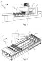
Figure 1 shows a perspective view of the working center that implements the method for determining the position of mobile devices in a working plane, according to the present invention; -
Figure 2 shows a top-down view of the working plane of the working center shown infigure 1 ; -
Figure 3 shows a schematic representation of a mobile device set-up of the working plane shown infigure 2 ; -
Figure 3a shows a schematic view of a representation of the working plane of the working center; -
Figure 4 shows a schematic representation of a further mobile device set-up of the working plane shown infigure 2 ; -
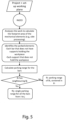
Figure 5 shows a first flowchart of the method for determining the position of mobile devices in a working plane, according to the present invention; -
Figure 6 shows a second flowchart of the method for determining the position of mobile devices in a working plane, according to the present invention; and -
Figure 7 shows a third flowchart of the method for determining the position of mobile devices in a working plane, according to the present invention. - In the various figures similar parts will be indicated with same numerical references.
- With reference to
figures 1 and 2 , there is shown a working center C for processing panels W made of wood, ceramics, plastics, glass, fiberglass and similar, which implements the method for determining the position of mobile devices in a working plane, object of this invention, which essentially comprises abase 1, through which this working center C rests on the ground, a workingplane 2, for the support of the panels W to be processed, amachining unit 3, equipped with amachining head 32 arranged on acrossbar 31, saidmachining head 32 supporting machining tools of the panels W and a logic control unit U. - Said logic control unit U retains in a memory the configurations of the work table 2 necessary to carry out the work on the panels W to be processed and sends signals for the operation of the components of the working center C according to the different processes to be performed.
- The logic control unit U is equipped with programmable processing means, such as CPUs, FPGAs or similar, for executing a program that can reproduce the algorithm behind the method for determining the position of mobile devices in a working plane.
- The directions described below refer to a system of cartesian axes, as shown in
Figure 1 , comprising a first X axis, a second Y axis and a third Z axis. - With working
plane 2 configurations it is intended the exact arrangement of mobile devices in said workingplane 2. - Said logic control unit U shall comprise a module for receiving and transmitting in wireless mode.
- Said
base 1 has an elongated shape, whose main dimension extends mainly according to a direction of development parallel to the first axis n X. - Said working
plane 2 is coupled to saidbase 1 and also has an elongated shape, whose main dimension extends mainly according to a direction of development parallel to that first X axis. - Said working
plane 2 comprises a plurality of supportingbars 21a,b,...i,...n which are slidingly coupled to saidbase 1 through a first 22 and asecond guide 23, integral to saidbase 1. - Said plurality of supporting
bars 21a,b,... i... n can be operated manually, along said first 22 and second 23 guides of saidbase 1, according to the X axis. - Each supporting
bar 21i of said plurality of supportingbars 21a,b,... i... n is aligned in a direction parallel to said second Y-axis. - Said
crossbar 31 is slidingly coupled to saidbase 1 in a direction parallel to said first X-axis, and themachining head 32 is slidingly coupled to saidcrossbar 31 along a direction parallel to said second Y-axis. Said machininghead 32 can also be movable along a direction parallel to said third Z-axis. Said machininghead 32 can also rotate around one, two or three or more rotation axes. Said plurality of supportingbars 21a,b,... i... n is suitable for supporting panels W to be machined. - On each supporting
bar 21i there is slidingly mounted a plurality ofmobile devices 24aa,bb...ij...nn, such as suction cups or clamps, for locking the panels W to be processed, by means of vacuum systems, during the processing of the panel W by part saidmachining head 32. - Said plurality of
mobile devices 24aa,bb,... ij... nn can be operated manually, along the respective bars of said plurality of supportingbars 21a, b,...j,...n according to the Y axis. - Each supporting
bar 21i and eachmobile device 24ij comprise means of feedback to provide the operator with information on their correct movement. - Said means of feedback may be means for displaying, to provide visual information to the operator.
- Said means of feedback for the operator can also be acoustic or tactile, such as a vibrating means.
- Said visual means, acoustic or tactile receive the signals sent by said logical control unit U and provide visual, acoustic or tactile feedback to the operator.
- Each supporting
bar 21i and eachmobile devices 24ij comprise at least one sensor, not shown in the figure, capable of detecting respectively the position in the workingplane 2 and the position along the supportingbar 21i. - In addition, each supporting
bar 21i and eachmobile device 24ij comprise a wireless reception and transmission module for exchanging data with said control logic unit U. - Referring now to
figures 3-7 , starting from an initial configuration of said workingplane 2 and the program to be executed on a panel W, the positioning intervals R of all moving devices that are not involved in machining are calculated. - First of all, the working
plane 2 is discretized, or divided into squares or cells, then it is verified, for each cell, the potential collision between said machininghead 32 during the intended processing and themobile devices 21a,b,...i,...n; 24aa,bb,...ij,...nn that are not involved in the machining program, thus obtaining a collision matrix of the workingplane 
figure 3a . - In a preferred form of realization, each cell ij of said

- Subsequently, taking into account the initial configuration of the supporting
bars 21a,b,... i,... n andmobile devices 24aa,bb,..ij...nn in the workingplane 2, of the overall dimensions and trajectories of themachining head 32, which can also perform processes that require lateral access to the panel W to be processed and, above all, of the type of work to be carried out, according to the selected program, it is possible to determine a zone Z1 in which said workingunit 3 performs the processing and in which the supportingbars 21a, b,...i,...n andmobile devices 24aa,bb,... ij... nn are involved in the processing. - Referring in particular to
Figure 3 , zone Z1 will have boundary coordinates X1, X2 and Y1, Y2 along said first X and second Y axis, respectively, which correspond to cells of the collisionmatrix 
- Once the zone Z1 has been defined, the positioning intervals or positioning ranges R of all the supporting
bars 21a,b,...i,...n andmobile devices 24aa,bb,..ij...nn that are not involved in the processing are calculated,, so that they occupy a safety space free from processing, and so as not to excessively alter the initial configuration of the workingplane 2. - The positioning range R of the supporting
bars 21a,b,...i...n not involved in the machining is numerically calculated from thevalue 0, which coincides with the meeting point of a first side of the workingplane 2, parallel to said first axis X, and a second side of the working plane parallel to that second axis Y, up to the coordinate X1 of zone Z1 and from the coordinate X2 to the end of the workingplane 2 or up to the next bar, also taking into account the geometric dimensions of all the components involved. - In the specific example shown in
Figure 3 , the supporting bars involved in machining are thebars 212, 213e bar 212,mobile devices bar 213, andmobile devices bar 214. - Therefore, the 211 supporting bar have a positioning range R from 0 to X1.
- The positioning range R of a supporting
bar 21i not involved in the processing and that does not have neighboring bars has as its average value the position that said bar occupied in the initial configuration, so as not to excessively alter the configuration of the workingplane 2. - The positioning range R of a supporting bar 2i not involved in the processing which has neighboring bars not involved in the processing has instead a determined value, so as not to invade the space of the neighboring bars.
- For example, the positioning range R of
bar 215 will have a positioning range R from X2 up to the X-axis coordinate occupied bybar 216. - As for the position of
mobile devices 24aa,bb,...ij... nn the positioning range R is calculated for each bar. - For bars not involved in machining, the supports can occupy any position, conveniently the position of the initial configuration, for the bars involved in the processing, the supports not involved in the processing can occupy the space from the beginning of the bar to the first ordered Y1 of zone Z1 and from the second ordered Y2 of zone Z1 to the end of the bar.
- For example, mobile device 2446 can be moved to P"ij space, and
suction cups - With reference to
Figure 4 , for the area of workingplane 2 which in the initial configuration includes parked bars not involved in machining, the positioning range R is calculated from the second coordinate X2 of zone Z1 to the end of workingplane 2, or, if there is a nearby parking area, the positioning ranges R are added together. - As is evident from the description above, the method for determining the position of mobile devices in a working plane and the related work center allow to change the initial configuration of the working plane quickly and safely, positioning all mobile devices in specific positions.
- This invention has been described as illustrative, but not limitative purpose, according to its preferred embodiment, but it is understood that variations and/or modifications may be made by a skilled person without being outside the scope of protection, as defined by the attached claims.
Claims (9)
- Method for determining the position of mobile devices (21a,b,...i,...n; 24aa,bb,...ij,...nn) in a working center (C) for machining at least one workpiece (W), in particular a panel, wherein said working center (C) comprises a working plane (2), for supporting said at least one panel (W), comprising in turn mobile devices (21 a,b,...i,...n; 24aa,bb,..ij,...nn) capable to move in a first direction parallel to a first axis (X) and a second direction parallel to a second axis (Y) orthogonal to said first direction, a working unit (3) comprising at least one working head (32), said method comprising the following steps:a. acquiring a machining program, comprising the overall dimensions and/or the trajectories of said at least one working head (32) and the types of machining to be performed on said panel (W);b. acquiring the arrangement of the initial configuration of said mobile devices (21a,b,...i,...n; 24aa,bb,...ij,...nn) in said working plane (2);c. identifying a zone (Z1) on said working plane (2) in which a group of said mobile devices involved in said machining program is arranged (21a,b,...i,...n; 24aa,bb,...ij,...nn);d. identifying the remaining group of said mobile devices (21a,b,...i,...n; 24aa,bb,...ij,...nn) not involved in said machining program;e. calculating a positioning range (R) for each mobile device of said remaining group of said mobile devices (21a,b,...i,...n; 24aa,bb,..ij,...nn) along said first direction and/or along said second direction, with respect to said initial configuration, based on the dimensions of said machining zone (Z1).
- Method according to the preceding claim, characterized in that it comprises the following further steps:f. discretizing said working plane (2) into cells, in which each cell (ij) corresponds to an area of the surface of said working plane (2);
f.1. checking the potential collision in each cell (ij) between said working head (32), in the execution of said machining program, and said mobile devices (21a,b,...i,...n; 24aa,bb,...ij,...nn) not involved in said machining program as a function of the trajectory and/or the overall dimensions of said working head (32);f.2. determining, on the basis of said steps f. and f.1, a collision matrix (
- Method according to any one of the preceding claims 2 and 3, characterizedin that said cells (ij) are squared and equal, andin that the measurement of the side of said cells is 1 millimeter.
- Method according to any one of the preceding claims, wherein said mobile devices (21a,b,...i,...n; 24aa,bb,...ij,...nn) comprise supporting bars (21a,b,...i,...n) movable on said working plane (2) along said first direction and mobile coupling devices (24aa,bb,...ij,...nn) for said workpiece (W), in particular suction cups or clamps, slidingly coupled to said supporting bars (21a,b,...i,...n) and movable along said second direction, characterized in that said step e. of calculating a positioning range (R) comprises the following sub-steps:e.1. calculating the positioning range (R) of said supporting bars (21a,b,...i,...n) along said first direction;e.2. for each of said supporting bars (21a,b,...i,...n), calculating the positioning range (R) of said mobile devices (24aa,bb,..ij,...nn) along said second direction.
- Method according to any one of the preceding claims, wherein said mobile devices (21a,b,...i,...n; 24aa,bb,...ij,...nn) comprise supporting bars (21a,b,...i,...n) movable on said working plane (2) along said first direction and mobile coupling devices (24aa,bb,...ij,...nn) for said workpiece (W), in particular suction cups or clamps, slidingly coupled to said supporting bars (21a,b,...i,...n) and movable along said second direction, characterized in that it comprises the following step:
c.1. for each of said supporting bars (21a,b,...i,...n) arranged in said zone (Z1), calculating the positioning range (R) of said mobile coupling devices (24aa,bb,...ij,...nn), along said second direction. - Working center (C) for machining workpieces (W) in particular panels in wood, ceramic, plastic, glass, fiberglass, comprising:- a base (1) for supporting said working center (C);- a working unit (3) comprising at least one working head (32) which supports at least one tool;- a working plane (2), coupled to said base (1), for supporting said workpieces (W), comprising in turn- a plurality of supporting bars (21a,b,...,i,...n), slidingly coupled and manually movable by an operator along said base (1);- a plurality of mobile coupling devices (24aa,bb,...ij,...nn), for coupling said workpieces (W) to be machined, slidingly coupled and manually movable by an operator along respective supporting bars (21a,b,...,i,...n);- a logic control unit (U) for the operation of said working center (C), in which configurations of said working plane (2) for the machining of said workpieces are stored;said working center (C) being characterizedin that said logic control unit (U) is configured to carry out the steps of the positioning method according to any one of claims 1-5 and to associate indications for an operator to said calculated positioning range (R), for the arrangement of said plurality of supporting bars (21a,b,...,i,...n) and said plurality of mobile coupling devices (24aa,bb,...ij,...nn).
- Working center (C) according to the preceding claim, characterized in that said mobile devices of said plurality of mobile coupling devices (24aa,bb,...ij,...nn) are suction cups or clamps.
- A computer program comprising instructions which, when the program is executed by a computer, cause the computer to execute the positioning determination of the mobile devices (21a,b,...i,...n; 24aa,bb,..ij,...nn) in a working plane (2) method, according to any one of claims 1-5.
- A computer readable storage medium comprising instructions which, when executed by a computer, cause the computer to execute the steps of the positioning determination of the mobile devices (21a,b,..i,..n; 24aa,bb,..ij,...nn) in a working plane (2) method, according to any one of claims 1-5.
Applications Claiming Priority (1)
| Application Number | Priority Date | Filing Date | Title |
|---|---|---|---|
| IT102022000009287A IT202200009287A1 (en) | 2022-05-06 | 2022-05-06 | Method for determining the placement of mobile devices in a work plane and work center that implements this method. |
Publications (1)
| Publication Number | Publication Date |
|---|---|
| EP4273642A1 true EP4273642A1 (en) | 2023-11-08 |
Family
ID=82780837
Family Applications (1)
| Application Number | Title | Priority Date | Filing Date |
|---|---|---|---|
| EP23170589.8A Pending EP4273642A1 (en) | 2022-05-06 | 2023-04-28 | Method for determining the position of the mobile devices in a working plane and machining center implementing such method |
Country Status (2)
| Country | Link |
|---|---|
| EP (1) | EP4273642A1 (en) |
| IT (1) | IT202200009287A1 (en) |
Citations (5)
| Publication number | Priority date | Publication date | Assignee | Title |
|---|---|---|---|---|
| EP0507033B1 (en) * | 1991-04-05 | 1995-02-01 | Manuel Torres Martinez | Machine tool installation for supporting and machining workpieces |
| EP1872919A1 (en) * | 2006-06-26 | 2008-01-02 | SCM GROUP S.p.A. | Machining centre for machining panels made of wood or the like |
| JP2015073977A (en) * | 2013-10-11 | 2015-04-20 | 平田機工株式会社 | Processing system |
| DE202018100790U1 (en) * | 2017-08-08 | 2018-03-20 | Rierge, S.A. | Machine for the numerically controlled processing of boards of wood, plastic and similar materials, the kind that a nesting work system can use |
| EP3658345B1 (en) * | 2017-07-26 | 2021-07-07 | Biesse S.p.A. | Electronically-controlled apparatus for cutting and machining natural or synthetic stone plates or glass plates |
-
2022
- 2022-05-06 IT IT102022000009287A patent/IT202200009287A1/en unknown
-
2023
- 2023-04-28 EP EP23170589.8A patent/EP4273642A1/en active Pending
Patent Citations (5)
| Publication number | Priority date | Publication date | Assignee | Title |
|---|---|---|---|---|
| EP0507033B1 (en) * | 1991-04-05 | 1995-02-01 | Manuel Torres Martinez | Machine tool installation for supporting and machining workpieces |
| EP1872919A1 (en) * | 2006-06-26 | 2008-01-02 | SCM GROUP S.p.A. | Machining centre for machining panels made of wood or the like |
| JP2015073977A (en) * | 2013-10-11 | 2015-04-20 | 平田機工株式会社 | Processing system |
| EP3658345B1 (en) * | 2017-07-26 | 2021-07-07 | Biesse S.p.A. | Electronically-controlled apparatus for cutting and machining natural or synthetic stone plates or glass plates |
| DE202018100790U1 (en) * | 2017-08-08 | 2018-03-20 | Rierge, S.A. | Machine for the numerically controlled processing of boards of wood, plastic and similar materials, the kind that a nesting work system can use |
Also Published As
| Publication number | Publication date |
|---|---|
| IT202200009287A1 (en) | 2023-11-06 |
Similar Documents
| Publication | Publication Date | Title |
|---|---|---|
| CN104423322B (en) | The automatic setting device and automatic setting method of the tool offset value of lathe | |
| JP6370821B2 (en) | Robot programming device that teaches robot programs | |
| US20110295408A1 (en) | Process for positioning a workpiece | |
| US11703828B2 (en) | System and method for automated precision control of a computer numerical control (CNC) machine | |
| WO2017168727A1 (en) | Instrument for measuring workpiece, and machine tool | |
| JP2023044664A (en) | Method for measuring workpiece in machine tool | |
| US6480757B1 (en) | Method of locating a workpiece on a computer numeric controlled machining system | |
| EP0957417B1 (en) | Work form-measuring method and device, and coordinate-measuring machine | |
| EP1247611B1 (en) | A multi-axis work centre, for multiple production, in particular for wood working | |
| SE459717B (en) | PLATEWORKING MACHINE AND A MEDIUM MACHINE IMPLEMENTABLE PROCEDURE | |
| CN109732399B (en) | A tool setting method, device, electronic device and storage medium for a numerically controlled machine tool | |
| CN110958930A (en) | Automatic attachment changing machine and boring machine equipped with the same | |
| US20020165637A1 (en) | Method for highly automated manufacture of metal parts | |
| JP3464307B2 (en) | Interference check method in NC lathe | |
| EP4273641A1 (en) | Method for determining the tolerances for placing coupling devices and working center implementing such method | |
| KR101393090B1 (en) | Workpiece setting methods for machining using machining center | |
| JP2010067101A (en) | Method of setting interference region of tool | |
| KR101751756B1 (en) | An elecrode setting method of CNC electric discharge machine | |
| KR102239220B1 (en) | Method for testing matrix type tool magazine | |
| KR101577572B1 (en) | Method, Device and Machining Center including thereof for automatically setting a workpiece origin | |
| KR20120103993A (en) | Method for safe space decision of tool and tool holer and apparatus thereof | |
| JP4549150B2 (en) | Interference area setting method for machine tools | |
| KR20070068797A (en) | Automated processing method of propeller | |
| JP2022025338A (en) | Teaching system | |
| CN115755759B (en) | Axial tool setting method of numerical control lathe |
Legal Events
| Date | Code | Title | Description |
|---|---|---|---|
| PUAI | Public reference made under article 153(3) epc to a published international application that has entered the european phase |
Free format text: ORIGINAL CODE: 0009012 |
|
| STAA | Information on the status of an ep patent application or granted ep patent |
Free format text: STATUS: THE APPLICATION HAS BEEN PUBLISHED |
|
| AK | Designated contracting states |
Kind code of ref document: A1 Designated state(s): AL AT BE BG CH CY CZ DE DK EE ES FI FR GB GR HR HU IE IS IT LI LT LU LV MC ME MK MT NL NO PL PT RO RS SE SI SK SM TR |
|
| STAA | Information on the status of an ep patent application or granted ep patent |
Free format text: STATUS: REQUEST FOR EXAMINATION WAS MADE |
|
| 17P | Request for examination filed |
Effective date: 20240321 |
|
| RBV | Designated contracting states (corrected) |
Designated state(s): AL AT BE BG CH CY CZ DE DK EE ES FI FR GB GR HR HU IE IS IT LI LT LU LV MC ME MK MT NL NO PL PT RO RS SE SI SK SM TR |
|
| STAA | Information on the status of an ep patent application or granted ep patent |
Free format text: STATUS: EXAMINATION IS IN PROGRESS |
|
| 17Q | First examination report despatched |
Effective date: 20250819 |