EP4272856A1 - Artificial lung and method for manufacturing artificial lung - Google Patents
Artificial lung and method for manufacturing artificial lung Download PDFInfo
- Publication number
- EP4272856A1 EP4272856A1 EP22749650.2A EP22749650A EP4272856A1 EP 4272856 A1 EP4272856 A1 EP 4272856A1 EP 22749650 A EP22749650 A EP 22749650A EP 4272856 A1 EP4272856 A1 EP 4272856A1
- Authority
- EP
- European Patent Office
- Prior art keywords
- outer tube
- hollow fiber
- anchor structure
- sealing material
- oxygenator
- Prior art date
- Legal status (The legal status is an assumption and is not a legal conclusion. Google has not performed a legal analysis and makes no representation as to the accuracy of the status listed.)
- Pending
Links
- 238000000034 method Methods 0.000 title claims description 24
- 238000004519 manufacturing process Methods 0.000 title claims description 18
- 210000004072 lung Anatomy 0.000 title description 3
- 239000012510 hollow fiber Substances 0.000 claims abstract description 66
- 239000003566 sealing material Substances 0.000 claims abstract description 65
- 230000002093 peripheral effect Effects 0.000 claims abstract description 40
- 239000012528 membrane Substances 0.000 claims abstract description 32
- 238000007789 sealing Methods 0.000 claims abstract description 29
- 238000005520 cutting process Methods 0.000 claims abstract description 15
- 239000008280 blood Substances 0.000 description 31
- 210000004369 blood Anatomy 0.000 description 31
- 239000007789 gas Substances 0.000 description 27
- CURLTUGMZLYLDI-UHFFFAOYSA-N Carbon dioxide Chemical compound O=C=O CURLTUGMZLYLDI-UHFFFAOYSA-N 0.000 description 12
- 230000004308 accommodation Effects 0.000 description 10
- 239000000463 material Substances 0.000 description 9
- 238000004382 potting Methods 0.000 description 9
- QVGXLLKOCUKJST-UHFFFAOYSA-N atomic oxygen Chemical compound [O] QVGXLLKOCUKJST-UHFFFAOYSA-N 0.000 description 7
- 229910052760 oxygen Inorganic materials 0.000 description 7
- 239000001301 oxygen Substances 0.000 description 7
- 230000017531 blood circulation Effects 0.000 description 6
- 229910002092 carbon dioxide Inorganic materials 0.000 description 6
- 239000001569 carbon dioxide Substances 0.000 description 6
- 125000006850 spacer group Chemical group 0.000 description 5
- 230000000052 comparative effect Effects 0.000 description 4
- 238000010586 diagram Methods 0.000 description 4
- 238000005192 partition Methods 0.000 description 4
- 238000000926 separation method Methods 0.000 description 3
- 239000000853 adhesive Substances 0.000 description 2
- 230000001070 adhesive effect Effects 0.000 description 2
- 230000004087 circulation Effects 0.000 description 2
- 230000000694 effects Effects 0.000 description 2
- 239000007788 liquid Substances 0.000 description 2
- 239000011347 resin Substances 0.000 description 2
- 229920005989 resin Polymers 0.000 description 2
- 229920002803 thermoplastic polyurethane Polymers 0.000 description 2
- 208000019901 Anxiety disease Diseases 0.000 description 1
- 230000001154 acute effect Effects 0.000 description 1
- 230000036506 anxiety Effects 0.000 description 1
- 238000007675 cardiac surgery Methods 0.000 description 1
- 230000008602 contraction Effects 0.000 description 1
- 238000007599 discharging Methods 0.000 description 1
- 208000019622 heart disease Diseases 0.000 description 1
- 238000001746 injection moulding Methods 0.000 description 1
- 238000012986 modification Methods 0.000 description 1
- 230000004048 modification Effects 0.000 description 1
- 238000000465 moulding Methods 0.000 description 1
- 238000001356 surgical procedure Methods 0.000 description 1
Images


Classifications
-
- B—PERFORMING OPERATIONS; TRANSPORTING
- B01—PHYSICAL OR CHEMICAL PROCESSES OR APPARATUS IN GENERAL
- B01D—SEPARATION
- B01D63/00—Apparatus in general for separation processes using semi-permeable membranes
- B01D63/02—Hollow fibre modules
- B01D63/021—Manufacturing thereof
-
- A—HUMAN NECESSITIES
- A61—MEDICAL OR VETERINARY SCIENCE; HYGIENE
- A61M—DEVICES FOR INTRODUCING MEDIA INTO, OR ONTO, THE BODY; DEVICES FOR TRANSDUCING BODY MEDIA OR FOR TAKING MEDIA FROM THE BODY; DEVICES FOR PRODUCING OR ENDING SLEEP OR STUPOR
- A61M1/00—Suction or pumping devices for medical purposes; Devices for carrying-off, for treatment of, or for carrying-over, body-liquids; Drainage systems
- A61M1/14—Dialysis systems; Artificial kidneys; Blood oxygenators ; Reciprocating systems for treatment of body fluids, e.g. single needle systems for hemofiltration or pheresis
- A61M1/16—Dialysis systems; Artificial kidneys; Blood oxygenators ; Reciprocating systems for treatment of body fluids, e.g. single needle systems for hemofiltration or pheresis with membranes
- A61M1/1621—Constructional aspects thereof
- A61M1/1629—Constructional aspects thereof with integral heat exchanger
-
- A—HUMAN NECESSITIES
- A61—MEDICAL OR VETERINARY SCIENCE; HYGIENE
- A61M—DEVICES FOR INTRODUCING MEDIA INTO, OR ONTO, THE BODY; DEVICES FOR TRANSDUCING BODY MEDIA OR FOR TAKING MEDIA FROM THE BODY; DEVICES FOR PRODUCING OR ENDING SLEEP OR STUPOR
- A61M1/00—Suction or pumping devices for medical purposes; Devices for carrying-off, for treatment of, or for carrying-over, body-liquids; Drainage systems
- A61M1/14—Dialysis systems; Artificial kidneys; Blood oxygenators ; Reciprocating systems for treatment of body fluids, e.g. single needle systems for hemofiltration or pheresis
- A61M1/16—Dialysis systems; Artificial kidneys; Blood oxygenators ; Reciprocating systems for treatment of body fluids, e.g. single needle systems for hemofiltration or pheresis with membranes
- A61M1/1698—Blood oxygenators with or without heat-exchangers
-
- A—HUMAN NECESSITIES
- A61—MEDICAL OR VETERINARY SCIENCE; HYGIENE
- A61M—DEVICES FOR INTRODUCING MEDIA INTO, OR ONTO, THE BODY; DEVICES FOR TRANSDUCING BODY MEDIA OR FOR TAKING MEDIA FROM THE BODY; DEVICES FOR PRODUCING OR ENDING SLEEP OR STUPOR
- A61M1/00—Suction or pumping devices for medical purposes; Devices for carrying-off, for treatment of, or for carrying-over, body-liquids; Drainage systems
- A61M1/36—Other treatment of blood in a by-pass of the natural circulatory system, e.g. temperature adaptation, irradiation ; Extra-corporeal blood circuits
- A61M1/3621—Extra-corporeal blood circuits
- A61M1/3623—Means for actively controlling temperature of blood
-
- B—PERFORMING OPERATIONS; TRANSPORTING
- B01—PHYSICAL OR CHEMICAL PROCESSES OR APPARATUS IN GENERAL
- B01D—SEPARATION
- B01D19/00—Degasification of liquids
- B01D19/0031—Degasification of liquids by filtration
-
- B—PERFORMING OPERATIONS; TRANSPORTING
- B01—PHYSICAL OR CHEMICAL PROCESSES OR APPARATUS IN GENERAL
- B01D—SEPARATION
- B01D63/00—Apparatus in general for separation processes using semi-permeable membranes
- B01D63/02—Hollow fibre modules
-
- B—PERFORMING OPERATIONS; TRANSPORTING
- B01—PHYSICAL OR CHEMICAL PROCESSES OR APPARATUS IN GENERAL
- B01D—SEPARATION
- B01D63/00—Apparatus in general for separation processes using semi-permeable membranes
- B01D63/02—Hollow fibre modules
- B01D63/021—Manufacturing thereof
- B01D63/022—Encapsulating hollow fibres
- B01D63/0222—Encapsulating hollow fibres using centrifugal forces
-
- A—HUMAN NECESSITIES
- A61—MEDICAL OR VETERINARY SCIENCE; HYGIENE
- A61M—DEVICES FOR INTRODUCING MEDIA INTO, OR ONTO, THE BODY; DEVICES FOR TRANSDUCING BODY MEDIA OR FOR TAKING MEDIA FROM THE BODY; DEVICES FOR PRODUCING OR ENDING SLEEP OR STUPOR
- A61M2207/00—Methods of manufacture, assembly or production
-
- B—PERFORMING OPERATIONS; TRANSPORTING
- B01—PHYSICAL OR CHEMICAL PROCESSES OR APPARATUS IN GENERAL
- B01D—SEPARATION
- B01D2313/00—Details relating to membrane modules or apparatus
- B01D2313/04—Specific sealing means
-
- B—PERFORMING OPERATIONS; TRANSPORTING
- B01—PHYSICAL OR CHEMICAL PROCESSES OR APPARATUS IN GENERAL
- B01D—SEPARATION
- B01D2313/00—Details relating to membrane modules or apparatus
- B01D2313/20—Specific housing
-
- B—PERFORMING OPERATIONS; TRANSPORTING
- B01—PHYSICAL OR CHEMICAL PROCESSES OR APPARATUS IN GENERAL
- B01D—SEPARATION
- B01D2313/00—Details relating to membrane modules or apparatus
- B01D2313/22—Cooling or heating elements
- B01D2313/221—Heat exchangers
Definitions
- the present invention relates to an oxygenator for removing carbon dioxide in blood through a hollow fiber membrane and adding oxygen to the blood, and a method for manufacturing the oxygenator.
- a hollow fiber membrane oxygenator using a porous membrane is generally and widely used as an extracorporeal circulation device or an artificial heart-lung machine for assisting circulation in open-heart surgery or the like of heart disease.
- the membrane oxygenator mainly uses a hollow fiber membrane, and performs gas exchange and heat exchange of blood through the hollow fiber membrane.
- the hollow fiber membrane is wound around a cylindrical member and accommodated in a cylindrical outer tube. Both ends of the outer tube are filled with a potting material such as a urethane resin in order to seal an internal space that accommodates the hollow fiber membrane (for example, JP 2002-35116 A ).
- a potting material such as a urethane resin
- a liquid potting material (hereinafter also referred to as a sealing material) is poured into a gap between the outer tube and the hollow fiber membrane under the centrifugal action. Thereafter, the liquid sealing material is cured to form a sealing structure. Since the sealing material contracts during a manufacturing process, a groove-shaped anchor structure having protrusions and recesses is provided inside the outer tube in order to prevent separation between the outer tube and the sealing material.
- bubbles are not sufficiently removed due to the anchor structure, and large bubbles may remain in the sealing material near the anchor structure.
- Such bubbles in the sealing material do not affect sealing performance, but are visible in appearance, and thus may give a user a sense of anxiety.
- an object of the present invention is to provide an oxygenator capable of preventing bubbles from remaining in a sealing material and a method for manufacturing the oxygenator.
- an oxygenator including: a hollow fiber module having a plurality of hollow fiber membranes; an outer tube that is cylindrical and that accommodates the hollow fiber module; and a sealing structure that is provided at an end of the outer tube and seals a gap between an outer peripheral portion of the hollow fiber module and an inner peripheral portion of the outer tube, wherein the sealing structure includes an anchor structure that is formed on the outer tube on an inner peripheral side near the end and that has a groove recessed in an axial direction of the outer tube, a cutout portion formed by cutting out the groove of the anchor structure on the inner peripheral side, and a sealing material with which the anchor structure and the gap are filled.
- Another aspect provides a method for manufacturing an oxygenator that includes a hollow fiber module having a plurality of hollow fiber membranes, an outer tube that is cylindrical and that accommodates the hollow fiber module, and a sealing structure that is provided at an end of the outer tube and that seals a gap between an outer peripheral portion of the hollow fiber module and an inner peripheral portion of the outer tube, the sealing structure including an anchor structure that is formed on the outer tube on an inner peripheral side near the end and that has a groove recessed in an axial direction of the outer tube, a cutout portion formed by cutting out the groove of the anchor structure on the inner peripheral side, and a sealing material with which the anchor structure and the gap are filled, the method including: accommodating the hollow fiber module into the outer tube; and filling the groove and the gap between the outer tube and the hollow fiber module with the sealing material while applying a centrifugal force in the axial direction of the outer tube.
- the oxygenator and the method for manufacturing the oxygenator according to the above aspects can prevent bubbles from remaining in the sealing material.
- an oxygenator 10 is a medical device that temporarily functions as a lung during an operation such as cardiac surgery of a human body.
- the oxygenator 10 is a device for adjusting a blood temperature, removing carbon dioxide in the blood, and supplying oxygen into the blood in extracorporeal blood circulation.
- the oxygenator 10 includes a housing 12, a heat exchanger 14 which is an inner tube portion 13, a gas exchanger 16 which is an outer tube portion 15, and an intermediate spacer 18.
- the heat exchanger 14 and the gas exchanger 16 include a plurality of hollow fiber membranes and are joined with the intermediate spacer 18 therebetween.
- the heat exchanger 14, the intermediate spacer 18, and the gas exchanger 16 which are wound around a core 20 constitute a hollow fiber module 19.
- the housing 12 includes the core 20 constituting a central portion of the oxygenator 10, an outer tube 22 provided on an outer peripheral side of the core 20, a first cover member 24a attached to one end of the core 20 and one end of the outer tube 22, and a second cover member 24b attached to the other end of the core 20 and the other end of the outer tube 22.
- the core 20, the outer tube 22, the first cover member 24a, and the second cover member 24b form an accommodation space S for accommodating the cylindrical heat exchanger 14 and the cylindrical gas exchanger 16.
- the accommodation space S functions as a blood flow path 28.
- Each of the core 20, the outer tube 22, the first cover member 24a, and the second cover member 24b is formed of a hard resin.
- the core 20 includes a first core portion 30 constituting one end of the core 20 and a second core portion 32 constituting the other end of the core 20.
- the first core portion 30 and the second core portion 32 are coupled to each other by a plurality of connecting portions 34.
- the first core portion 30 has a blood inflow portion 36 to which a tube (not illustrated) can be connected at one end, and an annular wall 38 extending radially outward from the blood inflow portion 36.
- the outer end of the wall 38 is provided with a first support portion 40 for supporting the heat exchanger 14, and a first annular protrusion 42 protruding from the first support portion 40 to one side of the outer tube 22 in the axial direction (direction of arrow X1 in Fig. 1 ).
- the second core portion 32 is formed in a bottomed cylindrical shape, and includes a cylindrical portion 44 and a closing portion 46 provided at one end (end in the direction of arrow X1) of the cylindrical portion 44.
- the closing portion 46 is disposed so as to face the wall 38 with a gap therebetween.
- the gap between the closing portion 46 and the wall 38 functions as a blood introduction path 48 for guiding the blood flowing in through the blood inflow portion 36 into the accommodation space S.
- the outer surface of the cylindrical portion 44 is provided with a second support portion 50 for supporting the heat exchanger 14, and a second annular protrusion 52 protruding from the second support portion 50 to the other side of the outer tube 22 in the axial direction (direction of arrow X2 in Fig. 1 ).
- the second support portion 50 is located at the other end of the cylindrical portion 44.
- a first partition wall 62a annularly extends and protrudes in the axial direction from the inner surface of a first cover main body 56a toward the side where the heat exchanger 14 and the gas exchanger 16 are located.
- the protruding end of the first partition wall 62a is fixed by an adhesive 64a in a state of being inserted between one end of the heat exchanger 14 and one end of the gas exchanger 16.
- a first sealing structure 82a for sealing blood inside the accommodation space S is provided on one end side of the outer tube 22.
- the first sealing structure 82a prevents leakage of blood in the accommodation space S into a first gas flow path 60a.
- a second sealing structure 82b for sealing blood inside the accommodation space S is provided on the other end side of the outer tube 22.
- the second sealing structure 82b prevents leakage of blood in the accommodation space S into a second gas flow path 60b.
- the first sealing structure 82a includes a first anchor structure 84a having a groove-shaped recess provided on the inner peripheral side of the outer tube 22, and a first sealing material 86a with which a gap between the outer tube 22 and the gas exchanger 16 is filled.
- the second sealing structure 82b includes a second anchor structure 84b having a groove-shaped recess provided on the inner peripheral side of the outer tube 22, and a second sealing material 86b with which a gap between the outer tube 22 and the gas exchanger 16 is filled.
- the second anchor structure 84b of the second sealing structure 82b includes a groove formed in the outer tube 22 on the inner peripheral side in the vicinity of the other end.
- the second anchor structure 84b is formed over the entire circumferential area of the inner periphery of the cylindrical outer tube 22, and is formed in a circular shape when viewed in the axial direction.
- the groove constituting the second anchor structure 84b is constant in position of the outer tube 22 in the axial direction, and is separated from the other end of the outer tube 22 by a constant distance in the axial direction.
- the second anchor structure 84b has a bottom portion 84b1 constituting the bottom of the groove.
- An outer inclined surface 84b2 inclined so as to gradually increase in diameter as it extends to the end of the outer tube 22 is formed on the outer peripheral side of the bottom portion 84b1.
- An inner inclined surface 84b3 meeting the outer inclined surface 84b2 at an acute angle is formed on the inner peripheral side of the bottom portion 84b1.
- the bottom portion 84b1 is formed as a ridge portion where the outer inclined surface 84b2 and the inner inclined surface 84b3 meet.
- the second anchor structure 84b prevents separation of the second sealing material 86b due to thermal contraction.
- a cutout portion 88 formed by cutting out the groove constituting the second anchor structure 84b is formed in a part of the second anchor structure 84b in the circumferential direction.
- the cutout portion 88 is formed by cutting out a portion of a protrusion constituting the inner inclined surface 84b3 constituting the second anchor structure 84b.
- a bottom surface 88a of the cutout portion 88 is defined by a flat surface perpendicular to the axial direction of the outer tube 22.
- the bottom surface 88a is provided on the inner side in the axial direction than the bottom portion 84b1 of the second anchor structure 84b, and when a centrifugal force toward the inner side in the axial direction is applied, a potting material (sealing material 86) introduced into the second anchor structure 84b can be discharged.
- the bottom surface 88a is not limited to be perpendicular to the axial direction of the outer tube 22, and may be inclined with respect to the axial direction of the outer tube 22.
- the bottom surface 88a on the inner peripheral side may be inclined toward the inner side of the outer tube 22 as indicated by an imaginary line 88b in Fig. 6B from the viewpoint of the discharging efficiency of the sealing material 86 (potting material).
- a pair of cutout portions 88 is provided at positions facing each other across the central axis of the outer tube 22.
- the cutout portions are provided at the 0 o'clock position (upper end position) and the 6 o'clock position (lower end position).
- the number of cutout portions 88 to be formed is not limited to one pair (two), and may be three or more.
- the paired cutout portions 88 are preferably disposed at positions facing each other across the central axis of the outer tube 22.
- a gap between the outer tube 22 and the other end of the gas exchanger 16 is filled with the second sealing material 86b.
- the entire region of the second anchor structure 84b including the cutout portions 88 is filled with the second sealing material 86b.
- the other end of the second sealing material 86b has substantially the same height as the other end of the gas exchanger 16.
- a urethane resin or the like can be used, for example.
- the first anchor structure 84a is formed on one end side of the outer tube 22.
- the first anchor structure 84a is configured similarly to the second anchor structure 84b, and has the cutout portions 88 at the same positions in the circumferential direction.
- the first anchor structure 84a is filled with the first sealing material 86a.
- the first sealing material 86a is configured similarly to the second sealing material 86b.
- the first sealing material 86a and the second sealing material 86b are collectively referred to as a sealing material 86.
- a heat medium is supplied to a heat medium inflow portion 68 of the oxygenator 10, oxygen is supplied to a gas inflow portion 70, and blood from a human body is introduced into the blood inflow portion 36 through a centrifugal pump or a roller pump (not illustrated).
- the heat medium supplied from the heat medium inflow portion 68 is introduced into a lumen of a first hollow fiber membrane 14a of the heat exchanger 14 through a first heat medium flow path 58a.
- the heat medium exchanges heat with blood when passing through the lumen of the first hollow fiber membrane 14a.
- the heat medium having passed through the first hollow fiber membrane 14a is collected in a second heat medium flow path 58b and flows out of the oxygenator 10 through a heat medium outflow portion 76.
- Oxygen supplied from the gas inflow portion 70 is introduced into the lumen of a second hollow fiber membrane 16a of the gas exchanger 16 through the first gas flow path 60a. Oxygen diffuses to the blood side when passing through the lumen of the second hollow fiber membrane 16a.
- carbon dioxide in blood is discharged into the lumen of the second hollow fiber membrane 16a through the second hollow fiber membrane 16a. That is, gas exchange between oxygen and carbon dioxide is performed with blood through the second hollow fiber membrane 16a.
- Carbon dioxide in the lumen of the second hollow fiber membrane 16a is collected in the second gas flow path 60b and flows out to the outside through a gas outflow portion 78.
- the blood introduced from the blood inflow portion 36 is guided to the blood flow path 28 (accommodation space S) through the blood introduction path 48.
- the blood in the blood flow path 28 passes through clearances of the heat exchanger 14 toward the outside in the radial direction in the accommodation space S. As a result, heat is exchanged between the blood and the heat medium in the lumen of the first hollow fiber membrane 14a.
- the heat-exchanged blood flows radially outward in the accommodation space S through the intermediate spacer 18 and passes through the second hollow fiber membrane 16a of the gas exchanger 16.
- the blood performs gas exchange for absorbing oxygen that has passed through the second hollow fiber membrane 16a and releasing excessive carbon dioxide through the second hollow fiber membrane 16a.
- the blood subjected to the gas exchange flows in the blood flow path 28 in the circumferential direction, flows out of the oxygenator 10 through the blood outflow port 54, and returns to the human body.
- the hollow fiber module 19 is obtained that includes the heat exchanger 14, the intermediate spacer 18, and the gas exchanger 16 which are formed in order from the inner peripheral side as illustrated in Fig. 7 .
- a first cap member 92a, a first annular member 96a, a second cap member 92b, and a second annular member 96b in Fig. 7 are members used only for manufacturing the hollow fiber module 19, and are removed in a removal step described later.
- the outer tube 22 is formed.
- the outer tube 22 is integrally formed by various resin molding methods such as injection molding.
- the hollow fiber module 19 and the outer tube 22 are assembled as illustrated in Fig. 7 .
- the outer periphery of the gas exchanger 16 is covered by the outer tube 22.
- a cutting step is performed on the hollow fiber module 19.
- the heat exchanger 14 and the gas exchanger 16 are cut along a first cutting line Cl and a second cutting line C2 in Fig. 7 .
- a sealing step is performed as illustrated in Fig. 8 .
- the gap between the outer peripheral portion of the hollow fiber module 19 and the outer tube 22 is filled with the first sealing material 86a and the second sealing material 86b.
- the second sealing material 86b is disposed and fixed to a holding jig (not illustrated) such that the blood outflow port 54 of the outer tube 22 is located at the lower end and the prime auxiliary port 55 is located at the upper end. Therefore, the cutout portions 88 are disposed at the 0 o'clock position and the 6 o'clock position of the outer tube 22.
- the central axis of the outer tube 22 is oriented in a direction perpendicular to the rotation axis of the holding jig. Thereafter, a centrifugal force is applied in the axial direction (X1 direction) of the outer tube 22 by rotating the holding jig along the rotation axis.
- the second anchor structure 84b formed at the other end of the outer tube 22 varies in distance from the rotation center depending on the position in the circumferential direction as viewed from above the rotation center. As illustrated, the 0 o'clock position and the 6 o'clock position of the outer tube 22 are closest to the rotation center. On the other hand, the 3 o'clock position and the 9 o'clock position of the outer tube 22 are the farthest from the rotation center. The centrifugal force is larger in a region farther from the rotation center. Therefore, in the second anchor structure 84b, the centrifugal force is the largest at the 3 o'clock position and the 9 o'clock position and is the smallest at the 0 o'clock position and the 6 o'clock position.
- the second sealing material 86b (see Fig. 8 ) is introduced from the 3 o'clock position and the 9 o'clock position at which the centrifugal force is the largest as illustrated in Fig. 11A .
- the second anchor structure 84b is filled with the second sealing material 86b which spreads in the circumferential direction of the second anchor structure 84b under the action of the centrifugal force. Air in the second anchor structure 84b is discharged while being pushed out by the interface (interface with air) of the second sealing material 86b.
- the interface of the second sealing material 86b gradually advances from the 3 o'clock position and the 9 o'clock position toward the 0 o'clock position and the 6 o'clock position where the cutout portions 88 are provided. Accordingly, excess air is smoothly discharged from the second anchor structure 84b.
- the interface of the second sealing material 86b reaches the vicinity of the cutout portions 88 having the smallest centrifugal force in the second anchor structure 84b, and thus, the cutout portions 88 are filled with the second sealing material 86b without leaving bubbles, as illustrated in Fig. 11C .
- the second sealing material 86b is cured, and thus, the filling with the second sealing material 86b is completed.
- the filling with the first sealing material 86a is also performed in the same manner as the second sealing material 86b.
- the first cap member 92a, the first annular member 96a, the second cap member 92b, and the second annular member 96b are removed from the hollow fiber module 19.
- gaps are formed at one end and the other end of the heat exchanger 14 and the gas exchanger 16.
- the first cover member 24a and the second cover member 24b are attached to one end and the other end of the outer tube 22 and the core 20, respectively, and are fixed with the adhesives 64a and 64b.
- the protruding end of the first partition wall 62a is inserted into a first gap
- the protruding end of a second partition wall 62b is inserted into a second gap.
- Example 1 (Comparative Example) illustrated in Fig. 12 , the oxygenator 10 was filled with the second sealing material 86b without having the cutout portions 88 provided in the second anchor structure 84b.
- Examination Example 1 (Comparative Example) bubbles remained in a state of being connected over a wide range in the circumferential direction of the second anchor structure 84b around the 0 o'clock position and the 6 o'clock position.
- the oxygenator 10 according to the present embodiment has the following effects.
- An oxygenator 10 includes: a hollow fiber module 19 having a plurality of hollow fiber membranes (for example, first hollow fiber membrane 14a and second hollow fiber membrane 16a); an outer tube 22 that is cylindrical and that accommodates the hollow fiber module 19; and a sealing structure (for example, first sealing structure 82a or second sealing structure 82b) that is provided at an end of the outer tube 22 and seals a gap between an outer peripheral portion of the hollow fiber module 19 and an inner peripheral portion of the outer tube 22, wherein the sealing structure includes an anchor structure (for example, first anchor structure 84a or second anchor structure 84b) that is formed on the outer tube 22 on an inner peripheral side near the end and that has a groove recessed in an axial direction of the outer tube 22, a cutout portion 88 formed by cutting out the groove of the anchor structure on the inner peripheral side, and a sealing material 86 (potting material) with which the anchor structure and the gap are filled.
- an anchor structure for example, first anchor structure 84a or second anchor structure 84b
- the cutout portion 88 may include a plurality of the cutout portions 88 which may be provided at positions facing each other in the circumferential direction of the anchor structure.
- the groove of the anchor structure may be formed in the outer tube 22 on the inner peripheral side, and the cutout portion 88 may be formed by cutting out the groove on the inner peripheral side.
- the anchor structure is formed on the inner peripheral side of the outer tube 22, whereby separation of the sealing material 86 can be prevented, and bubbles remaining in the anchor structure can be reduced.
- the cutout portion 88 may be provided at a position where a centrifugal force is the smallest when the centrifugal force is applied in the axial direction of the outer tube 22. With this configuration, the cutout portion 88 is disposed at a last region of the anchor structure where the interface of the sealing material 86 reaches, whereby air pushed out by the interface of the sealing material 86 is smoothly discharged through the cutout portion 88.
- the present embodiment provides a method for manufacturing an oxygenator 10 that includes a hollow fiber module 19 having a hollow fiber membrane that is wound, an outer tube 22 that is cylindrical and that accommodates the hollow fiber module 19, and a sealing structure that seals a gap between an outer peripheral portion of the hollow fiber module 19 and an inner peripheral portion of the outer tube 22, the sealing structure including an anchor structure that is formed at the end of the outer tube 22 and that has a groove formed over an entire circumference, a cutout portion 88 formed by cutting out a part of the groove of the anchor structure in a circumferential direction, and a sealing material 86 with which the anchor structure and the gap are filled, the method including: accommodating the hollow fiber module 19 into the outer tube 22; and filling the anchor structure and the gap between the outer tube 22 and the hollow fiber module 19 with the sealing material 86 while applying a centrifugal force in the axial direction of the outer tube 22.
- the sealing material 86 may be introduced with the cutout portion 88 being provided at a region where the centrifugal force is the smallest.
- the cutout portion 88 is disposed at the last region where the interface of the sealing material 86 reaches, whereby air pushed out by the interface of the sealing material 86 is smoothly discharged through the cutout portion 88.
- the sealing material 86 may be introduced from a region where the centrifugal force acting on the sealing material 86 is the largest. According to this method, the interface of the sealing material 86 advances from the region where the centrifugal force is the largest toward the region where the centrifugal force is the smallest, whereby air in the anchor structure can be smoothly discharged from the cutout portion 88.
- an outer tube 22A of the present embodiment is provided with a first anchor structure 84a and a second anchor structure 84b which meander in the axial direction.
- the first anchor structure 84a and the second anchor structure 84b meander so as to be closest to the end of the outer tube 22A at the 0 o'clock position and the 6 o'clock position and farthest from the end of the outer tube 22A at the 3 o'clock position and the 9 o'clock position.
- cutout portions 88 are formed at positions closest to the end of the outer tube 22A.
- the first anchor structure 84a and the second anchor structure 84b meander such that the regions where the cutout portions 88 are formed are located closest to the rotation center when the centrifugal force is applied, regardless of how the outer tube 22A is disposed. Therefore, during the process of introducing the first sealing material 86a or the second sealing material 86b, the cutout portions 88 are always disposed in the region having the smallest centrifugal force regardless of the orientation of the outer tube 22A in the circumferential direction. Accordingly, the same effects as those of the outer tube 22 of the first embodiment (see Fig. 3 and the like) can be obtained by the outer tube 22A of the present embodiment.
Landscapes
- Health & Medical Sciences (AREA)
- Heart & Thoracic Surgery (AREA)
- Engineering & Computer Science (AREA)
- Urology & Nephrology (AREA)
- Emergency Medicine (AREA)
- Vascular Medicine (AREA)
- Chemical & Material Sciences (AREA)
- Chemical Kinetics & Catalysis (AREA)
- Anesthesiology (AREA)
- Biomedical Technology (AREA)
- Hematology (AREA)
- Life Sciences & Earth Sciences (AREA)
- Animal Behavior & Ethology (AREA)
- General Health & Medical Sciences (AREA)
- Public Health (AREA)
- Veterinary Medicine (AREA)
- Manufacturing & Machinery (AREA)
- Cardiology (AREA)
- External Artificial Organs (AREA)
Abstract
Description
- The present invention relates to an oxygenator for removing carbon dioxide in blood through a hollow fiber membrane and adding oxygen to the blood, and a method for manufacturing the oxygenator.
- A hollow fiber membrane oxygenator using a porous membrane is generally and widely used as an extracorporeal circulation device or an artificial heart-lung machine for assisting circulation in open-heart surgery or the like of heart disease. The membrane oxygenator mainly uses a hollow fiber membrane, and performs gas exchange and heat exchange of blood through the hollow fiber membrane.
- In the oxygenator, the hollow fiber membrane is wound around a cylindrical member and accommodated in a cylindrical outer tube. Both ends of the outer tube are filled with a potting material such as a urethane resin in order to seal an internal space that accommodates the hollow fiber membrane (for example,
JP 2002-35116 A - Regarding the potting material, a liquid potting material (hereinafter also referred to as a sealing material) is poured into a gap between the outer tube and the hollow fiber membrane under the centrifugal action. Thereafter, the liquid sealing material is cured to form a sealing structure. Since the sealing material contracts during a manufacturing process, a groove-shaped anchor structure having protrusions and recesses is provided inside the outer tube in order to prevent separation between the outer tube and the sealing material.
- However, bubbles are not sufficiently removed due to the anchor structure, and large bubbles may remain in the sealing material near the anchor structure. Such bubbles in the sealing material do not affect sealing performance, but are visible in appearance, and thus may give a user a sense of anxiety.
- In view of this, an object of the present invention is to provide an oxygenator capable of preventing bubbles from remaining in a sealing material and a method for manufacturing the oxygenator.
- One aspect of the present invention provides an oxygenator including: a hollow fiber module having a plurality of hollow fiber membranes; an outer tube that is cylindrical and that accommodates the hollow fiber module; and a sealing structure that is provided at an end of the outer tube and seals a gap between an outer peripheral portion of the hollow fiber module and an inner peripheral portion of the outer tube, wherein the sealing structure includes an anchor structure that is formed on the outer tube on an inner peripheral side near the end and that has a groove recessed in an axial direction of the outer tube, a cutout portion formed by cutting out the groove of the anchor structure on the inner peripheral side, and a sealing material with which the anchor structure and the gap are filled.
- Another aspect provides a method for manufacturing an oxygenator that includes a hollow fiber module having a plurality of hollow fiber membranes, an outer tube that is cylindrical and that accommodates the hollow fiber module, and a sealing structure that is provided at an end of the outer tube and that seals a gap between an outer peripheral portion of the hollow fiber module and an inner peripheral portion of the outer tube, the sealing structure including an anchor structure that is formed on the outer tube on an inner peripheral side near the end and that has a groove recessed in an axial direction of the outer tube, a cutout portion formed by cutting out the groove of the anchor structure on the inner peripheral side, and a sealing material with which the anchor structure and the gap are filled, the method including: accommodating the hollow fiber module into the outer tube; and filling the groove and the gap between the outer tube and the hollow fiber module with the sealing material while applying a centrifugal force in the axial direction of the outer tube.
- The oxygenator and the method for manufacturing the oxygenator according to the above aspects can prevent bubbles from remaining in the sealing material.
-
-
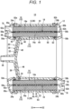
Fig. 1 is a longitudinal sectional view of an oxygenator according to a first embodiment. -
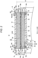
Fig. 2 is an enlarged cross-sectional view of the vicinity of the outer periphery of the oxygenator illustrated inFig. 1 . -
Fig. 3 is a perspective view of an outer tube inFig. 1 . -
Fig. 4 is a front view of the outer tube inFig. 1 . -
Fig. 5 is an enlarged cross-sectional view of an anchor structure inFig. 4 . -
Fig. 6A is an enlarged perspective view illustrating a cutout portion of the anchor structure, andFig. 6B is a sectional perspective view of the cutout portion. -
Fig. 7 is a cross-sectional view illustrating a step for accommodating a hollow fiber module in the outer tube in a method for manufacturing the oxygenator illustrated inFig. 1 . -
Fig. 8 is a cross-sectional view illustrating a step for filling a gap between the outer tube and the hollow fiber module with a potting material in the method for manufacturing the oxygenator illustrated inFig. 1 . -
Fig. 9 is an explanatory diagram illustrating a direction in which a centrifugal force is applied in the step for filling the gap with the potting material. -
Fig. 10 is an explanatory diagram illustrating a distance relationship between the anchor structure of the outer tube and a rotation center. -
Figs. 11A to 11C are explanatory diagrams illustrating the movement of the potting material and bubbles at the end of the outer tube in the order of the steps. -
Fig. 12 is a photograph of the vicinity of an anchor structure of an oxygenator according to Examination Example 1 (Comparative Example). -
Fig. 13 is a photograph of the vicinity of an anchor structure of an oxygenator according to Examination Example 2 (first embodiment). -
Fig. 14 is a schematic diagram of an outer tube according to a second embodiment. - Preferred embodiments of an oxygenator and a method for manufacturing the oxygenator will be described below in detail with reference to the accompanying drawings.
- As illustrated in
Fig. 1 , anoxygenator 10 according to the present embodiment is a medical device that temporarily functions as a lung during an operation such as cardiac surgery of a human body. Specifically, theoxygenator 10 is a device for adjusting a blood temperature, removing carbon dioxide in the blood, and supplying oxygen into the blood in extracorporeal blood circulation. - As illustrated in
Figs. 1 and2 , theoxygenator 10 includes ahousing 12, aheat exchanger 14 which is aninner tube portion 13, agas exchanger 16 which is anouter tube portion 15, and anintermediate spacer 18. Theheat exchanger 14 and thegas exchanger 16 include a plurality of hollow fiber membranes and are joined with theintermediate spacer 18 therebetween. Theheat exchanger 14, theintermediate spacer 18, and thegas exchanger 16 which are wound around acore 20 constitute ahollow fiber module 19. - In
Fig. 1 , thehousing 12 includes thecore 20 constituting a central portion of theoxygenator 10, anouter tube 22 provided on an outer peripheral side of thecore 20, afirst cover member 24a attached to one end of thecore 20 and one end of theouter tube 22, and asecond cover member 24b attached to the other end of thecore 20 and the other end of theouter tube 22. - The
core 20, theouter tube 22, thefirst cover member 24a, and thesecond cover member 24b form an accommodation space S for accommodating thecylindrical heat exchanger 14 and thecylindrical gas exchanger 16. The accommodation space S functions as ablood flow path 28. Each of thecore 20, theouter tube 22, thefirst cover member 24a, and thesecond cover member 24b is formed of a hard resin. - The
core 20 includes afirst core portion 30 constituting one end of thecore 20 and asecond core portion 32 constituting the other end of thecore 20. Thefirst core portion 30 and thesecond core portion 32 are coupled to each other by a plurality of connectingportions 34. - The
first core portion 30 has ablood inflow portion 36 to which a tube (not illustrated) can be connected at one end, and anannular wall 38 extending radially outward from theblood inflow portion 36. The outer end of thewall 38 is provided with afirst support portion 40 for supporting theheat exchanger 14, and a firstannular protrusion 42 protruding from thefirst support portion 40 to one side of theouter tube 22 in the axial direction (direction of arrow X1 inFig. 1 ). - The
second core portion 32 is formed in a bottomed cylindrical shape, and includes acylindrical portion 44 and aclosing portion 46 provided at one end (end in the direction of arrow X1) of thecylindrical portion 44. Theclosing portion 46 is disposed so as to face thewall 38 with a gap therebetween. The gap between theclosing portion 46 and thewall 38 functions as ablood introduction path 48 for guiding the blood flowing in through theblood inflow portion 36 into the accommodation space S. The outer surface of thecylindrical portion 44 is provided with asecond support portion 50 for supporting theheat exchanger 14, and a secondannular protrusion 52 protruding from thesecond support portion 50 to the other side of theouter tube 22 in the axial direction (direction of arrow X2 inFig. 1 ). Thesecond support portion 50 is located at the other end of thecylindrical portion 44. - As illustrated in
Fig. 2 , afirst partition wall 62a annularly extends and protrudes in the axial direction from the inner surface of a first covermain body 56a toward the side where theheat exchanger 14 and thegas exchanger 16 are located. The protruding end of thefirst partition wall 62a is fixed by an adhesive 64a in a state of being inserted between one end of theheat exchanger 14 and one end of thegas exchanger 16. - As illustrated in
Fig. 2 , afirst sealing structure 82a for sealing blood inside the accommodation space S is provided on one end side of theouter tube 22. Thefirst sealing structure 82a prevents leakage of blood in the accommodation space S into a firstgas flow path 60a. In addition, asecond sealing structure 82b for sealing blood inside the accommodation space S is provided on the other end side of theouter tube 22. Thesecond sealing structure 82b prevents leakage of blood in the accommodation space S into a secondgas flow path 60b. - The
first sealing structure 82a includes afirst anchor structure 84a having a groove-shaped recess provided on the inner peripheral side of theouter tube 22, and afirst sealing material 86a with which a gap between theouter tube 22 and thegas exchanger 16 is filled. In addition, thesecond sealing structure 82b includes asecond anchor structure 84b having a groove-shaped recess provided on the inner peripheral side of theouter tube 22, and asecond sealing material 86b with which a gap between theouter tube 22 and thegas exchanger 16 is filled. - As illustrated in
Fig. 3 , thesecond anchor structure 84b of thesecond sealing structure 82b includes a groove formed in theouter tube 22 on the inner peripheral side in the vicinity of the other end. As illustrated inFig. 4 , thesecond anchor structure 84b is formed over the entire circumferential area of the inner periphery of the cylindricalouter tube 22, and is formed in a circular shape when viewed in the axial direction. The groove constituting thesecond anchor structure 84b is constant in position of theouter tube 22 in the axial direction, and is separated from the other end of theouter tube 22 by a constant distance in the axial direction. - As illustrated in
Fig. 5 , thesecond anchor structure 84b has a bottom portion 84b1 constituting the bottom of the groove. An outer inclined surface 84b2 inclined so as to gradually increase in diameter as it extends to the end of theouter tube 22 is formed on the outer peripheral side of the bottom portion 84b1. An inner inclined surface 84b3 meeting the outer inclined surface 84b2 at an acute angle is formed on the inner peripheral side of the bottom portion 84b1. The bottom portion 84b1 is formed as a ridge portion where the outer inclined surface 84b2 and the inner inclined surface 84b3 meet. Thesecond anchor structure 84b prevents separation of thesecond sealing material 86b due to thermal contraction. - As illustrated in
Fig. 4 , acutout portion 88 formed by cutting out the groove constituting thesecond anchor structure 84b is formed in a part of thesecond anchor structure 84b in the circumferential direction. As illustrated inFig. 6A , thecutout portion 88 is formed by cutting out a portion of a protrusion constituting the inner inclined surface 84b3 constituting thesecond anchor structure 84b. As illustrated inFig. 6B , abottom surface 88a of thecutout portion 88 is defined by a flat surface perpendicular to the axial direction of theouter tube 22. Thebottom surface 88a is provided on the inner side in the axial direction than the bottom portion 84b1 of thesecond anchor structure 84b, and when a centrifugal force toward the inner side in the axial direction is applied, a potting material (sealing material 86) introduced into thesecond anchor structure 84b can be discharged. - Note that the
bottom surface 88a is not limited to be perpendicular to the axial direction of theouter tube 22, and may be inclined with respect to the axial direction of theouter tube 22. In this case, thebottom surface 88a on the inner peripheral side may be inclined toward the inner side of theouter tube 22 as indicated by animaginary line 88b inFig. 6B from the viewpoint of the discharging efficiency of the sealing material 86 (potting material). - As illustrated in
Fig. 4 , a pair ofcutout portions 88 is provided at positions facing each other across the central axis of theouter tube 22. Here, when the oxygenator is placed such that ablood outflow port 54 of theouter tube 22 is located at a lower end and a primeauxiliary port 55 is located at an upper end, the cutout portions are provided at the 0 o'clock position (upper end position) and the 6 o'clock position (lower end position). Note that the number ofcutout portions 88 to be formed is not limited to one pair (two), and may be three or more. When a plurality of pairs ofcutout portions 88 is provided, the pairedcutout portions 88 are preferably disposed at positions facing each other across the central axis of theouter tube 22. - As illustrated in
Figs. 5 and6B , a gap between theouter tube 22 and the other end of thegas exchanger 16 is filled with thesecond sealing material 86b. The entire region of thesecond anchor structure 84b including thecutout portions 88 is filled with thesecond sealing material 86b. The other end of thesecond sealing material 86b has substantially the same height as the other end of thegas exchanger 16. As thesecond sealing material 86b, a urethane resin or the like can be used, for example. - As illustrated in
Fig. 3 , thefirst anchor structure 84a is formed on one end side of theouter tube 22. Thefirst anchor structure 84a is configured similarly to thesecond anchor structure 84b, and has thecutout portions 88 at the same positions in the circumferential direction. As illustrated inFig. 2 , thefirst anchor structure 84a is filled with thefirst sealing material 86a. Thefirst sealing material 86a is configured similarly to thesecond sealing material 86b. In the present specification, thefirst sealing material 86a and thesecond sealing material 86b are collectively referred to as a sealingmaterial 86. - Next, the operation of the
oxygenator 10 configured as described above will be described. - As illustrated in
Fig. 2 , a heat medium is supplied to a heatmedium inflow portion 68 of theoxygenator 10, oxygen is supplied to agas inflow portion 70, and blood from a human body is introduced into theblood inflow portion 36 through a centrifugal pump or a roller pump (not illustrated). - The heat medium supplied from the heat
medium inflow portion 68 is introduced into a lumen of a firsthollow fiber membrane 14a of theheat exchanger 14 through a first heatmedium flow path 58a. The heat medium exchanges heat with blood when passing through the lumen of the firsthollow fiber membrane 14a. The heat medium having passed through the firsthollow fiber membrane 14a is collected in a second heatmedium flow path 58b and flows out of theoxygenator 10 through a heatmedium outflow portion 76. - Oxygen supplied from the
gas inflow portion 70 is introduced into the lumen of a secondhollow fiber membrane 16a of thegas exchanger 16 through the firstgas flow path 60a. Oxygen diffuses to the blood side when passing through the lumen of the secondhollow fiber membrane 16a. In addition, carbon dioxide in blood is discharged into the lumen of the secondhollow fiber membrane 16a through the secondhollow fiber membrane 16a. That is, gas exchange between oxygen and carbon dioxide is performed with blood through the secondhollow fiber membrane 16a. Carbon dioxide in the lumen of the secondhollow fiber membrane 16a is collected in the secondgas flow path 60b and flows out to the outside through agas outflow portion 78. - The blood introduced from the
blood inflow portion 36 is guided to the blood flow path 28 (accommodation space S) through theblood introduction path 48. The blood in theblood flow path 28 passes through clearances of theheat exchanger 14 toward the outside in the radial direction in the accommodation space S. As a result, heat is exchanged between the blood and the heat medium in the lumen of the firsthollow fiber membrane 14a. - The heat-exchanged blood flows radially outward in the accommodation space S through the
intermediate spacer 18 and passes through the secondhollow fiber membrane 16a of thegas exchanger 16. The blood performs gas exchange for absorbing oxygen that has passed through the secondhollow fiber membrane 16a and releasing excessive carbon dioxide through the secondhollow fiber membrane 16a. The blood subjected to the gas exchange flows in theblood flow path 28 in the circumferential direction, flows out of theoxygenator 10 through theblood outflow port 54, and returns to the human body. - Next, a method for manufacturing the
oxygenator 10 will be described. - First, the
hollow fiber module 19 is obtained that includes theheat exchanger 14, theintermediate spacer 18, and thegas exchanger 16 which are formed in order from the inner peripheral side as illustrated inFig. 7 . Afirst cap member 92a, a firstannular member 96a, asecond cap member 92b, and a secondannular member 96b inFig. 7 are members used only for manufacturing thehollow fiber module 19, and are removed in a removal step described later. Thereafter, theouter tube 22 is formed. Theouter tube 22 is integrally formed by various resin molding methods such as injection molding. - Next, the
hollow fiber module 19 and theouter tube 22 are assembled as illustrated inFig. 7 . Thus, the outer periphery of thegas exchanger 16 is covered by theouter tube 22. Thereafter, a cutting step is performed on thehollow fiber module 19. In the cutting step, theheat exchanger 14 and thegas exchanger 16 are cut along a first cutting line Cl and a second cutting line C2 inFig. 7 . - Next, a sealing step is performed as illustrated in
Fig. 8 . In the sealing step, the gap between the outer peripheral portion of thehollow fiber module 19 and theouter tube 22 is filled with thefirst sealing material 86a and thesecond sealing material 86b. - As illustrated in
Fig. 9 , thesecond sealing material 86b is disposed and fixed to a holding jig (not illustrated) such that theblood outflow port 54 of theouter tube 22 is located at the lower end and the primeauxiliary port 55 is located at the upper end. Therefore, thecutout portions 88 are disposed at the 0 o'clock position and the 6 o'clock position of theouter tube 22. The central axis of theouter tube 22 is oriented in a direction perpendicular to the rotation axis of the holding jig. Thereafter, a centrifugal force is applied in the axial direction (X1 direction) of theouter tube 22 by rotating the holding jig along the rotation axis. - As illustrated in
Fig. 10 , thesecond anchor structure 84b formed at the other end of theouter tube 22 varies in distance from the rotation center depending on the position in the circumferential direction as viewed from above the rotation center. As illustrated, the 0 o'clock position and the 6 o'clock position of theouter tube 22 are closest to the rotation center. On the other hand, the 3 o'clock position and the 9 o'clock position of theouter tube 22 are the farthest from the rotation center. The centrifugal force is larger in a region farther from the rotation center. Therefore, in thesecond anchor structure 84b, the centrifugal force is the largest at the 3 o'clock position and the 9 o'clock position and is the smallest at the 0 o'clock position and the 6 o'clock position. - In the present embodiment, the
second sealing material 86b (seeFig. 8 ) is introduced from the 3 o'clock position and the 9 o'clock position at which the centrifugal force is the largest as illustrated inFig. 11A . As illustrated inFig. 11B , thesecond anchor structure 84b is filled with thesecond sealing material 86b which spreads in the circumferential direction of thesecond anchor structure 84b under the action of the centrifugal force. Air in thesecond anchor structure 84b is discharged while being pushed out by the interface (interface with air) of thesecond sealing material 86b. The interface of thesecond sealing material 86b gradually advances from the 3 o'clock position and the 9 o'clock position toward the 0 o'clock position and the 6 o'clock position where thecutout portions 88 are provided. Accordingly, excess air is smoothly discharged from thesecond anchor structure 84b. - Finally, the interface of the
second sealing material 86b reaches the vicinity of thecutout portions 88 having the smallest centrifugal force in thesecond anchor structure 84b, and thus, thecutout portions 88 are filled with thesecond sealing material 86b without leaving bubbles, as illustrated inFig. 11C . Thereafter, thesecond sealing material 86b is cured, and thus, the filling with thesecond sealing material 86b is completed. The filling with thefirst sealing material 86a is also performed in the same manner as thesecond sealing material 86b. - Thereafter, in the removal step, the
first cap member 92a, the firstannular member 96a, thesecond cap member 92b, and the secondannular member 96b are removed from thehollow fiber module 19. Thus, gaps are formed at one end and the other end of theheat exchanger 14 and thegas exchanger 16. - Then, in an attachment step, the
first cover member 24a and thesecond cover member 24b are attached to one end and the other end of theouter tube 22 and thecore 20, respectively, and are fixed with theadhesives first partition wall 62a is inserted into a first gap, and the protruding end of asecond partition wall 62b is inserted into a second gap. Thus, theoxygenator 10 is completed. - Examination Example 1 (Comparative Example) and Examination Example 2 (present embodiment) of the
oxygenator 10 according to the present embodiment will be described below. - In Examination Example 1 (Comparative Example) illustrated in
Fig. 12 , theoxygenator 10 was filled with thesecond sealing material 86b without having thecutout portions 88 provided in thesecond anchor structure 84b. In Examination Example 1 (Comparative Example), bubbles remained in a state of being connected over a wide range in the circumferential direction of thesecond anchor structure 84b around the 0 o'clock position and the 6 o'clock position. - On the other hand, in Examination Example 2 (the present embodiment) illustrated in
Fig. 13 , a pair ofcutout portions 88 was provided in thesecond anchor structure 84b, and filling with thesecond sealing material 86b was performed with thecutout portions 88 being disposed at the 0 o'clock position and the 6 o'clock position. In Examination Example 2, it was confirmed that most of bubbles in thesecond anchor structure 84b were discharged and bubbles could be prevented from remaining. As described above, it can be seen that, according to the present embodiment in which thecutout portions 88 are provided in thesecond anchor structure 84b, bubbles in thesecond sealing material 86b can be removed. - The
oxygenator 10 according to the present embodiment has the following effects. - An
oxygenator 10 according to the present embodiment includes: ahollow fiber module 19 having a plurality of hollow fiber membranes (for example, firsthollow fiber membrane 14a and secondhollow fiber membrane 16a); anouter tube 22 that is cylindrical and that accommodates thehollow fiber module 19; and a sealing structure (for example,first sealing structure 82a orsecond sealing structure 82b) that is provided at an end of theouter tube 22 and seals a gap between an outer peripheral portion of thehollow fiber module 19 and an inner peripheral portion of theouter tube 22, wherein the sealing structure includes an anchor structure (for example,first anchor structure 84a orsecond anchor structure 84b) that is formed on theouter tube 22 on an inner peripheral side near the end and that has a groove recessed in an axial direction of theouter tube 22, acutout portion 88 formed by cutting out the groove of the anchor structure on the inner peripheral side, and a sealing material 86 (potting material) with which the anchor structure and the gap are filled. - With the above configuration, air in the anchor structure can be released through the
cutout portion 88, which can reduce bubbles remaining in the sealingmaterial 86. - In the
oxygenator 10 described above, thecutout portion 88 may include a plurality of thecutout portions 88 which may be provided at positions facing each other in the circumferential direction of the anchor structure. With this configuration, when a centrifugal force is applied in the axial direction of theouter tube 22, air can be removed in a plurality of directions due to the pair ofcutout portions 88 being disposed at positions where the centrifugal force is substantially equal. - In the
oxygenator 10 described above, the groove of the anchor structure may be formed in theouter tube 22 on the inner peripheral side, and thecutout portion 88 may be formed by cutting out the groove on the inner peripheral side. With this configuration, the anchor structure is formed on the inner peripheral side of theouter tube 22, whereby separation of the sealingmaterial 86 can be prevented, and bubbles remaining in the anchor structure can be reduced. - In the
oxygenator 10 described above, thecutout portion 88 may be provided at a position where a centrifugal force is the smallest when the centrifugal force is applied in the axial direction of theouter tube 22. With this configuration, thecutout portion 88 is disposed at a last region of the anchor structure where the interface of the sealingmaterial 86 reaches, whereby air pushed out by the interface of the sealingmaterial 86 is smoothly discharged through thecutout portion 88. - The present embodiment provides a method for manufacturing an
oxygenator 10 that includes ahollow fiber module 19 having a hollow fiber membrane that is wound, anouter tube 22 that is cylindrical and that accommodates thehollow fiber module 19, and a sealing structure that seals a gap between an outer peripheral portion of thehollow fiber module 19 and an inner peripheral portion of theouter tube 22, the sealing structure including an anchor structure that is formed at the end of theouter tube 22 and that has a groove formed over an entire circumference, acutout portion 88 formed by cutting out a part of the groove of the anchor structure in a circumferential direction, and a sealingmaterial 86 with which the anchor structure and the gap are filled, the method including: accommodating thehollow fiber module 19 into theouter tube 22; and filling the anchor structure and the gap between theouter tube 22 and thehollow fiber module 19 with the sealingmaterial 86 while applying a centrifugal force in the axial direction of theouter tube 22. - According to the above method for manufacturing the
oxygenator 10, air in the groove of the anchor structure is discharged through thecutout portion 88, whereby bubbles remaining in the sealingmaterial 86 can be reduced. - In the method for manufacturing the
oxygenator 10, during the filling, the sealingmaterial 86 may be introduced with thecutout portion 88 being provided at a region where the centrifugal force is the smallest. With this method, thecutout portion 88 is disposed at the last region where the interface of the sealingmaterial 86 reaches, whereby air pushed out by the interface of the sealingmaterial 86 is smoothly discharged through thecutout portion 88. - In the method for manufacturing the
oxygenator 10, during the filling, the sealingmaterial 86 may be introduced from a region where the centrifugal force acting on the sealingmaterial 86 is the largest. According to this method, the interface of the sealingmaterial 86 advances from the region where the centrifugal force is the largest toward the region where the centrifugal force is the smallest, whereby air in the anchor structure can be smoothly discharged from thecutout portion 88. - As illustrated in
Fig. 14 , anouter tube 22A of the present embodiment is provided with afirst anchor structure 84a and asecond anchor structure 84b which meander in the axial direction. Thefirst anchor structure 84a and thesecond anchor structure 84b meander so as to be closest to the end of theouter tube 22A at the 0 o'clock position and the 6 o'clock position and farthest from the end of theouter tube 22A at the 3 o'clock position and the 9 o'clock position. In thefirst anchor structure 84a and thesecond anchor structure 84b,cutout portions 88 are formed at positions closest to the end of theouter tube 22A. - The
first anchor structure 84a and thesecond anchor structure 84b meander such that the regions where thecutout portions 88 are formed are located closest to the rotation center when the centrifugal force is applied, regardless of how theouter tube 22A is disposed. Therefore, during the process of introducing thefirst sealing material 86a or thesecond sealing material 86b, thecutout portions 88 are always disposed in the region having the smallest centrifugal force regardless of the orientation of theouter tube 22A in the circumferential direction. Accordingly, the same effects as those of theouter tube 22 of the first embodiment (seeFig. 3 and the like) can be obtained by theouter tube 22A of the present embodiment. - While the present invention has been described above with reference to preferred embodiments, it is obvious that the present invention is not limited to the above embodiments, and that various modifications are possible without departing from the gist of the present invention.
Claims (7)
- An oxygenator comprising:a hollow fiber module having a plurality of hollow fiber membranes;an outer tube that is cylindrical and that accommodates the hollow fiber module; anda sealing structure that is provided at an end of the outer tube and seals a gap between an outer peripheral portion of the hollow fiber module and an inner peripheral portion of the outer tube, whereinthe sealing structure includesan anchor structure that is formed on the outer tube on an inner peripheral side near the end and that has a groove recessed in an axial direction of the outer tube,a cutout portion formed by cutting out the groove of the anchor structure on the inner peripheral side, anda sealing material with which the anchor structure and the gap are filled.
- The oxygenator according to claim 1, wherein the cutout portion includes a plurality of the cutout portions that is provided at regions of the anchor structure facing each other in a circumferential direction.
- The oxygenator according to claim 1 or 2, wherein the groove of the anchor structure is formed in the outer tube on the inner peripheral side, and the cutout portion is formed by cutting out the groove on the inner peripheral side.
- The oxygenator according to any one of claims 1 to 3, wherein the cutout portion is provided at a position where a centrifugal force is the smallest when the centrifugal force is applied in the axial direction of the outer tube.
- A method for manufacturing an oxygenator that includes a hollow fiber module having a plurality of hollow fiber membranes, an outer tube that is cylindrical and that accommodates the hollow fiber module, and a sealing structure that is provided at an end of the outer tube and that seals a gap between an outer peripheral portion of the hollow fiber module and an inner peripheral portion of the outer tube, the sealing structure including an anchor structure that is formed on the outer tube on an inner peripheral side near the end and that has a groove recessed in an axial direction of the outer tube, a cutout portion formed by cutting out the groove of the anchor structure on the inner peripheral side, and a sealing material with which the anchor structure and the gap are filled, the method comprising:accommodating the hollow fiber module into the outer tube; andfilling the groove and the gap between the outer tube and the hollow fiber module with the sealing material while applying a centrifugal force in the axial direction of the outer tube.
- The method for manufacturing an oxygenator according to claim 5, wherein, during the filling, the sealing material is introduced with the cutout portion being provided at a region where the centrifugal force is the smallest.
- The method for manufacturing an oxygenator according to claim 5 or 6, wherein, during the filling, the sealing material is introduced from a region where the centrifugal force acting on the sealing material is the largest.
Applications Claiming Priority (2)
| Application Number | Priority Date | Filing Date | Title |
|---|---|---|---|
| JP2021017499 | 2021-02-05 | ||
| PCT/JP2022/003554 WO2022168778A1 (en) | 2021-02-05 | 2022-01-31 | Artificial lung and method for manufacturing artificial lung |
Publications (2)
| Publication Number | Publication Date |
|---|---|
| EP4272856A1 true EP4272856A1 (en) | 2023-11-08 |
| EP4272856A4 EP4272856A4 (en) | 2024-05-01 |
Family
ID=82741410
Family Applications (1)
| Application Number | Title | Priority Date | Filing Date |
|---|---|---|---|
| EP22749650.2A Pending EP4272856A4 (en) | 2021-02-05 | 2022-01-31 | ARTIFICIAL LUNG AND METHOD FOR PRODUCING AN ARTIFICIAL LUNG |
Country Status (4)
| Country | Link |
|---|---|
| US (1) | US20230347294A1 (en) |
| EP (1) | EP4272856A4 (en) |
| JP (1) | JPWO2022168778A1 (en) |
| WO (1) | WO2022168778A1 (en) |
Family Cites Families (8)
| Publication number | Priority date | Publication date | Assignee | Title |
|---|---|---|---|---|
| JPH09135897A (en) * | 1995-11-16 | 1997-05-27 | Nikkiso Co Ltd | Potting molding frame and hollow fiber blood purifier produced using the molding frame |
| US6113782A (en) * | 1998-07-28 | 2000-09-05 | Terumo Cardiovascular Systems Corporation | Potting of tubular bundles in housing |
| JP2001070759A (en) * | 1999-09-07 | 2001-03-21 | Nikkiso Co Ltd | Hollow fiber module |
| JP2002035116A (en) | 2000-07-19 | 2002-02-05 | Senko Medical Instr Mfg Co Ltd | Hybrid artificial lung |
| JP2005000521A (en) * | 2003-06-13 | 2005-01-06 | Kawasumi Lab Inc | Blood treatment equipment |
| JP5289251B2 (en) * | 2009-09-09 | 2013-09-11 | 日機装株式会社 | Hemodialyzer |
| WO2019150569A1 (en) * | 2018-02-05 | 2019-08-08 | テルモ株式会社 | Artificial lung and method for manufacturing same |
| JP7061631B2 (en) * | 2018-02-05 | 2022-04-28 | テルモ株式会社 | Artificial lung and its manufacturing method |
-
2022
- 2022-01-31 EP EP22749650.2A patent/EP4272856A4/en active Pending
- 2022-01-31 JP JP2022579521A patent/JPWO2022168778A1/ja active Pending
- 2022-01-31 WO PCT/JP2022/003554 patent/WO2022168778A1/en not_active Ceased
-
2023
- 2023-07-11 US US18/220,467 patent/US20230347294A1/en active Pending
Also Published As
| Publication number | Publication date |
|---|---|
| JPWO2022168778A1 (en) | 2022-08-11 |
| EP4272856A4 (en) | 2024-05-01 |
| WO2022168778A1 (en) | 2022-08-11 |
| US20230347294A1 (en) | 2023-11-02 |
Similar Documents
| Publication | Publication Date | Title |
|---|---|---|
| US10286137B2 (en) | Oxygenator module, oxygenator and production method | |
| JP4337573B2 (en) | Heat exchanger, method for producing the same, and heart-lung machine | |
| EP3515528B1 (en) | Devices and methods for extracorporeal conditioning of blood | |
| EP1930034A1 (en) | An integrated centrifugal blood pump-oxygenator, an extracorporeal life support system and a method of de-bubbling and priming an extracorporeal life support system | |
| EP2832387B1 (en) | Production method for medical instrument, medical instrument | |
| US11318236B2 (en) | Oxygenator and method for manufacturing the same | |
| JPH1147268A (en) | Hollow fiber membrane type artificial lung | |
| US20230347294A1 (en) | Oxygenator and method for manufacturing oxygenator | |
| EP3082899A1 (en) | Partial radial heat exchanger and oxygenator | |
| CN117295552A (en) | Hollow fiber devices for extracorporeal blood circulation | |
| JP2007183047A (en) | Heat exchanger, method for manufacturing heat exchanger, and method for manufacturing heart-lung machine | |
| EP3750572B1 (en) | Artificial lung and method for producing same | |
| CN221061355U (en) | Dialyser | |
| CN221084313U (en) | Dialyser | |
| JP2011224026A (en) | Blood purification device and method of manufacturing the same | |
| JPH11137671A (en) | Artificial lung with built-in heat exchanger | |
| JP2010035869A (en) | Membrane oxygenator having domelike blood introduction portion | |
| JPS6237992B2 (en) | ||
| CN220370240U (en) | Artificial membranous lung | |
| WO2025070452A1 (en) | Artificial lung | |
| WO2025070454A1 (en) | Artificial lung | |
| JPH10314300A (en) | Hollow fiber membrane type artificial lung | |
| JP2811455B2 (en) | Hollow fiber type blood processing device | |
| JP3936376B2 (en) | Hollow fiber membrane oxygenator | |
| EP4023270B1 (en) | Artificial lung |
Legal Events
| Date | Code | Title | Description |
|---|---|---|---|
| STAA | Information on the status of an ep patent application or granted ep patent |
Free format text: STATUS: THE INTERNATIONAL PUBLICATION HAS BEEN MADE |
|
| PUAI | Public reference made under article 153(3) epc to a published international application that has entered the european phase |
Free format text: ORIGINAL CODE: 0009012 |
|
| STAA | Information on the status of an ep patent application or granted ep patent |
Free format text: STATUS: REQUEST FOR EXAMINATION WAS MADE |
|
| 17P | Request for examination filed |
Effective date: 20230731 |
|
| AK | Designated contracting states |
Kind code of ref document: A1 Designated state(s): AL AT BE BG CH CY CZ DE DK EE ES FI FR GB GR HR HU IE IS IT LI LT LU LV MC MK MT NL NO PL PT RO RS SE SI SK SM TR |
|
| A4 | Supplementary search report drawn up and despatched |
Effective date: 20240402 |
|
| RIC1 | Information provided on ipc code assigned before grant |
Ipc: A61M 1/36 20060101ALI20240325BHEP Ipc: A61M 1/16 20060101ALI20240325BHEP Ipc: A61M 1/18 20060101ALI20240325BHEP Ipc: B01D 63/02 20060101ALI20240325BHEP Ipc: B01D 63/00 20060101AFI20240325BHEP |
|
| DAV | Request for validation of the european patent (deleted) | ||
| DAX | Request for extension of the european patent (deleted) | ||
| STAA | Information on the status of an ep patent application or granted ep patent |
Free format text: STATUS: EXAMINATION IS IN PROGRESS |
|
| 17Q | First examination report despatched |
Effective date: 20241126 |