EP4272783A2 - Dosisabgabemechanismus mit durchdrehsicherung - Google Patents
Dosisabgabemechanismus mit durchdrehsicherung Download PDFInfo
- Publication number
- EP4272783A2 EP4272783A2 EP23199011.0A EP23199011A EP4272783A2 EP 4272783 A2 EP4272783 A2 EP 4272783A2 EP 23199011 A EP23199011 A EP 23199011A EP 4272783 A2 EP4272783 A2 EP 4272783A2
- Authority
- EP
- European Patent Office
- Prior art keywords
- nut
- dose
- delivery mechanism
- dose delivery
- piston rod
- Prior art date
- Legal status (The legal status is an assumption and is not a legal conclusion. Google has not performed a legal analysis and makes no representation as to the accuracy of the status listed.)
- Pending
Links
Images




Classifications
-
- A—HUMAN NECESSITIES
- A61—MEDICAL OR VETERINARY SCIENCE; HYGIENE
- A61M—DEVICES FOR INTRODUCING MEDIA INTO, OR ONTO, THE BODY; DEVICES FOR TRANSDUCING BODY MEDIA OR FOR TAKING MEDIA FROM THE BODY; DEVICES FOR PRODUCING OR ENDING SLEEP OR STUPOR
- A61M5/00—Devices for bringing media into the body in a subcutaneous, intra-vascular or intramuscular way; Accessories therefor, e.g. filling or cleaning devices, arm-rests
- A61M5/178—Syringes
- A61M5/31—Details
- A61M5/315—Pistons; Piston-rods; Guiding, blocking or restricting the movement of the rod or piston; Appliances on the rod for facilitating dosing ; Dosing mechanisms
- A61M5/31501—Means for blocking or restricting the movement of the rod or piston
-
- A—HUMAN NECESSITIES
- A61—MEDICAL OR VETERINARY SCIENCE; HYGIENE
- A61M—DEVICES FOR INTRODUCING MEDIA INTO, OR ONTO, THE BODY; DEVICES FOR TRANSDUCING BODY MEDIA OR FOR TAKING MEDIA FROM THE BODY; DEVICES FOR PRODUCING OR ENDING SLEEP OR STUPOR
- A61M5/00—Devices for bringing media into the body in a subcutaneous, intra-vascular or intramuscular way; Accessories therefor, e.g. filling or cleaning devices, arm-rests
- A61M5/178—Syringes
- A61M5/31—Details
- A61M5/315—Pistons; Piston-rods; Guiding, blocking or restricting the movement of the rod or piston; Appliances on the rod for facilitating dosing ; Dosing mechanisms
- A61M5/31533—Dosing mechanisms, i.e. setting a dose
- A61M5/31535—Means improving security or handling thereof, e.g. blocking means, means preventing insufficient dosing, means allowing correction of overset dose
-
- A—HUMAN NECESSITIES
- A61—MEDICAL OR VETERINARY SCIENCE; HYGIENE
- A61M—DEVICES FOR INTRODUCING MEDIA INTO, OR ONTO, THE BODY; DEVICES FOR TRANSDUCING BODY MEDIA OR FOR TAKING MEDIA FROM THE BODY; DEVICES FOR PRODUCING OR ENDING SLEEP OR STUPOR
- A61M5/00—Devices for bringing media into the body in a subcutaneous, intra-vascular or intramuscular way; Accessories therefor, e.g. filling or cleaning devices, arm-rests
- A61M5/178—Syringes
- A61M5/24—Ampoule syringes, i.e. syringes with needle for use in combination with replaceable ampoules or carpules, e.g. automatic
-
- A—HUMAN NECESSITIES
- A61—MEDICAL OR VETERINARY SCIENCE; HYGIENE
- A61M—DEVICES FOR INTRODUCING MEDIA INTO, OR ONTO, THE BODY; DEVICES FOR TRANSDUCING BODY MEDIA OR FOR TAKING MEDIA FROM THE BODY; DEVICES FOR PRODUCING OR ENDING SLEEP OR STUPOR
- A61M5/00—Devices for bringing media into the body in a subcutaneous, intra-vascular or intramuscular way; Accessories therefor, e.g. filling or cleaning devices, arm-rests
- A61M5/178—Syringes
- A61M5/31—Details
- A61M5/315—Pistons; Piston-rods; Guiding, blocking or restricting the movement of the rod or piston; Appliances on the rod for facilitating dosing ; Dosing mechanisms
- A61M5/31533—Dosing mechanisms, i.e. setting a dose
- A61M5/31545—Setting modes for dosing
- A61M5/31548—Mechanically operated dose setting member
- A61M5/31556—Accuracy improving means
- A61M5/31558—Accuracy improving means using scaling up or down transmissions, e.g. gearbox
-
- A—HUMAN NECESSITIES
- A61—MEDICAL OR VETERINARY SCIENCE; HYGIENE
- A61M—DEVICES FOR INTRODUCING MEDIA INTO, OR ONTO, THE BODY; DEVICES FOR TRANSDUCING BODY MEDIA OR FOR TAKING MEDIA FROM THE BODY; DEVICES FOR PRODUCING OR ENDING SLEEP OR STUPOR
- A61M5/00—Devices for bringing media into the body in a subcutaneous, intra-vascular or intramuscular way; Accessories therefor, e.g. filling or cleaning devices, arm-rests
- A61M5/178—Syringes
- A61M5/24—Ampoule syringes, i.e. syringes with needle for use in combination with replaceable ampoules or carpules, e.g. automatic
- A61M2005/2485—Ampoule holder connected to rest of syringe
-
- A—HUMAN NECESSITIES
- A61—MEDICAL OR VETERINARY SCIENCE; HYGIENE
- A61M—DEVICES FOR INTRODUCING MEDIA INTO, OR ONTO, THE BODY; DEVICES FOR TRANSDUCING BODY MEDIA OR FOR TAKING MEDIA FROM THE BODY; DEVICES FOR PRODUCING OR ENDING SLEEP OR STUPOR
- A61M5/00—Devices for bringing media into the body in a subcutaneous, intra-vascular or intramuscular way; Accessories therefor, e.g. filling or cleaning devices, arm-rests
- A61M5/178—Syringes
- A61M5/31—Details
- A61M5/315—Pistons; Piston-rods; Guiding, blocking or restricting the movement of the rod or piston; Appliances on the rod for facilitating dosing ; Dosing mechanisms
- A61M5/31501—Means for blocking or restricting the movement of the rod or piston
- A61M2005/31508—Means for blocking or restricting the movement of the rod or piston provided on the piston-rod
-
- A—HUMAN NECESSITIES
- A61—MEDICAL OR VETERINARY SCIENCE; HYGIENE
- A61M—DEVICES FOR INTRODUCING MEDIA INTO, OR ONTO, THE BODY; DEVICES FOR TRANSDUCING BODY MEDIA OR FOR TAKING MEDIA FROM THE BODY; DEVICES FOR PRODUCING OR ENDING SLEEP OR STUPOR
- A61M2205/00—General characteristics of the apparatus
- A61M2205/58—Means for facilitating use, e.g. by people with impaired vision
- A61M2205/581—Means for facilitating use, e.g. by people with impaired vision by audible feedback
-
- A—HUMAN NECESSITIES
- A61—MEDICAL OR VETERINARY SCIENCE; HYGIENE
- A61M—DEVICES FOR INTRODUCING MEDIA INTO, OR ONTO, THE BODY; DEVICES FOR TRANSDUCING BODY MEDIA OR FOR TAKING MEDIA FROM THE BODY; DEVICES FOR PRODUCING OR ENDING SLEEP OR STUPOR
- A61M2205/00—General characteristics of the apparatus
- A61M2205/58—Means for facilitating use, e.g. by people with impaired vision
- A61M2205/582—Means for facilitating use, e.g. by people with impaired vision by tactile feedback
-
- A—HUMAN NECESSITIES
- A61—MEDICAL OR VETERINARY SCIENCE; HYGIENE
- A61M—DEVICES FOR INTRODUCING MEDIA INTO, OR ONTO, THE BODY; DEVICES FOR TRANSDUCING BODY MEDIA OR FOR TAKING MEDIA FROM THE BODY; DEVICES FOR PRODUCING OR ENDING SLEEP OR STUPOR
- A61M5/00—Devices for bringing media into the body in a subcutaneous, intra-vascular or intramuscular way; Accessories therefor, e.g. filling or cleaning devices, arm-rests
- A61M5/178—Syringes
- A61M5/31—Details
- A61M5/315—Pistons; Piston-rods; Guiding, blocking or restricting the movement of the rod or piston; Appliances on the rod for facilitating dosing ; Dosing mechanisms
- A61M5/31533—Dosing mechanisms, i.e. setting a dose
- A61M5/31545—Setting modes for dosing
- A61M5/31548—Mechanically operated dose setting member
- A61M5/3155—Mechanically operated dose setting member by rotational movement of dose setting member, e.g. during setting or filling of a syringe
- A61M5/31551—Mechanically operated dose setting member by rotational movement of dose setting member, e.g. during setting or filling of a syringe including axial movement of dose setting member
-
- A—HUMAN NECESSITIES
- A61—MEDICAL OR VETERINARY SCIENCE; HYGIENE
- A61M—DEVICES FOR INTRODUCING MEDIA INTO, OR ONTO, THE BODY; DEVICES FOR TRANSDUCING BODY MEDIA OR FOR TAKING MEDIA FROM THE BODY; DEVICES FOR PRODUCING OR ENDING SLEEP OR STUPOR
- A61M5/00—Devices for bringing media into the body in a subcutaneous, intra-vascular or intramuscular way; Accessories therefor, e.g. filling or cleaning devices, arm-rests
- A61M5/178—Syringes
- A61M5/31—Details
- A61M5/315—Pistons; Piston-rods; Guiding, blocking or restricting the movement of the rod or piston; Appliances on the rod for facilitating dosing ; Dosing mechanisms
- A61M5/31565—Administration mechanisms, i.e. constructional features, modes of administering a dose
- A61M5/31576—Constructional features or modes of drive mechanisms for piston rods
- A61M5/31583—Constructional features or modes of drive mechanisms for piston rods based on rotational translation, i.e. movement of piston rod is caused by relative rotation between the user activated actuator and the piston rod
Definitions
- the present disclosure relates to a dose setting and dose delivery mechanism for an injection device, where the dose delivery mechanism is designed and configured to prevent a spinning through failure mode where a nut threaded to a piston rod rotates during dose delivery. Preventing the nut from rotating ensures dose accuracy.
- a driver is typically activated such that the nut is pushed proximally, hopefully without rotation relative to the dose delivery mechanism housing. Since the nut is in threaded engagement with the piston rod, the axial movement of the nut should in theory only causes an equal amount of axial movement of the piston rod in the proximal direction. This axial movement of the piston rod causes the dispense of the set dose of medicament from a medicament container in the injection device. It is essential that the nut does not rotate relative to the piston rod during dose delivery because this would greatly affect dose accuracy. Stated another way, when the user sets a dose, the nut is displaced a linear distance along the outside of the piston rod.
- This distance defines and is directly proportional to the set dose of medicament that user intends be delivered. If the nut is allowed to rotate back down the outside of the piston rod during dose delivery, the original set linear distance will be decreasing as the nut and the piston rod move proximally. As such, when the nut finally encounters a hard stop, the distance traveled by the piston rod within the medicament container will be less than the linear distance that originally existed when the dose was set. This less traveled distance causes less medicament to be dispensed, i.e., less than the dose initially set, thus greatly reducing dose accuracy. Importantly, a user of the device may not notice this less traveled distance and as such would not be aware that less than the set dose of medicament was actually delivered to an injection site. Clearly this could lead to significant health issues because of this under dosing.
- One cause of the undesirable nut rotation is when the driver is rotated relative to the nut during dose delivery, inducing and exerting a rotational force on the distal end of the nut as the driver pushes the nut forward proximally. In some designs, if this rotational force is great enough, it may cause slippage of the nut relative to a ratchet that nominally is designed to hold the nut in a non-rotational position during dose delivery. If the forces exerted by a user are high enough the driver can cause the rotation of the nut relative to the piston rod as the nut and piston rod move proximally. As such there is a need in the design of injection devices to configure a dose delivery mechanism to prevent rotation of the piston rod during dose delivery.
- This disclosure is directed to dose delivery mechanism designs that significantly inhibit and, in some cases, totally prevent rotation of the nut relative to the piston rod during dose delivery.
- the present disclosure provides a solution to the above-mentioned concerns and problems with existing medicament delivery devices and provides an injector design that fulfills the needs and requirements mentioned above.
- Some injection devices are manufactured and designed as so-called fixed dose designs where the dose dial sleeve contains printing signifying only one or two doses. The design idea behind these devices is for the user is to rotate the dose setting knob until one of the fixed dose setting is observed, typically in a window of the injector housing.
- Other injection device designs allow a user to dial (set) a dose that is selected from a plurality of possible doses as indicated on a rotating dose dial sleeve having a printed scale that is visible through a window in the housing of the dose setting mechanism.
- a dose setting and delivery mechanism is located at the distal end of the injection device and a medicament container, such as, a cartridge, is located in the proximal end.
- the known injector designs typically are multiple (variable) dose devices, meaning that the user can select (dial) a dose between 0 and a maximum allowable settable dose.
- a dose dial sleeve is printed with a range of possible dose settings that correspond to each possible incremental dose setting.
- the user will typically exert an axial force in a proximal direction relative to the housing by pressing on a dose knob, which was turned by the user to set a dose.
- a dose knob which was turned by the user to set a dose.
- rotation of the dose knob during dose setting will cause simultaneous rotation of a nut threadedly engaged with the piston rod. This simultaneous rotation can be achieved through a clutch mechanism.
- the exerted force applied by a user or by a pre-tension drive spring could result in an applied pressure on the nut that could potentially lead to an unwanted and non-desirable rotation of the nut relative to the piston rod, causing a so-called spinning through failure mode during dose injection (delivery).
- This spinning through can cause the nut to start turning and spiralling down the piston rod, effectively reducing the previously set dose.
- the amount of expelled medicinal product can be greatly reduced and, in some cases, can even result in no dose being delivered.
- the force during dose delivery that is transmitted to the driver will be high, especially when the user injects fast.
- the design of the dose delivery mechanism must be robust enough that the nut, which rotates during dose setting, does not slip and rotate during injection, even if the thread is not self-locking and even if the force is high.
- the nut has one or more flexible arms, which interfere with splines of the pen body. During dose setting, those flexible arms jump over those splines to define the intended doses while also providing an audible and tactile feedback (i.e., clicks) signifying to a user that a dose is being dialled.
- an audible and tactile feedback i.e., clicks
- the click assembly design can be modified to provide a spinning through prevention feature as outlined in the present disclosure, where the torque on the nut induced by the force of the driver during injection is reduced and minimized such that the flexible arms do not jump over the splines resulting in relative rotation of the nut to the piston rod.
- the design disclosed in prior US 9,694,136 also incorporated herein in its entirety, presents a partial solution to the problem through the use of a freewheel, where the nut can rotate in one direction (e.g., clockwise) to set a dose, but cannot rotate in the opposite direction (e.g., counter-clockwise).
- Employing such a partial solution results in an undesirable side effect where the user cannot reduce the dose setting after unintentionally over dialling the dose knob, i.e., there is no way to correct a dose setting or completely cancelling a dose.
- a dose delivery mechanism having housing that contains a non-rotating piston rod with a threaded outer surface.
- the piston rod could have a non-circular cross-section that is held non-rotational relative to the housing by a piston rod guide that is also rotationally fixed relative to the housing.
- a nut having an inner surface that is in threaded, can be engaged with the threaded outer surface of the piston rod, where the nut can rotate and translate axially in a proximal direction relative to the piston rod during dose setting.
- Rotation of the nut during dose setting can be accomplish through a clutch that is operatively connected to a dose knob that is rotated by a user of the dose setting mechanism.
- the nut could have one or more flexible arms that releasably engage a ratchet during dose setting and dose cancellation. The relative movement and engagement of the flexible arm with the ratchet could generate tactile or audible signals that the user would sense.
- a driver having an outer surface and configured to rotate during dose delivery can also be part of the presently disclosed dose setting mechanism.
- the ratchet can be rotationally fixed relative to the housing, but configured for axial movement during dose setting and dose delivery.
- the ratchet as described above, can be operatively connected to a proximal end of the nut through one or more flexible arms having nibs that engage splines in the ratchet.
- a spinning through prevention feature is located between the nut and the ratchet. In some configurations, where the driver does not rotate during dose delivery, then the spinning through prevention feature could be positioned between the driver and the nut. The prevention feature would then prevent inadvertent rotation to the nut, thereby preventing the nut from rotating relative to the stationary piston rod.
- the driver can have an outer surface that is configured to cause it to rotate during dose delivery.
- the outer surface could contain splines that could engage cooperating splines on the inside of a dose dial sleeve, such that the sleeve and the driver are rotationally fixed to each other.
- the driver likewise rotates and translates proximally relative to the housing.
- the axial movement of the driver as it translates proximally will exert forces directly on the ratchet or directly on the nut.
- the presence of the brake ensures that only a linear and axial pushing of the nut occurs in the proximal direction relative to the housing.
- the brake is preferably positioned adjacent a distal surface of the nut and adjacent a terminal proximal end of the ratchet.
- the ratchet is not a separate component and is instead part of the inner surface of the housing.
- the brake can be positioned between the driver and the nut.
- the brake can be a ring or washer like structure having a through hole to accept a proximal end of the nut and can be made of rubber that should be rigid enough such that is does not compress significantly as a result of the axial forces applied to the driver during dose delivery.
- the brake must be flexible enough to work as a brake to prevent imparting rotation onto the nut from the driver.
- the surfaces of the ratchet and the nut that are adjacent and facing the top and bottom of the brake could have a fine textural structure, which catches or engages in the brake material under pressure, but glide over the brake without pressure, such as in dose cancellation or dose setting.
- dose delivery dose delivery
- the force between ratchet and nut will be significantly lower than during the injection procedure. As such, the user will be able to set a second or new dose without being hindered, restricted or prohibited by the brake.
- a glider that is positioned between the ratchet and the rotating driver.
- a glider could, for example, be a washer made of Teflon or other like low friction material.
- a combination of a freewheel feature and changing nut positions can be incorporated into a dose delivery mechanism to prevent the spinning through failure mode from occurring.
- Such an embodiment also has housing, a non-rotating piston rod having a threaded outer surface, a nut having an inner surface in threaded engagement with the threaded outer surface of the piston rod, where the nut rotates and translates axially in a proximal direction relative to the piston rod during dose setting.
- a piston rod guide can be rotationally fixed relative to the housing and configured to prevent rotation of the piston rod.
- a driver is positioned within the housing and having an an outer surface configured such that the driver rotates and moves proximally during dose delivery.
- a ratchet can be rotationally fixed to relative to the housing and be operatively engaged with a proximal end of the nut such that the nut can move from a first position where dose cancellation is prevented to a second position where dose cancellation is possible.
- the ratchet can also have an inner surface with a radial lip that interacts with the nut as the nut moves from the first position to the second position.
- the ratchet also may have a linear guide radially extending from an outside surface such that the linear guide is engaged with the piston rod guide to prevent rotation of the ratchet relative to the housing.
- a glider can be positioned between the driver and the nut to minimize frictional forces caused by the relative rotation of the driver relative to the nut.
- the driver outer surface can be configured to be operatively connected to the inside surface of a dose dial sleeve such that upon dose delivery or dose cancellation the driver rotates and moves axially in the proximal direction. Translation of driver pushes the nut axially in a proximal direction relative to the housing.
- a proximal end of the nut can have a radial flexible arm that engages the ratchet when nut is in the first position, where the radial arm comprises a nib that when engaged with the ratchet only allows for rotation of the nut in a first direction and prevents rotation of the nut in second opposite direction.
- the radial flexible arm that does not engage the ratchet splines and therefore the nib no longer prevents rotation of the nut relative to the piston rod or the housing.
- the nut can also have a positioning protrusion that engages the radial lip on the inside of the ratchet when the nut is in the second position. This keeps the nut in the second position at an axial distance distal to the first position thus preventing the flexible arm on the nut from engaging the ratchet splines.
- the dose setting mechanism of this disclosure also can contain a clutch that is operatively connected to the dose knob at a distal end of the clutch.
- the proximal end of the clutch is rotationally fixed to a nut and is axially slidable relative to the nut.
- the nut can be threadedly engaged with a piston rod that is configured to move only axially in the proximal direction such that during dose delivery the piston rod exerts an axial force causing a plunger within the container of medicament to move proximally pressurizing the medicament so that it is discharged through a proximal opening in the medicament container.
- a preferred shape of the piston rod includes one having a non-circular cross-section and having threads on the outside surface.
- a piston guide having a non-circular center opening can be included in the dose setting mechanism, where the piston guide accepts the non-circular cross-section of the piston rod such that the piston guide prevents the piston rod from rotating during both dose setting and dose delivery.
- the dose setting knob and clutch can be operatively connected such that they are rotationally fixed to each other so that during dose setting rotation of the dose knob rotates the clutch, which in turn rotates the nut.
- Rotation of the nut causes the nut to translate axially in a distal direction along threads located on the outer surface of the piston rod during dose setting and to translate in the proximal direction during dose cancellation.
- the nut move only axially with the piston rod a distance in a proximal direction. This distance is directly proportional to the set dose.
- This axial only movement of the nut necessarily causes axial movement of the piston rod because of the threaded engagement with the nut.
- the axial translational movement of the nut in the distal direction is directly proportional to an amount of the medicament that would be delivered if the piston rod was then moved proximally without rotation of the nut relative to the piston rod.
- This disclosure is also directed to complete injection devices.
- One possible embodiment of such an injection device includes a dose setting mechanism as described having a connector mechanism at a proximal end configured to connect with and attach to a holder configured to accept a container, preferably a cartridge, containing a medicament to be delivered to a patient in a series of set doses or in a single dose.
- a dose setting mechanism as described above can be used in this injection device where the dose selector is configured to allow only a set of finite predetermined fixed doses to be set by a user of the device, where the set of finite predetermined fixed doses includes a lowest fixed dose and one or more higher fixed doses. In some configurations, at least one of the one or more higher fixed doses could be equal to the lowest fixed dose plus a fractional amount of the lowest fixed dose.
- distal part/end refers to the part/end of the device, or the parts/ends of the components or members thereof, which in accordance with the use of the device, is located the furthest away from a delivery/injection site of a patient.
- proximal part/end refers to the part/end of the device, or the parts/ends of the members thereof, which in accordance with the use of the device is located closest to the delivery/injection site of the patient.
- the dose delivery mechanism of the present disclosure can be used in a number of variously designed complete injection devices.
- a complete injection device 100 is illustrated in in Fig. 1 , where a dose delivery mechanism 1 is connected to a medicament container holder 2, which holds a medicament container 3, preferably a cartridge.
- the container holder has a proximal end with connector 4 configured to accept a medicament delivery conduit, preferably a double ended needle cannula (i.e., a pen needle).
- the pen needle is attached to connector 4 through a snap fit, thread, Luer-Lok, or other secure attachment with a hub such that the double ended needle cannula can achieve a fluid communication with medicament contained in cartridge 3.
- Fig. 1 shows the delivery device where a protective cap covering the medicament container holder 2 is removed.
- a dose is set (or cancelled) when a user turns dose knob 6.
- a dose is delivered when a user presses dose button 5 after a dose has been set causing the dose knob 6, dose dial sleeve 11 (see Fig. 1B ), nut 13, piston rod 10 and driver 12 all to move proximally.
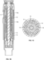
- Fig. 1B shows a cross section of one possible embodiment of the dose setting and dose delivery mechanism 2 of the present disclosure.
- Fig. 1C is a cross sectional view of the dose delivery mechanism shown in Fig. 1B , where a flexible arm 15 at the proximal end of nut 13 is shown engaged with ratchet 14.
- Piston rod 10 can also have a threaded outer surface 10a and have a non-circular cross section.
- a nut 13 having an outer surface containing longitudinal splines 13b that engage and rotationally lock the nut to a clutch such that rotation of the dose knob causes rotation of the nut 13.
- Nut 13 also has a threaded inner surface 13a that is threadedly engaged with threads 10a on the outer surface of the piston rod 10.
- Driver 12 has an outer thread 12a that cooperates with a threaded inner surface of a piston guide that is rotationally fixed relative to the housing 8.
- a brake 20 is positioned between the nut 13 and the ratchet 14 to provide a spinning through prevention feature.
- the driver 12 is rotationally fixed to the dose dial sleeve 11, which rotates during dose setting, dose cancelation and dose delivery.
- the piston rod guide can have a non-circular through hole that slidably accepts the piston rod and prevents the piston rod from rotating during dose setting and dose delivery.
- a glider 30 may be positioned between the driver and the ratchet to reduce or eliminate the friction caused by the rotating driver during dose delivery.
- Ratchet 14 is held non-rotational relative to the housing 8 by the linear guide 16, which can be configured to engage the piston rod guide.
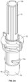
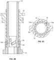
- Fig. 2C shows one example of a flexible arm 15 located on the proximal end of nut 13 engaged with an inner surface of ratchet 14.
- This design of flexible arm 15 has a nib 15a that is configured to releasably engage splines 14a inside of ratchet 14 as the nut 13 is rotated in either direction.
- the releasable configuration of the nib with the ratchet splines allows the user to conveniently correct a miss-dialed dose by rotating the dose knob in the opposite direction.
- the nut 13 and the clutch are permanently splined to each other during assembly of the dose delivery mechanism through a splined connection.
- This splined connection ensures that the clutch and nut are always rotationally fixed to each other during both dose setting and dose delivery.
- This splined connection also allows the clutch and the nut to move axially relative to each other.
- the sliding connection is necessary in order to compensate for pitch differences between the threads 10a on the piston rod 10, the outer threads on the dose sleeve and the thread 12a on the driver 12.
- the thread between driver and piston rod guide has basically the same pitch as the thread between piston rod and nut.
- a connector shown as a snap fit, that connects with a disc or foot.
- a last dose feature of the dose setting mechanism configured as an enlarged section of the piston rod designed to stop the rotation of nut 13 about threads 10a when the amount of medicament remaining in the cartridge 3 is less than the next highest predetermined dose setting.
- the enlarged section will act as a hard stop preventing the nut from further rotation along threads 10a as the user attempts to reach the desired predetermined fixed dose setting.
- a rotational biasing member for example torsion spring, could be connected to the driver 12, which is connected and rotationally fixed with the inner surface of dose sleeve through splines on the distal outer surface of the driver.
- On the proximal end of driver 12 on the outer surface is threads 12a that are engaged with matching threads on the inner distal surface of the piston rod guide.
- the thread between driver and piston guide has a significantly different pitch than the thread between dose sleeve and housing. The nut and the driver rotate together both during dose setting and dose cancellation and, as such, they perform essentially the same axial movement.
- this movement is independent from each other, i.e., the nut is turned by the clutch and performs an axial movement due to the thread to the piston rod, while the driver is rotated by the dose sleeve and performs an axial movement due to the thread to the piston guide.
- the driver is rotating during injection also, and so it actively moves in the proximal direction during injection.
- the nut does not rotate during injection and, as such, does not perform an active axial movement.
- the nut is only moving axially in the proximal direction during injection because it is being pushed axially by the driver as it rotates.
- the brake 20 is employed to provide a friction surface to ensure that the piston rod only moves in an axial direction, thus preserving dose accuracy.
- the pitch of the thread on the driver is equal to or be slightly higher than the pitch of the thread on the inside of the nut.
- the thread between the dose sleeve and the housing has a higher pitch than that of the nut and piston rod. This is desirable because it yields a mechanical advantage that makes the dose delivery process easier for the user.
- FIG. 3-8C Another embodiment of a dose delivery mechanism to prevent a spinning through failure mode is illustrated in Figs. 3-8C , where a free wheel design is employed in combination with a two position nut and ratchet assembly .
- the flexible arm 15 and nib 15a are configured such that the nut can only rotate in one direction when the nib is engaged with the splines on ratchet 14. This single direction of rotation of the nut 13 occurs during dose setting. The nut cannot be rotated during dose delivery so there is no issue regarding the failure mode of spinning through.
- this embodiment utilizes a two-position relationship between the nut and the ratchet. Figs.
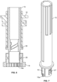
- Fig. 4 & 5 shows the nut 13 in the first position.
- Fig. 6 shows the nut in a second position where the flexible arm 15 and nib 15a are no longer engaged with the splines 14a inside ratchet 14.
- the ratchet and nut are in the relative axial position shown in Fig. 4 .
- the linear guide between ratchet and piston rod guide limits the linear movement of the ratchet.
- the distal end position of the ratchet is reached earlier than distal end position of the nut and the driver.
- the ratchet and nut are pulled apart, so that they switch from the first position ( Fig. 4 ) to the second position ( Fig. 6 ).
- the flexible arm of the nut is not in contact to the splines of the ratchet and the user can turn the dose knob back to zero if the user has inadvertently dialled a dose larger than intended or wants to merely cancel a set dose.
- the zero position the nut is pushed back into the ratchet, so that the components switch from second position back to the first position causing the flexible arm of the nut to again engage and interfer with the splines of the ratchet.
- a positioning protrusion 27 located on the nut and a radial lip 25 located on the ratchet are operatively engaged to keep the nut in either the first or the second positions. This is evident by a comparison of Figs. 4 and 6.
- Fig. 7 shows the positioning protrusion 27 on nut 13 relative to the flexible arm 15.
- Figs. 8A-8C show the radial lip 25 on the inside surface of ratchet 14 and positioned relative to splines 14a.
- a glider 30 can be positioned between the driver 12 and nut 13.
Landscapes
- Health & Medical Sciences (AREA)
- Vascular Medicine (AREA)
- Engineering & Computer Science (AREA)
- Anesthesiology (AREA)
- Biomedical Technology (AREA)
- Heart & Thoracic Surgery (AREA)
- Hematology (AREA)
- Life Sciences & Earth Sciences (AREA)
- Animal Behavior & Ethology (AREA)
- General Health & Medical Sciences (AREA)
- Public Health (AREA)
- Veterinary Medicine (AREA)
- Infusion, Injection, And Reservoir Apparatuses (AREA)
Applications Claiming Priority (3)
| Application Number | Priority Date | Filing Date | Title |
|---|---|---|---|
| US201962832636P | 2019-04-11 | 2019-04-11 | |
| PCT/EP2020/059492 WO2020207907A1 (en) | 2019-04-11 | 2020-04-03 | Dose delivery mechanism with spinning through prevention |
| EP20717609.0A EP3911384A1 (de) | 2019-04-11 | 2020-04-03 | Dosisfreisetzungsmechanismus mit durchdrückschutz |
Related Parent Applications (1)
| Application Number | Title | Priority Date | Filing Date |
|---|---|---|---|
| EP20717609.0A Division EP3911384A1 (de) | 2019-04-11 | 2020-04-03 | Dosisfreisetzungsmechanismus mit durchdrückschutz |
Publications (2)
| Publication Number | Publication Date |
|---|---|
| EP4272783A2 true EP4272783A2 (de) | 2023-11-08 |
| EP4272783A3 EP4272783A3 (de) | 2024-01-17 |
Family
ID=70224356
Family Applications (2)
| Application Number | Title | Priority Date | Filing Date |
|---|---|---|---|
| EP23199011.0A Pending EP4272783A3 (de) | 2019-04-11 | 2020-04-03 | Dosisabgabemechanismus mit durchdrehsicherung |
| EP20717609.0A Ceased EP3911384A1 (de) | 2019-04-11 | 2020-04-03 | Dosisfreisetzungsmechanismus mit durchdrückschutz |
Family Applications After (1)
| Application Number | Title | Priority Date | Filing Date |
|---|---|---|---|
| EP20717609.0A Ceased EP3911384A1 (de) | 2019-04-11 | 2020-04-03 | Dosisfreisetzungsmechanismus mit durchdrückschutz |
Country Status (5)
| Country | Link |
|---|---|
| US (1) | US20220160967A1 (de) |
| EP (2) | EP4272783A3 (de) |
| JP (1) | JP7422165B2 (de) |
| CN (2) | CN117298386A (de) |
| WO (1) | WO2020207907A1 (de) |
Families Citing this family (2)
| Publication number | Priority date | Publication date | Assignee | Title |
|---|---|---|---|---|
| USD1108627S1 (en) | 2023-10-02 | 2026-01-06 | Regeneron Pharmaceuticals, Inc. | Drug-delivery device |
| USD1109322S1 (en) | 2023-10-02 | 2026-01-13 | Regeneron Pharmaceuticals, Inc. | Drug-delivery device |
Citations (3)
| Publication number | Priority date | Publication date | Assignee | Title |
|---|---|---|---|---|
| US8747367B2 (en) | 2003-11-03 | 2014-06-10 | Haselmeier Gmbh | Injection device |
| US9694136B2 (en) | 2013-02-08 | 2017-07-04 | Haselmeier Ag | Injection device |
| WO2019011394A1 (en) | 2017-07-13 | 2019-01-17 | Haselmeier Ag | INJECTION DEVICE WITH CHOICE OF FLEXIBLE DOSE |
Family Cites Families (9)
| Publication number | Priority date | Publication date | Assignee | Title |
|---|---|---|---|---|
| WO2005018721A1 (en) * | 2003-08-12 | 2005-03-03 | Eli Lilly And Company | Medication dispensing apparatus with triple screw threads for mechanical advantage |
| RU2468829C2 (ru) * | 2007-03-23 | 2012-12-10 | Ново Нордиск А/С | Инъекционное устройство, содержащее стопорную гайку |
| DE102008011881A1 (de) * | 2008-02-29 | 2009-09-10 | Tecpharma Licensing Ag | Leerschießgeschwindigkeitsbegrenzungsbremse |
| US9757525B2 (en) * | 2009-12-01 | 2017-09-12 | Becton, Dickinson And Company | Injection pen with dial back and last dose control |
| CN103153371B (zh) * | 2010-10-13 | 2015-10-07 | 赛诺菲-安万特德国有限公司 | 用于药物递送装置的剂量设定机构 |
| EP3041542A1 (de) * | 2013-09-03 | 2016-07-13 | Sanofi | Ansteuerungsmechanismus für eine arzneimittelabgabevorrichtung |
| US10420896B2 (en) * | 2013-09-10 | 2019-09-24 | Sanofi | Drive mechanism of a drug delivery device |
| GB2530076B (en) * | 2014-09-12 | 2017-09-27 | Shaily Medical Plastics Private Ltd | Injector pens |
| TR201906808T4 (tr) * | 2015-02-27 | 2019-05-21 | Novo Nordisk As | Doz sıfırlama mekanizmasına sahip ilaç iletim cihazı. |
-
2020
- 2020-04-03 CN CN202311268784.1A patent/CN117298386A/zh active Pending
- 2020-04-03 EP EP23199011.0A patent/EP4272783A3/de active Pending
- 2020-04-03 US US17/440,970 patent/US20220160967A1/en active Pending
- 2020-04-03 JP JP2021559732A patent/JP7422165B2/ja active Active
- 2020-04-03 EP EP20717609.0A patent/EP3911384A1/de not_active Ceased
- 2020-04-03 WO PCT/EP2020/059492 patent/WO2020207907A1/en not_active Ceased
- 2020-04-03 CN CN202080027345.XA patent/CN113631208A/zh active Pending
Patent Citations (3)
| Publication number | Priority date | Publication date | Assignee | Title |
|---|---|---|---|---|
| US8747367B2 (en) | 2003-11-03 | 2014-06-10 | Haselmeier Gmbh | Injection device |
| US9694136B2 (en) | 2013-02-08 | 2017-07-04 | Haselmeier Ag | Injection device |
| WO2019011394A1 (en) | 2017-07-13 | 2019-01-17 | Haselmeier Ag | INJECTION DEVICE WITH CHOICE OF FLEXIBLE DOSE |
Also Published As
| Publication number | Publication date |
|---|---|
| WO2020207907A1 (en) | 2020-10-15 |
| CN117298386A (zh) | 2023-12-29 |
| US20220160967A1 (en) | 2022-05-26 |
| EP3911384A1 (de) | 2021-11-24 |
| CN113631208A (zh) | 2021-11-09 |
| JP2022527993A (ja) | 2022-06-07 |
| JP7422165B2 (ja) | 2024-01-25 |
| EP4272783A3 (de) | 2024-01-17 |
Similar Documents
| Publication | Publication Date | Title |
|---|---|---|
| US11642469B2 (en) | Medication delivery device | |
| EP1351732B1 (de) | Automatische einspritzeinheit mit rücksetzeigenschaft | |
| AU2009242697B2 (en) | Medication delivery device | |
| US8579867B2 (en) | Medication delivery device | |
| EP2957311B1 (de) | Medikamentenabgabevorrichtung | |
| EP3645084A1 (de) | Injektionsvorrichtung mit torsionsfederantrieb | |
| CN102083487A (zh) | 药物输送设备 | |
| EP2999501A1 (de) | Arzneimittelabgabevorrichtung mit einem mittel zur sperrung der aktivierung eines ausstossmechanismus | |
| CN109641111B (zh) | 具有过扭矩保护机构的药物输送装置 | |
| EP3316942B1 (de) | Wirkstofffreisetzungsvorrichtung mit spülmechanismus | |
| GB2530076A (en) | Injector pens | |
| EP3302629A1 (de) | Arzneimittelabgabevorrichtung mit multifunktioneller vorspannungsstruktur | |
| EP4272783A2 (de) | Dosisabgabemechanismus mit durchdrehsicherung | |
| EP3463519B1 (de) | Betätigungsmechanismus | |
| JP2023164973A (ja) | 注射デバイスのための駆動機構 | |
| WO2018078187A1 (en) | Drug delivery device |
Legal Events
| Date | Code | Title | Description |
|---|---|---|---|
| PUAI | Public reference made under article 153(3) epc to a published international application that has entered the european phase |
Free format text: ORIGINAL CODE: 0009012 |
|
| STAA | Information on the status of an ep patent application or granted ep patent |
Free format text: STATUS: THE APPLICATION HAS BEEN PUBLISHED |
|
| AC | Divisional application: reference to earlier application |
Ref document number: 3911384 Country of ref document: EP Kind code of ref document: P |
|
| AK | Designated contracting states |
Kind code of ref document: A2 Designated state(s): AL AT BE BG CH CY CZ DE DK EE ES FI FR GB GR HR HU IE IS IT LI LT LU LV MC MK MT NL NO PL PT RO RS SE SI SK SM TR |
|
| PUAL | Search report despatched |
Free format text: ORIGINAL CODE: 0009013 |
|
| P01 | Opt-out of the competence of the unified patent court (upc) registered |
Effective date: 20231113 |
|
| AK | Designated contracting states |
Kind code of ref document: A3 Designated state(s): AL AT BE BG CH CY CZ DE DK EE ES FI FR GB GR HR HU IE IS IT LI LT LU LV MC MK MT NL NO PL PT RO RS SE SI SK SM TR |
|
| RIC1 | Information provided on ipc code assigned before grant |
Ipc: A61M 5/315 20060101AFI20231214BHEP |
|
| STAA | Information on the status of an ep patent application or granted ep patent |
Free format text: STATUS: REQUEST FOR EXAMINATION WAS MADE |
|
| 17P | Request for examination filed |
Effective date: 20240717 |
|
| RBV | Designated contracting states (corrected) |
Designated state(s): AL AT BE BG CH CY CZ DE DK EE ES FI FR GB GR HR HU IE IS IT LI LT LU LV MC MK MT NL NO PL PT RO RS SE SI SK SM TR |
|
| STAA | Information on the status of an ep patent application or granted ep patent |
Free format text: STATUS: EXAMINATION IS IN PROGRESS |
|
| 17Q | First examination report despatched |
Effective date: 20250729 |