EP4271937B1 - Verfahren zur erzeugung von wasserdampf mit definierten dampfparametern - Google Patents
Verfahren zur erzeugung von wasserdampf mit definierten dampfparametern Download PDFInfo
- Publication number
- EP4271937B1 EP4271937B1 EP22710557.4A EP22710557A EP4271937B1 EP 4271937 B1 EP4271937 B1 EP 4271937B1 EP 22710557 A EP22710557 A EP 22710557A EP 4271937 B1 EP4271937 B1 EP 4271937B1
- Authority
- EP
- European Patent Office
- Prior art keywords
- steam
- parameters
- turbine
- generating
- generator
- Prior art date
- Legal status (The legal status is an assumption and is not a legal conclusion. Google has not performed a legal analysis and makes no representation as to the accuracy of the status listed.)
- Active
Links
Images
Classifications
-
- F—MECHANICAL ENGINEERING; LIGHTING; HEATING; WEAPONS; BLASTING
- F22—STEAM GENERATION
- F22B—METHODS OF STEAM GENERATION; STEAM BOILERS
- F22B1/00—Methods of steam generation characterised by form of heating method
- F22B1/003—Methods of steam generation characterised by form of heating method using combustion of hydrogen with oxygen
-
- F—MECHANICAL ENGINEERING; LIGHTING; HEATING; WEAPONS; BLASTING
- F01—MACHINES OR ENGINES IN GENERAL; ENGINE PLANTS IN GENERAL; STEAM ENGINES
- F01K—STEAM ENGINE PLANTS; STEAM ACCUMULATORS; ENGINE PLANTS NOT OTHERWISE PROVIDED FOR; ENGINES USING SPECIAL WORKING FLUIDS OR CYCLES
- F01K25/00—Plants or engines characterised by use of special working fluids, not otherwise provided for; Plants operating in closed cycles and not otherwise provided for
- F01K25/005—Plants or engines characterised by use of special working fluids, not otherwise provided for; Plants operating in closed cycles and not otherwise provided for the working fluid being steam, created by combustion of hydrogen with oxygen
Definitions
- the invention relates to a method for generating steam with defined steam parameters according to independent patent claim 1.
- Steam is often used in processes and in heat supply; the term industrial processes is generally used below.
- a typical application is the provision of heat, for example for cooking, evaporation or distillation processes; drying processes or the provision of heat for endothermic reactions in the chemical industry can also be carried out with steam.
- Steam used in industrial processes is often also referred to as process steam.
- a further embodiment of the invention provides that at least part of the fresh steam is removed before entering the steam turbine and fed directly to an industrial process.
- the steam parameters of the fresh steam which is produced during the internal combustion of hydrogen with oxygen, can be influenced so that at least part of the fresh steam can be fed directly to the industrial process. If further steam with lower steam parameters is required, this can be provided by expanding another part of the fresh steam in a steam turbine.
- a further embodiment of the invention provides that the mechanical energy generated by the steam turbine is used to drive machines and/or to generate electrical energy with the help of a generator.
- the dual use of steam which is also referred to as combined heat and power, enables particularly high overall efficiencies to be achieved, which increase the economic efficiency of the process according to the invention.
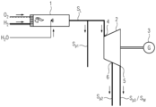
- the figure shows a system that is suitable for carrying out the method according to the invention.
- the figure shows only the essential elements that are necessary for explaining the components necessary for the process and is not a scaled representation.
- the plant for carrying out the method according to the invention essentially comprises a steam generator 1 and a steam turbine 2 connected downstream of the steam generator.
- steam is generated by internal combustion and not, as is usual, by pure heat supply (partly from external combustion), as is the case, for example, when using a conventional boiler.
- the internal combustion takes place in a steam generator 1 called a Clean Steam Generator (CSG).
- CSG 1 is characterized by a pressurized, internal combustion of hydrogen H 2 with oxygen O 2 and the addition of water H 2 O 2 (regardless of the state of aggregation), whereby fresh steam S L is produced with defined steam parameters (pressure, temperature%) and in a defined quantity and purity.
- the fresh steam S L is then fed to the steam turbine 2 downstream of the CSG.
- the fresh steam is expanded to lower steam parameters along an expansion section, which extends from a steam turbine inlet 4 to a steam turbine outlet 5.
- the steam can be extracted along the expansion section through one or more intermediate steam extractions and fed to the respective industrial process as process steam S P2 .
- the remaining part of the steam is completely expanded along the expansion section and leaves the steam turbine at the steam turbine outlet 5 as exhaust steam S W .
- the exhaust steam can then be fed to a condenser or fed to another industrial process as process steam S P3 .
- the steam can be expanded to lower steam parameters. If exhaust steam is fed to the condenser or as process steam to an industrial process, the steam turbine 1 is designed as a (extraction) condensation turbine or as a (extraction) back-pressure turbine.
- part or all of the fresh steam can be diverted before the steam turbine and fed directly to an industrial process as process steam S P1 .
- the distribution of the steam S P1 - S P3 to the different industrial processes can vary both in terms of time and the respective amount of steam.
- the steam turbine drives a generator 3 to generate electrical energy; alternatively, the steam turbine can also drive a working machine (compressor, pump, etc.).
- the steam turbine can be designed in one or more stages and also consist of one or more housings. It is also possible for the fresh steam to be divided into several steam turbines, expanded and fed to the different industrial processes.
- the various steam turbines and housings can be operated at the same or different speeds and do not necessarily have to be mechanically coupled to one another via a shaft (several generators) and do not necessarily have to serve the same purpose (e.g. high-pressure turbine as a mechanical drive for a drive machine, low-pressure turbine as a drive for a generator).
- the process according to the invention for generating steam offers clear advantages over the conventional process both in terms of fuel utilization and operational flexibility (the CSG can operate at higher load gradients than a conventional boiler).
Landscapes
- Engineering & Computer Science (AREA)
- Combustion & Propulsion (AREA)
- Chemical & Material Sciences (AREA)
- Mechanical Engineering (AREA)
- General Engineering & Computer Science (AREA)
- Life Sciences & Earth Sciences (AREA)
- Physics & Mathematics (AREA)
- Thermal Sciences (AREA)
- Sustainable Energy (AREA)
- Sustainable Development (AREA)
- Engine Equipment That Uses Special Cycles (AREA)
- Air Supply (AREA)
- Feeding And Controlling Fuel (AREA)
Description
- Die Erfindung betrifft ein Verfahren zur Erzeugung von Wasserdampf mit definierten Dampfparametern gemäß dem unabhängigen Patentanspruch 1.
- Wasserdampf wir häufig in Prozessen sowie in der Wärmeversorgung verwendet, nachfolgend wird allgemein der Begriff Industrieprozesse verwendet. Ein typisches Anwendungsgebiet ist die Bereitstellung von Wärme, beispielsweise für Koch-, Eindampf- oder Destillationsprozesse, darüber hinaus können auch Trocknungsprozesse oder die Wärmebereitstellung bei endothermen Reaktionen in der Chemieindustrie mit Wasserdampf realisiert werden. Wasserdampf welcher in industriellen Prozessen verwendet wird, wird dabei häufig auch als Prozessdampf bezeichnet.
- Die Erzeugung von Wasserdampf für Industrieprozesse stellt einerseits hohe Anforderungen an das zur Erzeugung benötigte Equipment, andererseits beeinflusst die Erzeugung auch wesentlich den Energieverbrauch. Die klassische Wasserdampferzeugung mit Hilfe eines konventionellen Kessels (und ggf. einer Dampfturbine) ist in der Betriebsflexibilität (Lastgradienten, Anfahrzeit, ...) limitiert. Zudem bedingt der Einsatz eines Kessels hohe Investitionskosten. Der Kessel wird in der Regel mit fossilen Energieträgern befeuert, was sich negativ auf die Emissionen der Anlage und somit auch auf ökologische und betriebswirtschaftliche Aspekte auswirkt.
- Das Dokument
DE102015218502 A1 offenbart ein Dampfturbinenkraftwerk, welches eine Brennkammer 11 umfasst, in der Sauerstoff mit Wasserstoff verbrannt wird und wobei dem Sauerstoff kurz vor Zuleiten in die Brennkammer 11 Wasserdampf zugeführt wird. Aufgabe der vorliegenden Erfindung ist es, die Nachteile aus dem Stand der Technik bei der Bereitstellung von Wasserdampf mit definierten Dampfparametern zu vermeiden und einen effektiveren Prozess zur Bereitstellung des Wasserdampfs aufzuzeigen. - Die Aufgabe wird gelöst durch die Merkmale des unabhängigen Patentanspruchs 1.
- Weitere Ausgestaltungen der Erfindung, die einzeln oder in Kombination miteinander einsetzbar sind, sind Gegenstand der Unteransprüche.
- Das erfindungsgemäße Verfahren zur Erzeugung von Wasserdampf mit definierten Dampfparametern zeichnet sich durch die folgenden Verfahrensschritte aus:
- Druck beaufschlagte, interne Verbrennung von Wasserstoff mit Sauerstoffund unter Zugabe von Wasser (unabhängig vom Aggregatzustand), in einem Dampferzeuger und Erzeugung von Frischdampf;
- Zuführen des im Dampferzeuger erzeugten Frischdampfs zu einer Dampfturbine;
- Expandieren des Frischdampfs entlang einer Expansionsstrecke in der Dampfturbine;
- Entnehmen von Zwischendampf entlang der Expansionsstrecke und/oder Entnehmen von Abdampf am Ende der Expansionsstrecke mit definierten Dampfparametern und
- Zuführen des entnommenen Zwischendampfs und/oder Abdampfs zu einem nachfolgenden Industrieprozess.
- Im Gegensatz zur klassischen Dampferzeugung mit Hilfe eines konventionellen Kessels ergibt sich eine deutlich erhöhte Betriebsflexibilität (Lastgradienten, Anfahrzeit, ...). Insbesondere ergeben sich durch die interne Verbrennung von Wasserstoff mit Sauerstoff sehr kurze Anfahrzeiten. Durch die Zugabe von Wasser (unabhängig vom Aggregatzustand) kann bereits eine (Vor-)Konditionierung des Frischdampfes erfolgen. Das Zuführen und Entspannen des Frischdampfes in der Dampfturbine ermöglicht die Bereitstellung von Wasserdampf mit definierten und ggf. unterschiedlichen Dampfparametern. Hierzu kann Wasserdampf mit den entsprechenden Dampfparametern durch eine oder mehrere Zwischendampfentnahmen entlang der Expansionsstecke innerhalb der Dampfturbine entnommen und dem jeweiligen Industrieprozess zugeführt werden. Alternativ oder zusätzlich zur Dampfturbinen als Regelorgan der Prozessdampfparameter können auch andere technische Vorrichtungen wie z.B. Drosseln (z.B. in Kombination mit Wassereinspitzung oder sonstiger Kühlung) eingesetzt werden.
- Eine Ausgestaltung der Erfindung sieht vor, dass der zur Verbrennung genutzte Wasserstoff und Sauerstoff mittels regenerativer Energie erzeugt wird. Hierdurch kann die Erzeugung des Prozessdampfs völlig emissionsfrei erfolgen.
- Eine weitere Ausgestaltung der Erfindung sieht vor, dass wenigstens ein Teil des Frischdampfes vor dem Eintritt in die Dampfturbine entnommen und direkt einem Industrieprozess zugeführt wird. Durch die Zugabe von Wasser können die Dampfparameter des Frischdampfs, der bei der internen Verbrennung von Wasserstoff mit Sauerstoff entsteht, so beeinflusst werden, dass zumindest ein Teil des Frischdampfs direkt dem Industrieprozess zugeführt werden kann. Wird weiterer Wasserdampf mit niedrigeren Dampfparametern benötigt, kann dieser durch Expansion eines weiteren Teils des Frischdampf in einer Dampfturbine bereitgestellt werden.
- Eine weitere Ausgestaltung der Erfindung sieht vor, dass die von der Dampfturbine erzeugte mechanische Energie zum Antreiben von Maschinen und/oder zum Erzeugen elektrischer Energie mit Hilfe eines Generators genutzt wird. Durch die doppelte Nutzung des Dampfes, welche auch als Kraft-Wärme-Kopplung bezeichnet wird, können besonders hohe Gesamtwirkungsgrade erreicht werden, die die Wirtschaftlichkeit des erfindungsgemäßen Verfahrens erhöhen.
- Weitere Vorteile der Erfindung werden nachfolgend Anhand einer Figur erläutert. Die Figur zeigt eine Anlage, die zur Durchführung des erfindungsgemäßen Verfahrens geeignet ist. Die Figur zeigt nur die wesentlichen, zur Erläuterung des Verfahrens notwendigen Bauteile und stellt keine maßstabsgerechte Darstellung dar.
- Die Anlage zur Durchführung des erfindungsgemäßen Verfahrens umfasst im Wesentlichen einen Dampferzeuger 1 und eine dem Dampferzeuger nachgeschaltete Dampfturbine 2.
- Bei dem erfindungsgemäßen Verfahren erfolgt die Dampferzeugung durch innere Verbrennung und nicht wie sonst üblich, durch reine Wärmezufuhr (teils aus externer Verbrennung), wie beispielsweise bei der Verwendung eines konventionellen Kessels.
- Die interne Verbrennung erfolgt dabei in einem als Clean Steam Generator, CSG, bezeichneten Dampferzeuger 1. Der CSG 1 wird durch eine Druck beaufschlagte, interne Verbrennung von Wasserstoff H2 mit Sauerstoff O2 und der Zugabe von Wasser H2O2 (unabhängig vom Aggregatzustand) charakterisiert, wobei Frischdampf SL mit definierten Dampfparametern (Druck, Temperatur...) sowie in einer definierten Menge und Reinheit entsteht.
- Der Frischdampf SL wird anschließend, der dem CSG nachgeschalteten Dampfturbine 2, zugeführt. Entlang einer Expansionsstrecke, welche sich von einem Dampfturbineneintritt 4 bis zu einem Dampfturbinenaustritt 5 erstreckt, wird der Frischdampf auf niedrigere Dampfparameter entspannt. Je nachdem welche Dampfparameter für den jeweiligen Industrieprozess gefordert sind, kann der Dampf entlang der Expansionsstrecke durch eine oder mehrere Zwischendampfentnahmen entnommen werden und als Prozessdampf SP2, dem jeweiligen Industrieprozess zugeführt werden. Der restliche Teil des Dampfes wird vollständig entlang der Expansionsstrecke entspannt und verlässt die Dampfturbine am Dampfturbinenaustritt 5 als Abdampf SW. Der Abdampf kann dann einem Kondensator zugeführt oder einem weiteren Industrieprozess als Prozessdampf SP3 zugeführt werden. Je nachdem, ob der Dampf am Ende der Expansionsstrecke als Abdampf dem Kondensator oder als Prozessdampf einem Industrieprozess zugeführt wird, ist die Dampfturbine 1 als (Entnahme-) Kondensationsturbine oder als (Entnahme-) Gegendruckturbine ausgebildet.
- Erfordert ein Industrieprozess sehr hohe Dampfparameter, so kann ein Teil, oder der komplette Frischdampf, bereits vor der Dampfturbine abgeleitet und als Prozessdampf SP1 unmittelbar einem Industrieprozess zugeführt werden. Die Aufteilung des Wasserdampfs SP1 - SP3 auf die unterschiedlichen Industrieprozesse kann sowohl zeitlich, als auch von der jeweiligen Dampfmenge variieren.
- Die Dampfturbine treibt im Ausführungsbeispiel einen Generator 3 zur Erzeugung elektrischer Energie an, alternativ kann die Dampfturbine auch eine Arbeitsmaschine (Kompressor, Pumpe,....) antreiben.
- Die Dampfturbine kann ein- oder mehrstufig ausgebildet sein und zudem aus einem oder mehreren Gehäusen bestehen. Weiterhin ist es möglich, dass der Frischdampf auf mehrere Dampfturbinen aufgeteilt, entspannt und den unterschiedlichen Industrieprozessen zugeführt wird. Die verschiedenen Dampfturbinen und Gehäuse können mit gleicher oder unterschiedlicher Drehzahl betrieben werden und müssen nicht zwangsläufig mechanisch über eine Welle miteinander gekoppelt sein (mehrere Generatoren)und auch nicht zwangsläufig dem gleichen Zweck dienen (z.B. Hochdruckturbine als mechanischer Antrieb einer Antriebsmaschine, Niederdruckturbine als Antrieb eines Generators.)
- Der zur Verbrennung genutzte Wasserstoff und Sauerstoff kann vorzugsweise mittels regenerativer Energie erzeugt und anschließend für die weitere Verwendung im CSG gespeichert werden. Durch die regenerative Erzeugung des Wasserstoffs und des Sauerstoffs kann das erfindungsgemäße Verfahren zur Erzeugung von Prozessdampf CO2-frei erfolgen.
- Das erfindungsgemäße Verfahren zur Erzeugung von Wasserdampf bietet sowohl hinsichtlich der Brennstoffausnutzung als auch der Betriebsflexibilität (Der CSG kann höhere Lastgradienten fahren als ein konventioneller Kessel) deutliche Vorteile gegenüber dem herkömmlichen Verfahren.
Claims (4)
- Verfahren zur Erzeugung von Wasserdampf mit definierten Dampfparametern umfassend die folgenden Verfahrensschritte:- Druck beaufschlagte, interne Verbrennung von Wasserstoff mit Sauerstoff unter Zugabe von Wasser, in einem Dampferzeuger (1) und Erzeugung von Frischdampf;- Zuführen des im Dampferzeuger (1) erzeugten Frischdampfs zu einer Dampfturbine (2);- Expandieren des Frischdampfs entlang einer Expansionsstrecke in der Dampfturbine (2);- Entnehmen von Zwischendampf entlang der Expansionsstrecke und/oder Entnehmen von Abdampf am Ende der Expansionsstrecke mit definierten Dampfparametern und- Zuführen des entnommenen Zwischendampfs und/oder Abdampfs zu einem nachfolgenden Industrieprozess.
- Verfahren zur Erzeugung von Wasserdampf mit definierten Dampfparametern nach Anspruch 1,
wobei
der zur Verbrennung genutzte Wasserstoff und Sauerstoff mittels regenerativer Energie erzeugt wird. - Verfahren zur Erzeugung von Wasserdampf mit definierten Dampfparametern nach Anspruch 1 oder 2,
wobei
wenigstens ein Teil des Frischdampfes vor dem Eintritt in die Dampfturbine (2) entnommen und einem Industrieprozess zugeführt wird. - Verfahren zur Erzeugung von Wasserdampf mit definierten Dampfparametern nach einem der vorherigen Ansprüche,
wobei
die von der Dampfturbine (1) erzeugte mechanische Energie zum Antreiben von Maschinen oder zum Erzeugen elektrischen Stroms mit Hilfe eines Generators (3) genutzt wird.
Applications Claiming Priority (2)
| Application Number | Priority Date | Filing Date | Title |
|---|---|---|---|
| DE102021202617.6A DE102021202617A1 (de) | 2021-03-18 | 2021-03-18 | Verfahren zur Erzeugung von Wasserdampf mit definierten Dampfparametern |
| PCT/EP2022/055451 WO2022194564A1 (de) | 2021-03-18 | 2022-03-03 | Verfahren zur erzeugung von wasserdampf mit definierten dampfparametern |
Publications (3)
| Publication Number | Publication Date |
|---|---|
| EP4271937A1 EP4271937A1 (de) | 2023-11-08 |
| EP4271937C0 EP4271937C0 (de) | 2024-12-18 |
| EP4271937B1 true EP4271937B1 (de) | 2024-12-18 |
Family
ID=80780782
Family Applications (1)
| Application Number | Title | Priority Date | Filing Date |
|---|---|---|---|
| EP22710557.4A Active EP4271937B1 (de) | 2021-03-18 | 2022-03-03 | Verfahren zur erzeugung von wasserdampf mit definierten dampfparametern |
Country Status (6)
| Country | Link |
|---|---|
| EP (1) | EP4271937B1 (de) |
| JP (1) | JP2024511757A (de) |
| CN (1) | CN116997749A (de) |
| BR (1) | BR112023017286A2 (de) |
| DE (1) | DE102021202617A1 (de) |
| WO (1) | WO2022194564A1 (de) |
Citations (2)
| Publication number | Priority date | Publication date | Assignee | Title |
|---|---|---|---|---|
| DE202017003690U1 (de) * | 2017-07-13 | 2018-10-16 | Thomas Lamla | Wasserstoff-Dampf-Kraft-Werk |
| DE102018126496A1 (de) * | 2018-10-24 | 2020-04-30 | HK Innovation UG (haftungsbeschränkt) | Vorrichtung und Verfahren zum Antreiben eines Fahrzeugs, Flugzeugs, Schiffs oder dergleichen sowie Fahrzeug, Flugzeug, Schiff oder dergleichen, welches eine derartige Vorrichtung aufweist und/oder mit einem solchen Verfahren betreibbar ist |
Family Cites Families (21)
| Publication number | Priority date | Publication date | Assignee | Title |
|---|---|---|---|---|
| FR605154A (fr) * | 1925-01-19 | 1926-05-20 | Alsacienne Constr Meca | Turbine à vapeur à plusieurs soutirages de vapeur |
| CH293528A (de) * | 1951-09-19 | 1953-09-30 | Oerlikon Maschf | Dampfturbine mit mehrfacher Dampfentnahme. |
| CH424811A (de) * | 1962-04-13 | 1966-11-30 | Siemens Ag | Dampfkraftanlage |
| US3427803A (en) * | 1967-09-01 | 1969-02-18 | United Aircraft Corp | Oxidizer to fuel ratio control responsive to condensuctor pressure |
| US4148185A (en) * | 1977-08-15 | 1979-04-10 | Westinghouse Electric Corp. | Double reheat hydrogen/oxygen combustion turbine system |
| US4377067A (en) * | 1980-11-24 | 1983-03-22 | Deutsche Forschungs- Und Versuchsanstalt Fur Luft- Und Raumfahrt | Steam generator |
| CA2088947C (en) | 1993-02-05 | 1996-07-16 | Daniel A. Warkentin | Hydrogen fuelled gas turbine |
| JPH06307207A (ja) * | 1993-04-23 | 1994-11-01 | Mitsubishi Heavy Ind Ltd | 水素酸素燃焼タービン発電プラント |
| US5782081A (en) * | 1994-05-31 | 1998-07-21 | Pyong Sik Pak | Hydrogen-oxygen burning turbine plant |
| US5775091A (en) * | 1996-10-21 | 1998-07-07 | Westinghouse Electric Corporation | Hydrogen fueled power plant |
| EP0900921A3 (de) | 1997-09-05 | 2000-01-26 | Mitsubishi Heavy Industries, Ltd. | Turbinenanlage mit Verbrennung von Wasserstoff |
| JPH11173108A (ja) * | 1997-12-05 | 1999-06-29 | Jgc Corp | 熱電併給プラント |
| JPH11343814A (ja) * | 1998-05-28 | 1999-12-14 | Mitsubishi Heavy Ind Ltd | ボイラタービン発電装置における蒸気制御方法 |
| JP2000161015A (ja) * | 1998-11-19 | 2000-06-13 | Takeshi Hatanaka | 密閉サイクル動力システム |
| JP4718910B2 (ja) * | 2005-06-16 | 2011-07-06 | 株式会社東芝 | 水素製造装置および水素製造方法 |
| JP4578354B2 (ja) * | 2005-08-30 | 2010-11-10 | 株式会社日立エンジニアリング・アンド・サービス | 蒸気タービンプラントの廃熱利用設備 |
| JP4794254B2 (ja) * | 2005-09-26 | 2011-10-19 | 中国電力株式会社 | 蒸気タービンプラントおよびその運転方法 |
| US20100314878A1 (en) * | 2009-06-16 | 2010-12-16 | Dewitt Monte Douglas | Direct Generation of Steam Motive Flow by Water-Cooled Hydrogen/Oxygen Combustion |
| US20150082799A1 (en) * | 2013-09-24 | 2015-03-26 | Billings Energy Corporation | High Efficiency Hydrogen Turbine |
| DE102015218502A1 (de) * | 2015-09-25 | 2017-03-30 | Siemens Aktiengesellschaft | Dampfturbinenkraftwerk mit Wasserstoffverbrennung unter Einbindung einer Vergasungseinrichtung |
| JP6684453B2 (ja) * | 2017-09-11 | 2020-04-22 | 住友金属鉱山株式会社 | 蒸気タービン発電機の抽気制御方法及びその制御装置 |
-
2021
- 2021-03-18 DE DE102021202617.6A patent/DE102021202617A1/de not_active Ceased
-
2022
- 2022-03-03 EP EP22710557.4A patent/EP4271937B1/de active Active
- 2022-03-03 JP JP2023557123A patent/JP2024511757A/ja active Pending
- 2022-03-03 WO PCT/EP2022/055451 patent/WO2022194564A1/de not_active Ceased
- 2022-03-03 CN CN202280021865.9A patent/CN116997749A/zh active Pending
- 2022-03-03 BR BR112023017286A patent/BR112023017286A2/pt unknown
Patent Citations (2)
| Publication number | Priority date | Publication date | Assignee | Title |
|---|---|---|---|---|
| DE202017003690U1 (de) * | 2017-07-13 | 2018-10-16 | Thomas Lamla | Wasserstoff-Dampf-Kraft-Werk |
| DE102018126496A1 (de) * | 2018-10-24 | 2020-04-30 | HK Innovation UG (haftungsbeschränkt) | Vorrichtung und Verfahren zum Antreiben eines Fahrzeugs, Flugzeugs, Schiffs oder dergleichen sowie Fahrzeug, Flugzeug, Schiff oder dergleichen, welches eine derartige Vorrichtung aufweist und/oder mit einem solchen Verfahren betreibbar ist |
Also Published As
| Publication number | Publication date |
|---|---|
| EP4271937C0 (de) | 2024-12-18 |
| EP4271937A1 (de) | 2023-11-08 |
| WO2022194564A1 (de) | 2022-09-22 |
| BR112023017286A2 (pt) | 2023-09-26 |
| JP2024511757A (ja) | 2024-03-15 |
| CN116997749A (zh) | 2023-11-03 |
| DE102021202617A1 (de) | 2022-09-22 |
Similar Documents
| Publication | Publication Date | Title |
|---|---|---|
| DE69429769T2 (de) | Mehrwellen, zwischenheizungsgasturbine mit zwischenkühlung und wärmerückgewinnung | |
| DE69533558T2 (de) | Gaserzeuger für ein energie-erzeugungssystem mit geringer umweltbelastung | |
| EP0439754B1 (de) | Verfahren zum Anfahren einer Kombianlage | |
| DE102009026211B4 (de) | Verfahren und Systeme zum Betreiben eines Kombikraftwerks | |
| EP3469190B1 (de) | Kraftwerk mit wärmespeicher | |
| EP0674099A1 (de) | Verfahren zur Kühlung von thermische belasteten Komponenten einer Gasturbogruppe | |
| WO1992007392A1 (de) | Verfahren und anlage zur kombinierten erzeugung elektrischer und mechanischer energie | |
| EP2898201B1 (de) | Verfahren und anlage zur energiegewinnung bei der entspannung von prozesserdgas | |
| DE2437782C3 (de) | Verfahren zum Anfahren einer Gasturbinen-Anlage zur Stromerzeugung aus Brenngas von einem Kohle-Druckvergaser | |
| EP1377730B1 (de) | Dampfkraftwerk mit nachrüstsatz und verfahren zum nachrüsten eines dampfkraftwerks | |
| DE69812811T2 (de) | Verfahren und Anordnung für Kombikraftwerk | |
| EP1286030B1 (de) | Gas- und Luftturbinenanlage | |
| EP2136035A1 (de) | Betrieb einer Gas- und Dampfturbinenanlage mittels Frequenzumrichter | |
| EP1038094B1 (de) | Mehrstufiger dampfkraft-/arbeitsprozess für die elektroenergiegewinnung im kreisprozess sowie anordnung zu seiner durchführung | |
| DE102009038323A1 (de) | Verfahren und Vorrichtung zur Verwertung von Biomasse | |
| WO2021185498A1 (de) | Anlage zur nutzung von in einem abgas- oder abluftstrom einer industriellen produktionsanlage enthaltener wärmeenergie | |
| EP2393708B1 (de) | Verbrennungskraftmaschinenanlage mit abgasenergierückgewinnung für schwimmende einrichtungen | |
| EP4271937A1 (de) | Verfahren zur erzeugung von wasserdampf mit definierten dampfparametern | |
| EP3643888B1 (de) | Verfahren zum betreiben einer chemischen anlage | |
| EP2305964A1 (de) | Dampfkraftwerk | |
| EP2084373A2 (de) | Verfahren zum erzeugen von mischdampf | |
| EP4288643B1 (de) | Erzeugung von elektrischer energie aus wasserstoff und sauerstoff | |
| EP4105551B1 (de) | Verfahren zum erzeugen von elektrischer energie | |
| EP2006510A2 (de) | Gasturbinenanlage und Verfahren zum Betrieb | |
| DE953929C (de) | Gasturbinenanlage mit einer Hilfs- oder Nachbrennkammer |
Legal Events
| Date | Code | Title | Description |
|---|---|---|---|
| STAA | Information on the status of an ep patent application or granted ep patent |
Free format text: STATUS: UNKNOWN |
|
| STAA | Information on the status of an ep patent application or granted ep patent |
Free format text: STATUS: THE INTERNATIONAL PUBLICATION HAS BEEN MADE |
|
| PUAI | Public reference made under article 153(3) epc to a published international application that has entered the european phase |
Free format text: ORIGINAL CODE: 0009012 |
|
| STAA | Information on the status of an ep patent application or granted ep patent |
Free format text: STATUS: REQUEST FOR EXAMINATION WAS MADE |
|
| 17P | Request for examination filed |
Effective date: 20230731 |
|
| AK | Designated contracting states |
Kind code of ref document: A1 Designated state(s): AL AT BE BG CH CY CZ DE DK EE ES FI FR GB GR HR HU IE IS IT LI LT LU LV MC MK MT NL NO PL PT RO RS SE SI SK SM TR |
|
| STAA | Information on the status of an ep patent application or granted ep patent |
Free format text: STATUS: EXAMINATION IS IN PROGRESS |
|
| 17Q | First examination report despatched |
Effective date: 20240503 |
|
| DAV | Request for validation of the european patent (deleted) | ||
| DAX | Request for extension of the european patent (deleted) | ||
| GRAP | Despatch of communication of intention to grant a patent |
Free format text: ORIGINAL CODE: EPIDOSNIGR1 |
|
| STAA | Information on the status of an ep patent application or granted ep patent |
Free format text: STATUS: GRANT OF PATENT IS INTENDED |
|
| INTG | Intention to grant announced |
Effective date: 20240802 |
|
| GRAS | Grant fee paid |
Free format text: ORIGINAL CODE: EPIDOSNIGR3 |
|
| GRAA | (expected) grant |
Free format text: ORIGINAL CODE: 0009210 |
|
| STAA | Information on the status of an ep patent application or granted ep patent |
Free format text: STATUS: THE PATENT HAS BEEN GRANTED |
|
| AK | Designated contracting states |
Kind code of ref document: B1 Designated state(s): AL AT BE BG CH CY CZ DE DK EE ES FI FR GB GR HR HU IE IS IT LI LT LU LV MC MK MT NL NO PL PT RO RS SE SI SK SM TR |
|
| REG | Reference to a national code |
Ref country code: CH Ref legal event code: EP |
|
| REG | Reference to a national code |
Ref country code: DE Ref legal event code: R096 Ref document number: 502022002439 Country of ref document: DE |
|
| REG | Reference to a national code |
Ref country code: IE Ref legal event code: FG4D Free format text: LANGUAGE OF EP DOCUMENT: GERMAN |
|
| U01 | Request for unitary effect filed |
Effective date: 20241218 |
|
| U07 | Unitary effect registered |
Designated state(s): AT BE BG DE DK EE FI FR IT LT LU LV MT NL PT RO SE SI Effective date: 20250113 |
|
| PG25 | Lapsed in a contracting state [announced via postgrant information from national office to epo] |
Ref country code: HR Free format text: LAPSE BECAUSE OF FAILURE TO SUBMIT A TRANSLATION OF THE DESCRIPTION OR TO PAY THE FEE WITHIN THE PRESCRIBED TIME-LIMIT Effective date: 20241218 |
|
| PG25 | Lapsed in a contracting state [announced via postgrant information from national office to epo] |
Ref country code: NO Free format text: LAPSE BECAUSE OF FAILURE TO SUBMIT A TRANSLATION OF THE DESCRIPTION OR TO PAY THE FEE WITHIN THE PRESCRIBED TIME-LIMIT Effective date: 20250318 |
|
| PG25 | Lapsed in a contracting state [announced via postgrant information from national office to epo] |
Ref country code: GR Free format text: LAPSE BECAUSE OF FAILURE TO SUBMIT A TRANSLATION OF THE DESCRIPTION OR TO PAY THE FEE WITHIN THE PRESCRIBED TIME-LIMIT Effective date: 20250319 |
|
| PG25 | Lapsed in a contracting state [announced via postgrant information from national office to epo] |
Ref country code: RS Free format text: LAPSE BECAUSE OF FAILURE TO SUBMIT A TRANSLATION OF THE DESCRIPTION OR TO PAY THE FEE WITHIN THE PRESCRIBED TIME-LIMIT Effective date: 20250318 |
|
| U20 | Renewal fee for the european patent with unitary effect paid |
Year of fee payment: 4 Effective date: 20250325 |
|
| PG25 | Lapsed in a contracting state [announced via postgrant information from national office to epo] |
Ref country code: SM Free format text: LAPSE BECAUSE OF FAILURE TO SUBMIT A TRANSLATION OF THE DESCRIPTION OR TO PAY THE FEE WITHIN THE PRESCRIBED TIME-LIMIT Effective date: 20241218 |
|
| PG25 | Lapsed in a contracting state [announced via postgrant information from national office to epo] |
Ref country code: PL Free format text: LAPSE BECAUSE OF FAILURE TO SUBMIT A TRANSLATION OF THE DESCRIPTION OR TO PAY THE FEE WITHIN THE PRESCRIBED TIME-LIMIT Effective date: 20241218 |
|
| PG25 | Lapsed in a contracting state [announced via postgrant information from national office to epo] |
Ref country code: ES Free format text: LAPSE BECAUSE OF FAILURE TO SUBMIT A TRANSLATION OF THE DESCRIPTION OR TO PAY THE FEE WITHIN THE PRESCRIBED TIME-LIMIT Effective date: 20241218 |
|
| PG25 | Lapsed in a contracting state [announced via postgrant information from national office to epo] |
Ref country code: IS Free format text: LAPSE BECAUSE OF FAILURE TO SUBMIT A TRANSLATION OF THE DESCRIPTION OR TO PAY THE FEE WITHIN THE PRESCRIBED TIME-LIMIT Effective date: 20250418 |
|
| PGFP | Annual fee paid to national office [announced via postgrant information from national office to epo] |
Ref country code: CH Payment date: 20250401 Year of fee payment: 4 |
|
| PG25 | Lapsed in a contracting state [announced via postgrant information from national office to epo] |
Ref country code: SK Free format text: LAPSE BECAUSE OF FAILURE TO SUBMIT A TRANSLATION OF THE DESCRIPTION OR TO PAY THE FEE WITHIN THE PRESCRIBED TIME-LIMIT Effective date: 20241218 |
|
| PG25 | Lapsed in a contracting state [announced via postgrant information from national office to epo] |
Ref country code: MC Free format text: LAPSE BECAUSE OF FAILURE TO SUBMIT A TRANSLATION OF THE DESCRIPTION OR TO PAY THE FEE WITHIN THE PRESCRIBED TIME-LIMIT Effective date: 20241218 |
|
| PLBE | No opposition filed within time limit |
Free format text: ORIGINAL CODE: 0009261 |
|
| STAA | Information on the status of an ep patent application or granted ep patent |
Free format text: STATUS: NO OPPOSITION FILED WITHIN TIME LIMIT |
|
| REG | Reference to a national code |
Ref country code: CH Ref legal event code: L10 Free format text: ST27 STATUS EVENT CODE: U-0-0-L10-L00 (AS PROVIDED BY THE NATIONAL OFFICE) Effective date: 20251029 |
|
| 26N | No opposition filed |
Effective date: 20250919 |
|
| PG25 | Lapsed in a contracting state [announced via postgrant information from national office to epo] |
Ref country code: IE Free format text: LAPSE BECAUSE OF NON-PAYMENT OF DUE FEES Effective date: 20250303 |
|
| REG | Reference to a national code |
Ref country code: CH Ref legal event code: U11 Free format text: ST27 STATUS EVENT CODE: U-0-0-U10-U11 (AS PROVIDED BY THE NATIONAL OFFICE) Effective date: 20260401 |
|
| PGFP | Annual fee paid to national office [announced via postgrant information from national office to epo] |
Ref country code: GB Payment date: 20260323 Year of fee payment: 5 |
|
| PGFP | Annual fee paid to national office [announced via postgrant information from national office to epo] |
Ref country code: CZ Payment date: 20260216 Year of fee payment: 5 |
|
| U20 | Renewal fee for the european patent with unitary effect paid |
Year of fee payment: 5 Effective date: 20260323 |