EP4271309B1 - Antriebsmodul einer länglichen flexiblen medizinischen vorrichtung eines katheterroboters - Google Patents
Antriebsmodul einer länglichen flexiblen medizinischen vorrichtung eines katheterroboters Download PDFInfo
- Publication number
- EP4271309B1 EP4271309B1 EP21844684.7A EP21844684A EP4271309B1 EP 4271309 B1 EP4271309 B1 EP 4271309B1 EP 21844684 A EP21844684 A EP 21844684A EP 4271309 B1 EP4271309 B1 EP 4271309B1
- Authority
- EP
- European Patent Office
- Prior art keywords
- drive
- crossmember
- axis
- crank
- rotation
- Prior art date
- Legal status (The legal status is an assumption and is not a legal conclusion. Google has not performed a legal analysis and makes no representation as to the accuracy of the status listed.)
- Active
Links
Images



Classifications
-
- A—HUMAN NECESSITIES
- A61—MEDICAL OR VETERINARY SCIENCE; HYGIENE
- A61M—DEVICES FOR INTRODUCING MEDIA INTO, OR ONTO, THE BODY; DEVICES FOR TRANSDUCING BODY MEDIA OR FOR TAKING MEDIA FROM THE BODY; DEVICES FOR PRODUCING OR ENDING SLEEP OR STUPOR
- A61M25/00—Catheters; Hollow probes
- A61M25/01—Introducing, guiding, advancing, emplacing or holding catheters
- A61M25/0105—Steering means as part of the catheter or advancing means; Markers for positioning
- A61M25/0113—Mechanical advancing means, e.g. catheter dispensers
-
- A—HUMAN NECESSITIES
- A61—MEDICAL OR VETERINARY SCIENCE; HYGIENE
- A61B—DIAGNOSIS; SURGERY; IDENTIFICATION
- A61B34/00—Computer-aided surgery; Manipulators or robots specially adapted for use in surgery
- A61B34/30—Surgical robots
-
- A—HUMAN NECESSITIES
- A61—MEDICAL OR VETERINARY SCIENCE; HYGIENE
- A61B—DIAGNOSIS; SURGERY; IDENTIFICATION
- A61B34/00—Computer-aided surgery; Manipulators or robots specially adapted for use in surgery
- A61B34/70—Manipulators specially adapted for use in surgery
-
- A—HUMAN NECESSITIES
- A61—MEDICAL OR VETERINARY SCIENCE; HYGIENE
- A61B—DIAGNOSIS; SURGERY; IDENTIFICATION
- A61B17/00—Surgical instruments, devices or methods
- A61B2017/00367—Details of actuation of instruments, e.g. relations between pushing buttons, or the like, and activation of the tool, working tip, or the like
-
- A—HUMAN NECESSITIES
- A61—MEDICAL OR VETERINARY SCIENCE; HYGIENE
- A61B—DIAGNOSIS; SURGERY; IDENTIFICATION
- A61B17/00—Surgical instruments, devices or methods
- A61B2017/00367—Details of actuation of instruments, e.g. relations between pushing buttons, or the like, and activation of the tool, working tip, or the like
- A61B2017/00398—Details of actuation of instruments, e.g. relations between pushing buttons, or the like, and activation of the tool, working tip, or the like using powered actuators, e.g. stepper motors, solenoids
-
- A—HUMAN NECESSITIES
- A61—MEDICAL OR VETERINARY SCIENCE; HYGIENE
- A61B—DIAGNOSIS; SURGERY; IDENTIFICATION
- A61B18/00—Surgical instruments, devices or methods for transferring non-mechanical forms of energy to or from the body
- A61B2018/00315—Surgical instruments, devices or methods for transferring non-mechanical forms of energy to or from the body for treatment of particular body parts
- A61B2018/00345—Vascular system
-
- A—HUMAN NECESSITIES
- A61—MEDICAL OR VETERINARY SCIENCE; HYGIENE
- A61B—DIAGNOSIS; SURGERY; IDENTIFICATION
- A61B34/00—Computer-aided surgery; Manipulators or robots specially adapted for use in surgery
- A61B34/30—Surgical robots
- A61B2034/301—Surgical robots for introducing or steering flexible instruments inserted into the body, e.g. catheters or endoscopes
Definitions
- the invention relates to the technical field of elongated flexible medical instrument drive modules of catheter robot.
- This elongated flexible medical instrument drive module of a catheter robot comprises a motion transmission chain comprising a base of a drive member of a mobile element, three actuators controlling the base of the drive member respectively in three distinct translation directions between them, via three respective interfaces with the base of the drive member.
- the three interfaces are substantially planar, orthogonal to each other, and nested within each other.
- the aim of the present invention is to provide a flexible elongated medical instrument drive module of a catheter robot which at least partially overcomes the aforementioned drawbacks.
- the invention aims to provide a drive module for an elongated flexible medical instrument of a catheter robot which is, on the one hand, well miniaturized, and on the other hand, very precise in the movements of the key holders carrying the keys which grip and move the elongated flexible medical instrument(s) inserted into the catheter robot.
- the present invention proposes a drive module for an elongated flexible medical instrument of a catheter robot, comprising: at least two drive devices respectively carrying two key holders located opposite each other and respectively intended to receive two keys which, by approaching each other, will grip the elongated flexible medical instrument to then drive it in translation and/or rotation, each drive device being self-supporting and comprising three drive blocks which are independent of each other, driving the key holder in translation respectively in the three orthogonal directions of space, which each comprise their drive motor, and at least two drive blocks have a structure for blocking the rotational movements of the key holder: a self-supporting drive device being a drive device whose structure itself ensures that the key holder is held in position without the presence of an additional support element, a drive block independent of the other drive blocks being a drive block which only supports its own weight without supporting also the weight of another drive block, a locking structure comprising: a drive crosspiece, driven by the drive motor, a key holder crosspiece, rigidly connected to the key holder, driven by the
- the proposed drive module in addition to being miniaturized, reduces the number of moving components, in order to limit inertia and improve the responsiveness of the catheter robot.
- the drive device of the self-supporting key holder supports the key holder by itself, and ensures by itself that the key holder is held in position.
- the key holder keeps its position when the drive device is switched off.
- the key holder remains stationary; it is not wobbly.
- the drive device does not require an additional support element that would be intended to support the key holder.
- each kinematic block supports only its own weight.
- Each drive device of a key holder comprises three kinematic blocks, one kinematic block for each axis of the three translational movements that the key holder can perform. The key holder will be able to perform pure translational movements along each of the three axes of space. Each kinematic block has the function of moving the key holder along one of these three axes.
- At least two kinematic blocks form at least two parallelograms (and preferably no more than two parallelograms) which will constrain the position of the key holder and force it to remain parallel to the key holder located opposite. It is not useful to form a third parallelogram at the third kinematic block, because all the rotations of the key holder being already blocked by the first two parallelograms, the overall structure of the drive device can be simplified by putting only one connecting rod for this third kinematic block, avoiding the formation of such a third parallelogram.
- each kinematic block comprises a motor that rotates a crank.
- One (in the absence of a parallelogram) or two connecting rods (in the presence of a parallelogram) are fixed to the crank via a double pivot connection.
- the connecting rod(s) are also fixed by a double pivot connection to the key holder.
- Two of the three kinematic blocks each form a parallelogram with two connecting rods, the third kinematic block comprising only one connecting rod.
- the use of the connecting rod and crank system allows for a simplified structure.
- the simplicity of the connecting rod and crank system comes in particular from the fact that the force recovery can be easily ensured by a connection with the frame, avoiding a force recovery that would be directly carried out at the level of the motor shaft itself.
- the connecting rod and crank system simplifies the mechanical structure, but nevertheless requires motor management that is a little more complex at the software level. However, this complexity of the motor management software does not impact the weight or the size of the drive device, which can therefore be further miniaturized.
- one or more kinematic blocks may not comprise a connecting rod and crank system, but be formed by a platform connected on the one hand to a linear actuator, for example a worm screw motor, and on the other hand to the connecting rods.
- a linear actuator for example a worm screw motor
- another object of the invention in a slightly degraded embodiment, may concern a drive module for an elongated flexible medical instrument of a catheter robot, comprising: at least two drive devices respectively carrying two key holders located opposite each other and respectively intended to receive two keys which, by approaching each other, will come to grip the elongated flexible medical instrument to then drive it in translation and/or in rotation, each drive device being self-supporting and comprising three drive blocks which are independent of each other, driving the key holder in translation respectively in the three orthogonal directions of space, which each comprise their drive motor: a self-supporting drive device being a drive device whose structure itself ensures that the key holder is held in position without the presence of an additional support element, a drive unit independent of the other drive units being a drive unit which only supports its own weight without also supporting the weight of another drive unit, and of which at least two drive units have a structure which comprises:
- the invention comprises one or more of the following features which can be used separately or in partial combination with each other or in total combination with each other, one or the other of the aforementioned objects of the invention.
- the two connecting rods are parallel to each other.
- connecting rods allowing the deformable parallelogram kinematics to be achieved is the simplest. But other shapes of connecting rods could be considered, for example curved connecting rods or broken line connecting rods with several segments, even if these other shapes of connecting rods would be less practical.
- the locking structure of the drive unit also comprises a crank driven in rotation about its axis by said drive motor, the drive crosspiece having a longitudinal axis extending between its two pivot points, said axis of rotation of the crank being and remaining parallel to said longitudinal axis of the drive crosspiece, the inter-axis gap, i.e. the gap between said axis of rotation of the crank and said longitudinal axis of the drive crosspiece, being and remaining constant, such that rotation of the crank causes rotation of said longitudinal axis of the drive crosspiece.
- the mechanical structure of the drive unit is further simplified, which further improves the miniaturization of the drive module, at the cost, however, of a certain complexity in the software management of this drive module.
- the benefit of miniaturization outweighs, and by a large margin, the disadvantage of the complexity of software management.
- the locking structure of the drive block also comprises a crank driven in rotation about its axis by said drive motor, the drive crosspiece having a longitudinal axis extending between its two pivot points, said axis of rotation of the crank being and remaining parallel to said longitudinal axis of the drive crosspiece, the inter-axis gap, i.e. the gap between said axis of rotation of the crank and said longitudinal axis of the drive crosspiece, being and remaining constant, such that the rotation of the crank causes a rotation of said longitudinal axis of the drive crosspiece.
- the mechanical structure of the drive unit is further simplified, which further improves the miniaturization of the drive module, at the cost, however, of a certain complexity in the software management of this drive module.
- the benefit of miniaturization outweighs, and by a large margin, the disadvantage of the complexity of software management.
- only two drive blocks, per drive device have a locking structure.
- each structure being able to block two parasitic rotations, by using only two blocking structures, on the one hand the three parasitic rotations are blocked, and on the other hand the overall structure of the drive device remains simpler with only two blocking structures rather than with three blocking structures.
- the structure of said drive block comprises: a drive crosspiece, driven by the drive motor, a key holder crosspiece, rigidly connected to the key holder, driven by the drive crosspiece, a single connecting rod respectively connected: on the one hand, by one of its ends, to a pivoting point of the drive crosspiece, on the other hand, by its other end, to a pivoting point of the key holder crosspiece.
- the structure of the third drive block of this drive device can be simplified, by not integrating a blocking structure, thereby further improving the miniaturization of the drive module.
- the structure of said drive block also comprises a crank driven in rotation about its axis by said drive motor, the drive crosspiece having a longitudinal axis, said axis of rotation of the crank being and remaining parallel to said longitudinal axis of the drive crosspiece, the inter-axis gap, i.e. the gap between said axis of rotation of the crank and said longitudinal axis of the drive crosspiece, being and remaining constant, such that the rotation of the crank causes a rotation of said longitudinal axis of the drive crosspiece.
- the structure of the third drive block of this drive device can be further simplified, further improving the miniaturization of the drive module.
- said drive motor(s) are rotary motors rotating a crank rigidly connected to said drive cross member.
- said drive motor(s) are rotary motors rotating a worm screw so as to drive said drive crosspiece in translation.
- each drive block drives the key holder: according to a main translation component in a main direction, said main direction being different for each of the three drive blocks, and according to a parasitic translation component in another direction, said other direction being different for each of the three drive blocks, each of the three drive blocks of said drive device integrates into its main translation component in its main direction a compensation for the parasitic translation component of one of the other drive blocks in this main direction.
- the actions of the three drive blocks of said drive device balance each other so that the key holder receives overall, in each of the three directions of space, the translation command required for the desired movement in this direction, as a result in this direction of all the commands received from the three drive blocks.
- said pivot points are joints capable of pivoting in two degrees of freedom.
- the elongated flexible medical instrument may be for example a guide catheter or a catheter, for example of the balloon or stent type, or a catheter guide.
- FIG. 1 schematically represents, in perspective, an example of a drive module for an elongated flexible medical instrument which comprises two identical key holder drive devices located opposite each other, according to an embodiment of the invention.
- FIG 2 represents schematically, in perspective opposite to the perspective of the figure 1 , the same example of a drive module of an elongated flexible medical instrument which comprises two identical key holder drive devices located opposite each other, according to an embodiment of the invention.
- the drive module 1 of an elongated flexible medical instrument comprises at least one pair of key holder drive devices 2 which are identical to each other. and which are located opposite each other. These drive devices 2 of each pair are separated from each other by a space intended to receive the elongated flexible medical instrument which will be manipulated by the drive module 1.
- the drive module 1 can perform a translation and/or a rotation of the elongated flexible medical instrument.
- the drive module 1 is controlled by a control unit 7 which will be described in more detail later, in connection with the operation of the drive module 1 described at the figures 3 And 4 .
- Each drive device 2 comprises a key holder 3 which is a member that forms a manipulator finger of the drive module 1.
- the key holder 3 of each drive device 2 is intended to manipulate the elongated flexible medical instrument by cooperating with the key holder 3 of the other drive device 2 of the pair.
- the manipulation of the elongated flexible medical instrument by the pair of key holders 3, in order to give a translational movement, a rotational movement, or a combined translational and rotational movement to the flexible medical instrument is described in the patent application WO2015189531A2 (see in particular Figures 7a-7e and 8a-8e), published on 17/12/2015 .
- a single-use sterilized key (not shown in the figures) is installed on each key holder 3 and provides the interface between the key holder 3 and the elongated flexible medical instrument, this key being replaced each time the drive module 1 is used again by a new sterilized key.
- the key is installed on a handling portion 31 of the key holder 3 which projects from the drive module 1.
- the key holder 3 of each drive device 2 can be driven in translation, along each of the three orthogonal axes x, y and z of space.
- the key holder 3 should not undergo any rotational movement, so that the manipulation portions 31 of the key holders 3 remain parallel to each other, this in order to properly tighten the elongated flexible medical instrument but without tightening it too much.
- Each drive device 2 comprises three kinematic blocks 4, 5 and 6, each of which is intended to move the key holder 3 along one of the three orthogonal axes x, y and z of space.
- Each drive device 2 therefore comprises a first kinematic block 4 which moves the key holder 3 along the x axis, a second kinematic block 5 which moves the key holder 3 along the y axis, and a third kinematic block 6 which moves the key holder 3 along the z axis.
- the set of three kinematic blocks 4, 5 and 6 forms a self-supporting system which holds the key holder 3 in the stationary position. Such a self-supporting system makes it possible to avoid the presence of an additional device for holding the key holder 3, which simplifies the Drive Module 1 while also reducing its footprint and weight.
- FIG 3 schematically represents an example of a drive device of a drive module according to the figures 1 And 2 , with representation of the motors of the different kinematic blocks of this drive device.
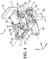
- FIG 4 schematically represents an example of a drive device of a drive module according to the figures 1 And 2 , without representation of the motors of the different kinematic blocks of this drive device.
- the first kinematic block 4 comprises a first motor 41 which rotates a first crank 42 along an axis of rotation ⁇ which is directed along the z axis.
- a connecting rod 43 is fixed to the crank 42 via a double pivot connection 44, the fixing between the connecting rod 43 and the crank 42, at the double pivot connection 44, being offset from the axis of rotation ⁇ of the crank 42 and the first motor 41.
- the connecting rod 43 is fixed at its other end to the key holder 3 via a double pivot connection 44 identical to that providing the connection between the connecting rod 43 and the crank 42.
- the double pivot connections 44 are connections which allow on the one hand rotation along the z axis, and on the other hand rotation along an axis perpendicular to the z axis.
- a rotation of the first motor 41 thus causes a movement of the key holder 3 which is mainly a translation carried out along the x axis.
- the second kinematic block 5 comprises a second motor 51 which rotates a second crank 52 along an axis of rotation ⁇ which is directed along the axis x.
- Two connecting rods 53 are fixed to the crank 52, each of the connecting rods 53 via a double pivot connection 54, the fixing, at this double pivot connection 54, between each of the connecting rods 53 and the crank 52 being offset from the axis of rotation ⁇ of the crank 52 and the second motor 51.
- the connecting rods 53 are each fixed, at their other end, to the key holder 3 via a double pivot connection 54 identical to those providing the connection with the crank 52.
- the connecting rods 53 are parallel and are located on either side of the key holder 3 so as to surround it.
- the connecting rods 53, the axle 56 or the crosspiece 55 of the crank 52 and the key holder 3 together form a parallelogram, which will be described in more detail on the figure 6 , the two connecting rods 53 forming two opposite sides and the crank 52 and the key holder 3 forming the other two opposite sides.
- the crosspiece 55 of the crank 52 is a materialization of this part 55 of the crank 52 which is located between the two double pivot links 54.
- the double pivot links 54 are links which allow on the one hand a rotation along the x axis, and on the other hand a rotation along an axis perpendicular to the x axis.
- a rotation of the second motor 51 thus causes a movement of the key holder 3 which is mainly a translation carried out along the y axis.
- the third kinematic block 6 comprises a third motor 61 which rotates a third crank 62 along an axis of rotation ⁇ which is directed along the y axis.
- Two connecting rods 63 are fixed to the crank 62, each of the connecting rods 63 via a double pivot connection 64, the fixing, at the double connection 64, between each of the connecting rods 63 and the crank 62 being offset from the axis of rotation ⁇ of the crank 62 and the second motor 61.
- the connecting rods 63 are each fixed at their other end to the key holder 3 via a double pivot connection 64 identical to those providing the connection with the crank 62.
- the connecting rods 63 are parallel and are located on either side of the key holder 3 so as to surround it.
- the connecting rods 63, the crank 62 and the key holder 3 together form a parallelogram, which will be described in more detail on the figure 7 , the two connecting rods 63 forming two opposite sides and the crank 62 and the key holder 3 forming the other two opposite sides.
- the double pivot links 64 are links which allow on the one hand a rotation along the y axis, and on the other hand a rotation along an axis perpendicular to the y axis. A rotation of the second motor 61 thus causes a movement of the key holder 3 which is mainly a translation carried out along the z axis.
- the first motor 41, the second motor 51 and the third motor 61 are rotary motors, which makes it possible to simplify the drive device 2.
- the cranks 42, 52 and 62 can be driven in rotation by a linear motor whose connection with each of these cranks 42, 52 and 62 is offset from the axis of rotation of this crank in the same way as the connecting rods on the figures 3 And 4 .
- the connecting rod and crank structure of the kinematic blocks 4, 5 and 6 also makes it possible to simplify the transfer of forces without stressing the engines.
- a simple solution is to have, for each connecting rod, a pivot connection which connects this connecting rod to the frame, the pivot connection being located at the end of the crank which is opposite the end of the connecting rod which is connected to the engine.
- the actuation of a kinematic block does not move the key holder 3 in translation only along a single axis, the movement of the key holder 3 being in fact a translation which comprises a main component along one axis and a secondary component along another axis.
- This secondary component clearly less important than the main component, is a parasitic component which will be compensated.
- the actuation of the second kinematic block 5 with the rotation of the motor 51 causes a translation movement of the key holder 3 with a main component of axis y and a secondary component of axis z.
- the drive module 1 comprises a control unit 7 which controls the operation of the kinematic blocks 4, 5 and 6, the control unit 7 activating the kinematic blocks 4, 5 and 6, so that the movement of the key holder 3 corresponds to the user's command.
- the control unit 7 simultaneously commands the activation of the three kinematic blocks 4, 5 and 6.
- the third kinematic block 6 is activated to give the key holder a translational movement with a main z-axis component and a secondary x-axis component.
- the first kinematic block 4 is activated in order to keep the key holder 3 fixed along the x-axis, the activation of the first kinematic block 4 however creating a secondary y-axis component.
- the second kinematic block 5 is also activated in order to keep the key holder 3 fixed along the y axis, the activation of the second kinematic block 5 however creates a secondary component of the z axis which is taken into account by the control unit 7 for its instruction to the kinematic blocks 4, 5 and 6.
- the three kinematic blocks 4, 5 and 6 are activated simultaneously on the one hand in order to generate all the main components desired by the user and on the other hand in order to compensate for all the parasitic secondary components not desired by the user.
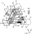
- FIG 5 schematically represents an example of a drive device of a drive module, with representation of the motors of the different kinematic blocks of this drive device, of a possible variant of the figure 3 , a variant in which a kinematic block comprises a platform moved by a linear actuator instead of a connecting rod and crank system.
- one or more kinematic blocks 4, 5 and 6, may not be formed by a connecting rod and crank system.
- the drive device 2 has a third kinematic block 6 which has the function of moving the key holder 3 along the z axis and which comprises a platform 62' which is driven in translation along the z axis by a linear actuator 61'.
- the platform 62' is locked in rotation along any of the three axes, and is also locked for translations along the x axis and the y axis.
- the platform 62' is connected to two connecting rods 63 via double pivot links 64.
- the connecting rods 63 are also connected to the key carrier 3 via double pivot links 64.
- the double pivot bonds 64 are bonds which allow on the one hand a rotation along the y axis, and on the other hand a rotation along an axis perpendicular to the y axis.
- a first parallelogram is formed by the two connecting rods 63, the platform 62' and the key holder 3, in fact more precisely by the two connecting rods 63, the drive crosspiece 65 of the platform 62' and the crosspiece 33 of the key holder 3.
- This first parallelogram blocks the rotational movements of the key holder 3 around the x and z axes.
- the crosspiece 65 of the crank 62 is a materialization of this part 65 of the crank 62 which is located between the two double pivot links 64.
- the second parallelogram is formed by the connecting rods 53, the crank 52 and the key holder 3, in fact more precisely by the two connecting rods 53, the drive crosspiece 55 of the crank 52 and the crosspiece 32 of the key holder 3.
- the actuator 61' is a worm gear motor 69 in the variant illustrated in the figure 5 , however, other types of linear actuators can be used instead.
- the variant illustrated on the figure 5 does not offer the same mechanical simplicity as the variant of Figures 1 to 4 , in particular concerning the positioning of a connection with the platform 62' for the recovery of force without using the actuator 61'.
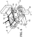
- FIG 6 schematically represents an example of highlighting a first deformable parallelogram of the blocking structure of a first kinematic block of the drive device according to the figure 3 .
- the connecting rods 53, the axis 56 or the crosspiece 55 of the crank 52 and the crosspiece 32 of the key holder 3 together form a first parallelogram P1, the two connecting rods 53 forming two opposite sides and the axis 56 or the crosspiece 55 of the crank 52 and the crosspiece 32 of the key holder 3 forming the other two opposite sides.
- the four sides of the first parallelogram P1 can move relative to each other by pivoting around the double links 54, but always keeping the two connecting rods 53 parallel to each other on the one hand and the axis 56 or the crosspiece 55 of the crank 52 and the crosspiece 32 of the key holder 3 parallel to each other.
- the first parallelogram P1 can therefore be deformed by pivoting its four sides around its four vertices which are the four double links 54, but always remains a parallelogram.
- the first parallelogram P1 was chosen in connection with the axis of rotation ⁇ , but it could have been chosen either in connection with the axis of rotation ⁇ or with the axis of rotation ⁇ .
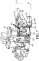
- FIG 7 schematically represents an example of highlighting a second deformable parallelogram of the blocking structure of a second kinematic block of the drive device according to the figures 1 And 2 .
- the connecting rods 63, the axis 66 or the crosspiece 65 of the crank 52 and the crosspiece 33 of the key holder 3 together form a second parallelogram P2, the two connecting rods 63 forming two opposite sides and the axis 66 or the crosspiece 65 of the crank 62 and the crosspiece 33 of the key holder 3 forming the other two opposite sides.
- the four sides of the second parallelogram P2 can move relative to each other by pivoting around the double links 64, but always keeping the two connecting rods 63 parallel to each other on the one hand and the axis 66 or the crosspiece 65 of the crank 62 and the crosspiece 33 of the key holder 3 parallel to each other.
- the second parallelogram P2 can therefore be deformed by pivoting its four sides around its four vertices which are the four double links 64, but always remains a parallelogram.
- the second parallelogram P2 was chosen in connection with the axis of rotation ⁇ , but it could have been chosen either in connection with the axis of rotation ⁇ or with the axis of rotation ⁇ .
- each parallelogram, P1 or P2 blocks two axes of rotation of the key holder 3, the three axes of rotation being blocked by adding the two parallelograms.
- the first parallelogram P1 which is formed by the connecting rods 53, the crank 52 and the crosspiece 32 of the key holder 3 blocks the rotations of said key holder 3 along the y and z axes.
- the crosspiece 32 of the key holder 3 is only a materialization of a part of the key holder 3 connecting the two double pivot links 54. Indeed, the key holder 3 is kept parallel to the crank 52, and since the crank 52 is only movable in rotation about the ⁇ axis (and therefore the x axis), the rotational movements of the key holder 3 about the y and z axes are blocked.
- the second parallelogram P2 which is formed by the connecting rods 63, the crank 63 and the crosspiece 33 of the probe holder 3 blocks the rotations of said probe holder 3 along the x and z axes.
- the crosspiece 33 of the probe holder 3 is only a materialization of a part of the probe holder 3 connecting the two double pivot links 64. Indeed, the probe holder 3 is kept parallel to the crank 62, and since the crank 62 is only mobile in rotation about the axis ⁇ (and therefore the y axis), the rotational movements of the probe holder 3 about the x and z axes are blocked.
- the second parallelogram P2 is shown in front of the connecting rod 53 of the second kinematic block while in reality, it is behind this connecting rod 53, since in fact, the four vertices of the second parallelogram P2 are the four double links 64.
- the structure does not include a third parallelogram, because the use of a single connecting rod 43 at the level of the axis of rotation ⁇ makes it possible to simplify the structure, the three axes of rotation x, y and z, being already blocked by the two parallelograms P1 and P2.
Landscapes
- Health & Medical Sciences (AREA)
- Life Sciences & Earth Sciences (AREA)
- Engineering & Computer Science (AREA)
- Surgery (AREA)
- Public Health (AREA)
- Animal Behavior & Ethology (AREA)
- Biomedical Technology (AREA)
- Heart & Thoracic Surgery (AREA)
- Veterinary Medicine (AREA)
- General Health & Medical Sciences (AREA)
- Medical Informatics (AREA)
- Molecular Biology (AREA)
- Nuclear Medicine, Radiotherapy & Molecular Imaging (AREA)
- Robotics (AREA)
- Biophysics (AREA)
- Pulmonology (AREA)
- Anesthesiology (AREA)
- Hematology (AREA)
- Manipulator (AREA)
Claims (11)
- Antriebsmodul für ein langgestrecktes, flexibles medizinisches Instrument eines Katheterroboters, umfassend:> wenigstens zwei Antriebsvorrichtungen (2), die jeweils zwei gegenüberliegende Tastenhalter (3) tragen, die jeweils dazu bestimmt sind, zwei Tasten aufzunehmen, die, indem sie sich einander annähern, das längliche flexible medizinische Instrument umschließen, um es anschließend in Translation und/oder Rotation anzutreiben,> wobei jede Antriebsvorrichtung (2) selbsttragend ist und drei Antriebsblöcke (4, 5, 6) umfasst, die voneinander unabhängig sind und den Tastenhalter (3) jeweils in den drei orthogonalen Raumrichtungen (x, y, z) translatorisch antreiben, welche jeweils ihren Antriebsmotor (41, 51, 61) umfassen, wobei wenigstens zwei Antriebsblöcke (5, 6) eine Struktur zur Blockierung der Rotationsbewegungen des Tastenhalters (3) aufweisen:∘ wobei eine selbsttragende Antriebseinheit eine Antriebseinheit ist, deren Struktur selbst sicherstellt, dass der Tastenhalter ohne das Vorhandensein eines zusätzlichen Stützelementes in Position gehalten wird,∘ wobei ein von anderen Antriebsblöcken unabhängiger Antriebsblock ein Antriebsblock ist, der nur sein eigenes Gewicht trägt, ohne auch das Gewicht eines anderen Antriebsblocks zu tragen,∘ wobei eine Blockierstruktur umfasst:▪ eine Antriebstraverse (55, 65), die von dem Antriebsmotor (51, 61) angetrieben wird,▪ eine Traverse (32, 33) des Tastenhalters (3), die starr mit dem Tastenhalter (3) verbunden ist und von der Antriebstraverse (55, 65) angetrieben wird,▪ zwei Pleuelstangen (53, 63), die jeweils verbunden sind:• einerseits durch eines ihrer Enden mit zwei voneinander entfernten Schwenkpunkten (54, 64) der Antriebstraverse (55, 65),• andererseits mit dem anderen ihrer Enden an zwei voneinander entfernten Schwenkpunkten (54, 64) der Traverse (32, 33) des Tastenhalters (3),▪ wobei die Antriebstraverse (55, 65), die Traverse (32, 33) des Tastenhalters (3) und die beiden Pleuelstangen (53, 63) zusammen ein Parallelogramm (P1, P2) bilden, das an seinen vier Eckpunkten, die die vier Schwenkpunkte (54, 64) sind, verformbar ist.
- Antriebsmodul nach Anspruch 1, dadurch gekennzeichnet, dass die beiden Pleuelstangen (53, 63) parallel zueinander sind.
- Antriebsmodul nach einem der vorhergehenden Ansprüche, dadurch gekennzeichnet, dass bei wenigstens einem Antriebsblock (5, 6), der eine Blockierstruktur aufweist:➢ die Blockierstruktur des Antriebsblocks (5, 6) ferner eine Kurbel (52, 62) umfasst, die durch den Antriebsmotor (51, 61) um ihre Achse zur Rotation angetrieben wird,➢ die Antriebstraverse (55, 65) eine Längsachse aufweist, die sich zwischen ihren beiden Schwenkpunkten (54, 64) erstreckt,➢ wobei die Rotationsachse der Kurbel (52, 62) parallel zu der Längsachse der Antriebstraverse (55, 65) ist und bleibt,➢ wobei der Zwischenachsenabstand, d.h. der Abstand zwischen der Rotationsachse der Kurbel (52, 62) und der Längsachse der Antriebstraverse (55, 65), konstant ist und bleibt, so dass die Rotation der Kurbel (52, 62) eine Rotation der Längsachse der Antriebstraverse (55, 65) bewirkt.
- Antriebsmodul nach Anspruch 3, dadurch gekennzeichnet, dass bei wenigstens zwei Antriebsblöcken (5, 6), die eine Blockierstruktur aufweisen, bei jedem dieser zwei Antriebsblöcke (5, 6):> die Blockierstruktur des Antriebsblocks (5, 6) ferner eine Kurbel (52, 62) umfasst, die durch den Antriebsmotor (51, 61) um ihre Achse zur Rotation angetrieben wird,> die Antriebstraverse (55, 65) eine Längsachse aufweist, die sich zwischen ihren beiden Schwenkpunkten (54, 64) erstreckt,> wobei die Rotationsachse der Kurbel (52, 62) parallel zu der Längsachse der Antriebstraverse (55, 65) ist und bleibt,➢ wobei der Zwischenachsabstand, d. h. der Abstand zwischen der Rotationsachse der Kurbel (52, 62) und der Längsachse der Antriebstraverse (55, 65), konstant ist und bleibt, so dass die Rotation der Kurbel (52, 62) eine Rotation der Längsachse der Antriebstraverse (55, 65) bewirkt.
- Antriebsmodul nach Anspruch 4, dadurch gekennzeichnet, dass nur zwei Antriebsblöcke (5, 6) pro Antriebsvorrichtung (2) eine Blockierstruktur aufweisen.
- Antriebsmodul nach Anspruch 5, dadurch gekennzeichnet, dass bei dem dritten Antriebsblock (4), der keine Blockierstruktur aufweist, die Struktur des Antriebsblocks (4) umfasst:➢ eine Antriebstraverse, die von dem Antriebsmotor (41) angetrieben wird,➢ eine Traverse des Tastenhalters (3), die starr mit dem Tastenhalter (3) verbunden ist und von der Antriebstraverse angetrieben wird,➢ eine einzelne Pleuelstange (43), die jeweils verbunden ist:∘ einerseits, durch eines ihrer Enden, mit einem Schwenkpunkt (44) der Antriebstraverse,∘ andererseits mit ihrem anderen Ende mit einem Schwenkpunkt (44) der Traverse des Tastenhalters (3).
- Antriebsmodul nach Anspruch 6, dadurch gekennzeichnet, dass bei dem dritten Antriebsblock (4), der keine Blockierstruktur aufweist:➢ die Struktur des Antriebsblocks (4) ferner eine Kurbel (42) umfasst, die von dem Antriebsmotor (41) um ihre Achse zur rotation angetrieben wird,➢ wobei die Antriebstraverse eine Längsachse aufweist,➢ wobei die Rotationsachse der Kurbel (42) parallel zur Längsachse der Antriebstraverse ist und bleibt,➢ wobei der Zwischenachsabstand, d. h. der Abstand zwischen der Rotationsachse der Kurbel (42) und der Längsachse der Antriebstraverse, konstant ist und bleibt, so dass die Rotation der Kurbel (42) eine Rotation der Längsachse der Antriebstraverse bewirkt.
- Antriebsmodul nach einem der vorhergehenden Ansprüche, dadurch gekennzeichnet, dass bei einem Antriebsblock (4, 5, 6) oder mehreren Antriebsblöcken (4, 5, 6) oder bei allen Antriebsblöcke (4, 5, 6) der oder die Antriebsmotoren (41, 51, 61) Drehmotoren sind, die eine Kurbel (42, 52, 62), die starr mit der Antriebstraverse (55, 65) verbunden ist, zur Rotation antreiben.
- Antriebsmodul nach einem der vorhergehenden Ansprüche, dadurch gekennzeichnet, dass bei einem Antriebsblock (4, 5, 6) oder mehreren Antriebsblöcken (4, 5, 6) oder bei allen Antriebsblöcken (4, 5, 6) der oder die Antriebsmotoren (41, 51, 61) Rotationsmotoren sind, die eine Schnecke (69) zur Rotation antreiben, um die Antriebstraverse (55, 65) zur Translation anzutreiben.
- Antriebsmodul nach einem der vorhergehenden Ansprüche, dadurch gekennzeichnet, dass bei jeder Antriebsvorrichtung (2):➢ bei jedem der drei Antriebsblöcke (4, 5, 6) der Antriebsvorrichtung (2):∘ der Antriebsblock (4, 5, 6) den Tastenhalter (3) antreibt:▪ gemäß einer translatorischen Hauptkomponente entlang einer Hauptrichtung, wobei die Hauptrichtung bei jedem der drei Antriebsblöcke (4, 5, 6) unterschiedlich ist,▪ und gemäß einer parasitären Translationskomponente entlang einer anderen Richtung, wobei die andere Richtung bei jedem der drei Antriebsblöcke (4, 5, 6) unterschiedlich ist,➢ jeder der drei Antriebsblöcke (4, 5, 6) der Antriebsvorrichtung (2) in seiner Haupttranslationskomponente entlang seiner Hauptrichtung eine Kompensation der parasitären Translationskomponente eines der anderen Antriebsblöcke (4, 5, 6) entlang dieser Hauptrichtung integriert.
- Antriebsmodul nach einem der vorhergehenden Ansprüche, dadurch gekennzeichnet, dass die Schwenkpunkte (54, 64) Gelenke sind, die in zwei Freiheitsgraden schwenkbar sind.
Applications Claiming Priority (2)
| Application Number | Priority Date | Filing Date | Title |
|---|---|---|---|
| FR2014222A FR3118407B1 (fr) | 2020-12-29 | 2020-12-29 | Module d’entrainement d’instrument medical souple allonge de robot catheter |
| PCT/EP2021/087255 WO2022144267A1 (fr) | 2020-12-29 | 2021-12-22 | Module d'entrainement d'instrument medical souple allonge de robot catheter |
Publications (3)
| Publication Number | Publication Date |
|---|---|
| EP4271309A1 EP4271309A1 (de) | 2023-11-08 |
| EP4271309B1 true EP4271309B1 (de) | 2024-10-16 |
| EP4271309C0 EP4271309C0 (de) | 2024-10-16 |
Family
ID=76920807
Family Applications (1)
| Application Number | Title | Priority Date | Filing Date |
|---|---|---|---|
| EP21844684.7A Active EP4271309B1 (de) | 2020-12-29 | 2021-12-22 | Antriebsmodul einer länglichen flexiblen medizinischen vorrichtung eines katheterroboters |
Country Status (7)
| Country | Link |
|---|---|
| US (1) | US20240058583A1 (de) |
| EP (1) | EP4271309B1 (de) |
| JP (1) | JP2024501334A (de) |
| KR (1) | KR20230125214A (de) |
| CN (1) | CN116744868A (de) |
| FR (1) | FR3118407B1 (de) |
| WO (1) | WO2022144267A1 (de) |
Families Citing this family (5)
| Publication number | Priority date | Publication date | Assignee | Title |
|---|---|---|---|---|
| FR3143964A1 (fr) * | 2022-12-23 | 2024-06-28 | Robocath | Module robotise de catheter pour la translation et la rotation d’un instrument medical souple allonge |
| FR3143965A1 (fr) | 2022-12-23 | 2024-06-28 | Robocath | Cassette pour un module motorisé d’un système robotisé de manipulation d’un dispositif médical tel qu’un cathéter |
| FR3143966A1 (fr) | 2022-12-27 | 2024-06-28 | Robocath | Commande d’un actionneur de système robotisé pour l’entraînement d’un instrument médical souple allongé |
| KR20250159990A (ko) * | 2024-05-03 | 2025-11-11 | 큐렉소 주식회사 | 다자유도 외과적 수술 장치 및 구동 방법 |
| KR20250169917A (ko) * | 2024-05-27 | 2025-12-04 | 큐렉소 주식회사 | 다자유도 외과적 수술 장치 및 구동 방법 |
Family Cites Families (17)
| Publication number | Priority date | Publication date | Assignee | Title |
|---|---|---|---|---|
| CH488003A (de) | 1967-03-08 | 1970-03-31 | Geigy Ag J R | Zusatz zur Verbesserung der Eigenschaften von Schmierölen |
| EP1442720A1 (de) * | 2003-01-31 | 2004-08-04 | Tre Esse Progettazione Biomedica S.r.l | Gerät zum Manövrieren flexibler Katheter im menschlichen kardiovaskulären System |
| JP2014113181A (ja) * | 2012-12-06 | 2014-06-26 | Samsung R&D Institute Japan Co Ltd | 多重構造医療用チューブの自動挿入装置 |
| FR3002851B1 (fr) * | 2013-03-07 | 2015-06-19 | Robocath | Module d'entrainement de systeme de catheterisme robotise. |
| US20140277334A1 (en) * | 2013-03-14 | 2014-09-18 | Hansen Medical, Inc. | Active drives for robotic catheter manipulators |
| US10046140B2 (en) * | 2014-04-21 | 2018-08-14 | Hansen Medical, Inc. | Devices, systems, and methods for controlling active drive systems |
| FR3022147B1 (fr) * | 2014-06-12 | 2016-07-22 | Robocath | Module robotise d'entrainement d'organe medical souple allonge |
| FR3037249A1 (fr) * | 2015-06-12 | 2016-12-16 | Robocath | Procede robotise d'entrainement de catheter et de guide de catheter |
| DE102015115559A1 (de) * | 2015-09-15 | 2017-03-16 | Karl Storz Gmbh & Co. Kg | Manipulationssystem sowie Handhabungsvorrichtung für chirurgische Instrumente |
| JP2017064892A (ja) * | 2015-10-02 | 2017-04-06 | 国立大学法人九州大学 | 球面パラレルリンク |
| FR3044541B1 (fr) * | 2015-12-07 | 2017-12-29 | Robocath | Module robotise d'entrainement d'organe medical souple allonge |
| KR101939256B1 (ko) * | 2017-03-08 | 2019-01-16 | 재단법인 아산사회복지재단 | 카테터 이송 장치 |
| WO2018176457A1 (zh) * | 2017-04-01 | 2018-10-04 | 中国科学院深圳先进技术研究院 | 血管介入手术机器人的导管捻旋装置 |
| DE102017111296B3 (de) * | 2017-05-23 | 2018-08-02 | Medineering Gmbh | Robotischer Manipulator zur Führung eines Endoskops mit Parallelkinematik |
| WO2019036418A1 (en) * | 2017-08-16 | 2019-02-21 | Covidien Lp | END EFFECTOR COMPRISING A WRIST SET AND A MONOPOLAR TOOL FOR ROBOTIC SURGICAL SYSTEMS |
| CN110236680B (zh) * | 2019-07-10 | 2020-07-21 | 北京唯迈医疗设备有限公司 | 一种介入手术机器人往复运动装置 |
| US12150730B2 (en) * | 2020-05-04 | 2024-11-26 | The Regents Of The University Of California | Handheld flexible robotic catheter for endoscopic instrumentation |
-
2020
- 2020-12-29 FR FR2014222A patent/FR3118407B1/fr active Active
-
2021
- 2021-12-22 KR KR1020237022131A patent/KR20230125214A/ko active Pending
- 2021-12-22 US US18/259,386 patent/US20240058583A1/en active Pending
- 2021-12-22 JP JP2023539894A patent/JP2024501334A/ja active Pending
- 2021-12-22 EP EP21844684.7A patent/EP4271309B1/de active Active
- 2021-12-22 WO PCT/EP2021/087255 patent/WO2022144267A1/fr not_active Ceased
- 2021-12-22 CN CN202180089325.XA patent/CN116744868A/zh active Pending
Also Published As
| Publication number | Publication date |
|---|---|
| FR3118407A1 (fr) | 2022-07-01 |
| KR20230125214A (ko) | 2023-08-29 |
| US20240058583A1 (en) | 2024-02-22 |
| FR3118407B1 (fr) | 2023-04-21 |
| CN116744868A (zh) | 2023-09-12 |
| JP2024501334A (ja) | 2024-01-11 |
| WO2022144267A1 (fr) | 2022-07-07 |
| EP4271309A1 (de) | 2023-11-08 |
| EP4271309C0 (de) | 2024-10-16 |
Similar Documents
| Publication | Publication Date | Title |
|---|---|---|
| EP4271309B1 (de) | Antriebsmodul einer länglichen flexiblen medizinischen vorrichtung eines katheterroboters | |
| EP1049950B1 (de) | Vorrichtung zur montage und lagekorrektur eines elementes, wie eines spiegels von einem weltraumteleskop | |
| EP1597017B1 (de) | Vorrichtung zur bewegung und ausrichtung eines objekts im raum und verwendung davon bei schnellbearbeitung | |
| EP3280374B1 (de) | Exoskelett mit einer mechanischen knöchelverbindung mit zwei drehachsen | |
| EP0250470B1 (de) | Einrichtung zum bewegen und positionieren eines gegenstandes im raum | |
| EP2483040B1 (de) | Roboterstruktur oder haptische schnittstellenstruktur mit parallelen armen | |
| EP0871563B1 (de) | Master-slave-handhabungsvorrichtung mit sechs freiheitsgraden | |
| EP1786602A1 (de) | Parallelroboter mit mitteln, um ein in zwei getrennte unterbaugruppen unterteiltes mobiles element in bewegung zu versetzen | |
| EP2643127A1 (de) | Parallelroboter mit zwei freiheitsgraden mit zwei kinematischen ketten mit maximiertefr steifigkeitsbiegung | |
| EP1282485B1 (de) | Steuerarm mit paralleler struktur | |
| EP1292431A1 (de) | Steuerarm mit paralleler struktur | |
| WO2014108424A1 (fr) | Robot manipulateur translationnel pur a trois degres de liberte serie a encombrement reduit | |
| WO1992001963A1 (fr) | Dispositif de support et de positionnement d'un microscope | |
| EP3145680A1 (de) | Gondel für einen parallelen roboter zur steuerung eines objektes | |
| EP3523099B1 (de) | Paralleles roboterhandgelenk mit vier freiheitsgraden | |
| EP1402992A1 (de) | Vorrichtung mit höher Präzision zum Vorgeben oder zum Messen einer Position oder Kraft | |
| EP4034024B1 (de) | Surgery assistance device | |
| WO2003066288A1 (fr) | Dispositif de deplacement spherique d'un element | |
| EP3089913A1 (de) | Segmentierte struktur, insbesondere für einen satellitenantennenreflektor, mit mindestens einer drehbaren und mindestens einer übergreifenden einsatzvorrichtung | |
| WO2009016229A1 (fr) | Dispositif articule a pantographes | |
| FR2950830A1 (fr) | Structure de robot ou d'interface haptique a bras en paralleles | |
| WO2024133273A1 (fr) | Module robotise de catheter pour la translation et la rotation d'un instrument medical souple allonge | |
| WO2006042975A1 (fr) | Dispositif et installation de pliage d'un flan |
Legal Events
| Date | Code | Title | Description |
|---|---|---|---|
| STAA | Information on the status of an ep patent application or granted ep patent |
Free format text: STATUS: UNKNOWN |
|
| STAA | Information on the status of an ep patent application or granted ep patent |
Free format text: STATUS: THE INTERNATIONAL PUBLICATION HAS BEEN MADE |
|
| PUAI | Public reference made under article 153(3) epc to a published international application that has entered the european phase |
Free format text: ORIGINAL CODE: 0009012 |
|
| STAA | Information on the status of an ep patent application or granted ep patent |
Free format text: STATUS: REQUEST FOR EXAMINATION WAS MADE |
|
| 17P | Request for examination filed |
Effective date: 20230629 |
|
| AK | Designated contracting states |
Kind code of ref document: A1 Designated state(s): AL AT BE BG CH CY CZ DE DK EE ES FI FR GB GR HR HU IE IS IT LI LT LU LV MC MK MT NL NO PL PT RO RS SE SI SK SM TR |
|
| DAV | Request for validation of the european patent (deleted) | ||
| DAX | Request for extension of the european patent (deleted) | ||
| GRAP | Despatch of communication of intention to grant a patent |
Free format text: ORIGINAL CODE: EPIDOSNIGR1 |
|
| STAA | Information on the status of an ep patent application or granted ep patent |
Free format text: STATUS: GRANT OF PATENT IS INTENDED |
|
| INTG | Intention to grant announced |
Effective date: 20240513 |
|
| GRAS | Grant fee paid |
Free format text: ORIGINAL CODE: EPIDOSNIGR3 |
|
| GRAA | (expected) grant |
Free format text: ORIGINAL CODE: 0009210 |
|
| STAA | Information on the status of an ep patent application or granted ep patent |
Free format text: STATUS: THE PATENT HAS BEEN GRANTED |
|
| AK | Designated contracting states |
Kind code of ref document: B1 Designated state(s): AL AT BE BG CH CY CZ DE DK EE ES FI FR GB GR HR HU IE IS IT LI LT LU LV MC MK MT NL NO PL PT RO RS SE SI SK SM TR |
|
| REG | Reference to a national code |
Ref country code: GB Ref legal event code: FG4D Free format text: NOT ENGLISH |
|
| REG | Reference to a national code |
Ref country code: CH Ref legal event code: EP |
|
| REG | Reference to a national code |
Ref country code: IE Ref legal event code: FG4D Free format text: LANGUAGE OF EP DOCUMENT: FRENCH |
|
| REG | Reference to a national code |
Ref country code: DE Ref legal event code: R096 Ref document number: 602021020484 Country of ref document: DE |
|
| U01 | Request for unitary effect filed |
Effective date: 20241113 |
|
| U07 | Unitary effect registered |
Designated state(s): AT BE BG DE DK EE FI FR IT LT LU LV MT NL PT RO SE SI Effective date: 20241120 |
|
| U20 | Renewal fee for the european patent with unitary effect paid |
Year of fee payment: 4 Effective date: 20241216 |
|
| PG25 | Lapsed in a contracting state [announced via postgrant information from national office to epo] |
Ref country code: IS Free format text: LAPSE BECAUSE OF FAILURE TO SUBMIT A TRANSLATION OF THE DESCRIPTION OR TO PAY THE FEE WITHIN THE PRESCRIBED TIME-LIMIT Effective date: 20250216 Ref country code: HR Free format text: LAPSE BECAUSE OF FAILURE TO SUBMIT A TRANSLATION OF THE DESCRIPTION OR TO PAY THE FEE WITHIN THE PRESCRIBED TIME-LIMIT Effective date: 20241016 |
|
| PG25 | Lapsed in a contracting state [announced via postgrant information from national office to epo] |
Ref country code: ES Free format text: LAPSE BECAUSE OF FAILURE TO SUBMIT A TRANSLATION OF THE DESCRIPTION OR TO PAY THE FEE WITHIN THE PRESCRIBED TIME-LIMIT Effective date: 20241016 |
|
| PG25 | Lapsed in a contracting state [announced via postgrant information from national office to epo] |
Ref country code: NO Free format text: LAPSE BECAUSE OF FAILURE TO SUBMIT A TRANSLATION OF THE DESCRIPTION OR TO PAY THE FEE WITHIN THE PRESCRIBED TIME-LIMIT Effective date: 20250116 |
|
| PG25 | Lapsed in a contracting state [announced via postgrant information from national office to epo] |
Ref country code: GR Free format text: LAPSE BECAUSE OF FAILURE TO SUBMIT A TRANSLATION OF THE DESCRIPTION OR TO PAY THE FEE WITHIN THE PRESCRIBED TIME-LIMIT Effective date: 20250117 |
|
| PG25 | Lapsed in a contracting state [announced via postgrant information from national office to epo] |
Ref country code: PL Free format text: LAPSE BECAUSE OF FAILURE TO SUBMIT A TRANSLATION OF THE DESCRIPTION OR TO PAY THE FEE WITHIN THE PRESCRIBED TIME-LIMIT Effective date: 20241016 |
|
| PG25 | Lapsed in a contracting state [announced via postgrant information from national office to epo] |
Ref country code: RS Free format text: LAPSE BECAUSE OF FAILURE TO SUBMIT A TRANSLATION OF THE DESCRIPTION OR TO PAY THE FEE WITHIN THE PRESCRIBED TIME-LIMIT Effective date: 20250116 |
|
| PG25 | Lapsed in a contracting state [announced via postgrant information from national office to epo] |
Ref country code: SM Free format text: LAPSE BECAUSE OF FAILURE TO SUBMIT A TRANSLATION OF THE DESCRIPTION OR TO PAY THE FEE WITHIN THE PRESCRIBED TIME-LIMIT Effective date: 20241016 |
|
| PG25 | Lapsed in a contracting state [announced via postgrant information from national office to epo] |
Ref country code: MC Free format text: LAPSE BECAUSE OF FAILURE TO SUBMIT A TRANSLATION OF THE DESCRIPTION OR TO PAY THE FEE WITHIN THE PRESCRIBED TIME-LIMIT Effective date: 20241016 |
|
| PG25 | Lapsed in a contracting state [announced via postgrant information from national office to epo] |
Ref country code: SK Free format text: LAPSE BECAUSE OF FAILURE TO SUBMIT A TRANSLATION OF THE DESCRIPTION OR TO PAY THE FEE WITHIN THE PRESCRIBED TIME-LIMIT Effective date: 20241016 |
|
| PG25 | Lapsed in a contracting state [announced via postgrant information from national office to epo] |
Ref country code: CZ Free format text: LAPSE BECAUSE OF FAILURE TO SUBMIT A TRANSLATION OF THE DESCRIPTION OR TO PAY THE FEE WITHIN THE PRESCRIBED TIME-LIMIT Effective date: 20241016 |
|
| PLBE | No opposition filed within time limit |
Free format text: ORIGINAL CODE: 0009261 |
|
| STAA | Information on the status of an ep patent application or granted ep patent |
Free format text: STATUS: NO OPPOSITION FILED WITHIN TIME LIMIT |
|
| 26N | No opposition filed |
Effective date: 20250717 |
|
| REG | Reference to a national code |
Ref country code: CH Ref legal event code: U11 Free format text: ST27 STATUS EVENT CODE: U-0-0-U10-U11 (AS PROVIDED BY THE NATIONAL OFFICE) Effective date: 20260101 |
|
| PGFP | Annual fee paid to national office [announced via postgrant information from national office to epo] |
Ref country code: GB Payment date: 20251215 Year of fee payment: 5 |
|
| PGFP | Annual fee paid to national office [announced via postgrant information from national office to epo] |
Ref country code: IE Payment date: 20251215 Year of fee payment: 5 |
|
| U20 | Renewal fee for the european patent with unitary effect paid |
Year of fee payment: 5 Effective date: 20251216 |
|
| PGFP | Annual fee paid to national office [announced via postgrant information from national office to epo] |
Ref country code: CH Payment date: 20260101 Year of fee payment: 5 |