EP4271214B1 - Capsules with integrated mouthpieces, heat-not-burn (hnb) aerosol-generating devices, and methods of generating an aerosol - Google Patents
Capsules with integrated mouthpieces, heat-not-burn (hnb) aerosol-generating devices, and methods of generating an aerosol Download PDFInfo
- Publication number
- EP4271214B1 EP4271214B1 EP21827502.2A EP21827502A EP4271214B1 EP 4271214 B1 EP4271214 B1 EP 4271214B1 EP 21827502 A EP21827502 A EP 21827502A EP 4271214 B1 EP4271214 B1 EP 4271214B1
- Authority
- EP
- European Patent Office
- Prior art keywords
- cover
- aerosol
- capsule
- base portion
- heater
- Prior art date
- Legal status (The legal status is an assumption and is not a legal conclusion. Google has not performed a legal analysis and makes no representation as to the accuracy of the status listed.)
- Active
Links
Images


Classifications
-
- A—HUMAN NECESSITIES
- A24—TOBACCO; CIGARS; CIGARETTES; SIMULATED SMOKING DEVICES; SMOKERS' REQUISITES
- A24F—SMOKERS' REQUISITES; MATCH BOXES; SIMULATED SMOKING DEVICES
- A24F40/00—Electrically operated smoking devices; Component parts thereof; Manufacture thereof; Maintenance or testing thereof; Charging means specially adapted therefor
- A24F40/40—Constructional details, e.g. connection of cartridges and battery parts
- A24F40/42—Cartridges or containers for inhalable precursors
-
- A—HUMAN NECESSITIES
- A24—TOBACCO; CIGARS; CIGARETTES; SIMULATED SMOKING DEVICES; SMOKERS' REQUISITES
- A24F—SMOKERS' REQUISITES; MATCH BOXES; SIMULATED SMOKING DEVICES
- A24F40/00—Electrically operated smoking devices; Component parts thereof; Manufacture thereof; Maintenance or testing thereof; Charging means specially adapted therefor
- A24F40/20—Devices using solid inhalable precursors
-
- A—HUMAN NECESSITIES
- A24—TOBACCO; CIGARS; CIGARETTES; SIMULATED SMOKING DEVICES; SMOKERS' REQUISITES
- A24F—SMOKERS' REQUISITES; MATCH BOXES; SIMULATED SMOKING DEVICES
- A24F40/00—Electrically operated smoking devices; Component parts thereof; Manufacture thereof; Maintenance or testing thereof; Charging means specially adapted therefor
- A24F40/40—Constructional details, e.g. connection of cartridges and battery parts
- A24F40/46—Shape or structure of electric heating means
- A24F40/465—Shape or structure of electric heating means specially adapted for induction heating
-
- A—HUMAN NECESSITIES
- A61—MEDICAL OR VETERINARY SCIENCE; HYGIENE
- A61K—PREPARATIONS FOR MEDICAL, DENTAL OR TOILETRY PURPOSES
- A61K36/00—Medicinal preparations of undetermined constitution containing material from algae, lichens, fungi or plants, or derivatives thereof, e.g. traditional herbal medicines
- A61K36/18—Magnoliophyta (angiosperms)
- A61K36/185—Magnoliopsida (dicotyledons)
- A61K36/81—Solanaceae (Potato family), e.g. tobacco, nightshade, tomato, belladonna, capsicum or jimsonweed
-
- A—HUMAN NECESSITIES
- A61—MEDICAL OR VETERINARY SCIENCE; HYGIENE
- A61M—DEVICES FOR INTRODUCING MEDIA INTO, OR ONTO, THE BODY; DEVICES FOR TRANSDUCING BODY MEDIA OR FOR TAKING MEDIA FROM THE BODY; DEVICES FOR PRODUCING OR ENDING SLEEP OR STUPOR
- A61M11/00—Sprayers or atomisers specially adapted for therapeutic purposes
- A61M11/04—Sprayers or atomisers specially adapted for therapeutic purposes operated by the vapour pressure of the liquid to be sprayed or atomised
- A61M11/041—Sprayers or atomisers specially adapted for therapeutic purposes operated by the vapour pressure of the liquid to be sprayed or atomised using heaters
- A61M11/042—Sprayers or atomisers specially adapted for therapeutic purposes operated by the vapour pressure of the liquid to be sprayed or atomised using heaters electrical
-
- A—HUMAN NECESSITIES
- A61—MEDICAL OR VETERINARY SCIENCE; HYGIENE
- A61M—DEVICES FOR INTRODUCING MEDIA INTO, OR ONTO, THE BODY; DEVICES FOR TRANSDUCING BODY MEDIA OR FOR TAKING MEDIA FROM THE BODY; DEVICES FOR PRODUCING OR ENDING SLEEP OR STUPOR
- A61M15/00—Inhalators
- A61M15/06—Inhaling appliances shaped like cigars, cigarettes or pipes
-
- A—HUMAN NECESSITIES
- A61—MEDICAL OR VETERINARY SCIENCE; HYGIENE
- A61M—DEVICES FOR INTRODUCING MEDIA INTO, OR ONTO, THE BODY; DEVICES FOR TRANSDUCING BODY MEDIA OR FOR TAKING MEDIA FROM THE BODY; DEVICES FOR PRODUCING OR ENDING SLEEP OR STUPOR
- A61M2205/00—General characteristics of the apparatus
- A61M2205/82—Internal energy supply devices
- A61M2205/8206—Internal energy supply devices battery-operated
Definitions
- the present disclosure relates to capsules, heat-not-burn (HNB) aerosol-generating devices, and methods of generating an aerosol without involving a substantial pyrolysis of the aerosol-forming substrate.
- HNB heat-not-burn
- Some electronic devices are configured to heat a plant material to a temperature that is sufficient to release constituents of the plant material while keeping the temperature below a combustion point of the plant material so as to avoid any substantial pyrolysis of the plant material.
- Such devices may be referred to as aerosol-generating devices (e.g., heat-not-burn aerosol-generating devices), and the plant material heated may be tobacco.
- the plant material may be introduced directly into a heating chamber of an aerosol-generating device.
- the plant material may be pre-packaged in individual containers to facilitate insertion and removal from an aerosol-generating device.
- EP 3 166 426 B1 describes an electrically operated aerosol-generating system comprising an aerosol-generating device, and first and second removable aerosol-forming cartridges each comprising a resistive heater.
- the first removable aerosol-forming cartridge comprises a first aerosol-forming substrate requiring a first heating profile and the second removable aerosol-forming cartridge comprises a second aerosol-forming substrate requiring a second heating profile.
- the aerosol-generating device comprises a main body defining a cavity and at least one opening for removably receiving one of the first and second aerosol-forming cartridges in the cavity.
- the aerosol-generating device also comprises an electrical power supply and a control unit for controlling a supply of electrical current from the electrical power supply to the electric heater.
- the control unit is arranged to detect whether the first or second aerosol-forming cartridge has been received within the cavity based upon the resistive load of the respective resistive heater.
- the control unit is further arranged to control the supply of electrical current to the at least one electric heater according to either the first or the second heating profile in response to the detected aerosol-forming cartridge.
- US 2016/143358 A1 describes a heating assembly for an electronic cigarette vaporizer.
- the heating assembly includes: a pair of vaporizer shields, certain heating elements, an e-liquid medium, a pair of vapor guides, and a vaporizing chamber side cover. Vaporizer shields are disposed on a heating element base. An e-liquid medium opening is defined between the vaporizer shields.
- Each of the heating elements has a first terminal and a second terminal.
- the e-liquid medium is vertically positioned in the e-liquid medium opening.
- the e-liquid medium has certain heating element grooves for installing the heating elements.
- the vapor guides are placed between vaporizer shields and the e-liquid medium.
- the vaporizing chamber side cover is configured to surround the first vaporizer shield and the second vaporizer shield, the e-liquid medium.
- the vaporizing chamber side cover defines two e-liquid conduit openings, one on each side of the e-liquid medium.
- US 2018/116291 A1 describes vaporizer apparatuses, including cartridges and vaporizers having fluid-level windows through the body of the vaporizer allowing visualization into the cartridge and the vaporizer; the cartridge is magnetically coupled to the vaporizer.
- the present invention as defined in claim 1 relates to a capsule for an aerosol-generating device.
- a capsule for a heat-not-burn (HNB) aerosol-generating device may include a base portion, a first cover, a second cover, an aerosol-forming substrate, and a heater.
- the base portion includes an engagement assembly.
- the first cover is engaged with the base portion via the engagement assembly.
- the first cover includes a first interior surface and a first exterior surface.
- the first interior surface defines a first recess.
- the second cover is engaged with the base portion and the first cover via the engagement assembly.
- the second cover includes a second interior surface and a second exterior surface.
- the second interior surface defines a second recess.
- the first cover is aligned with the second cover such that the first recess and the second recess collectively form a chamber.
- the aerosol-forming substrate is within the chamber.
- the heater is configured to heat the aerosol-forming substrate to generate an aerosol.
- the heater includes a first end section, an intermediate section, and a second end section. The heater extends from the base portion such that the intermediate section is in the chamber.
- the aerosol-generating device may include a capsule and a device body.
- the capsule includes a housing containing an aerosol-forming substrate and a heater configured to heat the aerosol-forming substrate.
- the housing includes a base portion, a first cover, and a second cover. The first cover and the second cover jointly define therebetween a chamber, an aerosol channel, and an aerosol outlet.
- the aerosol-forming substrate is disposed in the chamber.
- the heater is supported by the base portion and extends into the chamber.
- the device body is configured to connect to the capsule.
- the device body includes a power source configured to supply an electric current to the heater.
- At least one embodiment relates to a method of generating an aerosol.
- the method may include supplying an electric current to a capsule including a housing containing an aerosol-forming substrate and a heater such that the heater undergoes resistive heating.
- the housing includes a base portion, a first cover, and a second cover.
- the first cover and the second cover jointly define therebetween a chamber, an aerosol channel, and an aerosol outlet.
- the aerosol-forming substrate is disposed in the chamber.
- the heater is supported by the base portion and extends into the chamber.
- the method may optionally include drawing the aerosol generated by the resistive heating from the chamber and through the aerosol channel and the aerosol outlet.
- first, second, third, etc. may be used herein to describe various elements, regions, layers and/or sections, these elements, regions, layers, and/or sections should not be limited by these terms. These terms are only used to distinguish one element, region, layer, or section from another region, layer, or section. Thus, a first element, region, layer, or section discussed below could be termed a second element, region, layer, or section without departing from the teachings of example embodiments.
- spatially relative terms e.g., "beneath,” “below,” “lower,” “above,” “upper,” and the like
- the spatially relative terms are intended to encompass different orientations of the device in use or operation in addition to the orientation depicted in the figures. For example, if the device in the figures is turned over, elements described as “below” or “beneath” other elements or features would then be oriented “above” the other elements or features. Thus, the term “below” may encompass both an orientation of above and below.
- the device may be otherwise oriented (rotated 90 degrees or at other orientations) and the spatially relative descriptors used herein interpreted accordingly.
- the processing circuitry may be hardware including logic circuits; a hardware/software combination such as a processor executing software; or a combination thereof.
- the processing circuitry more specifically may include, but is not limited to, a central processing unit (CPU) , an arithmetic logic unit (ALU), a digital signal processor, a microcomputer, a field programmable gate array (FPGA), a System-on-Chip (SoC), a programmable logic unit, a microprocessor, application-specific integrated circuit (ASIC), etc.
- CPU central processing unit
- ALU arithmetic logic unit
- FPGA field programmable gate array
- SoC System-on-Chip
- ASIC application-specific integrated circuit
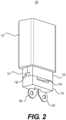
- FIG. 1 is a first perspective view of a capsule for an aerosol-generating device according to an example embodiment.
- FIG. 2 is a second perspective view of the capsule of FIG. 1 .
- a capsule 100 includes a housing configured to hold an aerosol-forming substrate and to accommodate a heater configured to heat the aerosol-forming substrate to generate an aerosol.
- the housing of the capsule 100 includes a base portion 130, a first cover 110, and a second cover 120.
- the base portion 130 includes an engagement assembly 136 configured to facilitate a connection with the first cover 110 and the second cover 120.
- the first cover 110 and the second cover 120 are configured to be received by an end cap 170.
- the end cap 170 defines at least one aerosol outlet 174.
- the end cap 170 may be regarded as a mouthpiece that is integrated with the housing to produce a capsule 100 that is of a 4-piece construction.
- the base portion 130 and the first cover 110 when connected, define a first air inlet 152 therebetween.
- the base portion 130 and the second cover 120 when connected, define a second air inlet 154 therebetween.
- the first air inlet 152 and the second air inlet 154 are in fluidic communication with the aerosol outlets 174.
- a heater is configured to extend through the base portion 130 such that the first end section 142 and the second end section 146 are visible while the intermediate section of the heater is hidden from view when the capsule 100 is assembled. The heater will be discussed in further detail in connection with subsequent drawings.
- FIG. 3 is a partially exploded view of the capsule of FIG. 1 .
- FIG. 4 is a partially exploded view of the capsule of FIG. 2 .
- the first cover 110 and the second cover 120 are configured to engage with each other and with the base portion 130 such that their adjacent surfaces are substantially flush.
- the main external surface of the first cover 110 may be flush with the front surface of the base portion 130 (e.g., FIG. 3 ).
- the main external surface of the second cover 120 may be flush with the rear surface of the base portion 130 (e.g., FIG. 4 ).
- the opposing side surfaces of the base portion 130 may be flush with the adjoining side surfaces of the first cover 110 and the second cover 120.
- the downstream end surface of the first cover 110 may be flush with the downstream end surface of the second cover 120.
- the resulting structure e.g., housing
- the resulting structure may have a form resembling a cuboid with a front face, an opposing rear face, a first side face, an opposing second side face, an upstream end face, and an opposing downstream end face.
- upstream and, conversely, “downstream”
- proximal and, conversely, “distal”
- aerosol generation is in relation to an adult operator of the device during aerosol generation.
- the resulting structure (from the coupling of the first cover 110, the second cover 120, and the base portion 130) may have a rectangular cross-section.
- the cuboid form of the resulting structure may have a square cross-section.
- example embodiments are not limited thereto.
- the resulting structure may have a form resembling a cylinder (e.g., elliptic cylinder, circular cylinder).
- a cylinder e.g., elliptic cylinder, circular cylinder.
- the resulting structure may have an elliptical cross-section.
- the resulting structure may have a circular cross-section.
- the main external surface of the first cover 110 and the front surface of the base portion 130 may be jointly regarded as the front face (e.g., which defines the first air inlet 152).
- the main external surface of the second cover 120 and the rear surface of the base portion 130 may be jointly regarded as the opposing rear face (e.g., which defines the second air inlet 154).
- the opposing side surfaces of the base portion 130 and the corresponding side surfaces of the first cover 110 and the second cover 120 may be jointly regarded as the first side face and the opposing second side face of the housing.
- the underside or bottom of the base portion 130 may be regarded as the upstream end face (e.g., from which the first end section 142 and the second end section 146 of the heater extend).
- the downstream end surface of the first cover 110 and the corresponding downstream end surface of the second cover 120 may be jointly regarded as the downstream end face of the housing.
- the downstream end face of the housing defines a passageway 166.
- the passageway 166 is in fluidic communication with the first air inlet 152 and the second air inlet 154.
- the first air inlet 152, the second air inlet 154, and the passageway 166 are dimensioned so as to be small enough to retain the aerosol-forming substrate within the housing while large enough to permit an adequate inflow of air via the first air inlet 152 and the second air inlet 154 and to permit an adequate outflow of aerosol via the passageway 166.
- the end cap 170 may define four aerosol outlets 174, it should be understood that example embodiments are not limited thereto.
- the end cap 170 may define less than four (e.g., 1-3) aerosol outlets 174.
- the end cap 170 may define more than four (e.g., 5-8) aerosol outlets 174.
- the form of the end cap 170 may correspond to the form of the housing formed by the first cover 110, the second cover 120, and the base portion 130 (e.g., cuboid form for both the end cap 170 and the housing).
- the form of the end cap 170 may differ from the form of the housing formed by the first cover 110, the second cover 120, and the base portion 130 (e.g., cuboid form for the end cap 170 and cylindrical form for the housing or vice versa).
- the aerosol outlets 174 may be arranged in a linear/sequential manner, in a radial manner, or in an array of rows and columns depending on the number of aerosol outlets 174 as well as the form and available space of the end cap 170.
- the shape of each of the aerosol outlets 174 may be circular, elongated (e.g., elliptical), polygonal (e.g., rounded rectangular), or of another suitable shape.
- the end cap 170 defines a cavity 172 configured to receive the first cover 110 and the second cover 120 of the housing during the assembly of the capsule 100.
- the main external surfaces of the first cover 110 and the second cover 120 will interface with the corresponding main internal surfaces of the end cap 170.
- the external side surfaces of the first cover 110 and the second cover 120 may interface with the corresponding internal side surfaces of the end cap 170.
- Such interfacial engagements may be via an interference fit (which may also be referred to as a press fit or friction fit).
- the attachment technique may include an adhesive (e.g., tape, glue) that has been deemed food-safe or otherwise acceptable by a regulatory authority.
- the attachment technique may involve ultrasonic welding.
- FIG. 5 is a further exploded view of the capsule of FIG. 3 .
- FIG. 6 is a further exploded view of the capsule of FIG. 4 .
- the first cover 110 defines a first notch 112, a first recess 114, and a first downstream rim 116.
- the second cover 120 defines a second notch 122, a second recess 124, and a second downstream rim 126.
- the first cover 110 and the second cover 120 may be identical parts. In such instances, orienting the first cover 110 and the second cover 120 to face each other for mating with the base portion 130 will result in a complementary arrangement. As a result, one part may be used interchangeably as the first cover 110 or the second cover 120, thus simplifying the method of manufacturing.
- the first notch 112 may be defined as a pair of notches at the upstream corners of the first cover 110, wherein each notch may be adjacent to/exposed by the upstream end surface of the first cover 110 and also adjacent to/exposed by a side surface of the first cover 110 (e.g., FIG. 6 ).
- the second notch 122 may be defined as a pair of notches at the upstream corners of the second cover 120, wherein each notch may be adjacent to/exposed by the upstream end surface of the second cover 120 and also adjacent to/exposed by a side surface of the second cover 120 (e.g., FIG. 5 ).
- the first notch 112 and the second notch 122 collectively form a T-shaped notch configured to mate with the engagement assembly 136 when the first cover 110 and the second cover 120 are coupled with the base portion 130.
- first recess 114 of the first cover 110 and the second recess 124 of the second cover 120 collectively form a chamber (e.g., chamber 164 in FIG. 7 ) configured to accommodate the intermediate section 144 of the heater 140 when the first cover 110 and the second cover 120 are coupled with the base portion 130.
- a first aerosol-forming substrate 160a and a second aerosol-forming substrate 160b may also be accommodated within the chamber so as to be in thermal contact with the intermediate section 144 of the heater 140 when the capsule 100 is assembled.
- each of the first aerosol-forming substrate 160a and the second aerosol-forming substrate 160b may be in a consolidated form (e.g., sheet, pallet, tablet) that is configured to maintain its shape so as to allow the first aerosol-forming substrate 160a and the second aerosol-forming substrate 160b to be placed in a unified manner within the first recess 114 of the first cover 110 and the second recess 124 of the second cover 120, respectively.
- a consolidated form e.g., sheet, pallet, tablet
- the first aerosol-forming substrate 160a may be disposed on one side of the intermediate section 144 of the heater 140 (e.g., side facing the first cover 110), while the second aerosol-forming substrate 160b may be disposed on the other side of the intermediate section 144 of the heater 140 (e.g., side facing the second cover 120) so as to substantially fill the first recess 114 of the first cover 110 and the second recess 124 of the second cover 120, respectively, thereby sandwiching/embedding the intermediate section 144 of the heater 140 in between.
- first aerosol-forming substrate 160a and the second aerosol-forming substrate 160b may be in a loose form (e.g., particles, fibers, grounds, fragments, shreds) that does not have a set shape but rather is configured to take on the shape of the first recess 114 of the first cover 110 and/or the second recess 124 of the second cover 120 when introduced.
- a loose form e.g., particles, fibers, grounds, fragments, shreds
- an aerosol-forming substrate is a material or combination of materials that may yield an aerosol.
- An aerosol relates to the matter generated or output by the devices disclosed, claimed, and equivalents thereof.
- the material may include a compound (e.g., nicotine, cannabinoid), wherein an aerosol including the compound is produced when the material is heated.
- the heating may be below the combustion temperature so as to produce an aerosol without involving a substantial pyrolysis of the aerosol-forming substrate or the substantial generation of combustion byproducts (if any).
- pyrolysis does not occur during the heating and resulting production of aerosol.
- there may be some pyrolysis and combustion byproducts but the extent may be considered relatively minor and/or merely incidental.
- the aerosol-forming substrate may be a fibrous material.
- the fibrous material may be a botanical material.
- the fibrous material is configured to release a compound when heated.
- the compound may be a naturally occurring constituent of the fibrous material.
- the fibrous material may be plant material such as tobacco, and the compound released may be nicotine.
- tobacco includes any tobacco plant material including tobacco leaf, tobacco plug, reconstituted tobacco, compressed tobacco, shaped tobacco, or powder tobacco, and combinations thereof from one or more species of tobacco plants, such as Nicotiana rustica and Nicotiana tabacum.
- the tobacco material may include material from any member of the genus Nicotiana.
- the tobacco material may include a blend of two or more different tobacco varieties. Examples of suitable types of tobacco materials that may be used include, but are not limited to, flue-cured tobacco, Burley tobacco, Dark tobacco, Maryland tobacco, Oriental tobacco, rare tobacco, specialty tobacco, blends thereof, and the like.
- the tobacco material may be provided in any suitable form, including, but not limited to, tobacco lamina, processed tobacco materials, such as volume expanded or puffed tobacco, processed tobacco stems, such as cut-rolled or cut-puffed stems, reconstituted tobacco materials, blends thereof, and the like.
- the tobacco material is in the form of a substantially dry tobacco mass.
- the tobacco material may be mixed and/or combined with at least one of propylene glycol, glycerin, sub-combinations thereof, or combinations thereof.
- the compound may also be a naturally occurring constituent of a medicinal plant that has a medically-accepted therapeutic effect.
- the medicinal plant may be a cannabis plant, and the compound may be a cannabinoid.
- Cannabinoids interact with receptors in the body to produce a wide range of effects.
- cannabinoids have been used for a variety of medicinal purposes (e.g., treatment of pain, nausea, epilepsy, psychiatric disorders).
- the fibrous material may include the leaf and/or flower material from one or more species of cannabis plants such as Cannabis sativa, Cannabis indica, and Cannabis ruderalis. In some instances, the fibrous material is a mixture of 60-80% (e.g., 70%) Cannabis sativa and 20-40% (e.g., 30%) Cannabis indica.
- cannabinoids examples include tetrahydrocannabinolic acid (THCA), tetrahydrocannabinol (THC), cannabidiolic acid (CBDA), cannabidiol (CBD), cannabinol (CBN), cannabicyclol (CBL), cannabichromene (CBC), and cannabigerol (CBG).
- THCA tetrahydrocannabinolic acid
- THC tetrahydrocannabinol
- CBDA cannabidiolic acid
- CBD cannabigerol
- Tetrahydrocannabinolic acid (THCA) and cannabidiolic acid (CBDA) may be converted to tetrahydrocannabinol (THC) and cannabidiol (CBD), respectively, via heating.
- heat from a heater e.g., heater 140 shown in FIG. 5
- tetrahydrocannabinolic acid THCA
- tetrahydrocannabinol THC
- the decarboxylation and resulting conversion will cause a decrease in tetrahydrocannabinolic acid (THCA) and an increase in tetrahydrocannabinol (THC).
- At least 50% (e.g., at least 87%) of the tetrahydrocannabinolic acid (THCA) may be converted to tetrahydrocannabinol (THC) during the heating of the capsule 100.
- CBD cannabidiolic acid
- CBD cannabidiol
- the compound may be or may additionally include a non-naturally occurring additive that is subsequently introduced into the fibrous material.
- the fibrous material may include a synthetic material.
- the fibrous material may include a natural material such as a cellulose material (e.g., non-tobacco and/or non-cannabis material).
- the compound introduced may include nicotine, cannabinoids, and/or flavorants.
- the flavorants may be from natural sources, such as plant extracts (e.g., tobacco extract, cannabis extract), and/or artificial sources.
- the fibrous material includes tobacco and/or cannabis, the compound may be or may additionally include one or more flavorants (e.g., menthol, mint, vanilla).
- the compound within the aerosol-forming substrate may include naturally occurring constituents and/or non-naturally occurring additives.
- existing levels of the naturally occurring constituents of the aerosol-forming substrate may be increased through supplementation.
- the existing levels of nicotine in a quantity of tobacco may be increased through supplementation with an extract containing nicotine.
- the existing levels of one or more cannabinoids in a quantity of cannabis may be increased through supplementation with an extract containing such cannabinoids.
- the first downstream rim 116 of the first cover 110 and the second downstream rim 126 of the second cover 120 jointly define the passageway 166 (e.g., FIG. 3 ) when the first cover 110 and the second cover 120 are coupled with the base portion 130.
- the first downstream rim 116 of the first cover 110 and the second downstream rim 126 of the second cover 120 are dimensioned to be small or narrow enough to retain the first aerosol-forming substrate 160a and the second aerosol-forming substrate 160b within the chamber but yet large or wide enough to permit a passage of an aerosol therethrough when the first aerosol-forming substrate 160a and the second aerosol-forming substrate 160b are heated by the heater 140.
- the base portion 130 includes an engagement assembly 136 configured to facilitate a connection with the first cover 110 and the second cover 120 via the first notch 112 and the second notch 122, respectively.
- the engagement assembly 136 may be an integrally formed part of the base portion 130.
- the engagement assembly 136 of the base portion 130 includes a pair of mating members.
- the pair of mating members of the engagement assembly 136 may be adjacent to opposite edges of the base portion 130.
- Each of the pair of mating members of the engagement assembly 136 may have a head section and a body section, wherein the head section is wider than the body section.
- each of the pair of mating members of the engagement assembly 136 may have a T shape corresponding to the T-shaped notch collectively formed by the first notch 112 of the first cover 110 and the second notch 122 of the second cover 120.
- the base portion 130 defines a first indentation 132 and a second indentation 134.
- the surface of the base portion 130 defining the first indentation 132 and a corresponding surface of the first cover 110 jointly define the first air inlet 152 (e.g., FIG. 3 ).
- the surface of the base portion 130 defining the second indentation 134 and a corresponding surface of the second cover 120 jointly define the second air inlet 154 (e.g., FIG. 4 ).
- the first air inlet 152 and the second air inlet 154 are in fluidic communication with the chamber (e.g., chamber 164 in FIG. 7 ) where the first aerosol-forming substrate 160a and the second aerosol-forming substrate 160b are disposed along with the intermediate section 144 of the heater 140.
- a sheet material may be cut or otherwise processed (e.g., stamping, electrochemical etching, die cutting, laser cutting) to produce the heater 140.
- the sheet material may be formed of one or more conductors configured to undergo Joule heating (which is also known as ohmic/resistive heating).
- Suitable conductors for the sheet material include an iron-based alloy (e.g., stainless steel, iron aluminides), a nickel-based alloy (e.g., nichrome), and/or a ceramic (e.g., ceramic coated with metal).
- the stainless steel may be a type known in the art as SS316L, although example embodiments are not limited thereto.
- the sheet material may have a thickness of about 0.1 - 0.3 mm (e.g., 0.15 - 0.25 mm).
- the heater 140 has a first end section 142, an intermediate section 144, and a second end section 146.
- the first end section 142 and the second end section 146 are configured to receive an electric current from a power source during an activation of the heater 140.
- the heater 140 is activated (e.g., so as to undergo Joule heating)
- the temperature of the first aerosol-forming substrate 160a and the second aerosol-forming substrate 160b may increase, and an aerosol may be generated and drawn or otherwise released through the aerosol outlets 174 of the capsule 100.
- the first end section 142 and the second end section 146 may each define an aperture to facilitate an electrical connection with the power source, although example embodiments are not limited thereto.
- the heater 140 may be produced from a sheet material, the first end section 142, the second end section 146, and the intermediate section 144 may be coplanar. Furthermore, the intermediate section 144 of the heater 140 may have a planar and winding form resembling a compressed oscillation or zigzag with a plurality of parallel segments (e.g., eight to twelve parallel segments). However, it should be understood that other forms for the intermediate section 144 of the heater 140 are also possible (e.g., spiral form, flower-like form).
- the heater 140 extends through the base portion 130.
- the first end section 142 and the second end section 146 may be regarded as external segments of the heater 140 disposed on an opposite side of the base portion 130 from the engagement assembly 136.
- the intermediate section 144 of the heater 140 may be on the downstream side of the base portion 130, while the terminus of each of the first end section 142 and the second end section 146 may be on the upstream side of the base portion 130.
- the heater 140 may be embedded within the base portion 130 via injection molding (e.g., insert molding, over molding).
- the heater 140 may be embedded such that the intermediate section 144 is between the pair of mating members of the engagement assembly 136.
- first end section 142 and the second end section 146 of the heater 140 are shown in the drawings as projections extending from the upstream side of the base portion 130, it should be understood that, in some example embodiments, the first end section 142 and the second end section 146 of the heater 140 may be configured so as to constitute parts of the upstream end face of the capsule 100.
- the exposed portions of the first end section 142 and the second end section 146 of the heater 140 may be dimensioned and oriented so as to be situated/folded against (e.g., substantially coplanar with) the underside or bottom of the base portion 130.
- the first end section 142 and the second end section 146 may constitute a first electrical contact pad and a second electrical contact pad, respectively, as well as parts of the upstream end face of the capsule 100.
- FIG. 7 is a cross-sectional view of the capsule of FIG. 1 .
- the end cap 170 In addition to defining the aerosol outlets 174 (e.g., FIG. 1 ), the end cap 170 also defines a cavity 172.
- the cavity 172 is downstream from and in fluidic communication with the chamber 164 via the passageway 166.
- the first air inlet 152, the second air inlet 154, the chamber 164, the passageway 166, the cavity 172, and the aerosol outlets 174 are all in fluidic communication with each other so as to permit a flow of air/aerosol therethrough.
- the air may enter the capsule 100 through the first air inlet 152 and the second air inlet 154 (e.g., through the front face and the rear face of the capsule 100). After being drawn into the capsule 100, the air may flow longitudinally along the intermediate section 144 of the heater 140 and through the aerosol-forming substrate within the chamber 164 (e.g., the first aerosol-forming substrate 160a and the second aerosol-forming substrate 160b in FIGS. 5-6 ).
- At least one of a filter or a flavor medium may be optionally disposed in the cavity 172 of the end cap 170.
- a filter and/or a flavor medium may be disposed in the cavity 172 within the end cap 170 so as to be downstream from the first cover 110 and the second cover 120 such that the aerosol generated within the chamber 164 passes through at least one of the filter or the flavor medium in the cavity 172 before exiting through the at least one aerosol outlet 174.
- the filter may reduce or prevent particles from the aerosol-forming substrate from being inadvertently drawn from the capsule 100, while the flavor medium may release a flavorant when the aerosol passes therethrough so as to impart the aerosol with a desired flavor.
- the flavorant may be the same as described above in connection with the aerosol-forming substrate.
- the filter and/or the flavor medium may have a consolidated form or a loose form as described supra in connection with the aerosol-forming substrate.
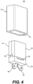
- FIG. 8 is a first perspective view of another capsule for an aerosol-generating device according to an example embodiment.
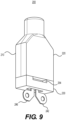
- FIG. 9 is a second perspective view of the capsule of FIG. 8 .
- a capsule 200 includes a housing configured to hold an aerosol-forming substrate and to accommodate a heater configured to heat the aerosol-forming substrate to generate an aerosol.
- the housing of the capsule 200 includes a base portion 230, a first cover 210, and a second cover 220.
- the base portion 230 includes an engagement assembly (e.g., engagement assembly 236 in FIG. 10 ) configured to facilitate a connection with the first cover 210 and the second cover 220.
- the first cover 210 and the second cover 220 jointly define an aerosol outlet 274 therebetween.
- the capsule 200 may be regarded as one that is of a 3-piece construction.
- the base portion 230 and the first cover 210 when connected, define a first air inlet 252 therebetween.
- the base portion 230 and the second cover 220 when connected, define a second air inlet 254 therebetween.
- the first air inlet 252 and the second air inlet 254 are in fluidic communication with the aerosol outlet 274.
- the downstream sector of the capsule 200 may taper to a mouth end (e.g., cylindrical end) defining the aerosol outlet 274.
- a heater is configured to extend through the base portion 230 such that the first end section 242 and the second end section 246 are visible while the intermediate section of the heater is hidden from view when the capsule 200 is assembled. The heater will be discussed in further detail in connection with subsequent drawings.
- the aerosol outlet 274 may be defined as a plurality of outlets (e.g., 2-4 outlets).
- the aerosol outlet 274 may be defined by the first cover 210 and the second cover 220 or, alternatively, by a separate insert or end cap.
- the aerosol outlet 274, when provided as a plurality of outlets, may be arranged in a linear/sequential manner, in a radial manner, or in an array of rows and columns.
- the shape of the aerosol outlet 274 may be circular, elongated (e.g., elliptical), polygonal (e.g., rounded rectangular), or of another suitable shape.
- FIG. 10 is a partially exploded view of the capsule of FIG. 8 .
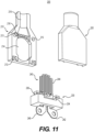
- FIG. 11 is a partially exploded view of the capsule of FIG. 9 .
- the first cover 210 and the second cover 220 are configured to engage with each other and with the base portion 230 during the assembly of the capsule 200.
- the first cover 210 includes a first protrusion 213 and defines a first orifice 215, while the second cover 220 includes a second protrusion 223 and defines a second orifice 225.
- first protrusion 213 of the first cover 210 will mate with the second orifice 225 of the second cover 220, while the second protrusion 223 of the second cover 220 will mate with the first orifice 215 of the first cover 210.
- the resulting engagement between the first cover 210 and the second cover 220 may be via an interference fit.
- the first cover 210 also defines one or more of a first notch 212, a first recess 214, a first groove 216, and a first channel 218.
- the second cover 220 defines one or more of a second notch 222, a second recess 224, a second groove 226, and a second channel 228.
- the first cover 210 and the second cover 220 may be identical parts. In such instances, orienting the first cover 210 and the second cover 220 to face each other for mating (as well as for coupling with the base portion 230) will result in a complementary arrangement. As a result, one part may be used interchangeably as the first cover 210 or the second cover 220, thus simplifying the method of manufacturing.
- the first recess 214 of the first cover 210 and the second recess 224 of the second cover 220 collectively form a chamber 264 (e.g., FIG. 12 ) configured to accommodate both an aerosol-forming substrate and an intermediate section 244 of the heater 240.
- the first interior surface of the first cover 210 further defines a first channel 218 downstream from the first recess 214
- the second interior surface of the second cover 220 further defines a second channel 228 downstream from the second recess 224.
- the first channel 218 and the second channel 228 are configured to collectively form an aerosol channel 268 (e.g., FIG. 12 ).
- first interior surface of the first cover 210 further defines first grooves 216 connecting the first recess 214 to the first channel 218, and the second interior surface of the second cover 220 further defines second grooves 226 connecting the second recess 224 to the second channel 228.
- the first grooves 216 and the second grooves 226 are aligned and dimensioned so as to collectively form passageways 266 (e.g., FIG. 12 ) configured to retain the aerosol-forming substrate within the chamber 264 while allowing the aerosol generated to pass through to the aerosol channel 268.
- the number of passageways 266 may range from four to eight (e.g., six), although example embodiments are not limited thereto.
- the first notch 212 in the first cover 210 may be defined as a pair of notches at the upstream corners of the first cover 210, wherein each notch may be adjacent to/exposed by the upstream end surface of the first cover 210 while bounded/obscured by a corresponding side surface of the first cover 210 (e.g., FIG. 11 ).
- the second notch 222 may be defined as a pair of notches at the upstream corners of the second cover 220, wherein each notch may be adjacent to/exposed by the upstream end surface of the second cover 220 while bounded/obscured by a corresponding side surface of the second cover 220 (e.g., FIG. 10 ).
- first notch 212 and the second notch 222 may be provided as discussed in connection with the first notch 112 (e.g., FIG. 6 ) and the second notch 122 (e.g., FIG. 5 ), respectively, so as to also be exposed by a corresponding side surface of the first cover 210 and the second cover 220, respectively.
- first notch 212 and the second notch 222 collectively form a T-shaped notch configured to mate with the engagement assembly 236 when the first cover 210 and the second cover 220 are coupled with the base portion 230.
- the engagement assembly 236 may be an integrally formed part of the base portion 230.
- the engagement assembly 236 of the base portion 230 includes a pair of mating members.
- the pair of mating members of the engagement assembly 236 may be adjacent to and slightly spaced away from the corresponding opposite edges of the base portion 230.
- the engagement assembly 236 may be hidden/obscured from view by the first cover 210 and the second cover 220 when the capsule 200 is assembled.
- the pair of mating members of the engagement assembly 236 may be positioned against (e.g., flush with) the corresponding opposite edges of the base portion 230, such as that disclosed in connection with the engagement assembly 136 of capsule 100 (e.g., FIG. 5 ).
- Each of the pair of mating members of the engagement assembly 236 may have a head section and a body section, wherein the head section is wider than the body section.
- each of the pair of mating members of the engagement assembly 236 may have a T shape corresponding to the T-shaped notch collectively formed by the first notch 212 of the first cover 210 and the second notch 222 of the second cover 220.
- the base portion 230 defines a first indentation 232 and a second indentation 234.
- the surface of the base portion 230 defining the first indentation 232 and a corresponding surface of the first cover 210 jointly define the first air inlet 252 (e.g., FIG. 8 ).
- the surface of the base portion 230 defining the second indentation 234 and a corresponding surface of the second cover 220 jointly define the second air inlet 254 (e.g., FIG. 9 ).
- the first air inlet 252 and the second air inlet 254 are in fluidic communication with the chamber (e.g., chamber 264 in FIG.
- the aerosol-forming substrate (not illustrated) for the capsule 200 may be as described in connection with any of the forms/formats for the first aerosol-forming substrate 160a and/or the second aerosol-forming substrate 160b of the capsule 100 (e.g., FIG. 5 ).
- the relevant disclosures above with regard to aerosol-forming substrates should be understood to apply to this section and may not have been repeated in the interest of brevity.
- a sheet material may be cut or otherwise processed (e.g., stamping, electrochemical etching, die cutting, laser cutting) to produce the heater 240.
- the sheet material may be formed of one or more conductors configured to undergo Joule heating (which is also known as ohmic/resistive heating).
- Suitable conductors for the sheet material include an iron-based alloy (e.g., stainless steel, iron aluminides), a nickel-based alloy (e.g., nichrome), and/or a ceramic (e.g., ceramic coated with metal).
- the stainless steel may be a type known in the art as SS316L, although example embodiments are not limited thereto.
- the sheet material may have a thickness of about 0.1 - 0.3 mm (e.g., 0.15 - 0.25 mm).
- the heater 240 has a first end section 242, an intermediate section 244, and a second end section 246.
- the first end section 242 and the second end section 246 are configured to receive an electric current from a power source during an activation of the heater 240.
- the heater 240 is activated (e.g., so as to undergo Joule heating)
- the temperature of the aerosol-forming substrate may increase, and an aerosol may be generated and drawn or otherwise released through the aerosol outlet 274 of the capsule 200.
- the first end section 242 and the second end section 246 may each define an aperture to facilitate an electrical connection with the power source, although example embodiments are not limited thereto.
- the heater 240 may be produced from a sheet material, the first end section 242, the second end section 246, and the intermediate section 244 may be coplanar. Furthermore, the intermediate section 244 of the heater 240 may have a planar and winding form resembling a compressed oscillation or zigzag with a plurality of parallel segments (e.g., eight to twelve parallel segments). However, it should be understood that other forms for the intermediate section 244 of the heater 240 are also possible (e.g., spiral form, flower-like form).
- the heater 240 extends through the base portion 230.
- the first end section 242 and the second end section 246 may be regarded as external segments of the heater 240 disposed on an opposite side of the base portion 230 from the engagement assembly 236.
- the intermediate section 244 of the heater 240 may be on the downstream side of the base portion 230, while the terminus of each of the first end section 242 and the second end section 246 may be on the upstream side of the base portion 230.
- the heater 240 may be seated within a slot extending through the base portion 230.
- the heater 240 may be provided with a base insert which covers segments of the heater 240 between the intermediate section 244 and the terminus of each of the first end section 242 and the second end section 246.
- the base insert will be between the heater 240 and the base portion 230 so as to create a relatively close-fit arrangement, thus allowing the base portion 230 to grip the heater 240 in a relatively secure manner.
- the heater 240 may be embedded within the base portion 230 via injection molding (e.g., insert molding, over molding). For instance, the heater 240 may be embedded such that the intermediate section 244 is between the pair of mating members of the engagement assembly 236.
- first end section 242 and the second end section 246 of the heater 240 are shown in the drawings as projections extending from the upstream side of the base portion 230, it should be understood that, in some example embodiments, the first end section 242 and the second end section 246 of the heater 240 may be configured so as to constitute parts of the upstream end face of the capsule 200.
- the exposed portions of the first end section 242 and the second end section 246 of the heater 240 may be dimensioned and oriented so as to be situated/folded against (e.g., substantially coplanar with) the underside or bottom of the base portion 230.
- the first end section 242 and the second end section 246 may constitute a first electrical contact pad and a second electrical contact pad, respectively, as well as parts of the upstream end face of the capsule 200.
- the first cover 210 and the second cover 220 are configured to engage with each other and with the base portion 230 such that their adjacent surfaces are substantially flush.
- the main external surface of the first cover 210 may be flush with the front surface of the base portion 230 (e.g., FIG. 8 ).
- the main external surface of the second cover 220 may be flush with the rear surface of the base portion 230 (e.g., FIG. 9 ).
- the opposing side surfaces of the base portion 230 may be flush with the adjoining side surfaces of the first cover 210 and the second cover 220.
- the downstream end surface of the first cover 210 may be flush with the downstream end surface of the second cover 220.
- the resulting structure (e.g., housing) of the capsule 200 may have an upstream sector with a form resembling a cuboid with a front face, an opposing rear face, a first side face, an opposing second side face, and an upstream end face.
- the upstream sector of the capsule 200 may have a rectangular cross-section.
- the cuboid form of the upstream sector of the capsule 200 may have a square cross-section.
- example embodiments are not limited thereto.
- the upstream sector of the capsule 200 may have a form resembling a cylinder (e.g., elliptic cylinder, circular cylinder).
- a cylinder e.g., elliptic cylinder, circular cylinder.
- the upstream sector of the capsule 200 may have an elliptical cross-section.
- the upstream sector of the capsule 200 may have a circular cross-section.
- the main external surface of the first cover 210 and the front surface of the base portion 230 may be jointly regarded as the front face (e.g., which defines the first air inlet 252).
- the main external surface of the second cover 220 and the rear surface of the base portion 230 may be jointly regarded as the opposing rear face (e.g., which defines the second air inlet 254).
- the opposing side surfaces of the base portion 230 and the corresponding side surfaces of the first cover 210 and the second cover 220 may be jointly regarded as the first side face and the opposing second side face of the housing.
- the underside or bottom of the base portion 230 may be regarded as the upstream end face (e.g., from which the first end section 242 and the second end section 246 of the heater extend).
- the downstream end surface of the first cover 210 and the corresponding downstream end surface of the second cover 220 may be jointly regarded as the downstream end face.
- downstream sector of the capsule 200 may taper to a cylindrical end defining the aerosol outlet 274.
- the downstream sector of the capsule 200 may taper to a polygonal end, which may be a cuboidal end with a rectangular or square cross-section.
- the downstream sector of the capsule 200 may taper to a flattened end resembling a wedge, chisel, duckbill shape.
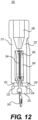
- FIG. 12 is a cross-sectional view of the capsule of FIG. 8 .
- the upstream portions/ends of the first cover 210 and the second cover 220 are coupled/engaged with the base portion 230, while the downstream portions/ends of the first cover 210 and the second cover 220 form a mouth end defining an aerosol channel 268 and an aerosol outlet 274 (e.g., FIG. 8 ).
- the aerosol channel 268 is downstream from and in fluidic communication with the chamber 264 via the passageways 266.
- the first air inlet 252, the second air inlet 254, the chamber 264, the passageways 266, and the aerosol channel 268 are all in fluidic communication with each other so as to permit a flow of air/aerosol therethrough.
- the air may enter the capsule 200 through the first air inlet 252 and the second air inlet 254 (e.g., through the front face and the rear face of the capsule 200). After being drawn into the capsule 200, the air may flow longitudinally along the intermediate section 244 of the heater 240 and through the aerosol-forming substrate (not illustrated) within the chamber 264. Inside the chamber 264, volatiles are released by the aerosol-forming substrate heated by the intermediate section 244 of the heater 240 to produce an aerosol which is entrained by the air flowing through the chamber 264, the passageways 266, and the aerosol channel 268 before exiting the capsule 200 through the aerosol outlet 274.
- FIG. 13 is a first perspective view of another capsule for an aerosol-generating device according to an example embodiment.
- FIG. 14 is a second perspective view of the capsule of FIG. 13 .
- the capsule 300 in FIGS. 13-14 may resemble the capsule 200 in FIGS. 8-9 while differing with regard to the internal slots defined by the first cover 310 and the second cover 320 as well as the corresponding external protuberances, which will be discussed in more detail herein.
- the relevant disclosures above of the features in common should be understood to apply to this section and may not have been repeated in the interest of brevity.
- the capsule 300 includes a housing configured to hold an aerosol-forming substrate as described herein and to accommodate a heater configured to heat the aerosol-forming substrate to generate an aerosol.
- the housing of the capsule 300 includes a base portion 330, a first cover 310, and a second cover 320.
- the base portion 330 includes an engagement assembly (e.g., engagement assembly 336 in FIG. 15 ) configured to facilitate a connection with the first cover 310 and the second cover 320.
- the first cover 310 and the second cover 320 jointly define an aerosol outlet 374 therebetween.
- the capsule 300 may be regarded as one that is of a 3-piece construction.
- the base portion 330 and the first cover 310 when connected, define a first air inlet 352 therebetween.
- the base portion 330 and the second cover 320 when connected, define a second air inlet 354 therebetween.
- the first air inlet 352 and the second air inlet 354 are in fluidic communication with the aerosol outlet 374.
- air drawn into the first air inlet 352 and the second air inlet 354 will flow through the capsule 300 to the aerosol outlet 374.
- the downstream sector of the capsule 300 may taper to a mouth end (e.g., cylindrical end) defining the aerosol outlet 374.
- a heater is configured to extend through the base portion 330 such that the first end section 342 and the second end section 346 are visible while the intermediate section 344 of the heater 340 (e.g., FIG. 15 ) is hidden from view when the capsule 300 is assembled.
- the aerosol outlet 374, the first air inlet 352, the second air inlet 354, the base portion 330, the first end section 342, and the second end section 346 in FIGS. 13-14 may be the same as described in connection with the aerosol outlet 274, the first air inlet 252, the second air inlet 254, the base portion 230, the first end section 242, and the second end section 246 in FIGS. 8-9 .
- the relevant disclosures above of the features in common should be understood to apply to this section and may not have been repeated in the interest of brevity.
- FIG. 15 is a partially exploded view of the capsule of FIG. 13 .
- FIG. 16 is a partially exploded view of the capsule of FIG. 14 .
- the first interior surface of the first cover 310 defines a first slot 317 oriented orthogonally to the first channel 318, while the second interior surface of the second cover 320 defines a second slot 327 oriented orthogonally to the second channel 328.
- Each of the first slot 317 and the second slot 327 may be a half-disk-shaped concavity, although example embodiments are not limited thereto.
- the first cover 310 may have a first external protuberance corresponding to the first slot 317.
- the second cover 320 may have a second external protuberance corresponding to the second slot 327.
- the thicknesses of the first cover 310 and the second cover 320 may be increased such that the depths of the first slot 317 and the second slot 327 do not result in corresponding external protuberances in the first cover 310 and the second cover 320.
- the first slot 317 and the second slot 327 collectively form a compartment (e.g., compartment 367 in FIG. 17 ).
- the compartment is configured to accommodate at least one of a filter or a flavor medium as described herein.
- the compartment may be a disk-shaped concavity. However, it should be understood that other shaped compartments (and, thus, other shaped slots) may be provided.
- the compartment may be a polygon-shaped (e.g., square-shaped, hexagon-shaped, octagon-shaped) concavity configured to accommodate a similarly shaped filter and/or flavor medium.
- first cover 310 and the second cover 320 in FIGS. 15-16 may be the same as described in connection with the first cover 210 and the second cover 220 in FIGS. 10-11 .
- first notch 312, the first protrusion 313, the first recess 314, the first orifice 315, the first groove 316, and the first channel 318 in FIG. 16 may be the same as described in connection with the first notch 212, the first protrusion 213, the first recess 214, the first orifice 215, the first groove 216, and the first channel 218 in FIG. 11 .
- the second notch 322, the second protrusion 323, the second recess 324, the second orifice 325, the second groove 326, and the second channel 328 in FIG. 15 may be the same as described in connection with the second notch 222, the second protrusion 223, the second recess 224, the second orifice 225, the second groove 226, and the second channel 228 in FIG. 10 .
- first cover 310 and the second cover 320 may be identical parts. In such instances, orienting the first cover 310 and the second cover 320 to face each other for mating (as well as for coupling with the base portion 330) will result in a complementary arrangement. As a result, one part may be used interchangeably as the first cover 310 or the second cover 320, thus simplifying the method of manufacturing.
- the base portion 330 and the heater 340 in FIGS. 15-16 may be the same as described in connection with the base portion 230 and the heater 240 in FIGS. 10-11 .
- the first indentation 332, the second indentation 334, and the engagement assembly 336 of the base portion 330 in FIGS. 15-16 may be the same as described in connection with the first indentation 232, the second indentation 234, and the engagement assembly 236 of the base portion 230 in FIGS. 10-11 .
- 15-16 may be the same as described in connection with the first end section 242, the intermediate section 244, and the second end section 246 of the heater 240 in FIGS. 10-11 .
- the relevant disclosures above of the features in common should be understood to apply to this section and may not have been repeated in the interest of brevity.
- FIG. 17 is a cross-sectional view of the capsule of FIG. 13 .
- the upstream portions/ends of the first cover 310 and the second cover 320 are coupled/engaged with the base portion 330, while the downstream portions/ends of the first cover 310 and the second cover 320 form a mouth end defining an aerosol channel 368 and an aerosol outlet 374 (e.g., FIG. 13 ).
- the aerosol channel 368 is downstream from and in fluidic communication with the compartment 367.
- the compartment 367 is in fluidic communication with the chamber 364 via the passageways 366.
- first air inlet 352, the second air inlet 354, the chamber 364, the passageways 366, the compartment 367, and the aerosol channel 368 are all in fluidic communication with each other so as to permit a flow of air/aerosol therethrough.
- the air may enter the capsule 300 through the first air inlet 352 and the second air inlet 354 (e.g., through the front face and the rear face of the capsule 300). After being drawn into the capsule 300, the air may flow longitudinally along the intermediate section 344 of the heater 340 and through the aerosol-forming substrate (not illustrated) within the chamber 364.
- the aerosol-forming substrate for the capsule 300 may be as described in connection with any of the forms/formats for the first aerosol-forming substrate 160a and/or the second aerosol-forming substrate 160b of the capsule 100 (e.g., FIG. 5 ).
- the relevant disclosures above with regard to aerosol-forming substrates should be understood to apply to this section and may not have been repeated in the interest of brevity.
- the aerosol-forming substrate heated by the intermediate section 344 of the heater 340 to produce an aerosol which is entrained by the air flowing through the chamber 364, the passageways 366, the compartment 367, and the aerosol channel 368 before exiting the capsule 300 through the aerosol outlet 374.
- at least one of a filter or a flavor medium as described herein may be provided within the compartment 367 such that the aerosol generated in the chamber 364 passes through at least one of the filter or the flavor medium before flowing through the aerosol channel 368.
- FIG. 18 is a front view of an aerosol-generating device according to an example embodiment.
- an aerosol-generating device 1000 e.g., heat-not-burn aerosol-generating device
- the capsule 400 may be the same as described in connection with the capsule 100, the capsule 200, and/or the capsule 300 so as to cover various combinations of the disclosed features.
- the capsule 400 may include a housing containing an aerosol-forming substrate and a heater that undergoes resistive heating when activated.
- the housing may include a base portion, a first cover, and a second cover.
- the first cover and the second cover may jointly define therebetween a chamber, an aerosol channel, and an aerosol outlet, wherein the aerosol-forming substrate is disposed in the chamber.
- the heater is supported by the base portion and extends into the chamber.
- the device body 1025 may define a socket or concavity configured to receive the capsule 400 such that the device body 1025 is mechanically and electrically engaged with the capsule 400.
- the socket or concavity of the device body 1025 may be configured to grip at least two opposite external surfaces (e.g., opposing sidewalls) of the capsule 400.
- the device body 1025 and/or the capsule 400 may include a magnet configured to establish a magnetic arrangement such the device body 1025 will attract and retain the capsule 400.
- the device body 1025 may include a first electrode and a second electrode within the socket or concavity that are configured to electrically contact a first end section and a second end section, respectively, of a heater of the capsule 400.
- a power source 1035 and control circuitry 1045 may be disposed within the device body 1025 of the aerosol-generating device 1000.
- the power source 1035 may include one or more batteries (e.g., rechargeable battery).
- the control circuitry 1045 may instruct the power source 1035 to supply an electric current to the capsule 400 via the first electrode and the second electrode of the device body 1025.
- the supply of current from the power source 1035 may be in response to a manual operation (e.g., button-activation) or an automatic operation (e.g., puff-activation).
- the aerosol-forming substrate within the capsule 400 may be heated to generate an aerosol.
- the change in resistance of the heater may be used by the control circuitry 1045 to monitor and control the aerosolization temperature.
- the aerosol generated may be drawn from the aerosol-generating device 1000 via the aerosol outlet at the mouth end of the capsule 400.
- a method of generating an aerosol may include supplying an electric current to the capsule 400 so as to heat (e.g., via resistive heating) an aerosol-forming substrate therein.
- the method may additionally include drawing the aerosol generated within the chamber of the capsule 400 such that the aerosol flows through the aerosol channel and exits the aerosol outlet of the capsule 400.
Landscapes
- Health & Medical Sciences (AREA)
- Natural Medicines & Medicinal Plants (AREA)
- Life Sciences & Earth Sciences (AREA)
- Engineering & Computer Science (AREA)
- Animal Behavior & Ethology (AREA)
- General Health & Medical Sciences (AREA)
- Public Health (AREA)
- Veterinary Medicine (AREA)
- Anesthesiology (AREA)
- Biomedical Technology (AREA)
- Heart & Thoracic Surgery (AREA)
- Hematology (AREA)
- Biotechnology (AREA)
- Mycology (AREA)
- Chemical & Material Sciences (AREA)
- Botany (AREA)
- Medical Informatics (AREA)
- Medicinal Chemistry (AREA)
- Microbiology (AREA)
- Alternative & Traditional Medicine (AREA)
- Pharmacology & Pharmacy (AREA)
- Epidemiology (AREA)
- Bioinformatics & Cheminformatics (AREA)
- Pulmonology (AREA)
- Containers And Packaging Bodies Having A Special Means To Remove Contents (AREA)
- Thermotherapy And Cooling Therapy Devices (AREA)
- Oscillators With Electromechanical Resonators (AREA)
- Resistance Heating (AREA)
Priority Applications (1)
| Application Number | Priority Date | Filing Date | Title |
|---|---|---|---|
| EP24223771.7A EP4563020A1 (en) | 2021-01-04 | 2021-11-23 | Capsules with integrated mouthpieces, heat-not-burn (hnb) aerosol-generating devices, and methods of generating an aerosol |
Applications Claiming Priority (2)
| Application Number | Priority Date | Filing Date | Title |
|---|---|---|---|
| US17/140,215 US12053022B2 (en) | 2021-01-04 | 2021-01-04 | Capsules with integrated mouthpieces, heat-not-burn (HNB) aerosol-generating devices, and methods of generating an aerosol |
| PCT/US2021/060505 WO2022146581A1 (en) | 2021-01-04 | 2021-11-23 | Capsules with integrated mouthpieces, heat-not-burn (hnb) aerosol-generating devices, and methods of generating an aerosol |
Related Child Applications (1)
| Application Number | Title | Priority Date | Filing Date |
|---|---|---|---|
| EP24223771.7A Division EP4563020A1 (en) | 2021-01-04 | 2021-11-23 | Capsules with integrated mouthpieces, heat-not-burn (hnb) aerosol-generating devices, and methods of generating an aerosol |
Publications (2)
| Publication Number | Publication Date |
|---|---|
| EP4271214A1 EP4271214A1 (en) | 2023-11-08 |
| EP4271214B1 true EP4271214B1 (en) | 2025-01-01 |
Family
ID=78918683
Family Applications (2)
| Application Number | Title | Priority Date | Filing Date |
|---|---|---|---|
| EP21827502.2A Active EP4271214B1 (en) | 2021-01-04 | 2021-11-23 | Capsules with integrated mouthpieces, heat-not-burn (hnb) aerosol-generating devices, and methods of generating an aerosol |
| EP24223771.7A Pending EP4563020A1 (en) | 2021-01-04 | 2021-11-23 | Capsules with integrated mouthpieces, heat-not-burn (hnb) aerosol-generating devices, and methods of generating an aerosol |
Family Applications After (1)
| Application Number | Title | Priority Date | Filing Date |
|---|---|---|---|
| EP24223771.7A Pending EP4563020A1 (en) | 2021-01-04 | 2021-11-23 | Capsules with integrated mouthpieces, heat-not-burn (hnb) aerosol-generating devices, and methods of generating an aerosol |
Country Status (7)
| Country | Link |
|---|---|
| US (2) | US12053022B2 (enExample) |
| EP (2) | EP4271214B1 (enExample) |
| JP (1) | JP7704870B2 (enExample) |
| KR (1) | KR102941126B1 (enExample) |
| CN (1) | CN117042639A (enExample) |
| CA (1) | CA3203089A1 (enExample) |
| WO (1) | WO2022146581A1 (enExample) |
Families Citing this family (12)
| Publication number | Priority date | Publication date | Assignee | Title |
|---|---|---|---|---|
| US12011034B2 (en) * | 2021-01-18 | 2024-06-18 | Altria Client Services Llc | Capsules including embedded heaters and heat-not-burn (HNB) aerosol-generating devices |
| EP4573847A1 (en) * | 2022-09-19 | 2025-06-25 | Altria Client Services LLC | Electrical contact pads with surface discontinuities and power-receiving units and electronic devices including the same |
| US20240148060A1 (en) * | 2022-09-19 | 2024-05-09 | Altria Client Services Llc | Heat-not-burn (hnb) aerosol-generating devices and capsules having electrical contact pads with surface discontinuities |
| WO2024064669A1 (en) * | 2022-09-19 | 2024-03-28 | Altria Client Services Llc | Capsules having electrical contact pads with surface discontinuities and heat-not-burn (hnb) aerosol-generating devices including the same |
| USD1051071S1 (en) | 2022-11-07 | 2024-11-12 | Altria Client Services Llc | Set of electrical contact pads |
| KR20260050357A (ko) * | 2023-08-10 | 2026-04-14 | 필립모리스 프로덕츠 에스.에이. | 에어로졸 발생 장치에 사용하기 위한 카트리지 |
| CN121908958A (zh) * | 2023-08-10 | 2026-04-21 | 菲利普莫里斯生产公司 | 用于在气溶胶生成装置中使用的筒 |
| WO2025133320A1 (en) * | 2023-12-21 | 2025-06-26 | Philip Morris Products S.A. | Aerosol-generating article comprising a frame |
| WO2025132264A1 (en) * | 2023-12-21 | 2025-06-26 | Philip Morris Products S.A. | Aerosol-generating article with concave internal wall |
| WO2025132425A1 (en) * | 2023-12-21 | 2025-06-26 | Philip Morris Products S.A. | Aerosol-generating article |
| WO2025141022A1 (en) * | 2023-12-28 | 2025-07-03 | Philip Morris Products S.A. | Symmetric cartridge for aerosol-generating device |
| WO2025162878A1 (en) * | 2024-02-01 | 2025-08-07 | Philip Morris Products S.A. | Cartridge with porous matrix for storing liquid aerosol-forming substrate |
Citations (2)
| Publication number | Priority date | Publication date | Assignee | Title |
|---|---|---|---|---|
| WO2016005530A1 (en) * | 2014-07-11 | 2016-01-14 | Philip Morris Products S.A. | Aerosol-forming cartridge comprising a liquid nicotine source |
| EP3462931B1 (en) * | 2016-05-31 | 2021-06-23 | Philip Morris Products S.A. | Fluid permeable heater assembly for aerosol-generating systems and flat electrically conductive filament arrangement for fluid permeable heater assemblies |
Family Cites Families (110)
| Publication number | Priority date | Publication date | Assignee | Title |
|---|---|---|---|---|
| US1934887A (en) | 1933-11-14 | Electric vaporizer | ||
| US855984A (en) | 1905-09-02 | 1907-06-04 | Fred J Russell | Medicine-receptacle. |
| US1071389A (en) | 1912-07-08 | 1913-08-26 | Joseph W Blosser | Vaporizer and inhaler. |
| DE2730855B2 (de) | 1977-07-08 | 1979-12-13 | Globol-Werk Gmbh, 8858 Neuburg | Vorrichtung zum Verdampfen von in Zellstoffplatten oder anderen festen Trägermaterialien eingelagerten Wirkstoffen |
| US4564748A (en) | 1982-10-29 | 1986-01-14 | Respiratory Care, Inc. | Variable temperature heating control system for inhalation therapy apparatus |
| US4947874A (en) | 1988-09-08 | 1990-08-14 | R. J. Reynolds Tobacco Company | Smoking articles utilizing electrical energy |
| GB8909891D0 (en) | 1989-04-28 | 1989-06-14 | Riker Laboratories Inc | Device |
| US5665262A (en) | 1991-03-11 | 1997-09-09 | Philip Morris Incorporated | Tubular heater for use in an electrical smoking article |
| CA2069687A1 (en) | 1991-06-28 | 1992-12-29 | Chandra Kumar Banerjee | Tobacco smoking article with electrochemical heat source |
| US5337740A (en) | 1991-08-01 | 1994-08-16 | New England Pharmaceuticals, Inc. | Inhalation devices |
| DE4142238A1 (de) | 1991-12-20 | 1993-06-24 | Boehringer Ingelheim Kg | Pulverinhalator mit pulvertraeger aus regelmaessigen mikrostrukturen |
| US5441060A (en) | 1993-02-08 | 1995-08-15 | Duke University | Dry powder delivery system |
| FI954098A7 (fi) | 1993-03-03 | 1995-09-01 | Tenax Corp | Kuivajauheen inhalaattorin lääkeaineen kantolaite |
| US5388572A (en) | 1993-10-26 | 1995-02-14 | Tenax Corporation (A Connecticut Corp.) | Dry powder medicament inhalator having an inhalation-activated piston to aerosolize dose and deliver same |
| US5388573A (en) | 1993-12-02 | 1995-02-14 | Tenax Corporation | Dry powder inhalator medicament carrier |
| US5647347A (en) | 1994-10-21 | 1997-07-15 | Glaxo Wellcome Inc. | Medicament carrier for dry powder inhalator |
| EP0938907B1 (en) | 1996-01-03 | 2001-12-05 | Glaxo Group Limited | Inhalation device |
| US6006747A (en) | 1997-03-20 | 1999-12-28 | Dura Pharmaceuticals, Inc. | Dry powder inhaler |
| US6250301B1 (en) | 1997-08-28 | 2001-06-26 | Hortal Harm B.V. | Vaporizer for inhalation and method for extraction of active ingredients from a crude natural product or other matrix |
| US6095153A (en) | 1998-06-19 | 2000-08-01 | Kessler; Stephen B. | Vaporization of volatile materials |
| ES2187402T3 (es) | 1999-02-17 | 2003-06-16 | Johnson & Son Inc S C | Dispositivo para dispensar materiales volatiles. |
| GB2377218A (en) | 2001-05-04 | 2003-01-08 | Gw Pharmaceuticals Ltd | Process and apparatus for extraction of active substances and enriched extracts from natural products |
| GB0126150D0 (en) | 2001-10-31 | 2002-01-02 | Gw Pharma Ltd | A device method and resistive element for vaporising a substance |
| GB2381450B (en) | 2001-10-31 | 2006-05-31 | Gw Pharma Ltd | Compositions for administration of natural or synthetic cannabinoids by vaporisation |
| ES2203320B1 (es) | 2002-04-12 | 2005-07-01 | DBK ESPAñA, S.A. | Dispositivo evaporador de sustancias activas. |
| US7878193B2 (en) | 2003-01-14 | 2011-02-01 | Boehringer Ingelheim International Gmbh | Capsule for taking an active substance which can be inhaled |
| US7997280B2 (en) | 2004-01-30 | 2011-08-16 | Joshua Rosenthal | Portable vaporizer |
| US7186958B1 (en) | 2005-09-01 | 2007-03-06 | Zhao Wei, Llc | Inhaler |
| US20070102013A1 (en) | 2005-09-30 | 2007-05-10 | Philip Morris Usa Inc. | Electrical smoking system |
| JP2008035742A (ja) | 2006-08-03 | 2008-02-21 | British American Tobacco Pacific Corporation | 揮発装置 |
| US7518123B2 (en) | 2006-09-25 | 2009-04-14 | Philip Morris Usa Inc. | Heat capacitor for capillary aerosol generator |
| US20100139655A1 (en) | 2006-11-19 | 2010-06-10 | Aespironics Ltd | Dry-powder inhaler |
| IL191190A0 (en) | 2008-05-01 | 2009-08-03 | Dan Adler | Dry powder inhaler |
| US20090293892A1 (en) | 2008-05-30 | 2009-12-03 | Vapor For Life | Portable vaporizer for plant material |
| US20090293888A1 (en) | 2008-05-30 | 2009-12-03 | Vapor For Life | Portable vaporizer for plant material |
| EP2145643A1 (de) | 2008-07-19 | 2010-01-20 | Markus Storz | Portioniertes Arzneimittel |
| WO2010036839A2 (en) | 2008-09-26 | 2010-04-01 | Oriel Therapeutics, Inc. | Inhalers with airway disks having discrete airway channels and related disks and methods |
| AU2010226152B2 (en) | 2009-03-17 | 2014-09-25 | Philip Morris Products Sa | Tobacco-based nicotine aerosol generation system |
| EP2253233A1 (en) | 2009-05-21 | 2010-11-24 | Philip Morris Products S.A. | An electrically heated smoking system |
| US8488952B2 (en) | 2009-06-22 | 2013-07-16 | Magic-Flight General Manufacturing, Inc. | Aromatic vaporizer |
| US8490627B2 (en) | 2009-09-29 | 2013-07-23 | Steven Elliot Levin | Vaporizer with foil heat exchanger |
| EP2327318A1 (en) | 2009-11-27 | 2011-06-01 | Philip Morris Products S.A. | An electrically heated smoking system with internal or external heater |
| US20130186392A1 (en) | 2010-01-20 | 2013-07-25 | Koninklijke Philips Electronics, N.V. | Aerosol delivery system with temperature-based aerosol detector |
| US20110192399A1 (en) | 2010-02-11 | 2011-08-11 | Lance Alexander Wilke | Vaporizer with improved heating chamber and related methods |
| RU2013103502A (ru) | 2010-06-28 | 2014-08-10 | Паллиатек | Система подачи и контроля лекарственных средств на основе каннабиса |
| US8910630B2 (en) | 2010-06-28 | 2014-12-16 | Palliatech, Inc. | Cannabis drug delivery and monitoring system |
| LT2982255T (lt) | 2010-08-24 | 2019-08-12 | Jt International Sa | Inhaliacinis įtaisas su medžiagos naudojimo reguliavimu |
| EP3834869B1 (en) | 2010-12-22 | 2024-06-05 | Syqe Medical Ltd. | System for drug delivery |
| EP2518499B1 (en) | 2011-03-09 | 2015-06-10 | Sensa Bues AB | A portable sampling device and method for drug detection from exhaled breath |
| WO2012156725A1 (en) | 2011-05-16 | 2012-11-22 | The Technology Partnership Plc | Dose container |
| US20120325227A1 (en) | 2011-06-24 | 2012-12-27 | Alexander Robinson | Portable vaporizer |
| TWI546023B (zh) | 2011-10-27 | 2016-08-21 | 菲利浦莫里斯製品股份有限公司 | 具有氣溶膠生產控制之電操作氣溶膠產生系統 |
| HUE040751T2 (hu) | 2011-10-27 | 2019-03-28 | Philip Morris Products Sa | Aeroszol-fejlesztõ rendszer továbbfejlesztett aeroszol-elõállítással |
| ES2589260T5 (es) | 2011-11-21 | 2022-07-15 | Philip Morris Products Sa | Extractor para un dispositivo generador de aerosol |
| EP2609820A1 (en) | 2011-12-30 | 2013-07-03 | Philip Morris Products S.A. | Detection of aerosol-forming substrate in an aerosol generating device |
| US20130233312A1 (en) | 2012-03-09 | 2013-09-12 | Harris Cohn | Portable Sublimation Device |
| KR101319228B1 (ko) | 2012-03-19 | 2013-10-16 | 권순홍 | 조절마개가 구성된 전자담배용 카트리지 |
| US20130255702A1 (en) | 2012-03-28 | 2013-10-03 | R.J. Reynolds Tobacco Company | Smoking article incorporating a conductive substrate |
| DE102012103482A1 (de) | 2012-04-20 | 2013-10-24 | Alfred Von Schuckmann | Vorrichtung zum Inhalieren pulverförmiger Substanzen |
| US20140041655A1 (en) | 2012-08-11 | 2014-02-13 | Grenco Science, Inc | Portable Vaporizer |
| JP3180859U (ja) * | 2012-08-31 | 2013-01-17 | 蕭 銘任 | 芳香カプセルを有する加熱器及び該芳香カプセル |
| US8881737B2 (en) | 2012-09-04 | 2014-11-11 | R.J. Reynolds Tobacco Company | Electronic smoking article comprising one or more microheaters |
| US11213073B2 (en) | 2012-12-27 | 2022-01-04 | George R. Breiwa, III | Tubular volatizing device |
| US9993023B2 (en) | 2013-02-22 | 2018-06-12 | Altria Client Services Llc | Electronic smoking article |
| SG11201507630SA (en) | 2013-03-15 | 2015-10-29 | Philip Morris Products Sa | Aerosol-generating device comprising multiple solid-liquid phase-change materials |
| GB201320231D0 (en) | 2013-11-15 | 2014-01-01 | British American Tobacco Co | Aerosol generating material and devices including the same |
| US20160366947A1 (en) | 2013-12-23 | 2016-12-22 | James Monsees | Vaporizer apparatus |
| JP6131340B2 (ja) | 2014-01-29 | 2017-05-17 | 日本たばこ産業株式会社 | 非燃焼型香味吸引器 |
| WO2015116934A1 (en) | 2014-01-31 | 2015-08-06 | Bourque Michale Patrick | Methods and apparatus for producing herbal vapor |
| KR102377636B1 (ko) | 2014-02-10 | 2022-03-24 | 필립모리스 프로덕츠 에스.에이. | 에어로졸 발생 시스템용 유체 투과성 히터 조립체 및 에어로졸 발생 시스템용 유체 투과성 히터를 조립하기 위한 방법 |
| KR20240032162A (ko) | 2014-02-10 | 2024-03-08 | 필립모리스 프로덕츠 에스.에이. | 히터 조립체를 구비한 에어로졸 발생 시스템용 및 유체 투과성 히터를 구비한 에어로졸 발생 시스템용 카트리지 |
| DE202014001718U1 (de) | 2014-02-27 | 2015-05-28 | Xeo Holding GmbH | Rauchvorrichtung |
| GB2527597B (en) | 2014-06-27 | 2016-11-23 | Relco Induction Dev Ltd | Electronic Vapour Inhalers |
| GB201500582D0 (en) | 2015-01-14 | 2015-02-25 | British American Tobacco Co | Apparatus for heating or cooling a material contained therein |
| RU2721064C2 (ru) | 2014-06-30 | 2020-05-15 | Сике Медикал Лтд. | Ингалятор с регулированием потока |
| PL3160554T3 (pl) | 2014-06-30 | 2022-02-21 | Syqe Medical Ltd. | Urządzenia i systemy do dopłucnego dostarczania środków aktywnych |
| IL273507B2 (en) | 2014-06-30 | 2024-06-01 | Syqe Medical Ltd | Methods, devices and systems for administering active substances through the lungs |
| RU2723335C2 (ru) | 2014-06-30 | 2020-06-09 | Сике Медикал Лтд. | Дозовый картридж для ингалятора |
| AU2015283589B2 (en) | 2014-06-30 | 2019-09-12 | Syqe Medical Ltd. | Method and device for vaporization and inhalation of isolated substances |
| CN113616883B (zh) | 2014-06-30 | 2023-06-06 | Syqe医药有限公司 | 向受试者肺部递送植物材料中的至少一药理活性剂的系统 |
| CA2951396A1 (en) | 2014-07-11 | 2016-01-14 | Philip Morris Products S.A. | Aerosol-generating system comprising a removable heater |
| SI3166426T1 (sl) | 2014-07-11 | 2018-10-30 | Philip Morris Products S.A. | Sistem, ki proizvaja aerosol in obsega zaznavanje vložka |
| CA2951103A1 (en) | 2014-07-11 | 2016-01-14 | Philip Morris Products S.A. | Aerosol-forming cartridge with protective foil |
| JP6734838B2 (ja) | 2014-07-11 | 2020-08-05 | フィリップ・モーリス・プロダクツ・ソシエテ・アノニム | たばこ含有材料を含むエアロゾル形成カートリッジ |
| CN204146324U (zh) | 2014-08-12 | 2015-02-11 | 刘水根 | 一种电子烟草蒸发器 |
| WO2016029225A1 (en) | 2014-08-22 | 2016-02-25 | Fontem Holdings 2 B.V. | Method, system and device for controlling a heating element |
| CN104223359A (zh) | 2014-08-22 | 2014-12-24 | 云南中烟工业有限责任公司 | 一种具有气凝胶隔热层的新型卷烟加热器 |
| CN203986136U (zh) | 2014-08-27 | 2014-12-10 | 湖北中烟工业有限责任公司 | 带双开关控制电路的电加热吸烟装置 |
| GB2533080B (en) | 2014-11-11 | 2017-08-02 | Jt Int Sa | Electronic vapour inhalers |
| WO2016082108A1 (zh) | 2014-11-25 | 2016-06-02 | 朱晓春 | 一种电子烟雾化器发热装置 |
| US10179215B2 (en) | 2015-03-19 | 2019-01-15 | Altria Client Services Llc | Vaporizer for vaporizing a constituent of a plant material |
| WO2016159013A1 (ja) | 2015-04-02 | 2016-10-06 | 日本たばこ産業株式会社 | 香味吸引器 |
| HK1246104A1 (zh) | 2015-04-07 | 2018-09-07 | Philip Morris Products S.A. | 气溶胶形成基质的小袋、其制造方法以及与小袋一起使用的气溶胶生成装置 |
| PL3313216T3 (pl) | 2015-06-29 | 2019-07-31 | Philip Morris Products S.A. | Wkład do układu wytwarzania aerozolu |
| US11924930B2 (en) | 2015-08-31 | 2024-03-05 | Nicoventures Trading Limited | Article for use with apparatus for heating smokable material |
| US20170055584A1 (en) | 2015-08-31 | 2017-03-02 | British American Tobacco (Investments) Limited | Article for use with apparatus for heating smokable material |
| CN108135275B (zh) | 2015-10-22 | 2022-03-11 | 菲利普莫里斯生产公司 | 气溶胶生成制品、气溶胶生成团块、气溶胶生成团块的形成方法和包括气溶胶生成团块的气溶胶生成系统 |
| BR112018012051B1 (pt) | 2015-12-15 | 2022-07-19 | Nota Nota Fze | Aparelho para mesclagem de perfumes e processo para mesclagem de perfume que usa o mesmo |
| GB201605357D0 (en) * | 2016-03-30 | 2016-05-11 | British American Tobacco Co | Apparatus for heating aerosol generating material and a cartridge for the apparatus |
| IL265355B2 (en) | 2016-09-14 | 2026-02-01 | Altria Client Services Llc | Smoking device |
| JP7019705B2 (ja) | 2017-01-31 | 2022-02-15 | フィリップ・モーリス・プロダクツ・ソシエテ・アノニム | エアロゾル発生装置およびエアロゾル発生システム |
| MX2019009868A (es) | 2017-02-28 | 2019-12-02 | Philip Morris Products Sa | Sistema generador de aerosol con electrodos y sensores. |
| WO2018166898A1 (en) | 2017-03-16 | 2018-09-20 | Philip Morris Products S.A. | Aerosol-generating device and aerosol-generating system |
| US10292436B2 (en) | 2017-07-10 | 2019-05-21 | Arc Innovations, Inc. | Electronic smoking systems, devices, and methods |
| CN110769708B (zh) * | 2017-07-14 | 2023-06-06 | 菲利普莫里斯生产公司 | 具有通风气流的气溶胶生成系统 |
| EP3758517A1 (en) | 2018-02-26 | 2021-01-06 | Nerudia Limited | A substitute smoking consumable |
| WO2019162498A1 (en) * | 2018-02-26 | 2019-08-29 | Nerudia Limited | A substitute smoking consumable |
| US11432581B2 (en) * | 2018-09-07 | 2022-09-06 | Altria Client Services Llc | Capsule containing a matrix, device with the matrix, and method of forming the matrix |
| US11154086B2 (en) | 2019-01-21 | 2021-10-26 | Altria Client Services Llc | Capsules, heat-not-burn (HNB) aerosol-generating devices, and methods of generating an aerosol |
| CN212117074U (zh) | 2019-12-31 | 2020-12-11 | 连展科技电子(昆山)有限公司 | 电子烟的加热连接器 |
-
2021
- 2021-01-04 US US17/140,215 patent/US12053022B2/en active Active
- 2021-11-23 CA CA3203089A patent/CA3203089A1/en active Pending
- 2021-11-23 JP JP2023540686A patent/JP7704870B2/ja active Active
- 2021-11-23 EP EP21827502.2A patent/EP4271214B1/en active Active
- 2021-11-23 KR KR1020237021736A patent/KR102941126B1/ko active Active
- 2021-11-23 EP EP24223771.7A patent/EP4563020A1/en active Pending
- 2021-11-23 WO PCT/US2021/060505 patent/WO2022146581A1/en not_active Ceased
- 2021-11-23 CN CN202180089072.6A patent/CN117042639A/zh active Pending
-
2024
- 2024-06-27 US US18/756,370 patent/US12564223B2/en active Active
Patent Citations (4)
| Publication number | Priority date | Publication date | Assignee | Title |
|---|---|---|---|---|
| WO2016005530A1 (en) * | 2014-07-11 | 2016-01-14 | Philip Morris Products S.A. | Aerosol-forming cartridge comprising a liquid nicotine source |
| EP3166429A1 (en) * | 2014-07-11 | 2017-05-17 | Philip Morris Products S.a.s. | Aerosol-forming cartridge comprising a liquid nicotine source |
| EP3166429B1 (en) * | 2014-07-11 | 2019-11-13 | Philip Morris Products S.a.s. | Aerosol-forming cartridge comprising a liquid nicotine source |
| EP3462931B1 (en) * | 2016-05-31 | 2021-06-23 | Philip Morris Products S.A. | Fluid permeable heater assembly for aerosol-generating systems and flat electrically conductive filament arrangement for fluid permeable heater assemblies |
Also Published As
| Publication number | Publication date |
|---|---|
| WO2022146581A1 (en) | 2022-07-07 |
| JP7704870B2 (ja) | 2025-07-08 |
| KR102941126B1 (ko) | 2026-03-18 |
| JP2024501896A (ja) | 2024-01-16 |
| EP4563020A1 (en) | 2025-06-04 |
| US12564223B2 (en) | 2026-03-03 |
| US20220211106A1 (en) | 2022-07-07 |
| CN117042639A (zh) | 2023-11-10 |
| EP4271214A1 (en) | 2023-11-08 |
| US12053022B2 (en) | 2024-08-06 |
| US20240349794A1 (en) | 2024-10-24 |
| KR20230129404A (ko) | 2023-09-08 |
| CA3203089A1 (en) | 2022-07-07 |
Similar Documents
| Publication | Publication Date | Title |
|---|---|---|
| EP4271214B1 (en) | Capsules with integrated mouthpieces, heat-not-burn (hnb) aerosol-generating devices, and methods of generating an aerosol | |
| US12458063B2 (en) | Capsules including internal heaters, heat-not-burn (HNB) aerosol-generating devices, and methods of generating an aerosol | |
| RU2608277C2 (ru) | Электронная сигарета | |
| US12610981B2 (en) | Capsules including embedded heaters and heat-not-burn (HNB) aerosol-generating devices | |
| US12527352B2 (en) | Capsules including internal filters, heat-not-burn (HNB) aerosol-generating devices, and methods of generating an aerosol | |
| US12201148B2 (en) | Closed system capsule with airflow, heat-not-burn (HNB) aerosol-generating devices, and methods of generating an aerosol | |
| US20250338894A1 (en) | Capsules including multiple internal compartments and heat-not-burn (hnb) aerosol-generating devices including the same |
Legal Events
| Date | Code | Title | Description |
|---|---|---|---|
| STAA | Information on the status of an ep patent application or granted ep patent |
Free format text: STATUS: UNKNOWN |
|
| STAA | Information on the status of an ep patent application or granted ep patent |
Free format text: STATUS: THE INTERNATIONAL PUBLICATION HAS BEEN MADE |
|
| PUAI | Public reference made under article 153(3) epc to a published international application that has entered the european phase |
Free format text: ORIGINAL CODE: 0009012 |
|
| STAA | Information on the status of an ep patent application or granted ep patent |
Free format text: STATUS: REQUEST FOR EXAMINATION WAS MADE |
|
| 17P | Request for examination filed |
Effective date: 20230613 |
|
| AK | Designated contracting states |
Kind code of ref document: A1 Designated state(s): AL AT BE BG CH CY CZ DE DK EE ES FI FR GB GR HR HU IE IS IT LI LT LU LV MC MK MT NL NO PL PT RO RS SE SI SK SM TR |
|
| DAV | Request for validation of the european patent (deleted) | ||
| DAX | Request for extension of the european patent (deleted) | ||
| GRAP | Despatch of communication of intention to grant a patent |
Free format text: ORIGINAL CODE: EPIDOSNIGR1 |
|
| STAA | Information on the status of an ep patent application or granted ep patent |
Free format text: STATUS: GRANT OF PATENT IS INTENDED |
|
| RIC1 | Information provided on ipc code assigned before grant |
Ipc: A61K 36/81 20060101ALI20240701BHEP Ipc: A61M 15/06 20060101ALI20240701BHEP Ipc: A61M 11/04 20060101ALI20240701BHEP Ipc: A24F 40/46 20200101ALI20240701BHEP Ipc: A24F 40/42 20200101AFI20240701BHEP |
|
| INTG | Intention to grant announced |
Effective date: 20240724 |
|
| GRAS | Grant fee paid |
Free format text: ORIGINAL CODE: EPIDOSNIGR3 |
|
| GRAA | (expected) grant |
Free format text: ORIGINAL CODE: 0009210 |
|
| STAA | Information on the status of an ep patent application or granted ep patent |
Free format text: STATUS: THE PATENT HAS BEEN GRANTED |
|
| AK | Designated contracting states |
Kind code of ref document: B1 Designated state(s): AL AT BE BG CH CY CZ DE DK EE ES FI FR GB GR HR HU IE IS IT LI LT LU LV MC MK MT NL NO PL PT RO RS SE SI SK SM TR |
|
| REG | Reference to a national code |
Ref country code: GB Ref legal event code: FG4D |
|
| REG | Reference to a national code |
Ref country code: DE Ref legal event code: R096 Ref document number: 602021024439 Country of ref document: DE |
|
| REG | Reference to a national code |
Ref country code: CH Ref legal event code: EP |
|
| REG | Reference to a national code |
Ref country code: IE Ref legal event code: FG4D |
|
| REG | Reference to a national code |
Ref country code: LT Ref legal event code: MG9D |
|
| REG | Reference to a national code |
Ref country code: NL Ref legal event code: MP Effective date: 20250101 |
|
| REG | Reference to a national code |
Ref country code: AT Ref legal event code: MK05 Ref document number: 1755319 Country of ref document: AT Kind code of ref document: T Effective date: 20250101 |
|
| PG25 | Lapsed in a contracting state [announced via postgrant information from national office to epo] |
Ref country code: NL Free format text: LAPSE BECAUSE OF FAILURE TO SUBMIT A TRANSLATION OF THE DESCRIPTION OR TO PAY THE FEE WITHIN THE PRESCRIBED TIME-LIMIT Effective date: 20250101 |
|
| PG25 | Lapsed in a contracting state [announced via postgrant information from national office to epo] |
Ref country code: FI Free format text: LAPSE BECAUSE OF FAILURE TO SUBMIT A TRANSLATION OF THE DESCRIPTION OR TO PAY THE FEE WITHIN THE PRESCRIBED TIME-LIMIT Effective date: 20250101 |
|
| PG25 | Lapsed in a contracting state [announced via postgrant information from national office to epo] |
Ref country code: PL Free format text: LAPSE BECAUSE OF FAILURE TO SUBMIT A TRANSLATION OF THE DESCRIPTION OR TO PAY THE FEE WITHIN THE PRESCRIBED TIME-LIMIT Effective date: 20250101 |
|
| PG25 | Lapsed in a contracting state [announced via postgrant information from national office to epo] |
Ref country code: ES Free format text: LAPSE BECAUSE OF FAILURE TO SUBMIT A TRANSLATION OF THE DESCRIPTION OR TO PAY THE FEE WITHIN THE PRESCRIBED TIME-LIMIT Effective date: 20250101 |
|
| PG25 | Lapsed in a contracting state [announced via postgrant information from national office to epo] |
Ref country code: NO Free format text: LAPSE BECAUSE OF FAILURE TO SUBMIT A TRANSLATION OF THE DESCRIPTION OR TO PAY THE FEE WITHIN THE PRESCRIBED TIME-LIMIT Effective date: 20250401 Ref country code: IS Free format text: LAPSE BECAUSE OF FAILURE TO SUBMIT A TRANSLATION OF THE DESCRIPTION OR TO PAY THE FEE WITHIN THE PRESCRIBED TIME-LIMIT Effective date: 20250501 |
|
| PG25 | Lapsed in a contracting state [announced via postgrant information from national office to epo] |
Ref country code: HR Free format text: LAPSE BECAUSE OF FAILURE TO SUBMIT A TRANSLATION OF THE DESCRIPTION OR TO PAY THE FEE WITHIN THE PRESCRIBED TIME-LIMIT Effective date: 20250101 |
|
| PG25 | Lapsed in a contracting state [announced via postgrant information from national office to epo] |
Ref country code: LV Free format text: LAPSE BECAUSE OF FAILURE TO SUBMIT A TRANSLATION OF THE DESCRIPTION OR TO PAY THE FEE WITHIN THE PRESCRIBED TIME-LIMIT Effective date: 20250101 Ref country code: PT Free format text: LAPSE BECAUSE OF FAILURE TO SUBMIT A TRANSLATION OF THE DESCRIPTION OR TO PAY THE FEE WITHIN THE PRESCRIBED TIME-LIMIT Effective date: 20250502 |
|
| PG25 | Lapsed in a contracting state [announced via postgrant information from national office to epo] |
Ref country code: BG Free format text: LAPSE BECAUSE OF FAILURE TO SUBMIT A TRANSLATION OF THE DESCRIPTION OR TO PAY THE FEE WITHIN THE PRESCRIBED TIME-LIMIT Effective date: 20250101 Ref country code: GR Free format text: LAPSE BECAUSE OF FAILURE TO SUBMIT A TRANSLATION OF THE DESCRIPTION OR TO PAY THE FEE WITHIN THE PRESCRIBED TIME-LIMIT Effective date: 20250402 |
|
| PG25 | Lapsed in a contracting state [announced via postgrant information from national office to epo] |
Ref country code: AT Free format text: LAPSE BECAUSE OF FAILURE TO SUBMIT A TRANSLATION OF THE DESCRIPTION OR TO PAY THE FEE WITHIN THE PRESCRIBED TIME-LIMIT Effective date: 20250101 |
|
| PG25 | Lapsed in a contracting state [announced via postgrant information from national office to epo] |
Ref country code: CZ Free format text: LAPSE BECAUSE OF FAILURE TO SUBMIT A TRANSLATION OF THE DESCRIPTION OR TO PAY THE FEE WITHIN THE PRESCRIBED TIME-LIMIT Effective date: 20250101 |
|
| P01 | Opt-out of the competence of the unified patent court (upc) registered |
Free format text: CASE NUMBER: UPC_APP_0610_4271214/2025 Effective date: 20250718 |
|
| PG25 | Lapsed in a contracting state [announced via postgrant information from national office to epo] |
Ref country code: SE Free format text: LAPSE BECAUSE OF FAILURE TO SUBMIT A TRANSLATION OF THE DESCRIPTION OR TO PAY THE FEE WITHIN THE PRESCRIBED TIME-LIMIT Effective date: 20250101 |
|
| REG | Reference to a national code |
Ref country code: DE Ref legal event code: R097 Ref document number: 602021024439 Country of ref document: DE |
|
| PG25 | Lapsed in a contracting state [announced via postgrant information from national office to epo] |
Ref country code: SM Free format text: LAPSE BECAUSE OF FAILURE TO SUBMIT A TRANSLATION OF THE DESCRIPTION OR TO PAY THE FEE WITHIN THE PRESCRIBED TIME-LIMIT Effective date: 20250101 |
|
| PG25 | Lapsed in a contracting state [announced via postgrant information from national office to epo] |
Ref country code: DK Free format text: LAPSE BECAUSE OF FAILURE TO SUBMIT A TRANSLATION OF THE DESCRIPTION OR TO PAY THE FEE WITHIN THE PRESCRIBED TIME-LIMIT Effective date: 20250101 |
|
| PG25 | Lapsed in a contracting state [announced via postgrant information from national office to epo] |
Ref country code: EE Free format text: LAPSE BECAUSE OF FAILURE TO SUBMIT A TRANSLATION OF THE DESCRIPTION OR TO PAY THE FEE WITHIN THE PRESCRIBED TIME-LIMIT Effective date: 20250101 |
|
| PG25 | Lapsed in a contracting state [announced via postgrant information from national office to epo] |
Ref country code: RO Free format text: LAPSE BECAUSE OF FAILURE TO SUBMIT A TRANSLATION OF THE DESCRIPTION OR TO PAY THE FEE WITHIN THE PRESCRIBED TIME-LIMIT Effective date: 20250101 |
|
| PG25 | Lapsed in a contracting state [announced via postgrant information from national office to epo] |
Ref country code: SK Free format text: LAPSE BECAUSE OF FAILURE TO SUBMIT A TRANSLATION OF THE DESCRIPTION OR TO PAY THE FEE WITHIN THE PRESCRIBED TIME-LIMIT Effective date: 20250101 |
|
| PLBE | No opposition filed within time limit |
Free format text: ORIGINAL CODE: 0009261 |
|
| STAA | Information on the status of an ep patent application or granted ep patent |
Free format text: STATUS: NO OPPOSITION FILED WITHIN TIME LIMIT |
|
| REG | Reference to a national code |
Ref country code: CH Ref legal event code: L10 Free format text: ST27 STATUS EVENT CODE: U-0-0-L10-L00 (AS PROVIDED BY THE NATIONAL OFFICE) Effective date: 20251112 |
|
| REG | Reference to a national code |
Ref country code: CH Ref legal event code: U11 Free format text: ST27 STATUS EVENT CODE: U-0-0-U10-U11 (AS PROVIDED BY THE NATIONAL OFFICE) Effective date: 20251201 |
|
| 26N | No opposition filed |
Effective date: 20251002 |
|
| PGFP | Annual fee paid to national office [announced via postgrant information from national office to epo] |
Ref country code: GB Payment date: 20251127 Year of fee payment: 5 |
|
| PGFP | Annual fee paid to national office [announced via postgrant information from national office to epo] |
Ref country code: IT Payment date: 20251119 Year of fee payment: 5 |
|
| PGFP | Annual fee paid to national office [announced via postgrant information from national office to epo] |
Ref country code: CH Payment date: 20251201 Year of fee payment: 5 |