EP4270847A2 - Verfahren zur einstellung der übertragungsrichtung, benutzergerät, netzwerkvorrichtung - Google Patents
Verfahren zur einstellung der übertragungsrichtung, benutzergerät, netzwerkvorrichtung Download PDFInfo
- Publication number
- EP4270847A2 EP4270847A2 EP23169745.9A EP23169745A EP4270847A2 EP 4270847 A2 EP4270847 A2 EP 4270847A2 EP 23169745 A EP23169745 A EP 23169745A EP 4270847 A2 EP4270847 A2 EP 4270847A2
- Authority
- EP
- European Patent Office
- Prior art keywords
- transmission direction
- flexible
- frequency
- configuration
- frequency segmentation
- Prior art date
- Legal status (The legal status is an assumption and is not a legal conclusion. Google has not performed a legal analysis and makes no representation as to the accuracy of the status listed.)
- Pending
Links
- 230000005540 biological transmission Effects 0.000 title claims abstract description 327
- 238000000034 method Methods 0.000 title claims abstract description 43
- 230000011218 segmentation Effects 0.000 claims abstract description 124
- 238000010586 diagram Methods 0.000 description 86
- 238000004891 communication Methods 0.000 description 22
- 238000005516 engineering process Methods 0.000 description 3
- 230000004044 response Effects 0.000 description 3
- 238000004590 computer program Methods 0.000 description 2
- 125000004122 cyclic group Chemical group 0.000 description 2
- 238000013468 resource allocation Methods 0.000 description 2
- 230000003044 adaptive effect Effects 0.000 description 1
- 230000000694 effects Effects 0.000 description 1
- 230000007774 longterm Effects 0.000 description 1
- 238000010295 mobile communication Methods 0.000 description 1
- 238000000638 solvent extraction Methods 0.000 description 1
- 238000001228 spectrum Methods 0.000 description 1
Images


Classifications
-
- H—ELECTRICITY
- H04—ELECTRIC COMMUNICATION TECHNIQUE
- H04L—TRANSMISSION OF DIGITAL INFORMATION, e.g. TELEGRAPHIC COMMUNICATION
- H04L5/00—Arrangements affording multiple use of the transmission path
- H04L5/003—Arrangements for allocating sub-channels of the transmission path
- H04L5/0053—Allocation of signalling, i.e. of overhead other than pilot signals
-
- H—ELECTRICITY
- H04—ELECTRIC COMMUNICATION TECHNIQUE
- H04L—TRANSMISSION OF DIGITAL INFORMATION, e.g. TELEGRAPHIC COMMUNICATION
- H04L5/00—Arrangements affording multiple use of the transmission path
- H04L5/0001—Arrangements for dividing the transmission path
- H04L5/0003—Two-dimensional division
- H04L5/0005—Time-frequency
- H04L5/0007—Time-frequency the frequencies being orthogonal, e.g. OFDM(A) or DMT
- H04L5/001—Time-frequency the frequencies being orthogonal, e.g. OFDM(A) or DMT the frequencies being arranged in component carriers
-
- H—ELECTRICITY
- H04—ELECTRIC COMMUNICATION TECHNIQUE
- H04L—TRANSMISSION OF DIGITAL INFORMATION, e.g. TELEGRAPHIC COMMUNICATION
- H04L5/00—Arrangements affording multiple use of the transmission path
- H04L5/0091—Signalling for the administration of the divided path, e.g. signalling of configuration information
- H04L5/0092—Indication of how the channel is divided
-
- H—ELECTRICITY
- H04—ELECTRIC COMMUNICATION TECHNIQUE
- H04L—TRANSMISSION OF DIGITAL INFORMATION, e.g. TELEGRAPHIC COMMUNICATION
- H04L5/00—Arrangements affording multiple use of the transmission path
- H04L5/14—Two-way operation using the same type of signal, i.e. duplex
-
- H—ELECTRICITY
- H04—ELECTRIC COMMUNICATION TECHNIQUE
- H04W—WIRELESS COMMUNICATION NETWORKS
- H04W72/00—Local resource management
- H04W72/04—Wireless resource allocation
- H04W72/044—Wireless resource allocation based on the type of the allocated resource
- H04W72/0446—Resources in time domain, e.g. slots or frames
-
- H—ELECTRICITY
- H04—ELECTRIC COMMUNICATION TECHNIQUE
- H04W—WIRELESS COMMUNICATION NETWORKS
- H04W72/00—Local resource management
- H04W72/04—Wireless resource allocation
- H04W72/044—Wireless resource allocation based on the type of the allocated resource
- H04W72/0453—Resources in frequency domain, e.g. a carrier in FDMA
-
- H—ELECTRICITY
- H04—ELECTRIC COMMUNICATION TECHNIQUE
- H04W—WIRELESS COMMUNICATION NETWORKS
- H04W72/00—Local resource management
- H04W72/04—Wireless resource allocation
- H04W72/044—Wireless resource allocation based on the type of the allocated resource
- H04W72/0457—Variable allocation of band or rate
-
- H—ELECTRICITY
- H04—ELECTRIC COMMUNICATION TECHNIQUE
- H04W—WIRELESS COMMUNICATION NETWORKS
- H04W72/00—Local resource management
- H04W72/20—Control channels or signalling for resource management
- H04W72/23—Control channels or signalling for resource management in the downlink direction of a wireless link, i.e. towards a terminal
- H04W72/232—Control channels or signalling for resource management in the downlink direction of a wireless link, i.e. towards a terminal the control data signalling from the physical layer, e.g. DCI signalling
Definitions
- the present disclosure generally relates to a transmission direction setting method, a user equipment, and a network device.
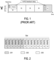
- FIG. 1 is a schematic diagram that illustrates an example of latency.
- D stands for downlink (DL)
- U stands for uplink (UL).
- the transmission directions for multiple timeslots are set as shown in FIG. 1 . That is whole severing cell is allocated for a single transmission direction within one timeslot.
- a base station may wait for three timeslots, and then a hybrid automatic repeat request (HARQ) feedback would be received on a physical uplink control channel (PUCCH). Furthermore, if UL data would like to be transmitted, the base station has to schedule a UL resource by a downlink control information (DCI) for the UL data, in which the UL resource is at a duration of four timeslots away from the timeslot where the DCI is scheduled, so as to UL latency issue.
- DCI downlink control information
- Exemplary embodiments of the disclosure provide a transmission direction setting method, a user equipment (UE), and a network device.
- UE user equipment
- a transmission direction setting method is adapted for a UE.
- the method comprises: receiving a first configuration to indicate a first transmission direction for a frequency range within a time unit; receiving a second configuration to indicate a second transmission direction for a frequency segmentation within the time unit; determining a third transmission direction for the frequency segmentation according to the second transmission direction.
- the frequency segmentation consists of one resource block (RB) or a set of consecutive RBs and is a part of the frequency range.
- a UE comprises a transceiver, a memory, and a processor.
- the transceiver is used for transmitting or receiving signals.
- the memory is used for storing a program code.
- the processor is coupled to the transceiver and the memory.
- the processor is configured for executing the program to: receive, through the transceiver, a first configuration to indicate a first transmission direction for a frequency range within a time unit; receive, through the transceiver, a second configuration to indicate a second transmission direction for a frequency segmentation within the time unit, where the frequency segmentation consists of one resource block (RB) or a set of consecutive RBs and is a part of the frequency range; and determine a third transmission direction for the frequency segmentation according to the second transmission direction.
- RB resource block
- a transmission direction setting method is adapted for a network device.
- the method comprises: transmitting a first configuration to indicate a first transmission direction for a frequency range within a time unit; transmitting a second configuration to indicate a second transmission direction for a frequency segmentation within the time unit; and determining a third transmission direction for the frequency segmentation according to the second transmission direction.
- the frequency segmentation consists of one resource block (RB) or a set of consecutive RBs and is a part of a frequency range.
- a network device comprises a transceiver, a memory, and a processor.
- the transceiver is used for transmitting or receiving signals.
- the memory is used for storing a program code.
- the processor is coupled to the transceiver and the memory.
- the processor is configured for executing the program to: transmit, through the transceiver, a first configuration to indicate a first transmission direction for a frequency range within a time unit; transmit, through the transceiver, a second configuration to indicate a second transmission direction for a frequency segmentation within the time unit, where the frequency segmentation consists of one resource block (RB) or a set of consecutive RBs and is a part of a frequency range; and determine a third transmission direction for the frequency segmentation according to the second transmission direction.
- RB resource block
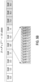
- FIG. 2 is a schematic diagram that illustrates a slot configuration.
- a slot format may include downlink (DL) symbols 201, flexible symbols 202, and uplink (UL) symbols 203.
- the following may be applicable for each serving cell: tdd-UL-DL-ConfigurationCommon (carried by radio resource control (RRC) message), tdd-UL-DL-ConfigurationDedicated (carried by RRC message), and slot format indicator (SFI)-Radio Network Temporary Identifier (RNTI) (carried by RRC message and used to receive downlink control information (DCI) such as DCI format 2_0).
- RRC radio resource control
- SFI slot format indicator
- RNTI Radio Network Temporary Identifier
- the tdd-UL-DL-ConfigurationCommon is a cell-specific configuration. If a UE is provided a higher layer parameter tdd-UL-DL-ConfigurationCommon, the UE may set the slot format per slot over a number of slots as indicated by the higher layer parameter tdd-UL-DL-ConfigurationCommon.
- the higher layer parameter tdd-UL-DL-ConfigurationCommon may provide: a reference subcarrier spacing configuration ⁇ _ref, a higher layer parameter pattern1, a slot configuration period P microsecond (ms) ( dl-UL-TransmissionPeriodicity ), the number of slots d slots with only downlink symbols ( nrofDownlinkSlots ) , the number of downlink symbols d_sym ( nrofDownlinkSymbols ), the number of slots u slots with only UL symbols ( nrofUplinkSlots ), and the number of uplink symbols u_sym ( nrofUplinkSymbols ) .
- FIG. 3 is a schematic diagram that illustrates a pattern pattern1 of tdd-UL-DL-ConfigurationCommon.
- S is the number of slots determined according to P and ⁇ _ref.
- the UE may set the slot format per slot over the first number of slots as indicated by pattern1 and the UE may set the slot format per slot over the second number of slots as indicated by pattern2.
- the higher layer parameter pattern2 may be provided with a slot configuration period P _2 ms ( dl-UL-TransmissionPeriodicity ) , the number of slots d_slots_2 with only downlink symbols ( nrofDownlinkSlots ) , the number of downlink symbols d_sym_2 ( nrofDownlinkSymbols ), the number of slots u_slots _ 2 with only UL symbols ( nrofUplinkSlots ), and the number of uplink symbols u_sym_2 ( nrofUplinkSymbols ).
- FIG. 4 is a schematic diagram that illustrates two patterns pattern1 and pattern2 of tdd-UL-DL-ConfigurationCommon.
- the tdd-UL-DL-ConfigurationDedicated is a UE-specific configuration. If the UE additionally provided tdd-UL-DL-ConfigurationDedicated, the parameter tdd-UL-DL-ConfigurationDedicated may override only flexible symbols per slot over the number of slots as provided by tdd-UL-DL-ConfigurationCommon.
- the higher layer parameter tdd-UL-DL-ConfigurationDedicated may provide: a slot index slotIndex ( TDD-UL-DL-SlotIndex ), the number of downlink symbols nrofDownlinkSymbols, and the number of uplink symbols nrofUplinkSymbols.
- FIG. 5A and FIG. 5B are schematic diagrams that show pattern change of tdd-UL-DL-ConfigurationDedicated.
- a UE receives tdd-UL-DL-ConfigurationCommon with parameters as described in FIG. 3 .
- nrofDownlinkSymbols 5
- nrofUplinkSymbols 3
- nrofUplinkSymbols 3
- DCI format 2_0 is a dynamic TDD indication. If a UE is configured by higher layers with a parameter SlotFormatIndicator, the UE may be provided an SFI-RNTI by SFI-RNTI and with a payload size of DCI format 2_0 by dci-PayloadSize.
- a SFI-index field value in a DCI format 2_0 may indicate to a UE a slot format for each slot in the number of slots starting from a slot where the UE detects the DCI format 2_0.
- the UE may not expect to detect a DCI format 2_0 with an SFI-index field value indicating the set of symbols of the slot as uplink/downlink, respectively, or as flexible. Therefore, the DCI format 2_0 would not override UL/DL symbols as provided by parameter tdd-UL-DL-ConfigurationCommon and/or tdd-UL-DL-ConfigurationDedicated, but may override flexible symbols.
- Table (1) is an example of a slot format table: Table (1) format 0 1 2 3 4 5 6 7 8 9 10 11 12 13 0 D D D D D D D D D D D 1 U U U U U U U U U U U U U U U U U U U U U U U U U U U U U U U U U U U U U U U U U U U U U U U U U U U U 2 F F F F F F F F F F F F F F F F F F F F F F F F F F F F F F F F F F F F F F F F F F F F F F F F F F F F F F F F F F F F F F F F F F F F F F F F F F F F F F F F F F F F F F F F F F F F F F F F F F F F F F F F F F F F F F F F F F F F F F F F F F F F F F F F F F F F F F F F F F F F F F F F F F F F F F F F F F F F
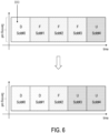
- FIG. 6 is a schematic diagram that illustrates transmission directions configurated by downlink control information (DCI).
- DCI downlink control information
- a UE may detect a DCI format 2_0 at timeslot slot#0, and a SFI-index field of the DCI format 2_0 may indicate "11" (i.e., Slot Format Combination: 0, 0, 2, 1).
- Timeslot slot#1 would be set as slot format "0" which is all DL symbols.
- Timeslot slot#2 would be set as slot format "2" which is all flexible symbols.
- Timeslot slot#1 would be set as slot format "1" which is all UL symbols.
- a UE may be configured with a flexible resource by higher layer configuration, and the UE may detect a DCI format 2_0 indicating a resource as flexible, then there are some reception limitations and/or transmission limitations.
- FIG. 7A is a schematic diagram that illustrates reception limitations of a flexible resource at DL part with detecting DCI format 2_0.
- the reception limitations for DL may be:
- FIG. 7B is a schematic diagram that illustrates transmission limitations of a flexible resource at UL part with detecting DCI format 2_0.
- the transmission limitations for UL may be:
- FIG. 8 is a schematic diagram that illustrates transmission and reception without detecting DCI format 2_0.
- a UE may be configured with a flexible resource by higher layer configuration, and the UE may not detect a DCI format 2_0 providing slot format for the flexible resource, then
- FIG. 9 is a schematic diagram that illustrates a communication system 100 according to an exemplary embodiment of the present disclosure.
- a communication system 100 e.g., a Long Term Evolution (LTE) system, an LTE-Advanced (LTE-A) system, an LTE-Advanced Pro system, or a 5G NR Radio Access Network (RAN)
- LTE Long Term Evolution
- LTE-A LTE-Advanced
- RAN 5G NR Radio Access Network
- the UE 120 communicates with the network (e.g., a Core Network (CN), an Evolved Packet Core (EPC) network, an Evolved Universal Terrestrial Radio Access network (E-UTRAN), a 5G Core (5GC), or an internet), through a RAN established by one or more network devices 110.
- the network e.g., a Core Network (CN), an Evolved Packet Core (EPC) network, an Evolved Universal Terrestrial Radio Access network (E-UTRAN), a 5G Core (5GC), or an internet
- CN Core Network
- EPC Evolved Packet Core
- E-UTRAN Evolved Universal Terrestrial Radio Access network
- 5GC 5G Core
- a UE may include, but is not limited to, a mobile station, a mobile terminal or device, a user communication radio terminal.
- a UE may be a portable radio equipment, which includes, but is not limited to, a mobile phone, a tablet, a wearable device, a sensor, a vehicle, or a Personal Digital Assistant (PDA) with wireless communication capability.
- PDA Personal Digital Assistant
- the UE is configured to receive and transmit signals over an air interface to one or more cells in a radio access network.
- a network device may be configured to provide communication services according to at least one of the following Radio Access Technologies (RATs): Worldwide Interoperability for Microwave Access (WiMAX), Global System for Mobile communications (GSM, often referred to as 2G), GSM Enhanced Data rates for GSM Evolution (EDGE) Radio Access Network (GERAN), General Packet Radio Service (GPRS), Universal Mobile Telecommunication System (UMTS, often referred to as 3G) based on basic wideband-code division multiple access (W-CDMA), high-speed packet access (HSPA), LTE, LTE-A, eLTE (evolved LTE, e.g., LTE connected to 5GC), NR (often referred to as 5G), and/or LTE-A Pro.
- RATs Radio Access Technologies
- WiMAX Worldwide Interoperability for Microwave Access
- GSM Global System for Mobile communications
- EDGERAN GSM Enhanced Data rates for GSM Evolution
- GPRS General Packet Radio Service
- UMTS Universal Mobile Telecommunication System
- a network device may include, but is not limited to, a node B (NB) as in the UMTS, an evolved node B (eNB) as in the LTE or LTE-A, a radio network controller (RNC) as in the UMTS, a base station controller (BSC) as in the GSM/ GSM Enhanced Data rates for GSM Evolution (EDGE) Radio Access Network (GERAN), a next-generation eNB (ng-eNB) as in an Evolved Universal Terrestrial Radio Access (E-UTRA) BS in connection with the 5GC, a next-generation Node B (gNB) as in the 5G Access Network (5G-AN), and any other apparatus capable of controlling radio communication and managing radio resources within a cell.
- the network device may connect to serve the one or more UEs through a radio interface to the network.
- the network device may be operable to provide radio coverage to a specific geographical area using a plurality of cells included in the RAN.
- the network device may support the operations of the cells.
- Each cell may be operable to provide services to at least one UE within its radio coverage.
- each cell (often referred to as a serving cell) may provide services to serve one or more UEs within its radio coverage (e.g., each cell schedules the Downlink (DL) and optionally Uplink (UL) resources to at least one UE within its radio coverage for DL and optionally UL packet transmission).
- the network device may communicate with one or more UEs in the radio communication system through the plurality of cells.
- the frame structure for NR is to support flexible configurations for accommodating various next generation (e.g., 5G) communication requirements, such as Enhanced Mobile Broadband (eMBB), Massive Machine Type Communication (mMTC), Ultra-Reliable and Low-Latency Communication (URLLC), while fulfilling high reliability, high data rate and low latency requirements.
- 5G next generation
- eMBB Enhanced Mobile Broadband
- mMTC Massive Machine Type Communication
- URLLC Ultra-Reliable and Low-Latency Communication
- OFDM Orthogonal Frequency-Division Multiplexing
- the scalable OFDM numerology such as the adaptive sub-carrier spacing, the channel bandwidth, and the Cyclic Prefix (CP) may also be used.
- two coding schemes are considered for NR: (1) Low-Density Parity-Check (LDPC) code and (2) Polar Code.
- the coding scheme adaption may be configured based on the channel conditions and/or the service applications.
- system and “network” used in the disclosure are often used interchangeably.
- the term “and/or” in the disclosure is only an association relationship describing the associated objects, which means that there can be three kinds of relationships, for example, A and/or B, which can mean three situations: A is present alone, A and B are present simultaneously, or B is present alone.
- the character "/" in the disclosure generally indicates that the associated objects are in an "or” relationship.
- FIG. 10 is a flow chart of a transmission direction setting method according to an exemplary embodiment of the present disclosure.
- the method is adapted for a UE.
- the UE receives a first configuration to indicate a first transmission direction for a frequency range within a time unit (S1010).
- the first configuration may be a higher layer configuration such as tdd-UL-DL-ConfigurationCommon, tdd-UL-DL-ConfigurationDedicated, or other configurations used for setting transmission direction.
- the first transmission direction may be, for example, DL, UL, flexible, or blank.
- the frequency range may be, for example, a serving cell, a sub-band such as BWP of the serving cell, or a range of resource blocks (RBs) provided by a network device.
- the time unit is one or more timeslots or one or more symbols.
- the UE receives a second configuration to indicate a second transmission direction for a frequency segmentation within the time unit (Step S1020).
- the second configuration may be a higher layer configuration such as tdd-UL-DL-ConfigurationDedicated, or other configurations used for setting transmission direction.
- the second configuration may be a downlink control information (DCI).
- DCI downlink control information
- the second transmission direction may be, for example, DL, UL, flexible, or blank.
- the frequency segmentation consists of one resource block (RB) or a set of consecutive RBs, and the frequency segmentation is a part of the frequency range. The frequency segmentation may be less than the frequency range.
- the UE determines a third transmission direction for the frequency segmentation according to the second transmission direction (Step S1030).
- the UE may determine the third transmission direction for the frequency segmentation as DL when the first transmission direction is flexible and the second transmission direction is DL, or when the first transmission direction is DL and the second transmission direction is DL, or when the first transmission direction is UL and the second transmission direction is DL. That is the third transmission direction is the second transmission direction (i.e., DL) no matter whether the first transmission direction is DL, UL or flexible.
- the UE may determine the third transmission direction for the frequency segmentation as UL when the first transmission direction is flexible and the second transmission direction is UL, or when the first transmission direction is UL and the second transmission direction is UL, or when the first transmission direction is DL and the second transmission direction is UL. That is the third transmission direction is the second transmission direction (i.e., UL) no matter whether the first transmission direction is DL, UL or flexible.
- the UE may determine the third transmission direction for the frequency segmentation as flexible, when the first transmission direction is flexible and the second transmission direction is flexible, or when the first transmission direction is UL and the second transmission direction is flexible, or when the first transmission direction is the DL and the second transmission direction is flexible. That is the third transmission direction is the second transmission direction (i.e., flexible) no matter whether the first transmission direction is DL, UL or flexible.
- the UE may determine the third transmission direction for the frequency segmentation as blank when the first transmission direction is flexible and the second transmission direction is blank, or when the first transmission direction is UL and the second transmission direction is blank, or when the first transmission direction is DL and the second transmission direction is blank. That is the third transmission direction is the second transmission direction (i.e., blank) no matter whether the first transmission direction is DL, UL or flexible.
- the second transmission direction may override the first transmission direction.
- the set of symbols of the slot may be indicated as uplink/downlink, respectively, or as flexible by a DCI format 2_0 with an SFI-index field. That is the DCI format 2_0 may override UL/DL symbols as provided by parameter tdd-UL-DL-ConfigurationCommon and/or tdd-UL-DL-ConfigurationDedicated.
- FIG. 11 is a schematic diagram that illustrates a transmission direction setting of a first configuration according to an exemplary embodiment of the present disclosure.
- the transmission directions of timeslots TU of UE1 would be set as DL, flexible, flexible, and UL, respectively, for the whole frequency range FR.
- the transmission directions of timeslots TU of UE2 would also be set as DL, flexible, flexible, and UL, respectively.
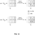
- FIG. 12 is a schematic diagram that illustrates a transmission direction setting of a second configuration according to an exemplary embodiment of the present disclosure.
- the frequency range FR used for UE1 and UE2 may be split within one timeslot TU.
- FIG. 13 is a schematic diagram that illustrates frequency segmentations according to an exemplary embodiment of the present disclosure.
- the frequency range FR may be split into two frequency segmentations FS1 and FS2 within a timeslot TU. That is the frequency range FR consists of frequency segmentations FS1 and FS2.
- the second configuration further indicates a fourth transmission direction for another frequency segmentation within the time slot.
- An overlap between the frequency segmentation and the another frequency segmentation is absent in the frequency domain. That is two frequency segmentations are not overlapped in the frequency domain.
- a UE may determine a fifth transmission direction for the another frequency segmentation according to the fourth transmission direction.
- the fifth transmission direction is the fourth transmission direction no matter whether the first transmission direction is DL, UL or flexible.
- the fifth transmission direction is the first transmission direction in which the first transmission direction is DL or UL.
- the network device configures that the frequency range FR is split into two frequency segmentations.
- the first transmission direction is configured as flexible.
- the second transmission direction of the second configuration may override the first transmission direction of the first configuration. That is, the first transmission direction is replaced by the second transmission direction and the fourth transmission direction.
- the third transmission directions are DL (i.e., the second transmission direction) and flexible (i.e., the fourth transmission direction) within a timeslot TU.
- the fifth transmission directions are flexible (i.e., the second transmission direction) and UL (i.e., the fourth transmission direction) within a timeslot TU.
- the network device may specify a resource in which a UE may not perform DL reception and/or UL transmission.
- a resource in which a UE may not perform DL reception and/or UL transmission.
- the UE in order to receive reference signals such as DL PRS or transmit reference signals such as SRS, the UE may not perform DL reception and/or UL transmission.
- one frequency range may consist of more than two frequency segmentations. Then, more than two transmission directions may be configured for a time unit.
- the UE may determine the third transmission direction for the frequency segmentation as UL, when the first transmission direction is DL for a frequency range and the second transmission direction is UL for a frequency seqmentation of the frequency range. That is the first transmission direction is replaced by the second transmission direction.
- the UE may determine the third transmission direction for the frequency segmentation as DL, when the first transmission direction is UL for a frequency range and the second transmission direction is DL for a frequency seqmentation of the frequency range. That is the first transmission direction is replaced by the second transmission direction.
- the frequency segmentation occupies a range from a first RB to a second RB
- the first RB and the second RB are with reference to common resource block (CRB) grid
- the second configuration comprises at least one of an RB index of the first RB and an RB index of the second RB.
- a UE may be provided, for example, by higher layer, by DCI indication, one or more RB indexes. These RB indexes may be applied to a frequency range, for example, a serving cell or a BWP of the serving cell.
- FIG. 14 is a schematic diagram that illustrates frequency segmentations indicated by resource block (RB) indexes according to an exemplary embodiment of the present disclosure.
- a UE may be configured with a frequency range FR such as a serving cell from resource block RB#0 (i.e., the first RB) to resource block RB#99 (i.e., the second RB).
- the second configuration indicates RB index 50 corresponding to resource block RB#50. Therefore, the first frequency segmentation FS 12 occupies from resource block RB#0 to resource block RB#49, and the second frequency segmentation FS22 occupies from resource block RB#50 to resource block RB#99.
- a UE may set the slot format per slot over a number of slots as indicated by tdd-UL-DL-ConfigurationCommon.
- a UE may be configured a parameter of tdd-UL-DL-ConfigurationDedicated_duplex, wherein the parameter may comprise at least one of following:
- the RB index field indicated by the second configuration is a starting RB of one frequency segmentation.
- FIG. 15A is a schematic diagram that illustrates a transmission direction setting of tdd-UL-DL-ConfigurationCommon with RB indexes according to an exemplary embodiment of the present disclosure.
- tdd-UL-DL-ConfigurationCommon configures transmission directions of three timeslot TU for the whole frequency range FR from resource block RB#N (i.e., the highest RB index of the frequency range FR) to resource block RB#M (i.e., the lowest RB index of the frequency range FR).
- M and N are integers. For example, N is 0, and M is 99.
- FIG. 15B is a schematic diagram that illustrates a transmission direction setting of tdd-UL-DL-ConfigurationDedicated_duplex with RB indexes according to an exemplary embodiment of the present disclosure.
- UL-DL-ConfigurationDedicated_duplex configures transmission directions of one timeslot TU as flexible and DL with RB index field set as L in which one frequency segmentation occupies from resource block RB#N to resource block RB#L-1 and another frequency segmentation occupies from resource block RB#L to resource block RB#M.
- L is an integer not larger than M and not smaller than N. For example, if N is 0 and M is 99, L could be 70.
- the one frequency segmentation is configured as flexible and the another frequency segmentation is configured as DL.
- FIG. 15C is a schematic diagram that illustrates a transmission direction setting of tdd-UL-DL-ConfigurationDedicated_duplex with the lowest RB index according to an exemplary embodiment of the present disclosure.
- UL-DL-ConfigurationDedicated_duplex configures transmission directions of one timeslot TU as flexible and DL with RB index field set as N (e.g., 0) in which no frequency segmentation is generated from resource block RB#N to resource block RB#M (M is, for example, 99) and the frequency range FR is configured as DL.
- N e.g., 0
- M is, for example, 99
- FIG. 15D is a schematic diagram that illustrates a transmission direction setting of tdd-UL-DL-ConfigurationDedicated_duplex with the highest RB index according to an exemplary embodiment of the present disclosure.
- UL-DL-ConfigurationDedicated_duplex configures transmission directions of one timeslot TU as flexible and DL with RB index field set as M (e.g., 99) in which no frequency segmentation is generated from resource block RB#N (M is, for example, 0) to resource block RB#M and frequency range FR is configured as flexible.
- M e.g. 99
- FIG. 15E is a schematic diagram that illustrates a transmission direction setting of tdd-UL-DL-ConfigurationCommon for bandwidth parts (BWPs) according to an exemplary embodiment of the present disclosure.
- the frequency range FR includes bandwidth parts BWP#1 and BWP#2.
- FIG. 15F is a schematic diagram that illustrates a transmission direction setting of tdd-UL-DL-ConfigurationDedicated for BWP according to an exemplary embodiment of the present disclosure.
- a network device and a UE may operate a full duplex in bandwidth part BWP#1 in which the bandwidth part BWP#1 is configured with DL and flexible.
- a (e.g., DL and/or UL) BWP in the disclosure may be a contiguous set of PRB(s) on a given carrier.
- UE can be configured with maximum 4 BWP for Downlink and Uplink but at a given point of time only one BWP is active for downlink and one for uplink.
- Each BWP defined for a numerology may have different Subcarrier spacing, Symbol duration and/or Cyclic prefix (CP) length.
- FIG. 16 is a schematic diagram that illustrates a resource allocation with multiple flexible resources for BWP according to an exemplary embodiment of the present disclosure.
- a UE may operate in a bandwidth part BWP#1, and the UE may have a first flexible resource and a second flexible resource in the bandwidth part BWP#1.
- the UE may not expect that the first flexible resource and the second flexible resource are discontinuous in the frequency domain.
- the following may be applicable for a frequency range such as a serving cell. If a UE is provided tdd-UL-DL-ConfigurationCommon, the UE may set the slot format per slot over a number of slots as indicated by tdd-UL-DL-ConfigurationCommon. If the UE is additionally provided tdd-UL-DL-ConfigurationDedicated, the parameter tdd-UL-DL-ConfigurationDedicated may override only flexible symbols per slot over the number of slots as provided by tdd-UL-DL-ConfigurationCommon.
- FIG. 17A is a schematic diagram that illustrates a slot format indication by tdd-UL-DL-ConfigurationCommon according to an exemplary embodiment of the present disclosure.
- tdd-UL-DL-ConfigurationCommon i.e., the first configuration
- the transmission directions of timeslots TU would be set as DL, flexible, and UL, respectively, for the whole frequency range FR.
- FIG. 17B is a schematic diagram that illustrates a slot format indication by tdd-UL-DL-ConfigurationDedicated according to an exemplary embodiment of the present disclosure. Referring to FIG.
- tdd-UL-DL-ConfigurationDedicated i.e., the second configuration
- the transmission direction of a timeslot TU would be set as DL. That is the flexible resource provided by tdd-UL-DL-ConfigurationCommon may be overridden as DL resource by dd-UL-DL-ConfigurationDedicated.
- a UE may be configured with a frequency range such as a serving cell, and the UE may operate in a BWP within the serving cell.
- the UE may detect a DCI, for example, DCI format 2_0, in the BWP, and the DCI may comprise one or more pieces of the following information which may be applied to the frequency range:
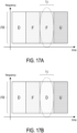
- FIG. 18A to FIG. 18C are schematic diagrams that illustrate a slot format indication by DCI format 2_0 according to an exemplary embodiment of the present disclosure.
- a UE may detect a DCI format 2_0 in a bandwidth part BWP at timeslot slot#1.
- the DCI format 2_0 may include at least one of the following information: RB index field, for example, RB index 50, and transmission state/direction, for example, flexible and DL.
- the information is used for the whole frequency range FR within a time unit TU1 such as timeslot slot#2 configured as flexible. Therefore, in a time unit TU1 including symbol#0 to symbol#13, two frequency segmentations would be configured as flexible and DL.
- a network device and the UE may operate full-deplex in the bandwidth part BWP.
- a UE may detect a DCI, e.g., DCI format 2_0, in the BWP, and the DCI may comprise one or more pieces of the following information which may be applied to the BWP:
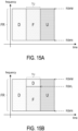
- FIG. 19A and FIG. 19B are schematic diagrams that illustrate a slot format indication by DCI format 2_0 for BWP according to an exemplary embodiment of the present disclosure.
- a UE may detect a DCI format 2_0 in a bandwidth part BWP at timeslot slot#1.
- the DCI format 2_0 may include at least one of the following information: RB index field, for example, RB index 80, and transmission state/direction, for example, flexible and DL.
- the information is used for the bandwidth part BWP#1 within a time unit TU2 such as timeslot slot#2 configured as flexible. Therefore, in a time unit TU2 including symbol#0 to symbol#13, two frequency segmentations would be configured as flexible and DL.
- a UE may configure a slot format table.
- the slot format table includes multiple transmission directions for a symbol, and the number of these transmission directions is associated with the number of frequency segmentations.
- a UE may be configured with an enhanced slot format table, and the UE may detect a DCI, for example, DCI format 2_0.
- Each row of the enhanced slot format table may indicate a slot format for a time unit such as a slot.
- the number of columns of the enhanced slot format table may be 14 ⁇ a , where the value of a may be associated with the RB index field of the DCI, for example, the value of a may be the same as the number of RB indexes provided by the RB index field + 1.
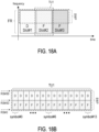
- FIG. 20A is a schematic diagram that illustrates an enhanced slot format table according to an exemplary embodiment of the present disclosure.
- the number of frequency segmentations is 2, and the number of these transmission directions is 2 (i.e., a ) .
- the number of columns of the enhanced slot format table is 2 ⁇ 14. That is the number of frequency segmentations equals the number of these transmission directions.
- two transmission directions are configured as flexible and DL.
- a UE may detect a DCI format 2_0, and the RB index field of the DCI format 2_0 may include "RB index 50".
- a frequency range FR is split into two frequency segmentations configured as DL from resource block RB#50 to resource block RB#99 and flexible from resource block RB#0 to resource block RB#49.
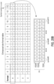
- FIG. 20B is a schematic diagram that illustrates another enhanced slot format table according to an exemplary embodiment of the present disclosure.
- the number of frequency segmentations is 2, and the number of these transmission directions is 2 (i.e., a ).
- the number of columns of the enhanced slot format table is 2 ⁇ 14. That is the number of frequency segmentations equals the number of these transmission directions.
- two transmission directions are configured as flexible and DL.
- a UE may detect a DCI format 2_0, and the RB index field of the DCI format 2_0 may include "RB index 50".
- a frequency range FR is split into two frequency segmentations configured as DL from resource block RB#50 to resource block RB#99 and flexible from resource block RB#0 to resource block RB#49.
- a UE may configure a slot format combination table. At least two values within the slot format combination table are used for a slot, and the number of the at least two values is associated with the number of frequency segmentations.
- a UE may be configured with a slot format combination table, and the UE may detect a DCI, for example, DCI format 2_0, and the number of RB indexes provided by RB index field of the DCI may be X.
- the number of values in the SlotFormatCombination may be at least equal to X + 1.
- the number of values in the SlotFormatCombination may be an integer multiple of (X + 1). Per (X+1) values in the SlotFormatCombination may indicate a slot format for a time unit such as a slot.
- table (2) is an example of a slot format combination table.
- the slot format combination is a combination of multiple slot formats.
- table (3) is an another example of a slot format combination table.
- Table (3) SlotFormatCombinationID SlotFormatCombination 0 2, 0 1 0, 0, 0, 2 2 0, 1, 2, 3 3 0, 0, 2, 2
- "2, 0” means a combination of the slot format "2" and the slot format "0" as shown in the table (1). Taking 2 values for a slot, the first value, i.e., "2", is applied from RB#0 to RB#49, the second value, i.e., "0”, is applied from RB#50 to RB#99.
- FIG. 21A is a schematic diagram that illustrates a blank source according to an exemplary embodiment of the present disclosure.
- a UE may be indicated, for example, by RRC configuration, by DCI indication, by MAC CE indication, by predefined, a resource as blank (resource).
- the blank resource may be a time domain resource, a frequency domain resource, a spatial domain resource, a time and frequency domain resource, a time and spatial domain resource, or a frequency and spatial domain resource.
- a UE may mute a DL reception and/or a UL transmission within the frequency segmentation when the third transmission direction for the frequency segmentation is determined as blank. That is the UE may not perform DL reception and/or UL transmission in the blank resource.
- FIG. 21B is a schematic diagram that illustrates a reception limitation on a blank source according to an exemplary embodiment of the present disclosure.
- a network device may not override the blank resource to DL resource, and the UE may not expect to detect information, for example, by RRC configuration, by DCI indication, overriding the blank resource to other resources, for example, DL resource, UL resource or Flexible resource.
- a UE may receive a blank pattern.
- the blank pattern indicates whether one of a set of time units is determined as blank.
- a UE may be provided, for example, by higher layer or by DCI indication, a blank pattern.
- the UE may not perform DL reception in a resource, if the resource associated with the blank pattern indicating "enable” or "true", for example, the blank pattern may indicate '1' to the resource.
- the UE may not perform UL transmission in a resource, if the resource associated with the blank pattern indicating "enable” or "true", for example, the blank pattern may indicate ⁇ 1' to the resource.
- UE may perform DL reception or UL transmission in a resource, if the resource associated with the blank pattern indicating "disable” or "false", for example, the blank pattern may indicate '0' to the resource.
- FIG. 22 is a schematic diagram that illustrates a blank pattern according to an exemplary embodiment of the present disclosure.
- the black pattern is ⁇ 1 0 0 1 ⁇ .
- a UE may not perform DL PRS reception in which its blank pattern indicates '1'.
- the UE may perform SRS transmission in which its blank pattern indicates ⁇ 0'.
- the UE may perform DL PRS reception in which its blank pattern indicates '0'.
- the UE may not perform SRS transmission in which its blank pattern indicates '1'.
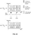
- FIG. 23 is a schematic diagram that illustrates another blank pattern according to an exemplary embodiment of the present disclosure.
- the black pattern is ⁇ 0 1 0 0 0 0 0 0 ⁇ .
- UE1 may not perform DL PRS reception in which its blank pattern indicates '1'.
- UE1 may perform SRS transmission in which its blank pattern indicates ⁇ 0'.
- FIG. 24 is a schematic diagram that illustrates a transmission direction setting according to an exemplary embodiment of the present disclosure.
- a UE may disable receiving a DL signal when the transmission direction for the frequency segmentation is determined as flexible and a duplex mode is configured.
- the DL signal may be, for example, DL PRS or PDCCH.
- the duplex mode is configured when multiple frequency segmentations are configured as different transmission directions within a time unit.
- a UE may be configured with a flexible resource by higher layer configuration (i.e., the first configuration), and the UE may detect a DCI format 2_0 (i.e., the second configuration) indicating a resource as a flexible resource, and the UE is configured by higher layers to receive DL PRS in the flexible resource. However, the UE may not receive the DL PRS in the flexible resource, if the UE is configured with duplex_mode.
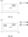
- FIG. 25 is a schematic diagram that illustrates a reception limitation on a flexible resource according to an exemplary embodiment of the present disclosure.
- a UE is configured with duplex mode.
- a resource may be indicated as a flexible resource by a higher layer configuration.
- the resource may be indicated as a flexible resource by DCI format 2_0. Then, if the flexible resource is configured, the UE may not receive DL PRS.
- a UE may be configured with a flexible resource by higher layer configuration, but the UE may not detect a DCI format 2_0 providing slot format for the flexible resource.
- the UE may not receive PDCCH in the flexible resource if the UE is configured with duplex _mode.
- the UE may not receive the DL PRS in the flexible resource, if the UE is configured with duplex_mode.
- FIG. 26 is a schematic diagram that illustrates another reception limitation on a flexible resource according to an exemplary embodiment of the present disclosure.
- a UE is configured with duplex mode.
- a resource may be indicated as a flexible resource by a higher layer configuration.
- the UE may miss DCI format 2_0. Then, if the flexible resource is configured, the UE may not receive DL PRS and/or PDCCH.
- a UE may disable transmitting an UL signal when the transmission direction for the frequency segmentation is determined as flexible and a duplex mode is configured.
- the UL signal may be, for example, SRS, PUCCH, PUSCH, or PRACH.
- a UE may be configured with a flexible resource by higher layer configuration, and the UE may not detect a DCI format 2_0 providing slot format for the flexible resource.
- the UE may not transmit SRS in the flexible resource if the UE is configured with duplex _mode.
- the UE may not transmit PUCCH in the flexible resource if the UE is configured with duplex_mode.
- the UE may not transmit PUSCH in the flexible resource if the UE is configured with duplex_mode.
- the UE may not transmit PRACH in the flexible resource if the UE is configured with duplex_mode. It should be noted that the UE may be provided enableConfiguredUL.
- FIG. 27 is a schematic diagram that illustrates a transmission limitation on a flexible resource according to an exemplary embodiment of the present disclosure.
- a UE is configured with duplex mode.
- a resource may be indicated as a flexible resource by a higher layer configuration.
- the UE may miss DCI format 2_0. Then, if the flexible resource is configured, the UE may not transmit SRS, PUCCH, PUSCH, and/or PRACH.
- FIG. 28 is a schematic diagram that illustrates a transmission direction setting for BWP according to an exemplary embodiment of the present disclosure.
- the aforementioned second configuration could be BWP/sub-band-specific configuration.
- a UE may be configured a first sub-band, for example, a first BWP, and a second sub-band, for example, a second BWP, within a frequency range, for example, a serving cell.
- the UE may be configured with a parameter of tdd-UL-DL-ConfigurationDedicated_first_sub-band (i.e., the second configuration), and the parameter may override only flexible symbols per slot over the number of slots as provided by tdd-UL-DL-ConfigurationCommon (i.e., the first configuration) in the first sub-band.
- the UE may be configured with a parameter of tdd-UL-DL-ConfigurationDedicated_second_ sub-band (i.e., the second configuration), and the parameter may override only flexible symbols per slot over the number of slots as provided by tdd-UL-DL-ConfigurationCommon (i.e., the first configuration) in the second sub-band.
- tdd-UL-DL-ConfigurationDedicated_second_ sub-band i.e., the second configuration
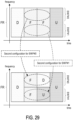
- FIG. 29 is a schematic diagram that illustrates a BWP-specific UL-DL configuration according to an exemplary embodiment of the present disclosure.
- tdd-UL-DL-ConfigurationCommon i.e., the first configuration
- the second configuration for BWP#0 could be tdd-UL-DL-ConfigurationDedicated_first_sub-band
- the second configuration for BWP#1 could be tdd-UL-DL-ConfigurationDedicated_second_sub-band.
- a UE may communicate with a network device in a first BWP, for example, an active BWP, and may detect a DCI format 2_0 in the first BWP within a frequency range, for example, a serving cell.
- An SFI-index field of the DCI format 2_0 may be applied for the first BWP only.
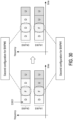
- FIG. 30 is a schematic diagram that illustrates a BWP-specific slot format indicator (SFI) configuration according to an exemplary embodiment of the present disclosure.
- a UE may detect DCI format 2_0 in bandwidth part BWP#0.
- the second configuration for BWP#0 could be DCI format 2_0 for BWP#0 including a SFI-index field.
- the SFI-index field of DCI format 2_0 for BWP#0 may override flexible resource to DL resource.
- the SFI-index field of DCI format 2_0 for BWP#0 may not be applied to the bandwidth part BWP#1.
- Merely second configuration for BWP#1 may be applied to the bandwidth part BWP#1.
- the following may be applicable for a frequency range such as a serving cell. If a UE is provided tdd-UL-DL-ConfigurationCommon, the UE may set the slot format per slot over a number of slots as indicated by tdd-UL-DL-ConfigurationCommon. If the UE is additionally provided tdd-UL-DL-ConfigurationDedicated, the parameter tdd-UL-DL-ConfigurationDedicated may override only flexible symbols per slot over the number of slots as provided by tdd-UL-DL-ConfigurationCommon. It means that the third transmission direction would be the second direction only when the first transmission direction is flexible.
- FIG. 31A and FIG. 31B are schematic diagrams that illustrate cell-specific/UE-specific UL-DL configuration according to an exemplary embodiment of the present disclosure.
- the flexible resource provided by tdd-UL-DL-ConfigurationCommon may be overridden as DL resource by tdd-UL-DL-ConfigurationDedicated.
- a UE may be configured with a first BWP and a second BWP, and the UE may operate in the first BWP, for example, an active BWP.
- the UE may detect a DCI format 2_0 (i.e., the second configuration) in the first BWP, and the SFI-index field of the DCI format 2_0 may indicate slot format separately for the first BWP and the second BWP.
- FIG. 32 is a schematic diagram that illustrates a dynamic indication according to an exemplary embodiment of the present disclosure.
- a UE may detect DCI format 2_0 in bandwidth part BWP#0, and the SFI-index field may include first information, for example, indicating overriding flexible resource to DL resource, applied to BWP#0 and second information, for example, indicating overriding flexible resource to UL resource, applied to BWP#1.
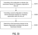
- FIG. 33 is a flow chart of a transmission direction setting method according to an exemplary embodiment of the present disclosure.
- the method is adapted for a network device.
- the network device transmits a first configuration to indicate a first transmission direction for a frequency range within a time unit (S3310).
- the first configuration may be a higher layer configuration such as tdd-UL-DL-ConfigurationCommon, tdd-UL-DL-ConfigurationDedicated, or other configurations used for setting transmission direction.
- the first transmission direction may be, for example, DL, UL, flexible, or blank.
- the frequency range may be, for example, a serving cell, a sub-band such as BWP of the serving cell, or a range of resource blocks (RBs) provided by a network device.
- the time unit is one or more timeslots or one or more symbols.
- the network device transmits a second configuration to indicate a second transmission direction for a frequency segmentation within the time unit (Step S3320).
- the second configuration may be a higher layer configuration such as tdd-UL-DL-ConfigurationDedicated, or other configurations used for setting transmission direction.
- the second configuration may be a downlink control information (DCI).
- DCI downlink control information
- the second transmission direction may be, for example, DL, UL, flexible, or blank.
- the frequency segmentation consists of one resource block (RB) or a set of consecutive RBs, and the frequency segmentation is a part of the frequency range. The frequency segmentation may be less than the frequency range.
- the network device determines a third transmission direction for the frequency segmentation according to the second transmission direction (Step S3330).
- the network device may determine the third transmission direction for the frequency segmentation as DL when the first transmission direction is flexible and the second transmission direction is DL, or when the first transmission direction is DL and the second transmission direction is DL, or when the first transmission direction is UL and the second transmission direction is DL.
- the network device may determine the third transmission direction for the frequency segmentation as UL when the first transmission direction is flexible and the second transmission direction is UL, or when the first transmission direction is UL and the second transmission direction is UL, or when the first transmission direction is DL and the second transmission direction is UL.
- the network device may determine the third transmission direction for the frequency segmentation as flexible, when the first transmission direction is flexible and the second transmission direction is flexible, or when the first transmission direction is UL and the second transmission direction is flexible, or when the first transmission direction is the DL and the second transmission direction is flexible.
- the network device may determine the third transmission direction for the frequency segmentation as blank when the first transmission direction is flexible and the second transmission direction is blank, or when the first transmission direction is UL and the second transmission direction is blank, or when the first transmission direction is DL and the second transmission direction is blank.
- the frequency segmentation occupies a range from a first RB to a second RB
- the first RB and the second RB are with reference to common resource block (CRB) grid
- the second configuration comprises at least one of an RB index of the first RB and an RB index of the second RB.
- the second configuration further indicates a fourth transmission direction for another frequency segmentation within the time slot, and an overlap between the frequency segmentation and the another frequency segmentation is absent in frequency domain.
- the network device may determine a fifth transmission direction for the another frequency segmentation according to the fourth transmission direction.
- a network device may configure a slot format table, wherein the slot format table comprises a plurality of transmission directions for a symbol, and a number of the plurality of transmission directions is associated with a number of frequency segmentations.
- a network device may configure a slot format combination table, wherein at least two values within the slot format combination table are used for a slot, and a number of the at least two values is associated with a number of frequency segmentations.
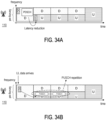
- FIG. 34A is a schematic diagram that illustrates latency reduction according to an exemplary embodiment of the present disclosure.
- a network device of embodiments of the present disclosure may wait for merely one timeslot, and then HARQ feedback would be received on a PUCCH. Therefore, the latency of feedback delay may be reduced.
- FIG. 34B is a schematic diagram that illustrates scheduling reduction and coverage enhancement according to an exemplary embodiment of the present disclosure.
- a network device of embodiments of the presnt disclosure may schedule an UL resource by a DCI for the UL data, in which the UL resource is at a duration of one timeslot away from the timeslot where the DCI is scheduled, so as to reduce UL scheduling delay.
- PUSCH repetition could be provided to enhance UL coverage.
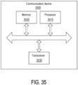
- FIG. 35 is a block diagram that illustrates a communication device 3500 according to an exemplary embodiment of the present disclosure.
- the communication device 3500 may be a UE or a network device.
- the communication device 3500 may include, but is not limited thereto a processor 3510.
- the processor 3510 e.g., having processing circuitry
- the processor 3510 may include an intelligent hardware device, e.g., a Central Processing Unit (CPU), a microcontroller, an ASIC, and etc.
- the processor 3510 can call and run a computer program from a memory to implement the method in the embodiment of the disclosure.
- the program code stored in the communication device 3500 adopts all the technical solutions of all the foregoing embodiments when being executed by the processor 3510, it at least has all the advantageous effects brought by all the technical solutions of all the foregoing embodiments, and no further description is incorporated herein.
- the communication device 3500 may further include a memory 3520.
- the memory 3500 may include computer-storage media in the form of volatile and/or non-volatile memory.
- the memory 3500 may be removable, non-removable, or a combination thereof.
- Exemplary memory includes solid-state memory, hard drives, optical-disc drives, and etc.
- the processor 3510 may call and run a computer program from the memory 520 to implement the method in the embodiment of the disclosure.
- the memory 3520 may be a separate device independent of the processor 3510, or may be integrated in the processor 3510.
- the communication device 3500 may further include a transceiver 3530, and the processor 3510 may control the transceiver 3530 to communicate with other devices.
- the transceiver 3500 having a transmitter (e.g., transmitting/transmission circuitry) and a receiver (e.g., receiving/reception circuitry) may be configured to transmit and/or receive time and/or frequency resource partitioning information.
- the transceiver 3500 may be configured to transmit in different types of subframes and slots including, but not limited to, usable, non-usable and flexibly usable subframes and slot formats.
- the transceiver 3500 may be configured to receive data and control channels.
- the transceiver 3530 may send information or data to other devices, or receive information or data sent by other devices.
- the transceiver 3530 may include a transmitter and a receiver.
- the transceiver 3530 may further include an antenna, and the number of antennas may be one or more.
- the communication device 3500 may specifically be a network device in an embodiment of the disclosure, and the communication device 3500 may implement the corresponding process implemented by the network device in various methods of the embodiment of the disclosure. For the conciseness, related descriptions are omitted.
- the communication device 3500 may specifically be a mobile terminal, a terminal device, or a UE in an embodiment of the disclosure, and the communication device 3500 may implement the corresponding process implemented by the mobile terminal, the terminal device, or the UE in various methods in the embodiment of the disclosure. For conciseness, related description is omitted.
- a frequency range such as a serving cell or a BWP of the serving cell
- a second configuration such as a higher layer configuration or DCI may override parameters provided by a first configuration. Therefore, UL coverage may be enhanced, feedback or scheduling latency may be reduced, and configuration flexibility for NR TDD operation in an unpaired spectrum may be improved.
Landscapes
- Engineering & Computer Science (AREA)
- Signal Processing (AREA)
- Computer Networks & Wireless Communication (AREA)
- Mobile Radio Communication Systems (AREA)
- Small-Scale Networks (AREA)
- Communication Control (AREA)
Applications Claiming Priority (2)
| Application Number | Priority Date | Filing Date | Title |
|---|---|---|---|
| US202263336229P | 2022-04-28 | 2022-04-28 | |
| US18/302,000 US20230354283A1 (en) | 2022-04-28 | 2023-04-18 | Transmission direction setting method, user equipment, network device |
Publications (2)
| Publication Number | Publication Date |
|---|---|
| EP4270847A2 true EP4270847A2 (de) | 2023-11-01 |
| EP4270847A3 EP4270847A3 (de) | 2023-11-08 |
Family
ID=86226296
Family Applications (1)
| Application Number | Title | Priority Date | Filing Date |
|---|---|---|---|
| EP23169745.9A Pending EP4270847A3 (de) | 2022-04-28 | 2023-04-25 | Verfahren zur einstellung der übertragungsrichtung, benutzergerät, netzwerkvorrichtung |
Country Status (6)
| Country | Link |
|---|---|
| US (1) | US20230354283A1 (de) |
| EP (1) | EP4270847A3 (de) |
| JP (1) | JP7628151B2 (de) |
| KR (1) | KR20230153290A (de) |
| AU (1) | AU2023202524B2 (de) |
| TW (1) | TWI857582B (de) |
Families Citing this family (2)
| Publication number | Priority date | Publication date | Assignee | Title |
|---|---|---|---|---|
| MX2023014625A (es) * | 2022-06-13 | 2024-01-17 | Zte Corp | Método, dispositivo, y sistema para transmisión de señal y de datos en redes inalámbricas. |
| US20250266975A1 (en) * | 2024-02-15 | 2025-08-21 | Qualcomm Incorporated | Sbfd-aware ue behavior in sfi-fl symbol with ul-sb |
Family Cites Families (9)
| Publication number | Priority date | Publication date | Assignee | Title |
|---|---|---|---|---|
| CN108632193B (zh) * | 2017-03-24 | 2023-05-09 | 华为技术有限公司 | 一种资源指示方法及网络设备、终端设备 |
| US10659151B2 (en) | 2017-04-21 | 2020-05-19 | Apple Inc. | Apparatus, system and method for utilizing a flexible slot format indicator |
| ES2913261T3 (es) * | 2017-04-21 | 2022-06-01 | Huawei Tech Co Ltd | Procedimiento y dispositivo para configurar la dirección de transmisión de recursos de tiempo-frecuencia |
| EP3769574A4 (de) * | 2018-05-22 | 2021-05-19 | Samsung Electronics Co., Ltd. | Verfahren zur ressourcenkonfiguration und vorrichtung und speichermedium dafür |
| JPWO2020016933A1 (ja) | 2018-07-17 | 2021-08-12 | 株式会社Nttドコモ | 基地局 |
| CN110740517A (zh) * | 2018-07-20 | 2020-01-31 | 华硕电脑股份有限公司 | 用于在无线通信系统中决定时隙格式的方法和设备 |
| CN112713976A (zh) | 2019-10-25 | 2021-04-27 | 北京三星通信技术研究有限公司 | 用于ue的信号传输方法及装置 |
| US12267819B2 (en) * | 2020-01-25 | 2025-04-01 | Qualcomm Incorporated | Complexity reduction for slot format determination |
| GB2628280A (en) * | 2021-12-10 | 2024-09-18 | Lenovo Beijing Ltd | Methods and apparatus of determining format of uplink and downlink transmissions for full duplex time division duplex |
-
2023
- 2023-04-18 US US18/302,000 patent/US20230354283A1/en active Pending
- 2023-04-25 EP EP23169745.9A patent/EP4270847A3/de active Pending
- 2023-04-25 JP JP2023071211A patent/JP7628151B2/ja active Active
- 2023-04-26 TW TW112115536A patent/TWI857582B/zh active
- 2023-04-26 AU AU2023202524A patent/AU2023202524B2/en active Active
- 2023-04-26 KR KR1020230054388A patent/KR20230153290A/ko active Pending
Also Published As
| Publication number | Publication date |
|---|---|
| JP2023164349A (ja) | 2023-11-10 |
| KR20230153290A (ko) | 2023-11-06 |
| AU2023202524A1 (en) | 2023-11-16 |
| EP4270847A3 (de) | 2023-11-08 |
| US20230354283A1 (en) | 2023-11-02 |
| TW202344134A (zh) | 2023-11-01 |
| JP7628151B2 (ja) | 2025-02-07 |
| AU2023202524B2 (en) | 2024-12-19 |
| TWI857582B (zh) | 2024-10-01 |
Similar Documents
| Publication | Publication Date | Title |
|---|---|---|
| KR102379039B1 (ko) | 무선 통신 시스템에서 랜덤 액세스 절차를 수행하는 방법 및 장치 | |
| US11252713B2 (en) | Downlink control information receiving method and user equipment, and downlink control information transmitting method and base station | |
| US11212800B2 (en) | Method and apparatus for communication in wireless communication system | |
| CN109479306B (zh) | 用户设备、基站和方法 | |
| EP3179644B1 (de) | Verfahren zur übertragung eines uplink-signals und benutzergerät und verfahren zum empfangen eines uplink-signals und basisstation | |
| EP3172856B1 (de) | Verfahren und benutzervorrichtung zum empfang von downlink-steuerinformationen sowie verfahren und basisstation zum senden von downlink-steuerinformationen | |
| EP3355646B1 (de) | Verfahren zum senden und empfangen von daten in einem unlizenzierten band und vorrichtung dafür | |
| EP2884678B1 (de) | Verfahren für den empfang eines downlink-steuerkanals in einem drahtlosen kommunikationssystem | |
| EP3771115B1 (de) | Verfahren und vorrichtung zur übertragung eines drahtlosen signals in einem drahtloskommunikationssystem | |
| EP2806573A1 (de) | Verfahren zum senden/empfangen von steuerinformationen und vorrichtung dafür | |
| WO2019141101A1 (zh) | 随机接入方法及装置 | |
| KR102332313B1 (ko) | 비면허 대역의 무선 통신을 위한 LBT(Listen Before Talk)를 수행하는 방법 및 장치 | |
| CN114080851B (zh) | 在非许可频段中收发数据的方法和设备 | |
| KR20250079030A (ko) | 무선 통신 시스템에서 물리 상향링크 제어채널의 전송 방법, 장치 및 시스템 | |
| EP3050385B1 (de) | Dynamische tdd-ul/dl-konfigurationsanzeige für tdd-eimta in einer trägeraggregatin | |
| CN105557060A (zh) | 用于同时访问用户设备和多个小区的方法 | |
| KR20150005915A (ko) | 상향링크 자원 결정 방법 및 이를 이용한 상향링크 제어 신호 전송 방법, 그리고 이들을 위한 장치 | |
| EP4270847A2 (de) | Verfahren zur einstellung der übertragungsrichtung, benutzergerät, netzwerkvorrichtung | |
| EP2690808B1 (de) | Verfahren zum über eine basisstation erfolgenden senden und empfangen von tdd-konfigurationsinformationen über mehrere ccs in einem drahtlosen kommunikationssystem zur unterstützung mehrerer ccs und vorrichtung dafür | |
| KR102078373B1 (ko) | 무선 통신 시스템에서 무선 신호 송수신 방법 및 장치 | |
| CN116981087A (zh) | 传送方向设定方法、用户设备、网络装置 | |
| HK1227600A1 (en) | Dynamic tdd ul/dl configuration indication for tdd eimta in carrier aggregation | |
| HK1227600B (en) | Dynamic tdd ul/dl configuration indication for tdd eimta in carrier aggregation |
Legal Events
| Date | Code | Title | Description |
|---|---|---|---|
| PUAI | Public reference made under article 153(3) epc to a published international application that has entered the european phase |
Free format text: ORIGINAL CODE: 0009012 |
|
| STAA | Information on the status of an ep patent application or granted ep patent |
Free format text: STATUS: THE APPLICATION HAS BEEN PUBLISHED |
|
| PUAL | Search report despatched |
Free format text: ORIGINAL CODE: 0009013 |
|
| AK | Designated contracting states |
Kind code of ref document: A2 Designated state(s): AL AT BE BG CH CY CZ DE DK EE ES FI FR GB GR HR HU IE IS IT LI LT LU LV MC ME MK MT NL NO PL PT RO RS SE SI SK SM TR |
|
| AK | Designated contracting states |
Kind code of ref document: A3 Designated state(s): AL AT BE BG CH CY CZ DE DK EE ES FI FR GB GR HR HU IE IS IT LI LT LU LV MC ME MK MT NL NO PL PT RO RS SE SI SK SM TR |
|
| RIC1 | Information provided on ipc code assigned before grant |
Ipc: H04W 72/0453 20230101ALI20231002BHEP Ipc: H04L 5/14 20060101ALI20231002BHEP Ipc: H04L 5/00 20060101AFI20231002BHEP |
|
| STAA | Information on the status of an ep patent application or granted ep patent |
Free format text: STATUS: REQUEST FOR EXAMINATION WAS MADE |
|
| 17P | Request for examination filed |
Effective date: 20240327 |
|
| RBV | Designated contracting states (corrected) |
Designated state(s): AL AT BE BG CH CY CZ DE DK EE ES FI FR GB GR HR HU IE IS IT LI LT LU LV MC ME MK MT NL NO PL PT RO RS SE SI SK SM TR |