EP4270000A1 - Liquid chromatograph control method and liquid chromatograph - Google Patents
Liquid chromatograph control method and liquid chromatograph Download PDFInfo
- Publication number
- EP4270000A1 EP4270000A1 EP21910285.2A EP21910285A EP4270000A1 EP 4270000 A1 EP4270000 A1 EP 4270000A1 EP 21910285 A EP21910285 A EP 21910285A EP 4270000 A1 EP4270000 A1 EP 4270000A1
- Authority
- EP
- European Patent Office
- Prior art keywords
- pressure
- analysis flow
- flow channel
- pump
- liquid
- Prior art date
- Legal status (The legal status is an assumption and is not a legal conclusion. Google has not performed a legal analysis and makes no representation as to the accuracy of the status listed.)
- Pending
Links
- 239000007788 liquid Substances 0.000 title claims abstract description 89
- 238000000034 method Methods 0.000 title claims abstract description 18
- 238000004458 analytical method Methods 0.000 claims abstract description 94
- 238000005259 measurement Methods 0.000 claims abstract description 67
- 238000000926 separation method Methods 0.000 claims abstract description 54
- 239000003480 eluent Substances 0.000 claims abstract description 38
- OKKJLVBELUTLKV-UHFFFAOYSA-N Methanol Chemical compound OC OKKJLVBELUTLKV-UHFFFAOYSA-N 0.000 description 18
- 238000004364 calculation method Methods 0.000 description 11
- 238000012545 processing Methods 0.000 description 11
- 230000005526 G1 to G0 transition Effects 0.000 description 4
- 230000006866 deterioration Effects 0.000 description 3
- 239000012153 distilled water Substances 0.000 description 3
- 239000012530 fluid Substances 0.000 description 3
- XLYOFNOQVPJJNP-UHFFFAOYSA-N water Chemical compound O XLYOFNOQVPJJNP-UHFFFAOYSA-N 0.000 description 3
- 238000004891 communication Methods 0.000 description 2
- 238000012986 modification Methods 0.000 description 2
- 230000004048 modification Effects 0.000 description 2
- 238000011067 equilibration Methods 0.000 description 1
- 238000012840 feeding operation Methods 0.000 description 1
- 238000010438 heat treatment Methods 0.000 description 1
- 238000004811 liquid chromatography Methods 0.000 description 1
- 238000012423 maintenance Methods 0.000 description 1
- 238000004519 manufacturing process Methods 0.000 description 1
- 238000002156 mixing Methods 0.000 description 1
- 238000002360 preparation method Methods 0.000 description 1
- 239000002904 solvent Substances 0.000 description 1
Images


Classifications
-
- G—PHYSICS
- G01—MEASURING; TESTING
- G01N—INVESTIGATING OR ANALYSING MATERIALS BY DETERMINING THEIR CHEMICAL OR PHYSICAL PROPERTIES
- G01N30/00—Investigating or analysing materials by separation into components using adsorption, absorption or similar phenomena or using ion-exchange, e.g. chromatography or field flow fractionation
- G01N30/02—Column chromatography
- G01N30/26—Conditioning of the fluid carrier; Flow patterns
- G01N30/28—Control of physical parameters of the fluid carrier
- G01N30/32—Control of physical parameters of the fluid carrier of pressure or speed
-
- B—PERFORMING OPERATIONS; TRANSPORTING
- B01—PHYSICAL OR CHEMICAL PROCESSES OR APPARATUS IN GENERAL
- B01D—SEPARATION
- B01D15/00—Separating processes involving the treatment of liquids with solid sorbents; Apparatus therefor
- B01D15/08—Selective adsorption, e.g. chromatography
- B01D15/10—Selective adsorption, e.g. chromatography characterised by constructional or operational features
- B01D15/16—Selective adsorption, e.g. chromatography characterised by constructional or operational features relating to the conditioning of the fluid carrier
- B01D15/163—Pressure or speed conditioning
-
- G—PHYSICS
- G01—MEASURING; TESTING
- G01N—INVESTIGATING OR ANALYSING MATERIALS BY DETERMINING THEIR CHEMICAL OR PHYSICAL PROPERTIES
- G01N30/00—Investigating or analysing materials by separation into components using adsorption, absorption or similar phenomena or using ion-exchange, e.g. chromatography or field flow fractionation
- G01N30/02—Column chromatography
- G01N2030/022—Column chromatography characterised by the kind of separation mechanism
- G01N2030/027—Liquid chromatography
-
- G—PHYSICS
- G01—MEASURING; TESTING
- G01N—INVESTIGATING OR ANALYSING MATERIALS BY DETERMINING THEIR CHEMICAL OR PHYSICAL PROPERTIES
- G01N30/00—Investigating or analysing materials by separation into components using adsorption, absorption or similar phenomena or using ion-exchange, e.g. chromatography or field flow fractionation
- G01N30/02—Column chromatography
- G01N30/26—Conditioning of the fluid carrier; Flow patterns
- G01N30/28—Control of physical parameters of the fluid carrier
- G01N30/32—Control of physical parameters of the fluid carrier of pressure or speed
- G01N2030/326—Control of physical parameters of the fluid carrier of pressure or speed pumps
-
- G—PHYSICS
- G01—MEASURING; TESTING
- G01N—INVESTIGATING OR ANALYSING MATERIALS BY DETERMINING THEIR CHEMICAL OR PHYSICAL PROPERTIES
- G01N30/00—Investigating or analysing materials by separation into components using adsorption, absorption or similar phenomena or using ion-exchange, e.g. chromatography or field flow fractionation
- G01N30/02—Column chromatography
- G01N30/86—Signal analysis
- G01N30/8658—Optimising operation parameters
Definitions
- the present invention relates to a method of controlling a liquid chromatograph and a liquid chromatograph.
- Separation columns of liquid chromatographs cannot be used above a predetermined pressure.
- the pressure in the flow channel fluctuates due to gradient during the measurement, and thus the separation column is required to be used considering the maximum pressure reached in the fluctuation.
- PTL 1 relates to a technique for controlling the operation of a pump that feeds a liquid to a column of a liquid chromatograph.
- the literature discloses a technique "Provided is a method for controlling a liquid chromatography system including a system pump and a column in fluid communication with the system pump by a fluid flow channel.
- the method includes: a step of recording the system pressure at a flow channel position close to the system pump, a step of controlling the operation of the system pump in response to the recorded system pressure, a step of estimating a pre-column pressure based on the recorded system pressure, the characteristics of the flow channel, and the viscosity and flow rate of the liquid in the system, and a step of controlling the operation of the system pump in response to the estimated pre-column pressure" (see Abstract).
- the sample is actually measured, that is, the liquid is actually fed to the separation column, the system pressure is monitored, and the pressure fluctuation (time change) in the flow channel is measured. However, if the maximum pressure reached exceeds the upper limit during measurement, the measurement is stopped at that point.
- the invention has been conceived in view of the technical problems as described above and an object of the invention is to provide a method of controlling a liquid chromatograph and a liquid chromatograph that estimate the maximum value of the pressure reached of the pressure during measurement before actually performing the measurement.
- the invention includes a plurality of means for solving the above problems.
- the invention is a method of controlling a liquid chromatograph including a pump having a gradient function capable of feeding liquid while changing composition of a plurality of eluents, according to gradient liquid feeding conditions, a sample filling unit for filling a sample, a separation column, an analysis flow channel which connects the pump to the separation column passing through the sample filling unit, and a pressure sensor which detects a pressure within the analysis flow channel during liquid feeding by the pump, the method is characterized by including: calculating a maximum pressure presumed during measurement based on an initial pressure as a pressure within the analysis flow channel when the pump starts feeding liquid and the gradient liquid feeding conditions; and not performing the sample filling, when the maximum pressure presumed is determined to be a predetermined upper limit of pressure and more.
- a method of controlling a liquid chromatograph and a liquid chromatograph which estimate the maximum value of the pressure reached during measurement before actually performing the measurement can be provided.
- FIG. 1 is a constitutional view of a liquid chromatograph 1 according to a first embodiment of the invention.
- the liquid chromatograph 1 is apparatus that separates a sample filled by a sample filling unit 14 by a stationary phase in a separation column 15 and an eluent supplied from an eluent bottle 11 (mobile phase) and detects the sample by a detector 16 installed downstream of the separation column 15.
- the liquid chromatograph 1 includes the eluent bottle 11, a pump 12, a pressure sensor 13, the sample filling unit 14, the separation column 15, a mass spectrometer as the detector 16, and a control unit 17.
- a flow channel that connects the pump 12 to the separation column 15 passing through the sample filling unit 14 is referred to as an analysis flow channel 20 for convenience.
- Parameters such as liquid feeding resistance by a diameter, a length, or the like of a pipe or a component that configures the analysis flow channel 20 is known and is stored by the control unit 17.
- Eluents are, for example, methanol and distilled water.
- Methanol as liquid A (first eluent) is stored in the first eluent bottle 11
- distilled water as liquid B (second eluent) is stored in the second eluent bottle 11.
- the liquids are mixed according to a gradient liquid feeding condition described below and fed to the separation column 15.
- the eluents are appropriately selected according to the sample or the separation column 15, but parameters (type, concentration, viscosity, and the like) of the eluents introduced into the apparatus are known and stored in the control unit 17.
- 2 is an example of parameters of eluents mixed after gradient liquid feeding and is obtained by plotting methanol concentration (%) on the horizontal axis and viscosity (mPa ⁇ s) on the vertical axis.
- methanol concentration %
- mPa ⁇ s viscosity
- the pump 12 aspirates the eluents from the eluent bottle 11 and feeds the liquid to the analysis flow channel 20 based on instructions from the control unit 17.
- the pump 12 has a gradient function capable of liquid feeding while changing the composition of a plurality of solvents according to the gradient liquid feeding condition.
- the pump 12 is provided for each eluent bottle 11. Based on instructions from the control unit 17 according to the gradient liquid feeding conditions, the pumps 12 feeds the eluents to the analysis flow channel 20 with the indicated parameters (a timing, a period, a flow rate, a flow speed, pressure, and the like).
- the pressure sensor 13 is provided between the pump 12 and the sample filling unit 14 and detects the pressure of the analysis flow channel 20.
- An autosampler (not illustrated) aspirates the sample introduced from a specimen pretreatment device or the like and introduces the sample to the sample filling unit 14.
- the sample filling unit 14 introduces the sample to the analysis flow channel 20 based on the instruction from the control unit 17.
- the separation column 15 has a stationary phase inside.
- the separation column 15 separates the sample from the sample filling unit 14 by the stationary phase and the eluents fed from the pump 12. Parameters such as the diameter and the length of the column of the separation column 15, and liquid feeding resistance by the stationary phase or the like are known and stored by the control unit 17.
- a mass spectrometer as the detector 16 is connected to the downstream of the separation column 15.
- the sample separated by the separation column 15 is introduced to the detector 16 based on the instruction from the control unit 17 and is detected.
- the control unit 17 monitors the pressure of the analysis flow channel 20 detected by the pressure sensor 13 and determines the propriety of measurement by using the analysis flow channel 20, that is, changes the operation of the sample filling unit 14 when the predetermined condition is satisfied. Details of the conditions and changes to the operation are described below.
- FIG. 3 is a flow chart of determining a propriety of measurement by using the analysis flow channel 20 according to the first embodiment.
- the control unit 17 When a measurement instruction is received and the processing start S101 is performed, the control unit 17 performs measurement condition acquisition S102.
- the measurement conditions include the type of sample, the type of eluent, the gradient liquid feeding condition, the type of separation column 15, and the like.
- the control unit 17 Based on the sample identification information and the analysis item information received from another control device (not illustrated), the control unit 17 reads measurement items corresponding to the sample identification information and the analysis item information from the data table stored in the control unit 17.
- the control unit 17 performs acquisition S103 of an upper limit of pressure P limit .
- the upper limit of pressure P limit is an upper limit of pressure that is determined by members configuring the analysis flow channel 20, particularly the separation column 15 and is permissible during liquid feeding.
- the control unit 17 reads the upper limit value of pressure corresponding to the separation column 15 (currently connected to the analysis flow channel 20) used for measurement from the data table described above and sets the upper limit value as the upper limit of pressure P limit .
- the control unit 17 instructs the pump 12 to perform liquid feeding start S104.
- the control unit 17 acquires pressure of the analysis flow channel 20 from the pressure sensor 13 to perform acquisition S105 of initial pressure P ini at the time of liquid feeding start.
- the initial pressure P ini is a value acquired in a state in which liquid feeding from the pump 12 is in a steady state so that a constant pressure value can be detected and is, for example, an average value of pressure changes when liquid feeding continues at constant pressure for one minutes from the liquid feeding start.
- the control unit 17 performs calculation S106 of maximum pressure presumed P max .
- the calculation can be performed by a known pressure calculation method (estimating a pressure loss of each unit by the Darcy-Weisbach equation or the like) by using elements of the above-described known parameter such as the initial pressure P ini , gradient liquid feeding condition, a diameter and a length of the analysis flow channel 20, and a viscosity of the mobile phase.
- elements that are likely to change in each measurement are the gradient liquid feeding condition in the measurement condition and the initial pressure P ini . Therefore, if the gradient liquid feeding condition and the initial pressure P ini are acquired as the parameters, other elements can be calculated as predetermined constants.
- the control unit 17 performs comparison S107 between the maximum pressure presumed P max and the upper limit of pressure P limit . If the maximum pressure presumed P max is less than the upper limit of pressure P limit , measurement execution S108 is performed. If the maximum pressure presumed P max is the upper limit of pressure P limit and more, processing end S110 is performed.
- the control unit 17 performs measurement execution S108. That is, it is determined that measurement using the analysis flow channel 20 can be performed, and sample filling by the sample filling unit 14 is performed. Thereafter, the sample is separated by the separation column 15 and is detected by the detector 16.
- the control unit 17 performs determination S109 whether there is next measurement. If there is the next measurement, measurement condition acquisition S102 of the next measurement is performed. If there is no next measurement, processing end S110 is performed.
- FIG. 4 is a graph concerned about comparison S107 between the maximum pressure presumed P max and the upper limit of pressure P limit .
- the horizontal axis indicates time T, and the vertical axis indicates pressure P in the analysis flow channel 20.
- the viscosity of the eluents mixed after the gradient liquid feeding changes as illustrated in FIG. 2 by the gradient liquid feeding operation of the pump 12.
- change 501 of concentration %A of liquid A (methanol) is plotted.
- the initial pressure P ini changes by the deterioration of a member configuring the analysis flow channel 20, particularly, the separation column 15. Specifically, if the deterioration of the separation column 15 progresses, the initial pressure P ini increases. Therefore, by acquiring the initial pressure P ini whenever the measurement is performed, it is possible to calculate the maximum pressure presumed P max according to the latest state of the separation column 15.
- a pressure change 502A when the separation column 15 is not used, a pressure change 502B when the separation column 15 is slightly deteriorated, and a pressure change 502C when the separation column 15 is further deteriorated are plotted.
- the pressure in the analysis flow channel 20 can be estimated without performing the sample filling. By acquiring the initial pressure P ini , the maximum pressure presumed P max can be calculated more accurately.
- the maximum pressure presumed P max is the upper limit of pressure P limit and more, the analysis flow channel 20 including the separation column 15 in such state is not used, and the sample filling by the sample filling unit 14 is not performed. Therefore, it is possible to stop measurement or to promote the user to replace the separation column 15 without wasting the sample.
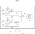
- FIG. 5 is a constitutional view of the liquid chromatograph 1 according to a second embodiment.
- the configuration from the eluent bottle 11 to the separation column 15 described in the first embodiment is duplicated and is connected to the mass spectrometer as the detector 16 via a switching valve 18.
- the control unit 17 controls the entire configuration.
- Other configurations are the same as the first embodiment.
- the sample from the autosampler (not illustrated) can be introduced to any one of the two sample filling units 14, and the sample filling unit 14 of the introduction destination is selected by the instruction from the control unit 17.
- the configuration from the eluent bottle 11 to the separation column 15 described in the first embodiment is duplicated.
- the configuration from the eluent bottle 11 to the separation column 15 may be further duplicated and connected to the mass spectrometer as the detector 16 via the switching valve 18.
- the detector 16 may be arranged in parallel and, for example, two detectors 16 may be connected in parallel to the downstream of the switching valve 18.
- FIG. 6 is a flow chart of determining a propriety of measurement by using the analysis flow channel 20 according to the second embodiment.
- the control unit 17 When a measurement instruction is received, and processing start S201 is performed, the control unit 17 performs measurement condition acquisition S202.
- the measurement conditions include the type of sample, the type of eluent, the gradient liquid feeding condition, the type of separation column 15, and the like.
- the control unit 17 Based on the sample identification information and the analysis item information received from another control device (not illustrated), the control unit 17 reads measurement items corresponding to the sample identification information and the analysis item information from the data table stored in the control unit 17.
- the control unit 17 performs acquisition S203 of an upper limit of pressure P1 limit .
- the upper limit of pressure P1 limit is an upper limit of pressure that is determined by members configuring the first analysis flow channel 20, particularly the first separation column 15 and is permissible during liquid feeding.
- the control unit 17 reads the upper limit value of pressure corresponding to the first separation column 15 (currently connected to the first analysis flow channel 20) used for measurement from the data table described above and sets the upper limit value as the upper limit of pressure P1 limit .
- the control unit 17 instructs the pump 12 of the first analysis flow channel 20 to perform liquid feeding start S204.
- the control unit 17 acquires pressure of the first analysis flow channel 20 from the pressure sensor 13 of the first analysis flow channel 20 to perform acquisition S205 of initial pressure P1 ini at the time of liquid feeding start.
- the control unit 17 performs calculation S206 of maximum pressure presumed P1 max .
- the calculation can be performed by a known pressure calculation method by using elements of the above-described known parameter such as the initial pressure P1 ini , a diameter and a length of the first analysis flow channel 20, and a viscosity of the mobile phase.
- elements that are likely to change in each measurement are the gradient liquid feeding condition in the measurement condition and the initial pressure P1 ini . Therefore, if the gradient liquid feeding condition and the initial pressure P1 ini are acquired as the parameters, other elements can be calculated as predetermined constants.
- the control unit 17 performs comparison S207 between the maximum pressure presumed P1 max and the upper limit of pressure P1 limit . If the maximum pressure presumed P1 max is less than the upper limit of pressure P1 limit , measurement execution S208 is performed by using the first analysis flow channel 20. If the maximum pressure presumed P1 max is the upper limit of pressure P1 limit and more, checking S211 of the other analysis flow channel 20 is performed.
- the control unit 17 performs measurement execution S208 using the first analysis flow channel 20. That is, it is determined that the measurement using the first analysis flow channel 20 can be performed, and sample filling by the sample filling unit 14 of the first analysis flow channel 20 is performed. Thereafter, the sample is separated in the first separation column 15, and is detected by the mass spectrometer connected to the first analysis flow channel 20 by the switching valve 18.
- the control unit 17 performs determination S209 whether there is next measurement. If there is the next measurement, measurement condition acquisition S202 of the next measurement is performed. If there is no next measurement, processing end S210 is performed.
- the control unit 17 performs checking S211 of the other analysis flow channel 20.
- the checking is to check whether the other analysis flow channel 20 (the second analysis flow channel 20) can be used. For example, if the sample is not separated by the second analysis flow channel 20, the remaining amounts of the eluents of the eluent bottle 11 connected to the second analysis flow channel 20 are sufficient, and the usage preparation (equilibration and heating) of the separation column 15 (the second separation column 15) of the second analysis flow channel 20 is completed, it is determined that the second analysis flow channel 20 can be used.
- Processing contents from measurement condition acquisition S212 to calculation S216 of the maximum pressure presumed P1 max in the other analysis flow channel 20 are the same as processing contents from measurement condition acquisition S202 to calculation S206 of the maximum pressure presumed P1 max in the first analysis flow channel 20, except that the target is the second analysis flow channel 20 instead of the first analysis flow channel 20.
- the control unit 17 After the calculation S216 of the maximum pressure presumed P1 max in the second analysis flow channel 20 is performed, the control unit 17 performs comparison S217 between the maximum pressure presumed P1 max and the upper limit of pressure P1 limit in the second analysis flow channel 20. When the maximum pressure presumed P1 max is less than the upper limit of pressure P1 limit , the control unit 17 performs measurement execution S218 using the second analysis flow channel 20. If the maximum pressure presumed P1 max is the upper limit of pressure P1 limit and more, processing end S210 is performed.
- the control unit 17 performs measurement execution S208 by using the second analysis flow channel 20. That is, it is determined that measurement using the second analysis flow channel 20 can be performed, and the sample filling by the sample filling unit 14 of the second analysis flow channel 20 is performed. Thereafter, the sample is separated by the second separation column 15 and detected by the mass spectrometer as the detector 16 connected to the second analysis flow channel 20 by the switching valve 18.
- the control unit 17 performs determination S219 whether there is next measurement. If there is the next measurement, measurement condition acquisition S212 of the next measurement is performed. If there is no next measurement, processing end S210 is performed.
- Acquisition S213 of the upper limit of pressure and subsequent processing after measurement condition acquisition S212 of the next measurement is performed are performed by the second analysis flow channel 20. This is because, it is estimated that the deterioration of the first separation column 15 progresses in the first analysis flow channel 20, and the pressure is in the state of the pressure change 502C when the separation column 15 illustrated in FIG. 4 is further deteriorated. If parameters of the first analysis flow channel 20 are changed in a case where the first separation column 15 is replaced or the like, the determination of a propriety of measurement using the analysis flow channel 20 illustrated in FIG. 6 may start from S201.
- the sample filling can be performed by the other analysis flow channel 20.
- the technique of the invention can be applied to the other eluents.
- the mixed eluents are not limited to two types and may be three types and more.
- the configuration in which the eluent bottle 11 and the pump 12 are paired is exemplified, but the configuration in which the number of the pumps 12 is less than the number of the eluent bottles 11 and the eluent bottle 11 connected to the pump 12 is switched by the switching valve may be used.
- each parameter is stored by the control unit 17, but the parameters may be acquired by direct measurement during manufacture of the liquid chromatograph 1, startup, analysis operation, maintenance, or the like and may be acquired from an external server via the network.
- the control unit 17 does not have to store all elements exemplified as items of each parameter, and the control unit 17 may be able to acquire elements required for estimating liquid feeding pressure.
- control unit 17 can be configured by hardware such as a circuit device implementing the function or configured by an arithmetic device executing software implementing the function. A form in which the single control unit 17 controls each part described in the embodiments is described, but the individual control unit 17 may be provided for each unit.
- the control unit 17 may be incorporated in the liquid chromatograph 1 or may be an external controller.
- the control unit 17 monitors the pressure of the analysis flow channel 20 detected by the pressure sensor 13, determines a propriety of measurement using the analysis flow channel 20, that is, changes the operation of the sample filling unit 14 when the predetermined condition is satisfied.
- an alert may be issued instead.
- the alert may have any form. For example, it is conceivable to display an alert image on a screen (not illustrated) connected to the control unit 17, to operate an alarm device, and to output data describing the content of the alert.
- data is read from data table stored by the control unit 17, but the user may input the data to the control unit 17 by via an input unit (not illustrated), or the control unit 17 may acquire the data from other control device via communication.
- the invention is not limited to the above-described embodiments and includes various modifications.
- the above-described embodiments are described in detail to explain the invention in an easy-to-understand manner and are not necessarily limited to those having all the described configurations. It is possible to replace a part of the configuration of one embodiment with the configuration of another embodiment, and it is also possible to add the configuration of another embodiment to the configuration of one embodiment. It is possible to add, delete, or replace a part of the configuration of each embodiment with another configuration.
Landscapes
- Chemical & Material Sciences (AREA)
- Analytical Chemistry (AREA)
- General Health & Medical Sciences (AREA)
- Life Sciences & Earth Sciences (AREA)
- Health & Medical Sciences (AREA)
- Biochemistry (AREA)
- Physics & Mathematics (AREA)
- General Physics & Mathematics (AREA)
- Immunology (AREA)
- Pathology (AREA)
- Chemical Kinetics & Catalysis (AREA)
- Treatment Of Liquids With Adsorbents In General (AREA)
- Other Investigation Or Analysis Of Materials By Electrical Means (AREA)
Applications Claiming Priority (2)
| Application Number | Priority Date | Filing Date | Title |
|---|---|---|---|
| JP2020215049 | 2020-12-24 | ||
| PCT/JP2021/044920 WO2022138136A1 (ja) | 2020-12-24 | 2021-12-07 | 液体クロマトグラフの制御方法および液体クロマトグラフ |
Publications (1)
| Publication Number | Publication Date |
|---|---|
| EP4270000A1 true EP4270000A1 (en) | 2023-11-01 |
Family
ID=82159667
Family Applications (1)
| Application Number | Title | Priority Date | Filing Date |
|---|---|---|---|
| EP21910285.2A Pending EP4270000A1 (en) | 2020-12-24 | 2021-12-07 | Liquid chromatograph control method and liquid chromatograph |
Country Status (5)
| Country | Link |
|---|---|
| US (1) | US20240019407A1 (ja) |
| EP (1) | EP4270000A1 (ja) |
| JP (1) | JPWO2022138136A1 (ja) |
| CN (1) | CN116569035A (ja) |
| WO (1) | WO2022138136A1 (ja) |
Family Cites Families (4)
| Publication number | Priority date | Publication date | Assignee | Title |
|---|---|---|---|---|
| US4422942A (en) * | 1981-09-09 | 1983-12-27 | Isco, Inc. | Method for liquid chromatography |
| JPH07103151B2 (ja) * | 1990-06-28 | 1995-11-08 | 日本碍子株式会社 | アフィニティクロマトグラフィーによる抗体の精製方法 |
| CN110998312A (zh) * | 2017-06-19 | 2020-04-10 | 沃特世科技公司 | 用于确定科学器械系统中的平衡和稳定性的技术 |
| JP6964065B2 (ja) * | 2018-12-10 | 2021-11-10 | 株式会社日立ハイテク | 液体クロマトグラフ質量分析装置 |
-
2021
- 2021-12-07 CN CN202180080249.6A patent/CN116569035A/zh active Pending
- 2021-12-07 JP JP2022572089A patent/JPWO2022138136A1/ja active Pending
- 2021-12-07 US US18/036,950 patent/US20240019407A1/en active Pending
- 2021-12-07 EP EP21910285.2A patent/EP4270000A1/en active Pending
- 2021-12-07 WO PCT/JP2021/044920 patent/WO2022138136A1/ja active Application Filing
Also Published As
| Publication number | Publication date |
|---|---|
| US20240019407A1 (en) | 2024-01-18 |
| JPWO2022138136A1 (ja) | 2022-06-30 |
| WO2022138136A1 (ja) | 2022-06-30 |
| CN116569035A (zh) | 2023-08-08 |
Similar Documents
| Publication | Publication Date | Title |
|---|---|---|
| US7578173B2 (en) | Chromatography system with flow sensing | |
| US7722764B2 (en) | Gradient pump apparatus | |
| EP3896440A1 (en) | Liquid chromatograph mass spectrometer | |
| EP3933399A1 (en) | Liquid chromatographic analyzer and control method thereof | |
| US10429360B2 (en) | Liquid chromatograph control system and liquid chromatograph control method | |
| US20180078875A1 (en) | Method and an apparatus for controlling fluid flowing through a chromatographic system | |
| CN107407663B (zh) | 因样品分离设备中流体容纳体积的不同特性所产生的假象补偿 | |
| US9651526B2 (en) | Liquid chromatograph | |
| JP2012145382A (ja) | 液体クロマトグラフ分析装置 | |
| EP4270000A1 (en) | Liquid chromatograph control method and liquid chromatograph | |
| JP7282801B2 (ja) | 複数の液体クロマトグラフを有する分析装置およびその分析方法 | |
| US10281439B2 (en) | Method of transmitting control data for system conversion among liquid chromatographs | |
| EP3367091A1 (en) | Gas chromatograph | |
| WO2019073442A1 (en) | MATCHING RESTRICTORS AND SEPARATION COLUMNS | |
| EP3508846A1 (en) | Control device for liquid chromatography analyzer, control method for liquid chromatography analyzer, and liquid chromatography analysis system | |
| US20190113488A1 (en) | System and method for diagnosing a condition of a restrictor | |
| JP2011179962A (ja) | 高速液体クロマトグラフ装置及び高速液体クロマトグラフ装置の液体送液方法 | |
| JP7262472B2 (ja) | 液体クロマトグラフを有する分析装置および液体クロマトグラフの分析方法 | |
| CN115398225B (zh) | 液相层析分析系统 | |
| CN113167772A (zh) | 具有多个色谱仪的分析装置及其控制方法 | |
| CN113325123A (zh) | 气相色谱仪 | |
| JP2021110548A (ja) | 分析装置及び分析装置の使用方法 | |
| JP2005351717A (ja) | グラジエント送液システム | |
| JP2011033556A (ja) | 液体クロマトグラフ装置 | |
| CN117136301A (zh) | 具有hplc的自动分析装置以及该自动分析装置的控制方法 |
Legal Events
| Date | Code | Title | Description |
|---|---|---|---|
| STAA | Information on the status of an ep patent application or granted ep patent |
Free format text: STATUS: THE INTERNATIONAL PUBLICATION HAS BEEN MADE |
|
| PUAI | Public reference made under article 153(3) epc to a published international application that has entered the european phase |
Free format text: ORIGINAL CODE: 0009012 |
|
| STAA | Information on the status of an ep patent application or granted ep patent |
Free format text: STATUS: REQUEST FOR EXAMINATION WAS MADE |
|
| 17P | Request for examination filed |
Effective date: 20230524 |
|
| AK | Designated contracting states |
Kind code of ref document: A1 Designated state(s): AL AT BE BG CH CY CZ DE DK EE ES FI FR GB GR HR HU IE IS IT LI LT LU LV MC MK MT NL NO PL PT RO RS SE SI SK SM TR |
|
| DAV | Request for validation of the european patent (deleted) | ||
| DAX | Request for extension of the european patent (deleted) |