EP4269934B1 - Hohlladungssprengkopf und verfahren zur herstellung eines solchen sprengkopfs - Google Patents
Hohlladungssprengkopf und verfahren zur herstellung eines solchen sprengkopfs Download PDFInfo
- Publication number
- EP4269934B1 EP4269934B1 EP23168501.7A EP23168501A EP4269934B1 EP 4269934 B1 EP4269934 B1 EP 4269934B1 EP 23168501 A EP23168501 A EP 23168501A EP 4269934 B1 EP4269934 B1 EP 4269934B1
- Authority
- EP
- European Patent Office
- Prior art keywords
- liner
- warhead
- shaped charge
- conical
- casing
- Prior art date
- Legal status (The legal status is an assumption and is not a legal conclusion. Google has not performed a legal analysis and makes no representation as to the accuracy of the status listed.)
- Active
Links
Images
Classifications
-
- F—MECHANICAL ENGINEERING; LIGHTING; HEATING; WEAPONS; BLASTING
- F42—AMMUNITION; BLASTING
- F42B—EXPLOSIVE CHARGES, e.g. FOR BLASTING, FIREWORKS, AMMUNITION
- F42B1/00—Explosive charges characterised by form or shape but not dependent on shape of container
- F42B1/02—Shaped or hollow charges
- F42B1/036—Manufacturing processes therefor
-
- F—MECHANICAL ENGINEERING; LIGHTING; HEATING; WEAPONS; BLASTING
- F42—AMMUNITION; BLASTING
- F42B—EXPLOSIVE CHARGES, e.g. FOR BLASTING, FIREWORKS, AMMUNITION
- F42B33/00—Manufacture of ammunition; Dismantling of ammunition; Apparatus therefor
- F42B33/02—Filling cartridges, missiles, or fuzes; Inserting propellant or explosive charges
- F42B33/0214—Filling cartridges, missiles, or fuzes; Inserting propellant or explosive charges by casting
-
- F—MECHANICAL ENGINEERING; LIGHTING; HEATING; WEAPONS; BLASTING
- F42—AMMUNITION; BLASTING
- F42B—EXPLOSIVE CHARGES, e.g. FOR BLASTING, FIREWORKS, AMMUNITION
- F42B1/00—Explosive charges characterised by form or shape but not dependent on shape of container
- F42B1/02—Shaped or hollow charges
- F42B1/028—Shaped or hollow charges characterised by the form of the liner
-
- F—MECHANICAL ENGINEERING; LIGHTING; HEATING; WEAPONS; BLASTING
- F42—AMMUNITION; BLASTING
- F42B—EXPLOSIVE CHARGES, e.g. FOR BLASTING, FIREWORKS, AMMUNITION
- F42B1/00—Explosive charges characterised by form or shape but not dependent on shape of container
- F42B1/02—Shaped or hollow charges
- F42B1/032—Shaped or hollow charges characterised by the material of the liner
-
- F—MECHANICAL ENGINEERING; LIGHTING; HEATING; WEAPONS; BLASTING
- F42—AMMUNITION; BLASTING
- F42B—EXPLOSIVE CHARGES, e.g. FOR BLASTING, FIREWORKS, AMMUNITION
- F42B12/00—Projectiles, missiles or mines characterised by the warhead, the intended effect, or the material
- F42B12/02—Projectiles, missiles or mines characterised by the warhead, the intended effect, or the material characterised by the warhead or the intended effect
- F42B12/04—Projectiles, missiles or mines characterised by the warhead, the intended effect, or the material characterised by the warhead or the intended effect of armour-piercing type
- F42B12/10—Projectiles, missiles or mines characterised by the warhead, the intended effect, or the material characterised by the warhead or the intended effect of armour-piercing type with shaped or hollow charge
-
- B—PERFORMING OPERATIONS; TRANSPORTING
- B33—ADDITIVE MANUFACTURING TECHNOLOGY
- B33Y—ADDITIVE MANUFACTURING, i.e. MANUFACTURING OF THREE-DIMENSIONAL [3D] OBJECTS BY ADDITIVE DEPOSITION, ADDITIVE AGGLOMERATION OR ADDITIVE LAYERING, e.g. BY 3D PRINTING, STEREOLITHOGRAPHY OR SELECTIVE LASER SINTERING
- B33Y80/00—Products made by additive manufacturing
Definitions
- This invention relates to a shaped charge warhead and a method for producing the warhead.
- the invention is applicable or may be applied in the defence, demolition or mining sector.
- a shaped charge warhead is a device comprising a fragmentation casing which defines the space inside which a shaped charge liner is positioned. The space between the liner and the casing is filled with explosives.
- a similar device is known from document WO 2020027736 A1 which discloses an explosive device configured for outputting a quasi-planar shock wave.
- the shape of the casing close to the rear region may be further shaped in a truncated cone shape for a more effective concentration of the pressure wave on the liner.
- the SCW is mounted on a standoff which establishes the optimum distance for the formation of the slug.
- the detonation of the explosive causes a pressure wave which strikes the liner causing the walls to collapse along the axis of axially symmetry of the cone.
- the high pressure causes the heating of the material, thus increasing the propensity to sliding (less resistance and greater ductility).
- the collapse of the walls of the liner concentrates the mass of the liner along the axis.
- the vertex of the cone moves in an axial direction before the portions of material on the walls which are struck by the pressure wave at successive points in time. This causes the formation of a slug of practically melted material with a difference in speed between the apex of the slug and the tail which causes the extension and, if necessary, the fragmentation over long distances.
- not all the material of the liner participates in the formation of the slug.
- the materials for the casing, the liner and the standoff are generally different and the materials for the liner are limited to certain classes of metals and alloys (mainly copper and in some cases aluminium).
- the liner is obtained by subtracting techniques and the shape is generally conical with a constant thickness or hemispherical with a constant thickness.
- the casing may have grooves machined on the inside or outside surface. These grooves are designed to control the dimensions of the fragments.
- SCW can be assembled in a configuration with two shaped charges in line to maximise penetration.
- the assembly operation is critical as misalignments between the liner and the casing can result in asymmetries in the extension of the detonation wave which are reflected in the shape and the penetrative capacity of the slug.
- the main technique for controlling the fragmentation of the casing is based on the creation of surface geometrical defects by means of machining by removal. In this way, the possible geometrical configurations of defects which can be used are greatly limited.
- the technical purpose of the invention is therefore to provide a shaped charge warhead and a method for producing the warhead which are able to overcome the drawbacks of the prior art.
- the aim of the invention is therefore to provide a shaped charge warhead and a method for producing the warhead which allow the assembly operations to be eliminated.
- a further aim of the invention is to provide a shaped charge warhead and a method for producing the warhead which allow a liner to be made with a variable thickness and to use materials which cannot be used with traditional machining techniques.
- a shaped charge warhead according to claim 1 comprising an axially
- symmetrical fragmentation casing designed to define a containment space and having in an end wall a casting hole for the explosive, a detonator housed in the casting hole and a conical or hemispherical shaped charge liner positioned inside the containment space.
- the casing and the liner are made in a single body, preferably by means of additive manufacturing.
- the casing extends along a respective axis of extension in such a way as to also define a standoff of the charge warhead.
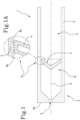
- warhead 1 denotes in its entirety a shaped charge warhead which, for simplicity of description, will hereafter be referred to as warhead 1.
- the warhead 1 comprises an axially symmetric casing 2 designed to define a containment space "V" and having in a base portion 2a a casting hole 3 for the explosive.
- the casing 2 has a cylindrical shape but other configurations can be made.
- the base portion 2a of the casing 2 has geometrical defects in the form of volumes of powders which are non-sintered and/or the presence of shaping in the thickness.
- the base portion 2a has geometrical defects and/or geometrical discontinuities in the thickness.
- the warhead 1 also comprises a detonator (not illustrated) housed in the casting hole 3.
- the warhead 1 also comprises a conical or hemispherical shaped charge liner 4 positioned inside the containment space "V".
- a conical or hemispherical shaped charge liner 4 positioned inside the containment space "V".
- the conical liner 4 has a variable thickness.
- the variable thickness of the conical liner 4 allows the distribution of the masses participating in the formation of the slug to be optimised.
- the conical liner 4 has a structure with cellular partitions.
- Each cellular partition contains non-sintered powder which contributes to the formation of the slug.
- the casing 2 and the conical liner 4 are made in a single body by means of an additive manufacturing technique. In other words, the casing 2 and the conical liner 4 are made in a single part without interruption.
- the casing 2 and the conical liner 4 are made by means of additive manufacturing by powder bed fusion.
- the casing 2 extends along a respective axis of extension "X" in such a way as to also define a standoff 5 of the warhead 1.
- the conical liner 4 is connected to the casing 2 by a continuous connection 6 made with non-sintered spaces.
- the continuous connection 6 is made by means of two connecting bodies 6a.
- the warhead 1 is made by means of powders for additive manufacturing.
- the warhead 1 is made of powders of metal alloys which include copper alloys, aluminium alloys, tungsten, bismuth or zirconium alloys.
- the warhead 1 may also be made with other types of metallic powder not described here.
- the above-mentioned warhead 1 has a high constructional simplicity.
- the particular structure of the conical liner 4 guarantees a greater effectiveness of the warhead 1.
- the warhead 1 has a greater penetrative capacity which guarantees better performance in the various fields of use of the warhead 1.
- the warhead 1 can be made from materials which could not otherwise be used.
- the invention also relates to a method for producing the shaped charge warhead 1 as described above. For this reason, the warhead 1 can be obtained with the method according to the invention.
- the method comprises a first step of making a casing 2 and a conical liner 4 defining a single body using an additive manufacturing technique.
- the ideal solution for defining the single body has been found by means of numerical simulation with structural, qualified and certified software used in the reference sector.
- the dimensions of the single body may be scaled up with the only limit of the maximum dimensions of the pressing space of the machine used.
- the casing 2 and the conical liner 4 are made by means of additive manufacturing by powder bed fusion.
- the warhead 1 is made by means of powders for additive manufacturing.
- the warhead 1 is made of powders of copper, aluminium alloys, tungsten, bismuth or zirconium alloys.
- the method also comprises introducing explosive device through the casting hole 3 of the casing 2.
- the explosive device is introduced into a space "V1" defined between the casing 2 and the conical liner 4.
- the method comprises closing the casting hole 3 (that is, said space "V1") housing a detonator in the casting hole 3.
- the method also comprises a step of performing a thermal treatment after the step of making the single body and a step of surface finishing following a removal of forging supports.
- the method comprises processing the warhead 1 to remove possible imperfections due to the additive manufacturing technique used.
- the invention is able to overcome the drawbacks of the prior art.
- the invention allows the assembly operations to be eliminated.
- the invention allows a liner to be made with variable thickness and materials to be used which cannot normally be used with traditional processing techniques.
- the invention allows, with the introduction of geometrical defects inside the thickness of the casing, the dimensions of the fragments caused by the detonation to be controlled.
- the invention is characterised by a high level of constructional simplicity and greater effectiveness of the "liner".
Landscapes
- Engineering & Computer Science (AREA)
- General Engineering & Computer Science (AREA)
- Manufacturing & Machinery (AREA)
- Chemical & Material Sciences (AREA)
- Combustion & Propulsion (AREA)
- Manufacture And Refinement Of Metals (AREA)
- Powder Metallurgy (AREA)
Claims (9)
- Hohlladungssprengkopf (1), umfassend:- ein axialsymmetrisches Gehäuse (2), das ausgestaltet ist, um einen Begrenzungsraum (V) zu definieren, und aufweisend in einem Basisabschnitt (2a) ein Gussloch (3) für einen Sprengstoff;- einen Detonator, der im Gussloch (3) untergebracht ist;- eine konische oder halbkugelförmige Hohlladungseinlage (4), die im Begrenzungsraum (V) positioniert ist,wobei das Gehäuse (2) und die konische Einlage (4) in einem Stück ausgebildet sind, wobei sich das Gehäuse (2) entlang einer jeweiligen Ausdehnungsachse (X) so erstreckt, dass es ein Distanzstück (5) des Hohlladungssprengkopfs (1) definiert,dadurch gekennzeichnet, dass die konische oder halbkugelförmige Einlage (4) eine Struktur mit Zellunterteilungen aufweist, wobei jede Zellunterteilung ungesintertes Pulver enthält.
- Hohlladungssprengkopf (1) nach Anspruch 1, wobei das zylindrische Gehäuse (2) und die konische oder halbkugelförmige Einlage (4) per additiver Fertigung gefertigt sind.
- Hohlladungssprengkopf (1) nach Anspruch 1 oder 2, wobei die konische oder halbkugelförmige Einlage (4) eine variable Dicke aufweist.
- Hohlladungssprengkopf (1) nach einem der vorhergehenden Ansprüche, wobei die konische oder halbkugelförmige Einlage (4) mit dem zylindrischen Gehäuse (2) durch eine durchgehende Verbindung (6) mit nicht gesinterten Räumen verbunden ist.
- Hohlladungssprengkopf (1) nach einem der vorhergehenden Ansprüche, wobei der Sprengkopf (1) per additiver Fertigung von Pulvern aus Kupfer, Aluminiumlegierungen, Wolfram, Bismut oder Zirkoniumlegierungen gefertigt ist.
- Hohlladungssprengkopf (1) nach einem der vorhergehenden Ansprüche, wobei ein Basisabschnitt (2a) des zylindrischen Gehäuses (2) geometrische Fehler in der Form von Volumina von Pulver aufweist, die nicht gesintert sind, und/oder geometrische Fehlstellen in der Dicke.
- Verfahren zur Herstellung eines Hohlladungssprengkopfs (1) nach einem der vorhergehenden Ansprüche, umfassend die folgenden Schritte:- Herstellen eines Gehäuses (2) und einer konischen Einlage (4), definierend einen einzelnen Körper, unter Nutzung einer Technik der additiven Fertigung;- Einführen von Sprengstoff durch das Gussloch (3) des zylindrischen Gehäuses (2) in einen Raum (V1), der zwischen dem Gehäuse (2) und der konischen Einlage (4) gebildet ist;- Verschließen des Gusslochs (3) durch die Unterbringung eines Detonators im Gussloch (3).
- Herstellungsverfahren nach Anspruch 7, wobei das zylindrische Gehäuse und die konische Einlage per additiver Fertigung durch pulverbettbasiertes Schmelzen gefertigt sind.
- Herstellungsverfahren nach Anspruch 7 oder 8, zudem umfassend einen Schritt zum Durchführen einer thermischen Behandlung nach dem Schritt zum Herstellen des einzelnen Körpers und einen Schritt zur Oberflächenbearbeitung nach einer Entfernung von Schmiedestützen.
Applications Claiming Priority (1)
| Application Number | Priority Date | Filing Date | Title |
|---|---|---|---|
| IT102022000008426A IT202200008426A1 (it) | 2022-04-28 | 2022-04-28 | Testata a carica sagomata ed un metodo di produzione della testata |
Publications (3)
| Publication Number | Publication Date |
|---|---|
| EP4269934A1 EP4269934A1 (de) | 2023-11-01 |
| EP4269934B1 true EP4269934B1 (de) | 2024-12-04 |
| EP4269934C0 EP4269934C0 (de) | 2024-12-04 |
Family
ID=82781056
Family Applications (1)
| Application Number | Title | Priority Date | Filing Date |
|---|---|---|---|
| EP23168501.7A Active EP4269934B1 (de) | 2022-04-28 | 2023-04-18 | Hohlladungssprengkopf und verfahren zur herstellung eines solchen sprengkopfs |
Country Status (3)
| Country | Link |
|---|---|
| US (1) | US12235088B2 (de) |
| EP (1) | EP4269934B1 (de) |
| IT (1) | IT202200008426A1 (de) |
Cited By (1)
| Publication number | Priority date | Publication date | Assignee | Title |
|---|---|---|---|---|
| DE102024122077A1 (de) * | 2024-06-26 | 2025-12-31 | Unmanned Sovereignty GmbH | Verfahren zur Herstellung wenigstens eines Teils einer projektilbildenden Ladung, Teil einer projektilbildenden Ladung, projektilbildende Ladung, Unbemannte Plattform |
Family Cites Families (31)
| Publication number | Priority date | Publication date | Assignee | Title |
|---|---|---|---|---|
| US2605703A (en) * | 1944-07-06 | 1952-08-05 | Du Pont | Liner for hollow charges |
| US2587243A (en) * | 1946-10-16 | 1952-02-26 | I J Mccullough | Cutting apparatus |
| US3025794A (en) * | 1957-05-15 | 1962-03-20 | Schlumberger Well Surv Corp | Perforating apparatus |
| US3104186A (en) * | 1961-03-29 | 1963-09-17 | Explosive Engineering Corp | Method of expediting the removal of frozen masses |
| US3242987A (en) * | 1962-03-06 | 1966-03-29 | Schlumberger Well Surv Corp | Methods and apparatus for completing wells |
| US4222329A (en) * | 1973-07-16 | 1980-09-16 | The United States Of America As Represented By The Secretary Of The Navy | Underwater cutting device |
| US4109576A (en) * | 1975-06-18 | 1978-08-29 | Eckels Robert E | Shaped charge with enhanced penetration |
| GB1520250A (en) * | 1976-01-27 | 1978-08-02 | Ici Ltd | Method of cutting metal elements under water and a shaped explosive charce device therefor |
| DE3628622C1 (de) * | 1986-08-22 | 1996-08-08 | Fraunhofer Ges Forschung | Vorrichtung zur Erzeugung sprenggeformter Projektile |
| US9476682B1 (en) * | 1989-01-26 | 2016-10-25 | Qinetiq Limited | Multi-charge munitions, incorporating hole-boring charge assemblies |
| US6494139B1 (en) * | 1990-01-09 | 2002-12-17 | Qinetiq Limited | Hole boring charge assembly |
| ZA932083B (en) * | 1992-05-04 | 1993-10-15 | Jet Tech Pty Ltd | A shaped explosive charge, a method of blasting using the shaped explosive charge and a kit to make it |
| US5522319A (en) * | 1994-07-05 | 1996-06-04 | The United States Of America As Represented By The United States Department Of Energy | Free form hemispherical shaped charge |
| US5859383A (en) * | 1996-09-18 | 1999-01-12 | Davison; David K. | Electrically activated, metal-fueled explosive device |
| DE29713229U1 (de) * | 1997-07-25 | 1998-12-03 | Diehl Stiftung & Co., 90478 Nürnberg | Gefechtskopf |
| ATE357642T1 (de) * | 1999-10-01 | 2007-04-15 | Kevin Mark Powell | Verfahren zur sprengung von schnee- oder eis- formationen, insbesondere für lawinenbeherrschung |
| US6606950B1 (en) * | 2001-07-24 | 2003-08-19 | Charles Ray Putman | Method and apparatus for positioning a shaped charge |
| AU2002952984A0 (en) * | 2002-11-28 | 2002-12-12 | Scott Allman | Forced entry system |
| SE526920C2 (sv) * | 2003-06-04 | 2005-11-15 | Bofors Defence Ab | Anordning vid sprängsats med åtminstone två inlägg/liners |
| US20050115448A1 (en) * | 2003-10-22 | 2005-06-02 | Owen Oil Tools Lp | Apparatus and method for penetrating oilbearing sandy formations, reducing skin damage and reducing hydrocarbon viscosity |
| US8037829B1 (en) * | 2008-06-11 | 2011-10-18 | Raytheon Company | Reactive shaped charge, reactive liner, and method for target penetration using a reactive shaped charge |
| US20100043661A1 (en) * | 2008-08-25 | 2010-02-25 | Ensign-Bickford Aerospace & Defense Company | Explosive cutting charge |
| US8616130B2 (en) * | 2011-01-19 | 2013-12-31 | Raytheon Company | Liners for warheads and warheads having improved liners |
| US20140291022A1 (en) * | 2013-03-29 | 2014-10-02 | Schlumberger Technology Corporation | Amorphous shaped charge component and manufacture |
| US9360222B1 (en) * | 2015-05-28 | 2016-06-07 | Innovative Defense, Llc | Axilinear shaped charge |
| US10731955B2 (en) * | 2017-04-13 | 2020-08-04 | Lawrence Livermore National Security, Llc | Modular gradient-free shaped charge |
| US10520286B2 (en) * | 2018-04-06 | 2019-12-31 | Dynaenergetics Gmbh & Co. Kg | Inlay for shaped charge and method of use |
| CA3108299A1 (en) * | 2018-07-31 | 2020-02-06 | Orica International Pte Ltd | Explosive device configured for producing a quasi-planar shock wave |
| US20200378736A1 (en) * | 2019-03-25 | 2020-12-03 | Suprameca Sas | Wall Breaching Charge |
| US12253339B2 (en) * | 2021-10-25 | 2025-03-18 | DynaEnergetics Europe GmbH | Adapter and shaped charge apparatus for optimized perforation jet |
| US11965719B2 (en) * | 2022-05-10 | 2024-04-23 | Halliburton Energy Services, Inc. | Segment pressing of shaped charge powder metal liners |
-
2022
- 2022-04-28 IT IT102022000008426A patent/IT202200008426A1/it unknown
-
2023
- 2023-04-18 EP EP23168501.7A patent/EP4269934B1/de active Active
- 2023-04-26 US US18/307,307 patent/US12235088B2/en active Active
Cited By (1)
| Publication number | Priority date | Publication date | Assignee | Title |
|---|---|---|---|---|
| DE102024122077A1 (de) * | 2024-06-26 | 2025-12-31 | Unmanned Sovereignty GmbH | Verfahren zur Herstellung wenigstens eines Teils einer projektilbildenden Ladung, Teil einer projektilbildenden Ladung, projektilbildende Ladung, Unbemannte Plattform |
Also Published As
| Publication number | Publication date |
|---|---|
| EP4269934A1 (de) | 2023-11-01 |
| US20240200921A1 (en) | 2024-06-20 |
| EP4269934C0 (de) | 2024-12-04 |
| IT202200008426A1 (it) | 2023-10-28 |
| US12235088B2 (en) | 2025-02-25 |
Similar Documents
| Publication | Publication Date | Title |
|---|---|---|
| US7093542B2 (en) | Warhead with integral, direct-manufactured features | |
| US3100445A (en) | Shaped charge and method of firing the same | |
| EP1299687B1 (de) | Bleifreie einlagezusammensetzung für hohlladungen | |
| US9175936B1 (en) | Swept conical-like profile axisymmetric circular linear shaped charge | |
| US7011027B2 (en) | Coated metal particles to enhance oil field shaped charge performance | |
| US8813651B1 (en) | Method of making shaped charges and explosively formed projectiles | |
| US4664035A (en) | Missile warheads | |
| EP3387365B1 (de) | Durch generative fertigung hergestellte auskleidung mehrerer explosiv geformter geschosse | |
| US5279228A (en) | Shaped charge perforator | |
| CA2182409A1 (en) | Cascade shaped charge | |
| US3136249A (en) | Shaped charge explosive unit and liner therefor | |
| US6026750A (en) | Shaped charge liner with integral initiation mechanism | |
| US7779760B2 (en) | Shaped charge assembly and method of damaging a target | |
| EP4269934A1 (de) | Hohlladungssprengkopf und verfahren zur herstellung eines solchen sprengkopfs | |
| US5847312A (en) | Shaped charge devices with multiple confinements | |
| US6308634B1 (en) | Precursor-follow through explosively formed penetrator assembly | |
| RU2171445C1 (ru) | Способ изготовления оболочки осколочного боеприпаса | |
| EP4111128B1 (de) | Gefechtskopf | |
| US6983698B1 (en) | Shaped charge explosive device and method of making same | |
| EP1590620B1 (de) | Explosivgeformte doppelringe (defr) erzeugender gefechtskopf | |
| US8387539B1 (en) | Sculpted reactive liner with semi-cylindrical linear open cells | |
| KR102203134B1 (ko) | 연성 외장에 의해 둘러싸인 코어를 포함하는 관통자 및 그 관통자의 제조방법 | |
| Смірнова et al. | EFFECT OF MATERIAL TYPE AND LINER SHAPE ON PROPERTIES OF SHAPED CHARGES | |
| RU2668580C1 (ru) | Бронебойный оперенный подкалиберный снаряд | |
| RU2453807C2 (ru) | Боевая часть осколочного боеприпаса и способ ее изготовления |
Legal Events
| Date | Code | Title | Description |
|---|---|---|---|
| PUAI | Public reference made under article 153(3) epc to a published international application that has entered the european phase |
Free format text: ORIGINAL CODE: 0009012 |
|
| STAA | Information on the status of an ep patent application or granted ep patent |
Free format text: STATUS: THE APPLICATION HAS BEEN PUBLISHED |
|
| AK | Designated contracting states |
Kind code of ref document: A1 Designated state(s): AL AT BE BG CH CY CZ DE DK EE ES FI FR GB GR HR HU IE IS IT LI LT LU LV MC ME MK MT NL NO PL PT RO RS SE SI SK SM TR |
|
| STAA | Information on the status of an ep patent application or granted ep patent |
Free format text: STATUS: REQUEST FOR EXAMINATION WAS MADE |
|
| 17P | Request for examination filed |
Effective date: 20240429 |
|
| RBV | Designated contracting states (corrected) |
Designated state(s): AL AT BE BG CH CY CZ DE DK EE ES FI FR GB GR HR HU IE IS IT LI LT LU LV MC ME MK MT NL NO PL PT RO RS SE SI SK SM TR |
|
| GRAP | Despatch of communication of intention to grant a patent |
Free format text: ORIGINAL CODE: EPIDOSNIGR1 |
|
| STAA | Information on the status of an ep patent application or granted ep patent |
Free format text: STATUS: GRANT OF PATENT IS INTENDED |
|
| INTG | Intention to grant announced |
Effective date: 20240717 |
|
| GRAS | Grant fee paid |
Free format text: ORIGINAL CODE: EPIDOSNIGR3 |
|
| GRAA | (expected) grant |
Free format text: ORIGINAL CODE: 0009210 |
|
| STAA | Information on the status of an ep patent application or granted ep patent |
Free format text: STATUS: THE PATENT HAS BEEN GRANTED |
|
| AK | Designated contracting states |
Kind code of ref document: B1 Designated state(s): AL AT BE BG CH CY CZ DE DK EE ES FI FR GB GR HR HU IE IS IT LI LT LU LV MC ME MK MT NL NO PL PT RO RS SE SI SK SM TR |
|
| REG | Reference to a national code |
Ref country code: CH Ref legal event code: EP |
|
| REG | Reference to a national code |
Ref country code: DE Ref legal event code: R096 Ref document number: 602023001230 Country of ref document: DE |
|
| REG | Reference to a national code |
Ref country code: IE Ref legal event code: FG4D |
|
| U01 | Request for unitary effect filed |
Effective date: 20241216 |
|
| U07 | Unitary effect registered |
Designated state(s): AT BE BG DE DK EE FI FR IT LT LU LV MT NL PT RO SE SI Effective date: 20250109 |
|
| PG25 | Lapsed in a contracting state [announced via postgrant information from national office to epo] |
Ref country code: HR Free format text: LAPSE BECAUSE OF FAILURE TO SUBMIT A TRANSLATION OF THE DESCRIPTION OR TO PAY THE FEE WITHIN THE PRESCRIBED TIME-LIMIT Effective date: 20241204 |
|
| PG25 | Lapsed in a contracting state [announced via postgrant information from national office to epo] |
Ref country code: ES Free format text: LAPSE BECAUSE OF FAILURE TO SUBMIT A TRANSLATION OF THE DESCRIPTION OR TO PAY THE FEE WITHIN THE PRESCRIBED TIME-LIMIT Effective date: 20241204 |
|
| PG25 | Lapsed in a contracting state [announced via postgrant information from national office to epo] |
Ref country code: NO Free format text: LAPSE BECAUSE OF FAILURE TO SUBMIT A TRANSLATION OF THE DESCRIPTION OR TO PAY THE FEE WITHIN THE PRESCRIBED TIME-LIMIT Effective date: 20250304 |
|
| PG25 | Lapsed in a contracting state [announced via postgrant information from national office to epo] |
Ref country code: GR Free format text: LAPSE BECAUSE OF FAILURE TO SUBMIT A TRANSLATION OF THE DESCRIPTION OR TO PAY THE FEE WITHIN THE PRESCRIBED TIME-LIMIT Effective date: 20250305 |
|
| PG25 | Lapsed in a contracting state [announced via postgrant information from national office to epo] |
Ref country code: RS Free format text: LAPSE BECAUSE OF FAILURE TO SUBMIT A TRANSLATION OF THE DESCRIPTION OR TO PAY THE FEE WITHIN THE PRESCRIBED TIME-LIMIT Effective date: 20250304 |
|
| U20 | Renewal fee for the european patent with unitary effect paid |
Year of fee payment: 3 Effective date: 20250429 |
|
| PG25 | Lapsed in a contracting state [announced via postgrant information from national office to epo] |
Ref country code: SM Free format text: LAPSE BECAUSE OF FAILURE TO SUBMIT A TRANSLATION OF THE DESCRIPTION OR TO PAY THE FEE WITHIN THE PRESCRIBED TIME-LIMIT Effective date: 20241204 |
|
| PG25 | Lapsed in a contracting state [announced via postgrant information from national office to epo] |
Ref country code: PL Free format text: LAPSE BECAUSE OF FAILURE TO SUBMIT A TRANSLATION OF THE DESCRIPTION OR TO PAY THE FEE WITHIN THE PRESCRIBED TIME-LIMIT Effective date: 20241204 |
|
| PG25 | Lapsed in a contracting state [announced via postgrant information from national office to epo] |
Ref country code: IS Free format text: LAPSE BECAUSE OF FAILURE TO SUBMIT A TRANSLATION OF THE DESCRIPTION OR TO PAY THE FEE WITHIN THE PRESCRIBED TIME-LIMIT Effective date: 20250404 |
|
| PG25 | Lapsed in a contracting state [announced via postgrant information from national office to epo] |
Ref country code: SK Free format text: LAPSE BECAUSE OF FAILURE TO SUBMIT A TRANSLATION OF THE DESCRIPTION OR TO PAY THE FEE WITHIN THE PRESCRIBED TIME-LIMIT Effective date: 20241204 |
|
| PG25 | Lapsed in a contracting state [announced via postgrant information from national office to epo] |
Ref country code: CZ Free format text: LAPSE BECAUSE OF FAILURE TO SUBMIT A TRANSLATION OF THE DESCRIPTION OR TO PAY THE FEE WITHIN THE PRESCRIBED TIME-LIMIT Effective date: 20241204 |
|
| PLBE | No opposition filed within time limit |
Free format text: ORIGINAL CODE: 0009261 |
|
| STAA | Information on the status of an ep patent application or granted ep patent |
Free format text: STATUS: NO OPPOSITION FILED WITHIN TIME LIMIT |
|
| PGFP | Annual fee paid to national office [announced via postgrant information from national office to epo] |
Ref country code: IE Payment date: 20250709 Year of fee payment: 3 |
|
| 26N | No opposition filed |
Effective date: 20250905 |
|
| PG25 | Lapsed in a contracting state [announced via postgrant information from national office to epo] |
Ref country code: MC Free format text: LAPSE BECAUSE OF FAILURE TO SUBMIT A TRANSLATION OF THE DESCRIPTION OR TO PAY THE FEE WITHIN THE PRESCRIBED TIME-LIMIT Effective date: 20241204 |