EP4269784A2 - Zündsystem für brennkraftmaschine - Google Patents
Zündsystem für brennkraftmaschine Download PDFInfo
- Publication number
- EP4269784A2 EP4269784A2 EP23168775.7A EP23168775A EP4269784A2 EP 4269784 A2 EP4269784 A2 EP 4269784A2 EP 23168775 A EP23168775 A EP 23168775A EP 4269784 A2 EP4269784 A2 EP 4269784A2
- Authority
- EP
- European Patent Office
- Prior art keywords
- exciter
- controller
- driver
- multifunction controller
- multifunction
- Prior art date
- Legal status (The legal status is an assumption and is not a legal conclusion. Google has not performed a legal analysis and makes no representation as to the accuracy of the status listed.)
- Granted
Links
Images


Classifications
-
- F—MECHANICAL ENGINEERING; LIGHTING; HEATING; WEAPONS; BLASTING
- F02—COMBUSTION ENGINES; HOT-GAS OR COMBUSTION-PRODUCT ENGINE PLANTS
- F02P—IGNITION, OTHER THAN COMPRESSION IGNITION, FOR INTERNAL-COMBUSTION ENGINES; TESTING OF IGNITION TIMING IN COMPRESSION-IGNITION ENGINES
- F02P3/00—Other installations
- F02P3/06—Other installations having capacitive energy storage
- F02P3/08—Layout of circuits
- F02P3/09—Layout of circuits for control of the charging current in the capacitor
- F02P3/093—Closing the discharge circuit of the storage capacitor with semiconductor devices
- F02P3/096—Closing the discharge circuit of the storage capacitor with semiconductor devices using digital techniques
-
- F—MECHANICAL ENGINEERING; LIGHTING; HEATING; WEAPONS; BLASTING
- F02—COMBUSTION ENGINES; HOT-GAS OR COMBUSTION-PRODUCT ENGINE PLANTS
- F02P—IGNITION, OTHER THAN COMPRESSION IGNITION, FOR INTERNAL-COMBUSTION ENGINES; TESTING OF IGNITION TIMING IN COMPRESSION-IGNITION ENGINES
- F02P15/00—Electric spark ignition having characteristics not provided for in, or of interest apart from, groups F02P1/00 - F02P13/00 and combined with layout of ignition circuits
- F02P15/001—Ignition installations adapted to specific engine types
- F02P15/003—Layout of ignition circuits for gas turbine plants
-
- F—MECHANICAL ENGINEERING; LIGHTING; HEATING; WEAPONS; BLASTING
- F02—COMBUSTION ENGINES; HOT-GAS OR COMBUSTION-PRODUCT ENGINE PLANTS
- F02C—GAS-TURBINE PLANTS; AIR INTAKES FOR JET-PROPULSION PLANTS; CONTROLLING FUEL SUPPLY IN AIR-BREATHING JET-PROPULSION PLANTS
- F02C7/00—Features, components parts, details or accessories, not provided for in, or of interest apart form groups F02C1/00 - F02C6/00; Air intakes for jet-propulsion plants
- F02C7/26—Starting; Ignition
- F02C7/264—Ignition
- F02C7/266—Electric
-
- F—MECHANICAL ENGINEERING; LIGHTING; HEATING; WEAPONS; BLASTING
- F02—COMBUSTION ENGINES; HOT-GAS OR COMBUSTION-PRODUCT ENGINE PLANTS
- F02P—IGNITION, OTHER THAN COMPRESSION IGNITION, FOR INTERNAL-COMBUSTION ENGINES; TESTING OF IGNITION TIMING IN COMPRESSION-IGNITION ENGINES
- F02P11/00—Safety means for electric spark ignition, not otherwise provided for
- F02P11/02—Preventing damage to engines or engine-driven gearing
-
- F—MECHANICAL ENGINEERING; LIGHTING; HEATING; WEAPONS; BLASTING
- F02—COMBUSTION ENGINES; HOT-GAS OR COMBUSTION-PRODUCT ENGINE PLANTS
- F02P—IGNITION, OTHER THAN COMPRESSION IGNITION, FOR INTERNAL-COMBUSTION ENGINES; TESTING OF IGNITION TIMING IN COMPRESSION-IGNITION ENGINES
- F02P17/00—Testing of ignition installations, e.g. in combination with adjusting; Testing of ignition timing in compression-ignition engines
- F02P17/12—Testing characteristics of the spark, ignition voltage or current
-
- F—MECHANICAL ENGINEERING; LIGHTING; HEATING; WEAPONS; BLASTING
- F02—COMBUSTION ENGINES; HOT-GAS OR COMBUSTION-PRODUCT ENGINE PLANTS
- F02P—IGNITION, OTHER THAN COMPRESSION IGNITION, FOR INTERNAL-COMBUSTION ENGINES; TESTING OF IGNITION TIMING IN COMPRESSION-IGNITION ENGINES
- F02P11/00—Safety means for electric spark ignition, not otherwise provided for
- F02P11/06—Indicating unsafe conditions
Definitions
- This disclosure relates to engine ignition systems.
- Gas turbine engines require an ignition source to start the combustion process and relight the combustor should the flame go out during operation.
- the scheme typically is one where a high energy spark is produced that ignites the fuel source. Once commanded to produce sparks, the sparks typically continue at a prescribed rate until a command to stop is issued.
- a controller In modern architectures there is typically a controller, a power supply, an exciter unit, high tension leads, and igniter plugs.
- the controller commands the exciter to deliver energy to the igniters and monitors system health.
- the power supply provides low voltage AC or DC to powers the exciter.
- the exciter is the ignition power supply and driver that converts the low voltage power supply input to a much higher internal voltage, and applies the high voltage to charge an energy storage device.
- the exciter discharges the energy storage device stored energy to the output. Traditionally, the maximum possible charge rate defines the max spark rate.
- An engine ignition system can include a multifunction controller, and an exciter operatively connected to the multifunction controller.
- the multifunction controller can be configured to control the exciter to output an ignition voltage.
- the multifunction controller can be configured to perform at least one other engine control function.
- the multifunction controller can be located in low temperature area, for example.
- the exciter can be located in a high temperature area and housed separately from the multifunction controller.
- the multifunction controller can include an ignition switch mode control module.
- the multifunction controller can be a FADEC, for example, (e.g., having the mode control module added thereto).
- the exciter can include one or more ignition step up drivers.
- the multifunction controller can include one or more ignition step up drivers.
- the system can include a power supply connected to the multifunction controller to provide power to the one or more step up drivers.
- a power supply can be provided to the controller and the controller can be configured to provide power to the exciter.
- the exciter can include an energy storage device, and a firing switch connected between the energy storage device and an ignitor output.
- the firing switch can be configured to be controlled by the multifunction controller.
- the exciter can include a step-up transformer connected between a power supply input and the energy storage device.
- the exciter can include a monitor connected to the energy storage device to monitor a state of the energy storage device.
- the monitor can be connected to the multifunction controller to provide data to the multifunction controller.
- the exciter can include a step up driver operatively connected to the step up transformer to control the step up transformer.
- the step up driver can be controlled by the mode control module.
- the exciter can include a power switch driver operatively connected to the firing switch to control the firing switch.
- the power switch driver can be controlled by the mode control module.
- the multifunction controller can include a first driver and a second driver connected to and controlled by a logic block.
- the logic block can be connected to a processing module that includes the mode control module, for example.
- the step up driver can be controlled by the mode control module via the first driver through the logic block based on commands from the processing module.
- the power switch driver can be controlled by the mode control module via the second driver through the logic block based on commands from the processing module.
- the multifunction controller can include a precision clock operatively connected to the logic and/or the processing module.
- the multifunction controller can include a data acquisition module operatively connected to the monitor of the exciter.
- a method can include integrating heat sensitive logic components of an engine ignition system in an existing engine controller thereby reducing weight of the engine ignition system and thermally protecting the heat sensitive logic components of the engine ignition system.
- the method can include thermally isolating the existing engine controller from an exciter of the engine ignition system.
- the method can include any other suitable method(s) and/or portion(s) thereof.
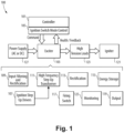
- FIG. 1 an illustrative view of an embodiment of a system in accordance with the disclosure is shown in Fig. 1 and is designated generally by reference character 100.
- FIGs. 2-7 Other embodiments and/or aspects of this disclosure are shown in Figs. 2-7 .
- Certain embodiments described herein can be used to provide lighter and smaller engine ignition systems, for example.
- an engine ignition system 100 can include a multifunction controller 101, and an exciter 103 operatively connected to the multifunction controller 101.
- the multifunction controller 101 can be configured to control the exciter 103 to output an ignition voltage.
- the multifunction controller 101 can be configured to perform at least one other engine control function (e.g., engine speed in response to throttle commands, for example). Any suitable other engine control function is contemplated herein.
- the multifunction controller 101 can be located in low temperature area (e.g., thermally isolated from a hot area of an engine), for example.
- the exciter 103 can be located in a high temperature area and housed separately from the multifunction controller 101.
- the two can be connected via one or more cables, for example (and/or wirelessly if suitable power and/or signal transfer is accounted for).
- the multifunction controller 101 can include an ignition switch mode control module 105.
- the multifunction controller 101 can be a FADEC (full authority digital engine controller), for example (e.g., having the mode control module added thereto).
- Hardware that already exists on the FADEC can be utilized to the maximum extent to integrate the mode control module 105 and/or any other suitable control function, thereby reducing weight and component count of the overall system.
- the exciter 103 can include one or more ignition step up drivers 107.
- the exciter 103 can include any suitable hardware configured to function as an exciter.
- the exciter 103 includes an input filtering and rectification device 109, a high frequency step up transformer 111 (e.g., connected to the ignition step up drivers), a rectifier 113, an energy storage device 115 (e.g., a capacitor), a firing switch 117 connected between the energy storage device 115 and an output 119 (e.g., connected to igniter 121 via leads 123), and a monitor 125 configured to monitor a state of the energy storage device 115 and communicate with the controller 101.
- the multifunction controller 201 can include the one or more ignition step up drivers 207, e.g, integrated therewith.
- the system 100, 200 can include a power supply 127 directly connected to the exciter 103.
- a system 300 can include a power supply 127 connected to the multifunction controller 101 to provide power to the one or more step up drivers 207.
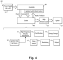
- a system 400 can have a power supply 127 that can be provided to the controller 101 and the controller 101 can be configured to provide power to the exciter 103 (and the exciter 403 may not need any input power filtering or rectification).
- the exciter 103 can include an energy storage device 115, and a firing switch 117 connected between the energy storage device 115 and an ignitor output 119.
- the firing switch 117 can be configured to be controlled by the multifunction controller 101.
- the firing switch 117 can be configured to automatically close when the charge on the energy storage device 115 reaches an ignition threshold without control from the controller 101.
- the exciter 103 can include a step-up transformer 111 connected between a power supply input 529 and the energy storage device 115.
- the exciter 103 can include a monitor 123 connected to the energy storage device 115 to monitor a state of the energy storage device 115.
- the monitor 123 can be connected to the multifunction controller 101 to provide data to the multifunction controller 101.
- the exciter 103 can include a step up driver 531 operatively connected to the step up transformer 111 to control the step up transformer 111.
- the step up driver 531 can be controlled by the mode control module 105.
- the exciter 103 can include a power switch driver 533 operatively connected to the firing switch 117 to control the firing switch 117.
- the power switch driver 533 can be controlled by the mode control module 105.
- the multifunction controller 101 can include a first driver 535 and a second driver 537 connected to and controlled by a logic block 539.
- the logic block 539 can be connected to a processing module 541 that includes the mode control module 105 (or a portion thereof), for example.
- the step up driver 531 can be controlled by the mode control module 105 via the first driver 535 through the logic block 539 based on commands from the processing module 541.
- the power switch driver 533 can be controlled by the mode control module 105 via the second driver 537 through the logic block 539 based on commands from the processing module 541.
- the multifunction controller 101 can include a precision clock 543 operatively connected to the logic 539 and/or the processing module 541.
- the multifunction controller 101 can include a data acquisition module 545 operatively connected to the monitor 125 of the exciter 103.
- Fig. 5 shows an embodiment of a disambiguation of a system 100
- any other suitable disambiguation of components to reduce size, weight, and/or part count is contemplated herein.
- the multifunction controller 101 may only require the addition of a physical logic block 539 and/or the drivers 535 and 537. All other components may already exist in the controller 101 (e.g., the clock 543 and data acquisition module 545) depending on the other functions handled by the controller 101 (e.g., which can be a FADEC), and many software functions can be hosted on common hardware.
- Fig. 6 is a chart showing waveforms of an embodiment of system storage voltage and igniter voltage, for example.
- the example shown is running at 25 kHz.
- the flyback transformer can be small, with a 10 uH primary inductance.
- Parallel circuits can be used for Main and Augmentation, and can run independently.
- the SM signal applied has resulted in 3 sparks, followed by a commanded shunt condition to shut the power off.
- the spark rate is approximately 28 sparks per second.
- the spark rate can be as slow as desired.
- Fig. 7 is a circuit diagram of an embodiment of an exciter in accordance with this disclosure. Shown is exciter input rectification, switch mode driver, flyback transformer, and energy storage, and showing the controller input command. Any other suitable circuit arrangement for an exciter is contemplated herein.
- a method can include integrating heat sensitive logic components of an engine ignition system in an existing engine controller thereby reducing weight of the engine ignition system and thermally protecting the heat sensitive logic components of the engine ignition system.
- the method can include thermally isolating the existing engine controller from an exciter of the engine ignition system.
- the method can include any other suitable method(s) and/or portion(s) thereof.
- Embodiments can shift hardware locations and functions in a way that allows each component to exist in an acceptable thermal environment, while also realizing a weight and part count decrease.
- Certain modern controllers e.g., FADECS
- FADECS have excess computing power can handle added functions without compromising functionality or speed.
- Embodiments require less circuitry (size, part count, and/or weight) than even the simplest of traditional systems. For example, traditional mode control hardware required 6 square inches of space, but this functionality integrated into the multifunction controller allows it to be much smaller, e.g., less than 1 square inch of added hardware.
- the only thing physically added to the controller hardware can be the ignition switch mode control module (e.g., a PWM driver and/or related components).
- Embodiments of a mode control module can be directly connected to the ignition step up drivers and provide a PWM signal to the step up driver.
- Certain embodiments can move the step up drive to the controller, can have power wired to a high frequency power drive, and/or can have power routed through the controller.
- high voltage control can be directly commanded by the FADEC of the engine.
- controller can already have extensive input filtering, internal power supplies, computational resources, thermal management, circuit board assemblies for packaging the circuits, and vibration isolation.
- the controller can be a highly sophisticated electronic unit that incorporates a tremendously capable computer, memory, and a multitude of different input and output types, such as sensor interfaces and effector drivers.
- the previous simple on/off command to the exciter can be replaced with a switch mode supply command, and the simple health circuit can be replaced with more precise voltage feedback.
- resources that already reside inside the controller those functions can be eliminated from the exciter and replaced by more capable hardware in the controller.
- embodiments can provide the robust capability of the older technology, especially temperature and vibration capability, and also provide the advantages of more modern technology.
- the controller in embodiments can provide a suitable high frequency drive signal to directly drive the ignition step up driver in the exciter.
- the high frequency step up transformer in the exciter can be for example in one embodiment a flyback type transformer (e.g., as shown in Fig. 5 ).
- a transistor switch in the exciter can be used as the ignition step up driver.
- the switch frequency could be as low as 25 kHz, or much higher, for example as high as 100 kHz or more.
- a lower frequency can minimize EMI concerns and reduce the switching device power dissipation, whereas a higher frequency allows for smaller magnetics and filter components.
- Feedback from the exciter provided to the controller can show the value of stored internal charge within the exciter.
- the controller can provide a SM (Switch Mode) signal to the exciter, causing the ignition driver to cycle in step with the input signal, thereby switching the flyback transformer, which, over time, charges up the exciter internal energy storage device at a desired rate.
- SM Switch Mode
- the firing switch in the exciter can apply the stored energy to the output of the exciter, resulting in a spark at the igniter plug.
- the firing switch can take on any suitable forms. It can be a gas discharge tube, a solid state switch, for example, or any other suitable firing switch.
- the switch can be set up to fire at a preset voltage or it could be set up to fire based on a command from the controller.
- the firing switch does not isolate the output, the charged voltage can be monitored for a decay when not charging, which can indicate that the dielectric withstand capability of the HTL or igniter has been compromised.
- the exciter can also be operated in a way that it attempts to fire at lower voltages than the minimum withstand capability of the igniter, to detect faults in the high tension leads and igniter such as dirty or cracked insulation. If there is a discharge of energy at a voltage lower than the required minimum, it can indicate there is a problem in the system.
- the controller can vary the pulse width of the driver frequency as necessary to charge the system.
- a lower pulse width produces a slower charge rate but lower current draw from the main supply.
- a wider pulse width will allow the system to be charged more quickly.
- the charge time can be tailored for the input power supply capability and also it can be made long enough to allow for frequent sampling by the feedback circuits which are used by the controller to monitor the system.
- the controller can again start the switch sequence, causing another charge-discharge cycle to occur. This sequence can be repeated as necessary until the time duration required for the spark sequence is complete.
- the ignition command is provided continuously after engine start, relying on the pressure of the running engine to quench (or shut off) spark production when it is not needed.
- High tension systems for example greater than 12,000V peak output pulse, have spark plug designs that auto-quench at high combustor pressure so they don't continue to spark once the engine is fully running.
- Low tension systems (less than the typical 12,000V peak pulse voltage of high tension systems) have spark plug designs that will not auto-quench, and unless commanded off will continue to spark regardless of engine operating condition.
- the systems share a common feature which is to raise a low voltage input supply to a high voltage that is the basis for the energy stored in the exciter, and upon receiving the command to produce sparks the exciter provides the rest of the functionality independently until commanded to turn off.
- One benefit of the older technology is that the components are simple and are available in relatively high temperature capability which is necessary for the equipment to survive in the high temperature environment that is present where the exciters are mounted on the engine.
- Older systems can use components that have been around for many years, which can form a simple system, but the components may be large and heavy, and in some cases prone to obsolescence or procurement issues. These work with either AC supplies, or simple chopper type DC supplies.
- More modern systems can take advantage of smaller, lighter components.
- functions such as the firing switch can be upgraded to more modern devices. This runs at a higher frequency which allows for smaller magnetic components but this frequency is generated internally with various internal power supplies and control circuits.
- the additional functions are shown to the lower left of the figure.
- the system now can use smaller lighter components and can have better monitoring capability, there is an additional burden of requiring the extra power, control, and driver circuits shown.
- the additional complication of these circuits requiring functionality provided by integrated circuits, which in standard electronics devices made available in industry have a more limited temperature range than the typical installation requires. These components also are more susceptible to the high vibration environment present in the exciter.
- An alternate architecture is proposed that uses a more optimally integrated approach between the controller and the exciter to provide weight savings, increased reliability, more flexible capability, enhanced functions, and higher temperature capability of the exciter.
- Embodiments can include any suitable computer hardware and/or software module(s) to perform any suitable function (e.g., as disclosed herein).
- aspects of the present disclosure may be embodied as a system, method or computer program product. Accordingly, aspects of this disclosure may take the form of an entirely hardware embodiment, an entirely software embodiment (including firmware, resident software, micro-code, etc.), or an embodiment combining software and hardware aspects, all possibilities of which can be referred to herein as a "circuit,” “module,” or “system.”
- a “circuit,” “module,” or “system” can include one or more portions of one or more separate physical hardware and/or software components that can together perform the disclosed function of the "circuit,” “module,” or “system”, or a “circuit,” “module,” or “system” can be a single self-contained unit (e.g., of hardware and/or software).
- aspects of this disclosure may take the form of a computer program product embodied in one or more computer readable medium(s) having computer readable program code embodied thereon.
- the computer readable medium may be a computer readable signal medium or a computer readable storage medium.
- a computer readable storage medium may be, for example, but not limited to, an electronic, magnetic, optical, electromagnetic, infrared, or semiconductor system, apparatus, or device, or any suitable combination of the foregoing.
- a computer readable storage medium may be any tangible medium that can contain, or store a program for use by or in connection with an instruction execution system, apparatus, or device.
- a computer readable signal medium may include a propagated data signal with computer readable program code embodied therein, for example, in baseband or as part of a carrier wave. Such a propagated signal may take any of a variety of forms, including, but not limited to, electro-magnetic, optical, or any suitable combination thereof.
- a computer readable signal medium may be any computer readable medium that is not a computer readable storage medium and that can communicate, propagate, or transport a program for use by or in connection with an instruction execution system, apparatus, or device.
- Program code embodied on a computer readable medium may be transmitted using any appropriate medium, including but not limited to wireless, wireline, optical fiber cable, RF, etc., or any suitable combination of the foregoing.
- Computer program code for carrying out operations for aspects of this disclosure may be written in any combination of one or more programming languages, including an object oriented programming language such as Java, Smalltalk, C++ or the like and conventional procedural programming languages, such as the "C" programming language or similar programming languages.
- the program code may execute entirely on the user's computer, partly on the user's computer, as a stand-alone software package, partly on the user's computer and partly on a remote computer or entirely on the remote computer or server.
- the remote computer may be connected to the user's computer through any type of network, including a local area network (LAN) or a wide area network (WAN), or the connection may be made to an external computer (for example, through the Internet using an Internet Service Provider).
- LAN local area network
- WAN wide area network
- Internet Service Provider for example, AT&T, MCI, Sprint, EarthLink, MSN, GTE, etc.
- These computer program instructions may also be stored in a computer readable medium that can direct a computer, other programmable data processing apparatus, or other devices to function in a particular manner, such that the instructions stored in the computer readable medium produce an article of manufacture including instructions which implement the function/act specified in the flowchart and/or block diagram block or blocks.
- the computer program instructions may also be loaded onto a computer, other programmable data processing apparatus, or other devices to cause a series of operational steps to be performed on the computer, other programmable apparatus or other devices to produce a computer implemented process such that the instructions which execute on the computer or other programmable apparatus provide processes for implementing the functions/acts specified herein.
- any numerical values disclosed herein can be exact values or can be values within a range. Further, any terms of approximation (e.g., “about”, “approximately”, “around”) used in this disclosure can mean the stated value within a range. For example, in certain embodiments, the range can be within (plus or minus) 20%, or within 10%, or within 5%, or within 2%, or within any other suitable percentage or number as appreciated by those having ordinary skill in the art (e.g., for known tolerance limits or error ranges).
- a reference to "A and/or B", when used in conjunction with open-ended language such as “comprising” can refer, in one embodiment, to A only (optionally including elements other than B); in another embodiment, to B only (optionally including elements other than A); in yet another embodiment, to both A and B (optionally including other elements); etc.
Landscapes
- Engineering & Computer Science (AREA)
- Chemical & Material Sciences (AREA)
- Combustion & Propulsion (AREA)
- Mechanical Engineering (AREA)
- General Engineering & Computer Science (AREA)
- Ignition Installations For Internal Combustion Engines (AREA)
Applications Claiming Priority (1)
| Application Number | Priority Date | Filing Date | Title |
|---|---|---|---|
| US17/728,612 US12359648B2 (en) | 2022-04-25 | 2022-04-25 | Engine ignition systems |
Publications (3)
| Publication Number | Publication Date |
|---|---|
| EP4269784A2 true EP4269784A2 (de) | 2023-11-01 |
| EP4269784A3 EP4269784A3 (de) | 2024-01-17 |
| EP4269784B1 EP4269784B1 (de) | 2026-01-21 |
Family
ID=86095752
Family Applications (1)
| Application Number | Title | Priority Date | Filing Date |
|---|---|---|---|
| EP23168775.7A Active EP4269784B1 (de) | 2022-04-25 | 2023-04-19 | Zündsystem für brennkraftmaschine |
Country Status (2)
| Country | Link |
|---|---|
| US (1) | US12359648B2 (de) |
| EP (1) | EP4269784B1 (de) |
Cited By (1)
| Publication number | Priority date | Publication date | Assignee | Title |
|---|---|---|---|---|
| EP4382741A3 (de) * | 2022-12-08 | 2024-07-17 | Hamilton Sundstrand Corporation | Motorzündsysteme und steuerungsverfahren dafür |
Families Citing this family (1)
| Publication number | Priority date | Publication date | Assignee | Title |
|---|---|---|---|---|
| US12529341B2 (en) * | 2024-06-11 | 2026-01-20 | General Electric Company | Ignition system and method of operating a combustion engine |
Family Cites Families (28)
| Publication number | Priority date | Publication date | Assignee | Title |
|---|---|---|---|---|
| JPS5945832B2 (ja) * | 1980-09-29 | 1984-11-08 | 日産自動車株式会社 | 点火時期制御装置 |
| US5065073A (en) * | 1988-11-15 | 1991-11-12 | Frus John R | Apparatus and method for providing ignition to a turbine engine |
| JPH03294660A (ja) * | 1990-04-11 | 1991-12-25 | Mitsubishi Electric Corp | エンジン始動補助装置 |
| US5045964A (en) * | 1990-04-30 | 1991-09-03 | Motorola, Inc. | Thermal clamp for an ignition coil driver |
| CA2128036C (en) * | 1993-07-15 | 2003-11-04 | Howard Vincent Bonavia | Ignition system using multiple gated switches with variable discharge energy levels and rates |
| US5941926A (en) * | 1996-04-10 | 1999-08-24 | Snap-On Technologies, Inc. | Engine analyzer with cylinder triggering of oscilloscope display having fixed-time sweep |
| US6195247B1 (en) | 1998-06-02 | 2001-02-27 | Pratt & Whitney Canada | Exciter controlled by FADEC system |
| JP2000130250A (ja) * | 1998-10-29 | 2000-05-09 | Kokusan Denki Co Ltd | 内燃機関用制御装置 |
| JP4135837B2 (ja) * | 1999-02-23 | 2008-08-20 | ヤマハマリン株式会社 | 燃料噴射弁固着解除装置 |
| JP2001107750A (ja) * | 1999-10-05 | 2001-04-17 | Honda Motor Co Ltd | 航空機用ガスタービン・エンジンの制御装置 |
| US6516773B2 (en) * | 2001-05-03 | 2003-02-11 | Caterpillar Inc | Method and apparatus for adjusting the injection current duration of each fuel shot in a multiple fuel injection event to compensate for inherent injector delay |
| US6603216B2 (en) * | 2001-10-10 | 2003-08-05 | Champion Aerospace Inc. | Exciter circuit with ferro-resonant transformer network for an ignition system of a turbine engine |
| JP4428186B2 (ja) * | 2004-10-12 | 2010-03-10 | 株式会社デンソー | エンジン始動補助システム |
| JP4749981B2 (ja) * | 2005-12-28 | 2011-08-17 | 日立オートモティブシステムズ株式会社 | 内燃機関の可変動弁装置 |
| KR20080016105A (ko) * | 2006-08-17 | 2008-02-21 | 지멘스 오토모티브 주식회사 | 엔진 제어 유닛 인쇄 회로 기판 |
| US8027142B2 (en) * | 2007-10-25 | 2011-09-27 | Honeywell International Inc. | Current-protected driver circuit for ignition exciter unit |
| US8266885B2 (en) * | 2008-12-23 | 2012-09-18 | General Electric Company | Method and systems for adaptive ignition energy |
| US9013856B2 (en) * | 2011-08-29 | 2015-04-21 | Honeywell International Inc. | Ignition exciter system and ignition exciter circuit |
| JP6063677B2 (ja) * | 2012-09-06 | 2017-01-18 | ローム株式会社 | 信号検出回路及びイグナイタ |
| US9399954B2 (en) * | 2014-03-17 | 2016-07-26 | Unison Industries, Llc | Ignition exciter discharge switch |
| US10641179B2 (en) * | 2016-11-07 | 2020-05-05 | General Electric Company | System and method for starting gas turbine engines |
| US10801414B2 (en) * | 2017-01-24 | 2020-10-13 | Honeywell International Inc. | Gas turbine engine including a rectifierless electronic control unit and method for supplying power to same |
| JP6951900B2 (ja) * | 2017-08-04 | 2021-10-20 | 株式会社Soken | 内燃機関用の点火装置 |
| FR3072762B1 (fr) * | 2017-10-23 | 2019-11-08 | Airbus Operations (S.A.S.) | Systeme d'allumage d'une turbomachine d'aeronef |
| US11273927B2 (en) | 2018-04-04 | 2022-03-15 | Honeywell International Inc. | Micro-auxiliary power units |
| US11002238B2 (en) | 2019-02-13 | 2021-05-11 | Pratt & Whitney Canada Corp. | Method and system for starting an engine |
| US11578661B2 (en) | 2019-09-19 | 2023-02-14 | Pratt & Whitney Canada Corp. | Systems and methods for starting a gas turbine engine |
| US11506076B2 (en) | 2020-01-23 | 2022-11-22 | Pratt & Whitney Canada Corp. | Methods and systems for starting an engine |
-
2022
- 2022-04-25 US US17/728,612 patent/US12359648B2/en active Active
-
2023
- 2023-04-19 EP EP23168775.7A patent/EP4269784B1/de active Active
Cited By (2)
| Publication number | Priority date | Publication date | Assignee | Title |
|---|---|---|---|---|
| EP4382741A3 (de) * | 2022-12-08 | 2024-07-17 | Hamilton Sundstrand Corporation | Motorzündsysteme und steuerungsverfahren dafür |
| US12486822B2 (en) | 2022-12-08 | 2025-12-02 | Hamilton Sundstrand Corporation | Engine ignition systems and control methods therefor |
Also Published As
| Publication number | Publication date |
|---|---|
| EP4269784A3 (de) | 2024-01-17 |
| US20230340934A1 (en) | 2023-10-26 |
| US12359648B2 (en) | 2025-07-15 |
| EP4269784B1 (de) | 2026-01-21 |
Similar Documents
| Publication | Publication Date | Title |
|---|---|---|
| US5065073A (en) | Apparatus and method for providing ignition to a turbine engine | |
| EP4269784B1 (de) | Zündsystem für brennkraftmaschine | |
| US5399942A (en) | Apparatus and method for providing ignition to a turbine engine | |
| US5148084A (en) | Apparatus and method for providing ignition to a turbine engine | |
| EP0434217B1 (de) | Plasma-Zündanlage | |
| US6670777B1 (en) | Ignition system and method | |
| EP3443218B1 (de) | Verfahren und vorrichtung zur steuerung eines zündsystems | |
| EP3374626B1 (de) | Verfahren und vorrichtung zur steuerung eines zündsystems | |
| US5572135A (en) | Diagnostic apparatus and methods for ignition circuits | |
| EP4382741B1 (de) | Motorzündsysteme und steuerungsverfahren dafür | |
| US5508618A (en) | Coreless detector for ignition dischage current | |
| EP0628719B1 (de) | Zündapparat mit einer Niedrigspannungskapazitätsentladungsselbsttriggerschaltung | |
| US20150260146A1 (en) | Method and apparatus of charging an engine ignition system | |
| CN108352247B (zh) | 用于将交流电传递到火花塞的点火线圈 | |
| EP3352352B1 (de) | Gasturbinenmotor mit einer gleichrichterfreien elektronischen steuereinheit und verfahren zur stromversorgung dafür | |
| US20210087973A1 (en) | System and method for starting a gas turbine engine | |
| US20140034032A1 (en) | Smart ignition coil with integrated controller | |
| CN102486151B (zh) | 双能源独立点火线圈 | |
| JP3023864B2 (ja) | 高圧コード装置 | |
| Abarna et al. | Design and Simulation of Isolated AC-DC Fly Back Conversion System for High Energy Ignition Unit of Gas Turbine Engines | |
| Mahajan et al. | Novel exciter circuit for ignition of gas turbine engines in aerospace applications | |
| AU2021240225A1 (en) | A controller and method for controlling an ignition coil when starting a spark ignition internal combustion engine | |
| CA2206781C (en) | Apparatus and method for providing ignition to a turbine engine | |
| JPH1089211A (ja) | 点火制御装置 | |
| US10082123B2 (en) | Electronic spark timing control system for an AC ignition system |
Legal Events
| Date | Code | Title | Description |
|---|---|---|---|
| PUAI | Public reference made under article 153(3) epc to a published international application that has entered the european phase |
Free format text: ORIGINAL CODE: 0009012 |
|
| STAA | Information on the status of an ep patent application or granted ep patent |
Free format text: STATUS: THE APPLICATION HAS BEEN PUBLISHED |
|
| AK | Designated contracting states |
Kind code of ref document: A2 Designated state(s): AL AT BE BG CH CY CZ DE DK EE ES FI FR GB GR HR HU IE IS IT LI LT LU LV MC ME MK MT NL NO PL PT RO RS SE SI SK SM TR |
|
| PUAL | Search report despatched |
Free format text: ORIGINAL CODE: 0009013 |
|
| AK | Designated contracting states |
Kind code of ref document: A3 Designated state(s): AL AT BE BG CH CY CZ DE DK EE ES FI FR GB GR HR HU IE IS IT LI LT LU LV MC ME MK MT NL NO PL PT RO RS SE SI SK SM TR |
|
| RIC1 | Information provided on ipc code assigned before grant |
Ipc: F02P 11/06 20060101ALN20231208BHEP Ipc: F02P 15/00 20060101AFI20231208BHEP |
|
| STAA | Information on the status of an ep patent application or granted ep patent |
Free format text: STATUS: REQUEST FOR EXAMINATION WAS MADE |
|
| 17P | Request for examination filed |
Effective date: 20240716 |
|
| RBV | Designated contracting states (corrected) |
Designated state(s): AL AT BE BG CH CY CZ DE DK EE ES FI FR GB GR HR HU IE IS IT LI LT LU LV MC ME MK MT NL NO PL PT RO RS SE SI SK SM TR |
|
| STAA | Information on the status of an ep patent application or granted ep patent |
Free format text: STATUS: EXAMINATION IS IN PROGRESS |
|
| 17Q | First examination report despatched |
Effective date: 20250109 |
|
| GRAP | Despatch of communication of intention to grant a patent |
Free format text: ORIGINAL CODE: EPIDOSNIGR1 |
|
| STAA | Information on the status of an ep patent application or granted ep patent |
Free format text: STATUS: GRANT OF PATENT IS INTENDED |
|
| INTG | Intention to grant announced |
Effective date: 20250910 |
|
| GRAS | Grant fee paid |
Free format text: ORIGINAL CODE: EPIDOSNIGR3 |
|
| GRAA | (expected) grant |
Free format text: ORIGINAL CODE: 0009210 |
|
| STAA | Information on the status of an ep patent application or granted ep patent |
Free format text: STATUS: THE PATENT HAS BEEN GRANTED |
|
| AK | Designated contracting states |
Kind code of ref document: B1 Designated state(s): AL AT BE BG CH CY CZ DE DK EE ES FI FR GB GR HR HU IE IS IT LI LT LU LV MC ME MK MT NL NO PL PT RO RS SE SI SK SM TR |
|
| REG | Reference to a national code |
Ref country code: CH Ref legal event code: F10 Free format text: ST27 STATUS EVENT CODE: U-0-0-F10-F00 (AS PROVIDED BY THE NATIONAL OFFICE) Effective date: 20260121 |
|
| REG | Reference to a national code |
Ref country code: DE Ref legal event code: R096 Ref document number: 602023010886 Country of ref document: DE |
|
| REG | Reference to a national code |
Ref country code: IE Ref legal event code: FG4D |
|
| PGFP | Annual fee paid to national office [announced via postgrant information from national office to epo] |
Ref country code: FR Payment date: 20260319 Year of fee payment: 4 |