EP4269230A1 - Novel windscreen architecture and aircraft provided with such a windscreen - Google Patents
Novel windscreen architecture and aircraft provided with such a windscreen Download PDFInfo
- Publication number
- EP4269230A1 EP4269230A1 EP23170263.0A EP23170263A EP4269230A1 EP 4269230 A1 EP4269230 A1 EP 4269230A1 EP 23170263 A EP23170263 A EP 23170263A EP 4269230 A1 EP4269230 A1 EP 4269230A1
- Authority
- EP
- European Patent Office
- Prior art keywords
- aircraft
- coating layer
- fold
- coated
- peripheral edge
- Prior art date
- Legal status (The legal status is an assumption and is not a legal conclusion. Google has not performed a legal analysis and makes no representation as to the accuracy of the status listed.)
- Pending
Links
- 239000011247 coating layer Substances 0.000 claims abstract description 37
- 230000002093 peripheral effect Effects 0.000 claims abstract description 31
- 229910052500 inorganic mineral Inorganic materials 0.000 claims abstract description 28
- 239000011707 mineral Substances 0.000 claims abstract description 28
- 239000011521 glass Substances 0.000 claims abstract description 27
- 239000000463 material Substances 0.000 claims abstract description 27
- 239000012780 transparent material Substances 0.000 claims abstract description 7
- 239000011368 organic material Substances 0.000 claims abstract description 6
- CWRVKFFCRWGWCS-UHFFFAOYSA-N Pentrazole Chemical compound C1CCCCC2=NN=NN21 CWRVKFFCRWGWCS-UHFFFAOYSA-N 0.000 claims description 3
- 239000000853 adhesive Substances 0.000 claims 1
- 230000001070 adhesive effect Effects 0.000 claims 1
- 239000003292 glue Substances 0.000 description 9
- 239000010410 layer Substances 0.000 description 4
- VYPSYNLAJGMNEJ-UHFFFAOYSA-N silicon dioxide Inorganic materials O=[Si]=O VYPSYNLAJGMNEJ-UHFFFAOYSA-N 0.000 description 3
- 239000011248 coating agent Substances 0.000 description 2
- 238000000576 coating method Methods 0.000 description 2
- 229910052751 metal Inorganic materials 0.000 description 2
- 239000002184 metal Substances 0.000 description 2
- 229920001296 polysiloxane Polymers 0.000 description 2
- 238000007789 sealing Methods 0.000 description 2
- 125000006850 spacer group Chemical group 0.000 description 2
- VVQNEPGJFQJSBK-UHFFFAOYSA-N Methyl methacrylate Chemical compound COC(=O)C(C)=C VVQNEPGJFQJSBK-UHFFFAOYSA-N 0.000 description 1
- 229920005372 Plexiglas® Polymers 0.000 description 1
- 238000005299 abrasion Methods 0.000 description 1
- NIXOWILDQLNWCW-UHFFFAOYSA-N acrylic acid group Chemical group C(C=C)(=O)O NIXOWILDQLNWCW-UHFFFAOYSA-N 0.000 description 1
- 229910052782 aluminium Inorganic materials 0.000 description 1
- XAGFODPZIPBFFR-UHFFFAOYSA-N aluminium Chemical compound [Al] XAGFODPZIPBFFR-UHFFFAOYSA-N 0.000 description 1
- 230000010354 integration Effects 0.000 description 1
- 238000003754 machining Methods 0.000 description 1
- 238000000465 moulding Methods 0.000 description 1
- 230000000149 penetrating effect Effects 0.000 description 1
- 229920003229 poly(methyl methacrylate) Polymers 0.000 description 1
- 239000004417 polycarbonate Substances 0.000 description 1
- 229920000515 polycarbonate Polymers 0.000 description 1
- 239000004926 polymethyl methacrylate Substances 0.000 description 1
- 230000001681 protective effect Effects 0.000 description 1
- 239000010453 quartz Substances 0.000 description 1
- 230000003014 reinforcing effect Effects 0.000 description 1
- 239000011347 resin Substances 0.000 description 1
- 229920005989 resin Polymers 0.000 description 1
- 230000000717 retained effect Effects 0.000 description 1
- 239000000377 silicon dioxide Substances 0.000 description 1
- 239000003190 viscoelastic substance Substances 0.000 description 1
- XLYOFNOQVPJJNP-UHFFFAOYSA-N water Substances O XLYOFNOQVPJJNP-UHFFFAOYSA-N 0.000 description 1
Images

Classifications
-
- B—PERFORMING OPERATIONS; TRANSPORTING
- B64—AIRCRAFT; AVIATION; COSMONAUTICS
- B64C—AEROPLANES; HELICOPTERS
- B64C1/00—Fuselages; Constructional features common to fuselages, wings, stabilising surfaces or the like
- B64C1/14—Windows; Doors; Hatch covers or access panels; Surrounding frame structures; Canopies; Windscreens accessories therefor, e.g. pressure sensors, water deflectors, hinges, seals, handles, latches, windscreen wipers
- B64C1/1476—Canopies; Windscreens or similar transparent elements
- B64C1/1492—Structure and mounting of the transparent elements in the window or windscreen
Definitions
- the present invention relates to an aircraft windshield and an aircraft provided with such a windshield.
- the invention applies to all types of aircraft equipped with a windshield and in particular to civil and military aircraft as well as helicopters.
- the windshield includes a glass comprising several plies of varied transparent materials making it possible to offer structural characteristics adapted to the necessary mechanical resistance.
- the ice must in fact resist variations in pressure and temperature, impacts of different types (birds, hail, scratches, abrasion, etc.).
- the transparent materials used can be of mineral origin (glass, quartz, silica, etc. or combination of these) or of organic origin (acrylic, polycarbonate, resins, polymethylmethacrylate more commonly called plexiglass (registered trademark), etc. . or combination thereof).
- the glasses can also include a combination of folds of organic origin and a fold of mineral origin generally of the glass positioned most outside; one of its faces is therefore in the open air.
- the windows are fixed in an opening made in the structure of the front end of the aircraft, at the level of the cockpit on a suitable frame forming part of the structure of the aircraft.
- the windows can be pinched at their peripheral edge between the frame and a clamp secured to the structure of the aircraft using screw-nut type fasteners for example or directly bolted at their peripheral edge to supervision.
- the windshield comprises a glass comprising several folds 10 of various transparent materials.
- the thicker folds are called structural folds.
- a glue 30 covers the different surfaces in contact so as to bind them together.
- the ice is fixed in an opening in the structure of the nose of the aircraft, at the level of the cockpit on a suitable frame 12.
- the glass is pinched at its peripheral edge between the frame 12 and a clamping flange 14 secured to the structure of the aircraft using screw-nut type fasteners 16.
- This type of assembly is called a flange assembly. It requires the addition of elements such as a peripheral flange making the assembly complex but possible for windows with structural folds made of material of mineral origin.
- a glass having structural folds made of material of organic origin will generally be fixed to the structure of the aircraft by a direct bolting principle, the flexibility of the materials allowing it.
- a glass having structural folds made of material of mineral origin will preferably be fixed to the structure following a flange assembly principle of the type described above in the patent mentioned allowing fixing by bolt outside the folds without them. to cross.
- the present invention aims to propose a new ice windshield architecture having at least one fold of internal mineral material making it possible to overcome all of the aforementioned drawbacks and in particular making it possible to choose the type of assembly more freely.
- the present invention relates to an aircraft windshield comprising a glass comprising at least one fold of transparent material of mineral origin and having a peripheral edge, characterized in that at least one of the folds of the glass made of mineral material is/are coated with a coating layer of viscoelastic transparent organic material over its entire surface including the peripheral edge.
- the coating of folds of mineral material in a glass with a layer of viscoelastic material allows them to be protected by reinforcing their solidity. Furthermore, the coating layer is used to improve the seal and facilitate the assembly of the windshield on the aircraft structure by allowing, for example, fixing by direct bolting despite the use of layers of mineral material.
- the invention provides at least one of the following optional characteristics, taken individually or in combination.
- Each of the layers of mineral material in the ice is coated.
- An outer ply of uncoated mineral material is provided, the outer face of which is the outermost face of the ice and the inner face is adjoined to the outer face of the outermost coating layer by the via a glue and in that each of the internal folds is coated.
- the coating layer forms a one-piece envelope.
- the coating layer is made of Opticor material (registered trademark).
- the coating layer includes an extension at the entire peripheral edge of the ply which has a through opening.
- the mineral material is glass.
- the present invention also relates to an aircraft comprising a frame forming part of the primary structure of the aircraft and a windshield associated with said frame having one or more of the aforementioned characteristics.
- the coated fold(s) and the coating layer are held using a flange fixing.
- screw-nut type fixing means pass through the extension through the opening to enclose the coating layer and the coated fold(s).
- FIG 2 represents an aircraft 32 comprising a front end 34 in which a cockpit is located.
- the front tip 34 includes a windshield 36 provided with at least one glass 38.
- at least one window 38 of the aircraft windshield 36 comprises at least one ply 40 of transparent material of mineral origin.
- the fold(s) 40 have a peripheral edge 42.
- the fold(s) 40 have an exterior face 40a facing the outside of the aircraft as opposed to the interior face 40b facing the cockpit.
- exterior/interior will be used in the remainder of the description to indicate for the exterior term a greater proximity to the exterior of the aircraft and interior to the interior of the aircraft, i.e. in the example illustrated, the position piloting.
- the glass 38 comprises a fold 40 of transparent mineral material and in the example illustrated of glass.
- the glass 38 is fixed to the primary structure of the aircraft 32 and more precisely to a part called the frame 44 which is part of it by a fixing system explained below.
- the frame 44 encircles the mirror 38.
- At least one fold 40 of the glass 38 made of transparent mineral material is(are) coated with a layer 46 called coating of viscoelastic transparent organic material over the entirety of its/their surface including the/their edge 42 peripheral.
- the coating layer 46 completely envelops the fold 40.
- the coating layer 46 has an exterior face 46a closest to the exterior environment of the aircraft and an opposite interior face 46b.
- the transparent viscoelastic organic material could for example be Opticor (registered trademark).
- the whole is obtained by molding in a mold designed so that the whole adapts perfectly to the frame.
- glue 47 is used to adhere the plies to each other as illustrated in the figures 5 and 6 .
- the glue is a polyvintethane glue, called PVB glue.
- the glue 47 can also be applied to the entire surface of the fold, namely the faces 40a and 40b as well as to the peripheral edge 42 in order to improve overall cohesion.
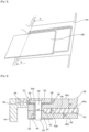
- the coating layer 46 includes an extension, called extension 48, at the peripheral edge 42 of the fold over its entire circumference.
- the coating layer 46 has a thickness e2 ( Figure 4 ), e"2 ( Figure 6 ) more important at the level of the peripheral edge 42 of the fold to constitute this extension 48.
- the extension 48 has through orifices 49 distributed over the entire circumference of the fold and according to a possible shape, regularly distributed at least over the majority of the extension .
- only one internal fold 40 is provided for the sake of simplification in the description but several coated folds could be provided. Identical elements retain the same references from one embodiment to another.
- the thickness of the coating layer is uniform over the entire surface of each face 40a, 40b of the fold 40 but differs from one face 40a (thickness e1) to the other 40b (thickness e3).
- the thickness e1 at its exterior face 40a is greater than the thickness e3 at its interior face 40b so as to allow the integration of a retaining device 52.
- the retaining device 52 comprising an outer plate 54 and an inner plate 56, made for example of metal and for illustration purposes of aluminum, makes it possible to sandwich the peripheral edge 53 of the coating layer 46 with the peripheral edge 42 of the fold 40.
- the coating layer 46 is hollowed out at the level of the edge 53 peripheral of its external face 46a.
- the formed cavity 58 open to the outside makes it possible to receive on the coating layer 46 the outer plate 54 of the retaining device 52 in such a way that its outer face 54a is flush with the outer face 46a of the coating layer.
- the space between the outer plate 54 of the retaining device and the coating layer 46 is filled by a seal 60.
- the extension has a thickness h equal to the sum of the thickness of the fold h1 and the thickness of the coating layer e1 and e3 on both sides of the fold 40, reduced by the thickness h2 of the cavity 58 and the seal 60.
- the outer plate 54 is intended to be attached to the outer face 46a of the coating layer and the inner plate 56 to the inner face 46b of the coating layer.
- the assembly of the retaining device 52, the seal 60, the coating layer 46 and the ply is clamped and fixed together using a bolt 50 (screw-nut type).
- a spacer 62 makes it possible to keep the plates 54, 56 of the retaining device 52 at a distance, the seal 58 filling the free space as seen previously.
- the outer plate 54 of the retaining device is of length such that it protrudes from the peripheral edge 53 outside the coating layer to rest on the frame 44.
- Another through opening 64 is provided in the outer plate 54 for means 66 for fixing by bolting between the plate 54 and the frame 44 for fixing the plate on the frame.
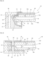
- FIG. 6 presents another embodiment of connection by direct bolting. Identical elements are found and retain the same reference such as the retaining device 52 composed of an outer plate 54 and an inner plate 56 and the spacer 62.
- the difference with the embodiment of the figure 4 consists of the presence of an outer ply 68 not coated in mineral material and the fact of enclosing the inner ply with the coating layer and fixing the glass to the frame by the same fixing means.
- the thickness e"1, e"3 of the coating layer is uniform over the entire surface of each face 40a, 40b of the fold and different from one face to the other, namely that the thickness e" 1 is different from the thickness e"3. They could be of identical thickness.
- the thickness h" of the extension corresponds to the sum of the thickness of the fold h"1 and the thickness e"1, e"3 of the coating layer of the two sides of the fold. In this way it emerges a continuity of thickness of the ice formed by the coated ply at the level of the extension 48.
- the outer ply 68 is fixed to the coating layer of the inner ply 40 using the glue 47 described above.
- the outer fold 68 has a dimension smaller than the inner fold 40 in both longitudinal and lateral directions. It is protected by a seal 70 all along its peripheral edge 71; the seal 70 is provided on the exterior face 46a of the coating layer; it is fixed between the outer plate 54 and the outer fold 68 to ensure sealing.
- a seal 72 is also provided at the level of the inner peripheral edge 73 of the inner plate 56 of the retaining device 52 to prevent water from infiltrating inside the aircraft and avoid pressure losses at the cockpit level.
- the joints 70 and 72 are in one piece. They can be made of silicone.
- the inner 56 and outer 54 plates of the retaining device, the extension 48 and the frame 44 have aligned through holes 49: the assembly is held using a bolt 50 adapted to port 49.
- the ice includes two plies, an inner ply 40 and an outer ply 68. Only the inner ply 40 is coated.
- the outer ply 68 is composed of a mineral material (as in the example of the Figure 6 ).
- the outer fold 68 has a dimension smaller than the inner fold 40 in both longitudinal and lateral directions. It is protected by a seal 70 all along its peripheral edge 71 and retained on the inner fold 40 coated by the glue 47 provided on its interior side.
- the peripheral edge 42 of the coated inner ply 40 is surrounded by a seal 82.
- the joints 70 and 82 are in one piece. They can be made of silicone.
- the peripheral edge 53 of the glass and more precisely the seal 82 is sandwiched, interposed between the frame 44 and a flange 84 whose shape matches that of the frame 44: the shape of the flange 84 also matches the shape of the peripheral edge 53 of the glass surrounded by the seal 82.
- the flange 84 in the example illustrated is fixed on the frame 44 by means of a bolt 86 penetrating into a through hole 88 of the flange and a through hole 90 of the frame 44 aligned so as to block the peripheral edge of the glass between the flange and the frame. The frame and the flange are held together and tightened against each other using bolt 86.
- the frame 44 and the flange 84 forms a clamp in which the inner fold 40 is held, coated by its peripheral edge 42.
- the seals 70 and 82 completely envelop the peripheral edge of the glass so that it is not in direct contact with the frame 44 and the flange 84.
- the flange 84 is made for example of metal, by known machining means.
- the seal 82 encircling the peripheral edge 42 of the window is compressed so as to ensure sealing between the interior and exterior of the aircraft on the entire perimeter of the ice. Additional seals can be provided to reinforce or complete this seal.
- the dimension of the outer fold 68 is such that the fold enveloped in the seal 70 fits into the opening offered by the flange 84.
- the other inner fold 40 projects towards the structure of the aircraft with respect to the outer fold 68.
- the outer fold 68 held by the seal adjoins the free end of the flange 84.
- any other form of fixing the ice comprising one or more folds of coated mineral material to the primary structure is possible.
- the examples provided are only given as an illustration of application to folded ice made of coated mineral material.
Abstract
L'invention vise à proposer une nouvelle architecture de pare-brise à glace présentant au moins un pli en matériau minéral tout en permettant de recourir à un assemblage par boulonnage direct ainsi que l'aéronef pourvu d'un tel pare-brise. Pour ce faire, le pare-brise d'aéronef selon la présente invention comprend une glace (38) comportant au moins un pli (40) de matériau transparent et d'origine minéral et présentant un bord périphérique (42). Au moins un des plis (40) de la glace en matériau minéral est/sont enrobé(s) d'une couche (46) d'enrobage de matériau organique transparent viscoélastique sur l'ensemble de sa/leur surface incluant le bord périphérique.

Description
La présente invention concerne un pare-brise d'aéronef et un aéronef pourvu d'un tel pare-brise. L'invention s'applique à tous les types d'aéronefs munis d'un pare-brise et notamment aux avions civils et militaires ainsi qu'aux hélicoptères.The present invention relates to an aircraft windshield and an aircraft provided with such a windshield. The invention applies to all types of aircraft equipped with a windshield and in particular to civil and military aircraft as well as helicopters.
Dans la plupart des aéronefs, le pare-brise comprend une glace comprenant plusieurs plis de matériaux transparents variés permettant d'offrir des caractéristiques structurales adaptées à la résistance mécanique nécessaire. Les glaces doivent en effet résister aux variations de pression et de température, aux impacts de différentes natures (oiseaux, grêle, rayures, abrasion ...). Les matériaux transparents utilisés peuvent être d'origine minérale (verre, quartz, silice ... ou combinaison de ceux-ci) ou d'origine organique (acrylique, polycarbonate, résines, polymethylmethacrylate appelé plus communément plexiglas (marque déposée), ... ou combinaison de ceux-ci). Les glaces peuvent également comprendre une combinaison de plis d'origine organique et d'un pli d'origine minérale en général du verre positionné le plus à l'extérieur ; l'une de ses faces est donc à l'air libre. Les glaces sont fixées dans une ouverture ménagée dans la structure de la pointe avant de l'aéronef, au niveau du poste de pilotage sur un encadrement adapté faisant partie de la structure de l'aéronef. Les glaces peuvent être pincées au niveau de leur rebord périphérique entre l'encadrement et une bride de serrage assujetties à la structure de l'aéronef à l'aide de fixations de type vis-écrou par exemple ou directement boulonnées au niveau de leur rebord périphérique à l'encadrement.In most aircraft, the windshield includes a glass comprising several plies of varied transparent materials making it possible to offer structural characteristics adapted to the necessary mechanical resistance. The ice must in fact resist variations in pressure and temperature, impacts of different types (birds, hail, scratches, abrasion, etc.). The transparent materials used can be of mineral origin (glass, quartz, silica, etc. or combination of these) or of organic origin (acrylic, polycarbonate, resins, polymethylmethacrylate more commonly called plexiglass (registered trademark), etc. . or combination thereof). The glasses can also include a combination of folds of organic origin and a fold of mineral origin generally of the glass positioned most outside; one of its faces is therefore in the open air. The windows are fixed in an opening made in the structure of the front end of the aircraft, at the level of the cockpit on a suitable frame forming part of the structure of the aircraft. The windows can be pinched at their peripheral edge between the frame and a clamp secured to the structure of the aircraft using screw-nut type fasteners for example or directly bolted at their peripheral edge to supervision.
Selon l'exemple décrit dans le
Les diverses contraintes auxquelles sont soumis les pare-brise impliquent l'utilisation de matériaux déterminés parmi ceux précités. Ainsi une glace présentant des plis structuraux en matériau d'origine organique sera de manière générale fixée à la structure de l'aéronef par un principe de boulonnage direct, la souplesse des matériaux le permettant. Une glace présentant des plis structuraux en matériau d'origine minérale sera de préférence fixée à la structure suivant un principe d'assemblage par bride du type de celui décrit ci-dessus dans le brevet mentionné permettant la fixation par boulon en dehors des plis sans les traverser.The various constraints to which windshields are subject imply the use of materials determined among those mentioned above. Thus, a glass having structural folds made of material of organic origin will generally be fixed to the structure of the aircraft by a direct bolting principle, the flexibility of the materials allowing it. A glass having structural folds made of material of mineral origin will preferably be fixed to the structure following a flange assembly principle of the type described above in the patent mentioned allowing fixing by bolt outside the folds without them. to cross.
La présente invention vise à proposer une nouvelle architecture de pare-brise à glace présentant au moins un pli en matériau minéral interne permettant de pallier tous les inconvénients précités et permettant notamment de choisir plus librement le type d'assemblage.The present invention aims to propose a new ice windshield architecture having at least one fold of internal mineral material making it possible to overcome all of the aforementioned drawbacks and in particular making it possible to choose the type of assembly more freely.
A cet effet, la présente invention concerne un pare-brise d'aéronef comprenant une glace comportant au moins un pli de matériau transparent et d'origine minéral et présentant un bord périphérique, caractérisé en ce qu'au moins un des plis de la glace en matériau minéral est/sont enrobé(s) d'une couche d'enrobage de matériau organique transparent viscoélastique sur l'ensemble de sa/leur surface incluant le bord périphérique.For this purpose, the present invention relates to an aircraft windshield comprising a glass comprising at least one fold of transparent material of mineral origin and having a peripheral edge, characterized in that at least one of the folds of the glass made of mineral material is/are coated with a coating layer of viscoelastic transparent organic material over its entire surface including the peripheral edge.
L'enrobage de plis en matériau minéral d'une glace par une couche de matière viscoélastique permet de les protéger en renforçant leur solidité. Par ailleurs la couche d'enrobage est utilisée pour améliorer l'étanchéité et faciliter l'assemblage du pare-brise sur la structure avion en permettant par exemple une fixation par boulonnage direct malgré l'utilisation de plis en matériau minéral.The coating of folds of mineral material in a glass with a layer of viscoelastic material allows them to be protected by reinforcing their solidity. Furthermore, the coating layer is used to improve the seal and facilitate the assembly of the windshield on the aircraft structure by allowing, for example, fixing by direct bolting despite the use of layers of mineral material.
L'invention prévoit au moins l'une des caractéristiques optionnelles suivantes, prises isolément ou en combinaison.The invention provides at least one of the following optional characteristics, taken individually or in combination.
Chacun des plis en matériau minéral de la glace est enrobé.Each of the layers of mineral material in the ice is coated.
Un pli externe en matériau minéral non enrobé est prévu dont la face extérieure est la face la plus à l'extérieur de la glace et la face interne est accolée à la face extérieure de la couche d'enrobage la plus à l'extérieur par l'intermédiaire d'une colle et en ce que chacun des plis interne est enrobé.An outer ply of uncoated mineral material is provided, the outer face of which is the outermost face of the ice and the inner face is adjoined to the outer face of the outermost coating layer by the via a glue and in that each of the internal folds is coated.
La couche d'enrobage forme une enveloppe monobloc.The coating layer forms a one-piece envelope.
La couche d'enrobage est en matériau Opticor (marque déposée).The coating layer is made of Opticor material (registered trademark).
La couche d'enrobage comprend une extension au niveau de la totalité du bord périphérique du pli qui présente une ouverture traversante.The coating layer includes an extension at the entire peripheral edge of the ply which has a through opening.
Le matériau minéral est du verre.The mineral material is glass.
La présente invention concerne également un aéronef comprenant un encadrement faisant partie de la structure primaire de l'aéronef et un pare-brise associé audit encadrement présentant une ou plusieurs des caractéristiques précitées.The present invention also relates to an aircraft comprising a frame forming part of the primary structure of the aircraft and a windshield associated with said frame having one or more of the aforementioned characteristics.
Selon une première forme de réalisation, le ou les plis enrobés et la couche d'enrobage sont maintenus à l'aide d'une fixation par bride.According to a first embodiment, the coated fold(s) and the coating layer are held using a flange fixing.
Selon une deuxième forme de réalisation, des moyens de fixation de type vis-écrou traversent l'extension par l'ouverture pour enserrer la couche d'enrobage et le ou les plis enrobés.According to a second embodiment, screw-nut type fixing means pass through the extension through the opening to enclose the coating layer and the coated fold(s).
D'autres buts, caractéristiques et avantages ressortiront de la description de l'invention qui va suivre, description donnée à titre d'exemple uniquement non limitatif, en référence aux dessins ci-annexés dans lesquels :
- [
Fig. 1 ] est une vue en en plan en coupe transversal d'un pare-brise selon l'art antérieur ; - [
Fig. 2 ] est une vue en perspective d'un aéronef muni d'un pare-brise selon la présente invention ; - [
Fig. 3 ] est une vue en perspective éclatée d'une glace d'un pare-brise et d'un encadrement d'aéronef selon la présente invention ; - [
Fig. 4 ] est une vue en plan en coupe transversale selon un plan tel que le plan X-X représenté sur lafigure 3 d'une première forme de réalisation d'un pare-brise selon la présente invention ; - [
Fig. 5 ] est une vue en plan en coupe transversale selon un plan tel que le plan X-X représenté sur lafigure 3 d'une deuxième forme de réalisation d'un pare-brise selon la présente invention ; - [
Fig. 6 ] est une vue en plan en coupe transversale selon un plan tel que le plan X-X représenté sur lafigure 3 d'une troisième forme de réalisation d'un pare-brise selon la présente invention.
- [
Fig. 1 ] is a transverse sectional plan view of a windshield according to the prior art; - [
Fig. 2 ] is a perspective view of an aircraft equipped with a windshield according to the present invention; - [
Fig. 3 ] is an exploded perspective view of a glass of a windshield and an aircraft frame according to the present invention; - [
Fig. 4 ] is a plan view in cross section along a plane such as plane XX shown on theFigure 3 a first embodiment of a windshield according to the present invention; - [
Fig. 5 ] is a plan view in cross section along a plane such as plane XX shown on theFigure 3 a second embodiment of a windshield according to the present invention; - [
Fig. 6 ] is a plan view in cross section along a plane such as plane XX shown on theFigure 3 of a third embodiment of a windshield according to the present invention.
La
Selon la présente invention, comme montré dans l'ensemble des formes de réalisation données uniquement à titre illustratif sur les
Lorsqu'un assemblage par boulonnage direct est utilisé pour fixer la glace 38 à l'encadrement 44 comme sur les
Dans l'exemple de la
La
Selon une autre forme de réalisation de fixation par bride représentée sur la
Toute autre forme de fixation de la glace comprenant un ou plusieurs plis en matériau minéral enrobé, à la structure primaire est possible. Les exemples apportés ne sont donnés qu'à titre illustratif d'application à la glace à pli en matériau minéral enrobé.Any other form of fixing the ice comprising one or more folds of coated mineral material to the primary structure is possible. The examples provided are only given as an illustration of application to folded ice made of coated mineral material.
Claims (10)
Applications Claiming Priority (1)
| Application Number | Priority Date | Filing Date | Title |
|---|---|---|---|
| FR2204031A FR3135060A1 (en) | 2022-04-28 | 2022-04-28 | NEW WINDSHIELD ARCHITECTURE AND AIRCRAFT EQUIPPED WITH SUCH A WINDSHIELD |
Publications (1)
| Publication Number | Publication Date |
|---|---|
| EP4269230A1 true EP4269230A1 (en) | 2023-11-01 |
Family
ID=83506178
Family Applications (1)
| Application Number | Title | Priority Date | Filing Date |
|---|---|---|---|
| EP23170263.0A Pending EP4269230A1 (en) | 2022-04-28 | 2023-04-27 | Novel windscreen architecture and aircraft provided with such a windscreen |
Country Status (4)
| Country | Link |
|---|---|
| US (1) | US20230348037A1 (en) |
| EP (1) | EP4269230A1 (en) |
| CN (1) | CN116968915A (en) |
| FR (1) | FR3135060A1 (en) |
Citations (3)
| Publication number | Priority date | Publication date | Assignee | Title |
|---|---|---|---|---|
| FR2830236A1 (en) | 2001-10-02 | 2003-04-04 | Airbus France | DEVICE FOR FIXING AN AIRCRAFT WINDSHIELD |
| US8033505B2 (en) * | 2007-04-18 | 2011-10-11 | Airbus Deutschland Gmbh | Aircraft door window |
| US20200298952A1 (en) * | 2019-03-22 | 2020-09-24 | Bombardier Inc. | Optically enhanced aircraft window |
-
2022
- 2022-04-28 FR FR2204031A patent/FR3135060A1/en active Pending
-
2023
- 2023-04-26 US US18/307,243 patent/US20230348037A1/en active Pending
- 2023-04-27 CN CN202310473429.1A patent/CN116968915A/en active Pending
- 2023-04-27 EP EP23170263.0A patent/EP4269230A1/en active Pending
Patent Citations (3)
| Publication number | Priority date | Publication date | Assignee | Title |
|---|---|---|---|---|
| FR2830236A1 (en) | 2001-10-02 | 2003-04-04 | Airbus France | DEVICE FOR FIXING AN AIRCRAFT WINDSHIELD |
| US8033505B2 (en) * | 2007-04-18 | 2011-10-11 | Airbus Deutschland Gmbh | Aircraft door window |
| US20200298952A1 (en) * | 2019-03-22 | 2020-09-24 | Bombardier Inc. | Optically enhanced aircraft window |
Also Published As
| Publication number | Publication date |
|---|---|
| FR3135060A1 (en) | 2023-11-03 |
| US20230348037A1 (en) | 2023-11-02 |
| CN116968915A (en) | 2023-10-31 |
Similar Documents
| Publication | Publication Date | Title |
|---|---|---|
| EP1824696B1 (en) | Complex partition glass consisting of at least two adjacent glass elements, and method for producing said complex partition glass | |
| EP2106364B1 (en) | Section of aircraft fuselage and aircraft including one such section | |
| EP0962741B1 (en) | Device for provisionally connecting and pyrotechnically separating two non-metallic units | |
| EP2000382A1 (en) | Train driver cabin with a glazing | |
| FR3089947A1 (en) | transparent fuselage element of an aircraft intended to seal a bay of said aircraft | |
| FR2939104A1 (en) | AIRCRAFT WITH INTERNCHANGEABLE WINDSHIELD GLAZES BETWEEN DIFFERENT TYPES | |
| EP2121362B1 (en) | Method for assembling a glazing on its holder by gluing, and means for realising said method | |
| EP0893340B1 (en) | Kit for mounting a sliding laminated glazing in an aircraft cockpit | |
| FR3003233A1 (en) | PANEL FOR AIRCRAFT FOR AIRCRAFT | |
| EP4269230A1 (en) | Novel windscreen architecture and aircraft provided with such a windscreen | |
| WO2006077296A1 (en) | Panoramic windscreen for a motor vehicle | |
| FR2684051A1 (en) | Sealing device for transparent panels fitting flush on a vehicle bodywork | |
| WO2019115931A1 (en) | Glazing unit, in particular for aeronautics, able to be blocked in its receiving opening in the event of breakage | |
| EP3476717B1 (en) | Aircraft windscreen with integrated flange and load distribution inserts | |
| FR3039128A1 (en) | GLAZING WITH INTEGRATED STRUCTURAL FRAMEWORK FOR AIRCRAFT | |
| FR3072937B1 (en) | LARGE VEHICLE WINDOW AND VEHICLE. | |
| EP0352151B1 (en) | Mobile transparent panel, particularly a transparent panel of a vehicle tailgate | |
| FR3121068A1 (en) | GLAZING COMPRISING TWO GLAZES AND AN ASSEMBLY GASKET FOR SAID GLAZES | |
| WO2024056879A1 (en) | Glazed system configured to block glazing rotations | |
| EP3885510B1 (en) | Attachment bracket for a construction assembly | |
| WO2024056878A1 (en) | Glazed system configured to prevent glass panels from slipping | |
| EP0233821B1 (en) | Glass pane | |
| FR3113093A1 (en) | PROPULSION SYSTEM OF AN AIRCRAFT COMPRISING AN IMPROVED SEALING SYSTEM | |
| FR3132502A1 (en) | Glazed assembly for an aircraft, method of manufacturing such a glazed assembly, and aircraft comprising such a glazed assembly | |
| FR3085882A1 (en) | SHEET GLAZING WITH INTEGRATED FUNCTIONAL ELEMENT |
Legal Events
| Date | Code | Title | Description |
|---|---|---|---|
| PUAI | Public reference made under article 153(3) epc to a published international application that has entered the european phase |
Free format text: ORIGINAL CODE: 0009012 |
|
| STAA | Information on the status of an ep patent application or granted ep patent |
Free format text: STATUS: THE APPLICATION HAS BEEN PUBLISHED |
|
| AK | Designated contracting states |
Kind code of ref document: A1 Designated state(s): AL AT BE BG CH CY CZ DE DK EE ES FI FR GB GR HR HU IE IS IT LI LT LU LV MC ME MK MT NL NO PL PT RO RS SE SI SK SM TR |