EP2106364B1 - Section of aircraft fuselage and aircraft including one such section - Google Patents
Section of aircraft fuselage and aircraft including one such section Download PDFInfo
- Publication number
- EP2106364B1 EP2106364B1 EP08750462A EP08750462A EP2106364B1 EP 2106364 B1 EP2106364 B1 EP 2106364B1 EP 08750462 A EP08750462 A EP 08750462A EP 08750462 A EP08750462 A EP 08750462A EP 2106364 B1 EP2106364 B1 EP 2106364B1
- Authority
- EP
- European Patent Office
- Prior art keywords
- section
- fuselage
- frame
- frame segment
- aircraft
- Prior art date
- Legal status (The legal status is an assumption and is not a legal conclusion. Google has not performed a legal analysis and makes no representation as to the accuracy of the status listed.)
- Active
Links
- 239000002131 composite material Substances 0.000 claims abstract description 11
- 230000006641 stabilisation Effects 0.000 claims 1
- 229920000049 Carbon (fiber) Polymers 0.000 abstract description 3
- 239000004917 carbon fiber Substances 0.000 abstract description 3
- VNWKTOKETHGBQD-UHFFFAOYSA-N methane Chemical compound C VNWKTOKETHGBQD-UHFFFAOYSA-N 0.000 abstract description 2
- 229920005989 resin Polymers 0.000 abstract description 2
- 239000011347 resin Substances 0.000 abstract description 2
- 210000000056 organ Anatomy 0.000 description 4
- 230000000087 stabilizing effect Effects 0.000 description 4
- 238000010276 construction Methods 0.000 description 3
- 238000005260 corrosion Methods 0.000 description 2
- 230000007797 corrosion Effects 0.000 description 2
- 238000002347 injection Methods 0.000 description 2
- 239000007924 injection Substances 0.000 description 2
- 229910000838 Al alloy Inorganic materials 0.000 description 1
- RTAQQCXQSZGOHL-UHFFFAOYSA-N Titanium Chemical compound [Ti] RTAQQCXQSZGOHL-UHFFFAOYSA-N 0.000 description 1
- 230000002411 adverse Effects 0.000 description 1
- 238000004378 air conditioning Methods 0.000 description 1
- 239000004035 construction material Substances 0.000 description 1
- 229920001971 elastomer Polymers 0.000 description 1
- 239000000806 elastomer Substances 0.000 description 1
- 229940082150 encore Drugs 0.000 description 1
- 239000000835 fiber Substances 0.000 description 1
- 230000005484 gravity Effects 0.000 description 1
- 230000003100 immobilizing effect Effects 0.000 description 1
- 229910001026 inconel Inorganic materials 0.000 description 1
- 238000009413 insulation Methods 0.000 description 1
- 239000003350 kerosene Substances 0.000 description 1
- 238000012423 maintenance Methods 0.000 description 1
- 238000000034 method Methods 0.000 description 1
- 238000011084 recovery Methods 0.000 description 1
- 230000002787 reinforcement Effects 0.000 description 1
- 238000004088 simulation Methods 0.000 description 1
- 229920001169 thermoplastic Polymers 0.000 description 1
- 239000004416 thermosoftening plastic Substances 0.000 description 1
- 229910052719 titanium Inorganic materials 0.000 description 1
- 239000010936 titanium Substances 0.000 description 1
Images


Classifications
-
- B—PERFORMING OPERATIONS; TRANSPORTING
- B64—AIRCRAFT; AVIATION; COSMONAUTICS
- B64C—AEROPLANES; HELICOPTERS
- B64C1/00—Fuselages; Constructional features common to fuselages, wings, stabilising surfaces or the like
- B64C1/06—Frames; Stringers; Longerons ; Fuselage sections
- B64C1/12—Construction or attachment of skin panels
-
- B—PERFORMING OPERATIONS; TRANSPORTING
- B64—AIRCRAFT; AVIATION; COSMONAUTICS
- B64C—AEROPLANES; HELICOPTERS
- B64C1/00—Fuselages; Constructional features common to fuselages, wings, stabilising surfaces or the like
- B64C1/06—Frames; Stringers; Longerons ; Fuselage sections
- B64C1/061—Frames
-
- B—PERFORMING OPERATIONS; TRANSPORTING
- B64—AIRCRAFT; AVIATION; COSMONAUTICS
- B64C—AEROPLANES; HELICOPTERS
- B64C1/00—Fuselages; Constructional features common to fuselages, wings, stabilising surfaces or the like
- B64C1/06—Frames; Stringers; Longerons ; Fuselage sections
- B64C1/068—Fuselage sections
-
- B—PERFORMING OPERATIONS; TRANSPORTING
- B64—AIRCRAFT; AVIATION; COSMONAUTICS
- B64C—AEROPLANES; HELICOPTERS
- B64C1/00—Fuselages; Constructional features common to fuselages, wings, stabilising surfaces or the like
- B64C1/14—Windows; Doors; Hatch covers or access panels; Surrounding frame structures; Canopies; Windscreens accessories therefor, e.g. pressure sensors, water deflectors, hinges, seals, handles, latches, windscreen wipers
Definitions
- the present invention relates to a fuselage section for an aircraft and an aircraft comprising such a section.
- openings are made in the side walls of the fuselage to accommodate portholes and allow passengers to see the outside environment directly to the fuselage.
- an aircraft window must provide thermal and sound insulation of the fuselage interior space from the outside to ensure passenger comfort. It must likewise be airtight and watertight.
- the frame of the window which is typically riveted to the skin of the fuselage, must also withstand mechanical stresses such as the loads due to the flexion of the fuselage and the pressurization that is applied to the porthole.
- the porthole must finally respect the aerodynamic profile of the aircraft.
- shear forces 4 related to the flexion of the fuselage and pressurizing forces 5 which act transversely and longitudinally to the fuselage section.
- the assembly of the portholes 1 in the openings of the side wall of the fuselage section is achieved using mechanical fasteners.
- these specific reinforcements of the fuselage wall also represent an additional weight which adversely affects the kerosene consumption of the aircraft.
- the objective of the present invention is therefore to propose an aircraft fuselage section that is simple in its design and in its operating mode, having a very high mechanical strength for the construction of an aircraft, while at the same time making it possible to reduce the mass of the aircraft. fuselage structure of this aircraft.
- Another object of the present invention is a fuselage section comprising portholes having dimensions greater than those encountered in the state of the art.
- the invention relates to an aircraft fuselage section comprising frames and openings for receiving portholes.
- At least some of these frames each comprise at least one frame sector surrounding at least one opening, this frame sector comprising two branches disposed laterally to the opening, the ends of said branches being coupled so as to form a Y at each end of this frame area.
- This stabilizing veil defines a housing between two frame sectors capable of receiving one or more elongate elements such as cables or air conditioning pipes.
- the present invention is applicable to any type of aircraft fuselage known.
- the side wall of a fuselage section for a double-deck airplane comprises for each bridge a row of openings intended to receive portholes, and frames. At least some of these frames each have two frame sectors, i.e. a frame sector by porthole and bridge.
- the fuselage section of the present invention is particularly suitable for an aircraft fuselage in which the width of the windows is substantially as large as, or even greater than, the distance separating two successive frames of the fuselage.
- a frame sector can surround a window in one piece or having several parts. In the latter case, these parts are then spaced by one or more sleepers.
- a cross member may divide a field of view into two openings having a triangular, semicircular, or other shape.
- the invention relates to an aircraft having a fuselage whose side walls comprise portholes.
- the fuselage comprises at least one fuselage section as described above.
- the transverse dimension of the windows of said aircraft is greater than or equal to the distance separating two successive frames of the fuselage.
- the Figure 3 shows an aircraft fuselage section according to a particular embodiment of the invention.
- the fuselage section may be a composite fuselage section.
- this fuselage section can be made based on carbon fibers.
- the fuselage section has frames 10 and portholes 11 mounted on openings. These portholes 11 are aligned and evenly spaced along the longitudinal axis 12 of the fuselage section.
- Each frame 10 comprises two frame portions 13, 14 interconnected by a frame sector surrounding a window 11.
- the frame sector is secured to these frame portions 13, 14 by fasteners.
- fasteners include, for example, splints which connect the frame sectors to the frames of the flag and the boat thus conferring a certain flexibility in the positioning.
- These splints can be metallic or composite. As an illustration, they are made of titanium, inconel or aluminum alloy when they are metallic. It can be alternatively thermoplastic composites.
- the door 11 comprises in known manner an external transparent element, at least one internal transparent element and a window frame.
- the inner transparent element of this porthole preferably has an elliptical shape.
- the dimensions of the inner transparent element of the window are of the order of 520 x 299 mm thus providing a larger field of view for the passenger than the windows known from the prior art.
- the window 11 may have any other shape chosen from the group comprising a triangular shape, circular, rectangular, or other.
- Each frame sector comprises two branches 15, 16 disposed laterally to the window 11 and whose ends are coupled to form a Y at each of the ends 17, 18 of the frame sector.
- the branches 15, 16 have in their central part a curved shape so that the frame sector has a substantially elliptical shape.
- Each window 11 is substantially centered on its corresponding frame sector, a space separating the lateral branches 15, 16 of the frame sector from the periphery of the window 11.
- the stiffening elements of the fuselage section further comprise frames 10, smooth 19.
- the fuselage section comprises a rail 19 placed between the window 11 and each end 17, 18 of the frame sector. This rail 19 arranged tangentially to the window 11 allows to border at its upper and lower ends the opening of the side wall of the fuselage receiving the window 11.
- the off-plane stiffening of the fuselage section of the invention is thus reduced at least.
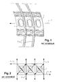
- the Figure 4 schematically shows the result of a simulation of the stresses on the fuselage section at the portholes 11.
- the frame sectors of the invention advantageously drain the flow related to the pressurization Y around the portholes.
- the portholes 11 are thus no longer subjected directly to the constraints resulting from the pressurization contrary to the state of the art.
- the passage of the constraints of the lower zone towards the upper zone of the fuselage section makes it possible to increase the size of the portholes.
- the frame sectors are oriented along the diagonal of the inter-porthole mesh which allows the frame sectors to resume the shear of the window strip (vertical burst case).
- a stabilizing veil 20 is placed between two successive frame supports in the longitudinal direction 12 of the fuselage section. These sails 20 make it possible to stabilize the frame sectors and to resume the opening efforts.
- the Figure 6 shows a partial sectional view along the axis AA of the fuselage section of the Figure 5 .
- Elements bearing the same references as the elements of the Figure 3 represent the same objects, which will not be described again below.
- the side wall 21 of the fuselage section comprises an opening on which a window 11 is mounted.
- This window 11 comprises an external transparent element 22 and at least one internal transparent element (not shown).
- a flexible gasket makes it possible to assemble the external transparent element 22 and the internal transparent element while keeping them separated one and the other by an interspace.
- This seal is, for example, made of elastomer.
- the side wall 21 of the fuselage section has a chamfer 24 along the periphery of the opening, this chamfer 24 having a shape substantially similar to that of an edge of the outer transparent member 22 so as to lock laterally and longitudinally the outer transparent element 22 in this opening.
- the outermost surface of the transparent element 22 has a shape providing aerodynamic continuity with the sidewall of the fuselage of the aircraft.
- the door 11 is fixed conventionally on the opening by means of a retaining clip 23 which is mounted on the frame of the window 11 by means of nuts and studs.
Abstract
Description
La présente invention concerne une section de fuselage pour aéronef et un aéronef comportant une telle section.The present invention relates to a fuselage section for an aircraft and an aircraft comprising such a section.
Il est connu que les avions commerciaux comportent un fuselage typiquement pseudo-cylindrique renforcé par des éléments raidisseurs tels que des lisses et des cadres de manière à résister aux contraintes mécaniques qui s'exercent en vol par exemple.It is known that commercial aircraft have a typically pseudo-cylindrical fuselage reinforced by stiffening elements such as rails and frames so as to withstand the mechanical stresses in flight for example.
Dans les avions commerciaux par exemple, des ouvertures sont réalisées dans les parois latérales du fuselage pour accueillir des hublots et permettre aux passagers de voir directement l'environnement extérieur au fuselage.In commercial aircraft for example, openings are made in the side walls of the fuselage to accommodate portholes and allow passengers to see the outside environment directly to the fuselage.
Toutefois, ces hublots génèrent de nombreux inconvénients. Tout d'abord, un hublot d'avion doit assurer une isolation thermique et phonétique de l'espace intérieur du fuselage de l'extérieur afin d'assurer le confort des passagers. Il doit pareillement être étanche à l'air et à l'eau.However, these portholes generate many disadvantages. First, an aircraft window must provide thermal and sound insulation of the fuselage interior space from the outside to ensure passenger comfort. It must likewise be airtight and watertight.
L'encadrement du hublot qui est typiquement riveté à la peau du fuselage, doit également résister aux contraintes mécaniques telles que les charges dues à la flexion du fuselage et la pressurisation qui est appliquée au hublot.The frame of the window which is typically riveted to the skin of the fuselage, must also withstand mechanical stresses such as the loads due to the flexion of the fuselage and the pressurization that is applied to the porthole.
Le hublot doit enfin respecter le profil aérodynamique de l'avion.The porthole must finally respect the aerodynamic profile of the aircraft.
Toutes ces contraintes ont conduit les constructeurs à un raidissement spécifique de la zone hublot.
- La
Figure 1 est une vue partielle d'une section de fuselage d'un avion de l'art antérieur. Cette section comporte deshublots 1 qui sont espacés régulièrement en étant alignés le long d'un axe longitudinal 2 de la section de fuselage. Elle comporte également descadres 3, encore appelés couples, qui permettent de renforcer mécaniquement la section de fuselage et de donner la forme de sa paroi. Le pas des cadres, c'est-à-dire la distance séparant deuxcadres 3 successifs, est supérieur à la largeur deshublots 1. L'art antérieur est également illustré par le documentUS 2006/0060705 - La
Figure 2 montre schématiquement les contraintes mécaniques auxquelles ceshublots 1 peuvent être soumis.
- The
Figure 1 is a partial view of a fuselage section of a plane of the prior art. This section comprisesportholes 1 which are regularly spaced by being aligned along alongitudinal axis 2 of the fuselage section. It also includesframes 3, also called couples, which can mechanically strengthen the fuselage section and give the shape of its wall. The pitch of the frames, that is to say the distance separating twosuccessive frames 3, is greater than the width of theportholes 1. The prior art is also illustrated by the documentUS 2006/0060705 - The
Figure 2 schematically shows the mechanical stresses to which theseportholes 1 can be subjected.
Ces contraintes mécaniques sont de deux types. Il s'agit de forces de cisaillement 4 liées à la flexion du fuselage et de forces de pressurisation 5 qui agissent transversalement et longitudinalement à la section de fuselage.These mechanical constraints are of two types. These are shear forces 4 related to the flexion of the fuselage and pressurizing
Toutes ces contraintes ont conduit les constructeurs à un raidissement spécifique de la zone hublot 1 avec des surépaisseurs de la paroi de fuselage au niveau de l'ouverture de hublot 1 et un encadrement pour garantir la tenue mécanique du hublot.All these constraints led the manufacturers to a specific stiffening of the
L'assemblage des hublots 1 dans les ouvertures de la paroi latérale de la section de fuselage est réalisé à l'aide de fixations mécaniques.The assembly of the
Toutefois, cet assemblage représente une tâche difficile pour les opérateurs et est consommateur de temps. Cet assemblage est donc coûteux en immobilisation de l'avion en cas de maintenance.However, this assembly represents a difficult task for operators and is time consuming. This assembly is therefore expensive in immobilizing the aircraft in case of maintenance.
Par ailleurs, ces renforcements spécifiques de la paroi de fuselage représentent également un poids supplémentaire qui affecte de manière négative la consommation en kérosène de l'avion.In addition, these specific reinforcements of the fuselage wall also represent an additional weight which adversely affects the kerosene consumption of the aircraft.
Il existe donc un besoin important pour réduire la masse spécifique du fuselage de l'avion tout en garantissant la tenue mécanique de la paroi du fuselage au niveau des hublots.There is therefore an important need to reduce the specific gravity of the fuselage of the aircraft while ensuring the mechanical strength of the wall of the fuselage at the portholes.
L'objectif de la présente invention est donc de proposer une section de fuselage pour aéronef simple dans sa conception et dans son mode opératoire, présentant une résistance mécanique très importante pour la construction d'un aéronef, tout en permettant de réduire la masse de la structure fuselage de cet aéronef.The objective of the present invention is therefore to propose an aircraft fuselage section that is simple in its design and in its operating mode, having a very high mechanical strength for the construction of an aircraft, while at the same time making it possible to reduce the mass of the aircraft. fuselage structure of this aircraft.
Cette réduction de masse de la structure fuselage est d'autant plus importante que le motif de la maille hublot se répète de n'ombreuses fois sur ce dernier.This reduction in mass of the fuselage structure is all the more important that the pattern of the window mesh is repeated many times on the latter.
Un autre objet de la présente invention est une section de fuselage comprenant des hublots présentant des dimensions supérieures à celles rencontrées dans l'état de l'art.Another object of the present invention is a fuselage section comprising portholes having dimensions greater than those encountered in the state of the art.
A cet effet, l'invention concerne une section de fuselage pour aéronef comportant des cadres et des ouvertures pour recevoir des hublots.For this purpose, the invention relates to an aircraft fuselage section comprising frames and openings for receiving portholes.
Selon l'invention, au moins certains de ces cadres comportent chacun au moins un secteur de cadre entourant au moins une ouverture, ce secteur de cadre comprenant deux branches disposées latéralement à l'ouverture, les extrémités desdites branches étant accouplées de manière à former un Y à chacune des extrémités de ce secteur de cadre.According to the invention, at least some of these frames each comprise at least one frame sector surrounding at least one opening, this frame sector comprising two branches disposed laterally to the opening, the ends of said branches being coupled so as to form a Y at each end of this frame area.
Deux supports de cadre successifs dans le sens longitudinal de la section de fuselage sont reliés entre eux par un voile de stabilisation.
Ce voile de stabilisation permet de définir un logement entre deux secteurs de cadre susceptible de recevoir un ou plusieurs éléments allongés tels que des câbles ou des tuyaux de conditionnement d'air.Two successive frame supports in the longitudinal direction of the fuselage section are interconnected by a stabilizing veil.
This stabilizing veil defines a housing between two frame sectors capable of receiving one or more elongate elements such as cables or air conditioning pipes.
Avantageusement, la présente invention est applicable à tout type de fuselage d'aéronef connu. A titre purement illustratif, la paroi latérale d'une section de fuselage pour avion à double pont, comprend pour chaque pont une rangée d'ouvertures destinées à recevoir des hublots, et des cadres. Au moins certains de ces cadres comportent chacun deux secteurs de cadre, i.e. un secteur de cadre par hublot et par pont.Advantageously, the present invention is applicable to any type of aircraft fuselage known. By way of illustration only, the side wall of a fuselage section for a double-deck airplane comprises for each bridge a row of openings intended to receive portholes, and frames. At least some of these frames each have two frame sectors, i.e. a frame sector by porthole and bridge.
La section de fuselage de la présente invention est particulièrement adaptée à un fuselage d'aéronef dans lequel la largeur des hublots est sensiblement aussi grande que, voire supérieure à, la distance séparant deux cadres successifs du fuselage.The fuselage section of the present invention is particularly suitable for an aircraft fuselage in which the width of the windows is substantially as large as, or even greater than, the distance separating two successive frames of the fuselage.
Par ailleurs, un secteur de cadre peut entourer un hublot d'un seul tenant ou ayant plusieurs parties. Dans ce dernier cas, ces parties sont alors espacées par une ou plusieurs traverses. A titre illustratif, une traverse peut diviser un champ de vision en deux ouvertures ayant une forme triangulaire, semi-circulaire, ou autre.In addition, a frame sector can surround a window in one piece or having several parts. In the latter case, these parts are then spaced by one or more sleepers. As an illustration, a cross member may divide a field of view into two openings having a triangular, semicircular, or other shape.
Dans différents modes de réalisation particuliers de cette section de fuselage, chacun ayant ses avantages particuliers et susceptibles de nombreuses combinaisons techniques possibles:
- les branches du secteur de cadre forment un logement pour recevoir des moyens pour la fixation d'un hublot sur ladite ouverture,
- le secteur de cadre comprenant un hublot fixé à ladite ouverture par des moyens pour la fixation d'un hublot comprenant un clip de maintien, au moins une partie du pourtour de ce clip de maintien a une forme coopérant avec les branches du secteur de cadre pour la reprise d'efforts,
- ledit cadre comportant au moins deux portions de cadre, cette section de fuselage comprend des organes de fixation de ce secteur de cadre sur ces portions de cadre,
- ces organes de fixation comprennent des éclisses,
- le secteur de cadre est d'une construction en une seule pièce et en matériau composite,
Il s'agit, par exemple, d'un matériau composite à base de fibre de carbone et de résine, fabriqué au moyen d'un procédé d'injection ou d'estampage.
- ladite section de fuselage comporte une lisse placée entre l'ouverture et au moins une extrémité du secteur de cadre,
- the branches of the frame sector form a housing for receiving means for fixing a porthole on said opening,
- the frame sector comprising a window fixed to said opening by means for fixing a window comprising a holding clip, at least a portion of the periphery of this holding clip has a shape cooperating with the branches of the frame sector for the recovery of efforts,
- said frame comprising at least two frame portions, this fuselage section comprises fasteners of this frame sector on these frame portions,
- these fixing members comprise splints,
- the frame sector is of a one-piece construction and composite material,
This is, for example, a composite material based on carbon fiber and resin, manufactured by means of an injection or stamping process.
- said fuselage section has a rail placed between the opening and at least one end of the frame sector,
Enfin, l'invention concerne un aéronef ayant un fuselage dont les parois latérales comportent des hublots.Finally, the invention relates to an aircraft having a fuselage whose side walls comprise portholes.
Selon l'invention, le fuselage comprend au moins une section de fuselage telle que décrite précédemment.According to the invention, the fuselage comprises at least one fuselage section as described above.
Avantageusement, la dimension transversale des hublots dudit aéronef est supérieure ou égale à la distance séparant deux cadres successifs du fuselage.Advantageously, the transverse dimension of the windows of said aircraft is greater than or equal to the distance separating two successive frames of the fuselage.
L'invention sera décrite plus en détail en référence aux dessins annexés dans lesquels:
- la
figure 1 représente schématiquement une vue partielle d'une section de fuselage d'un avion de l'art antérieur; - la
figure 2 est une représentation schématique des contraintes mécaniques pouvant s'exercer en vol sur les hublots de la section de fuselage de laFigure 1 ; - la
figure 3 est une vue en perspective d'une section de fuselage pour aéronef selon un mode de réalisation particulier de l'invention; - la
figure 4 est une représentation schématique des contraintes mécaniques pouvant s'exercer sur les hublots de la section de fuselage de laFigure 3 ; - la
figure 5 représente schématiquement la section de fuselage de lafigure 3 en vue de face; - la
figure 6 est une vue en coupe selon l'axe A-A de la section de fuselage de lafigure 5 ;
- the
figure 1 schematically represents a partial view of a fuselage section of a plane of the prior art; - the
figure 2 is a schematic representation of the mechanical stresses that can be exerted in flight on the portholes of the fuselage section of theFigure 1 ; - the
figure 3 is a perspective view of an aircraft fuselage section according to a particular embodiment of the invention; - the
figure 4 is a schematic representation of the mechanical stresses that can be exerted on the portholes of the fuselage section of theFigure 3 ; - the
figure 5 schematically represents the fuselage section of thefigure 3 in front view; - the
figure 6 is a sectional view along the axis AA of the fuselage section of thefigure 5 ;
La
La section de fuselage comporte des cadres 10 et des hublots 11 montés sur des ouvertures. Ces hublots 11 sont alignés et régulièrement espacés le long de l'axe longitudinal 12 de la section de fuselage.The fuselage section has
Chaque cadre 10 comporte deux portions de cadre 13, 14 reliées entre elles par un secteur de cadre entourant un hublots 11. Le secteur de cadre est solidarisé à ces portions de cadre 13, 14 par des organes de fixation. Ces derniers comprennent par exemple des éclisses qui assurent la connexion des secteurs de cadre aux cadres du pavillon et de la barque conférant ainsi une certaine souplesse dans le positionnement.Each
Ces éclisses peuvent être métalliques ou composites. A titre illustratif, elles sont en titane, en inconel ou en alliage d'aluminium lorsqu'elles sont métalliques. Il peut s'agir alternativement de composites thermoplastiques.These splints can be metallic or composite. As an illustration, they are made of titanium, inconel or aluminum alloy when they are metallic. It can be alternatively thermoplastic composites.
Le hublot 11 comporte de manière connue un élément transparent externe, au moins un élément transparent interne et un encadrement de hublot.The
L'élément transparent interne de ce hublot présente, de préférence, une forme elliptique. Avantageusement, les dimensions de l'élément transparent interne du hublot sont de l'ordre de 520 x 299 mm offrant ainsi un champ de vision plus important pour le passager que les hublots connus de l'art antérieur.The inner transparent element of this porthole preferably has an elliptical shape. Advantageously, the dimensions of the inner transparent element of the window are of the order of 520 x 299 mm thus providing a larger field of view for the passenger than the windows known from the prior art.
Bien entendu, le hublot 11 peut avoir tout autre forme choisie dans le groupe comprenant une forme triangulaire, circulaire, rectangulaire, ou autre.Of course, the
Chaque secteur de cadre comprend deux branches 15, 16 disposées latéralement au hublot 11 et dont les extrémités sont accouplées de manière à former un Y à chacune des extrémités 17, 18 du secteur de cadre.Each frame sector comprises two
Les branches 15, 16 présentent ainsi dans leur partie centrale une forme bombée de sorte que le secteur de cadre présente une forme sensiblement elliptique.The
Chaque hublot 11 est sensiblement centré sur son secteur de cadre correspondant, un espace séparant les branches latérales 15, 16 du secteur de cadre du pourtour du hublot 11.Each
Les éléments raidisseurs de la section de fuselage comprennent en plus des cadres 10, des lisses 19. La section de fuselage comprend une lisse 19 placée entre le hublot 11 et chaque extrémité 17, 18 du secteur de cadre. Cette lisse 19 disposée tangentiellement au hublot 11 permet de border à ses extrémités supérieures et inférieures l'ouverture de la paroi latérale du fuselage recevant le hublot 11. Par ailleurs, le raidissement hors plan de la section de fuselage de l'invention est ainsi réduit au minimum.The stiffening elements of the fuselage section further comprise
La
On observe que les secteurs de cadres de l'invention drainent avantageusement le flux lié à la pressurisation en Y autour des hublots. En comparant les
De plus, les secteurs de cadre sont orientés selon la diagonale de la maille inter-hublots ce qui permet aux secteurs de cadre de reprendre le cisaillement du bandeau hublot (cas de rafale verticale).In addition, the frame sectors are oriented along the diagonal of the inter-porthole mesh which allows the frame sectors to resume the shear of the window strip (vertical burst case).
Un voile de stabilisation 20 est placé entre deux supports de cadre successifs dans le sens longitudinal 12 de la section de fuselage. Ces voiles 20 permettent de stabiliser les secteurs de cadre et de reprendre les efforts d'ouverture.A stabilizing
La
La paroi latérale 21 de la section de fuselage comprend une ouverture sur laquelle est montée un hublot 11. Ce hublot 11 comporte un élément transparent externe 22 et au moins un élément transparent interne (non représenté). Un joint souple permet d'assembler l'élément transparent externe 22 et l'élément transparent interne en les maintenant séparés l'un et l'autre par un espace intercalaire. Ce joint est, par exemple, réalisé en élastomère.The
La paroi latérale 21 de la section de fuselage présente un chanfrein 24 le long du pourtour de l'ouverture, ce chanfrein 24 présentant une forme sensiblement similaire à celle d'un bord de l'élément transparent externe 22 de manière à bloquer latéralement et longitudinalement l'élément transparent externe 22 dans cette ouverture. La surface la plus externe de l'élément transparent 22 a une forme assurant une continuité aérodynamique avec la paroi latérale du fuselage de l'avion.The
Le hublot 11 est fixé de manière conventionnelle sur l'ouverture au moyen d'un clip de maintien 23 qui vient se monter sur l'encadrement du hublot 11 au moyen d'écrous et de goujons.The
La coopération des voiles de stabilisation 20 et des clips de maintien 23 avec les secteurs de cadre permet de stabiliser ceux-ci.The cooperation of the stabilizing sails 20 and the retaining clips 23 with the frame sectors makes it possible to stabilize them.
Claims (12)
- A section of fuselage for an aircraft, said section comprising frames and openings for receiving cabin windows (11), at least some of said frames (10) each comprising at least one frame segment that surrounds at least one of said openings, said frame segment comprising two branches (15, 16) that are disposed to the sides of said openings, the ends of said branches (15, 16) being attached to each of the ends (17, 18) of said frame segment so as to form a Y, characterised in that- two of said frame segments, successive along the longitudinal direction of said section, are connected to each other by a stabilisation wall (20).
- A section according to claim 1, characterised in that said opening is substantially centred on said frame segment.
- A section according to claim 1 or 2, characterised in that said frame segment is substantially elliptical in shape.
- A section according to any one of claims 1 to 3, characterised in that said branches (15, 16) of said frame segment form a housing to accommodate means for mounting a cabin window (11) onto said opening.
- A section according to claim 4 characterised in that, with said frame segment comprising a cabin window (11) attached to said opening by means for securing a cabin window (11) comprising a retaining clip (21), at least one part of the perimeter of said retaining clip (21) has a shape complementing that of said branches (15, 16) of the frame segment for transferring forces.
- A section according to any one of claims 1 to 5, characterised in that said opening has a shape chosen from the group containing an elliptical shape, a rectangular shape and a triangular shape.
- A section according to any one of claims 1 to 6 characterised in that, with said frame comprising at least two frame portions (13, 14), said section comprises fixing members for securing said frame segment onto said frame portions.
- A section according to claim 7, characterised in that said fixing members comprise splice plates.
- A section according to any one of claims 1 to 8, characterised in that said frame segment is made as a single part and made from composite material.
- A section according to any one of claims 1 to 9, characterised in that it comprises a stringer (19) placed between said opening and at least one end (17, 18) of said frame segment.
- An aircraft having a fuselage, the lateral walls of which comprise cabin windows, characterised in that said fuselage comprises at least one section of fuselage according to any one of claims 1 to 10.
- An aircraft according to claim 11, characterised in that the transversal dimension of the cabin windows (11) is more than or equal to the distance separating two successive frames of the fuselage.
Applications Claiming Priority (2)
| Application Number | Priority Date | Filing Date | Title |
|---|---|---|---|
| FR0752537A FR2911112B1 (en) | 2007-01-05 | 2007-01-05 | FUSELAGE SECTION FOR AIRCRAFT AND AIRCRAFT COMPRISING SUCH A SECTION |
| PCT/FR2008/050006 WO2008096087A2 (en) | 2007-01-05 | 2008-01-03 | Section of aircraft fuselage and aircraft including one such section |
Publications (2)
| Publication Number | Publication Date |
|---|---|
| EP2106364A2 EP2106364A2 (en) | 2009-10-07 |
| EP2106364B1 true EP2106364B1 (en) | 2012-06-06 |
Family
ID=38222741
Family Applications (1)
| Application Number | Title | Priority Date | Filing Date |
|---|---|---|---|
| EP08750462A Active EP2106364B1 (en) | 2007-01-05 | 2008-01-03 | Section of aircraft fuselage and aircraft including one such section |
Country Status (10)
| Country | Link |
|---|---|
| US (1) | US8567720B2 (en) |
| EP (1) | EP2106364B1 (en) |
| JP (1) | JP5308354B2 (en) |
| KR (1) | KR20090109097A (en) |
| CN (1) | CN101578220B (en) |
| BR (1) | BRPI0807497A2 (en) |
| CA (1) | CA2674264C (en) |
| FR (1) | FR2911112B1 (en) |
| RU (1) | RU2456203C2 (en) |
| WO (1) | WO2008096087A2 (en) |
Families Citing this family (18)
| Publication number | Priority date | Publication date | Assignee | Title |
|---|---|---|---|---|
| US7325771B2 (en) * | 2004-09-23 | 2008-02-05 | The Boeing Company | Splice joints for composite aircraft fuselages and other structures |
| DE102006025930B4 (en) * | 2006-06-02 | 2008-09-11 | Airbus Deutschland Gmbh | Hull structure and method of making a hull structure |
| DE102008012282A1 (en) * | 2008-03-03 | 2009-09-17 | Airbus Deutschland Gmbh | Hull structure for airplane |
| US10896327B1 (en) | 2013-03-15 | 2021-01-19 | Spatial Cam Llc | Device with a camera for locating hidden object |
| DE102009026458A1 (en) * | 2009-05-25 | 2010-12-09 | Airbus Operations Gmbh | Structural component and manufacturing method for a structural component |
| DE102009023856A1 (en) * | 2009-06-04 | 2010-12-09 | Airbus Operations Gmbh | fuselage |
| DE102009060876A1 (en) * | 2009-12-30 | 2011-07-14 | IMA Materialforschung und Anwendungstechnik GmbH, 01109 | Aircraft or spacecraft cover |
| CN102041954B (en) * | 2010-11-15 | 2012-06-20 | 陕西飞机工业(集团)有限公司 | Method for pasting decorative layer of observation window decorative cover in aircraft cabin |
| FR2967644B1 (en) * | 2010-11-19 | 2012-12-14 | Airbus Operations Sas | CABIN HALL WITH PROGRAMMED DEFORMATION, METHOD OF MANUFACTURING SUCH A DOOR AND AIRCRAFT INCORPORATING SUCH A HOBOT |
| US8616500B2 (en) * | 2011-03-04 | 2013-12-31 | The Boeing Company | Diamond shaped window for composite and/or metallic airframe |
| DE102011017460A1 (en) * | 2011-04-20 | 2012-10-25 | Airbus Operations Gmbh | Fiber composite component, wing tip extension and aircraft with a fiber composite part |
| EP2730497B1 (en) * | 2012-11-13 | 2017-04-19 | Airbus Operations GmbH | Aircraft window arrangement |
| FR3023826B1 (en) | 2014-07-18 | 2018-02-23 | Eads Sogerma | LINING STRUCTURE FOR AIRCRAFT FUSELAGE AND FUSELAGE COMPRISING SUCH A LINTEAU |
| ES2902069T3 (en) * | 2014-10-16 | 2022-03-24 | Airbus Operations Gmbh | Aircraft deflector and associated method |
| US10112695B2 (en) * | 2015-08-20 | 2018-10-30 | Georgian Aerospace Llc | Receptacle, payload assembly and related methods for an aircraft |
| US10273003B2 (en) * | 2017-04-14 | 2019-04-30 | Britton COULSON | Multi-tank system for aerial firefighting aircraft |
| DE102018109723A1 (en) * | 2018-04-23 | 2019-10-24 | Airbus Operations Gmbh | Antenna arrangement for an aircraft |
| FR3089947A1 (en) * | 2018-12-17 | 2020-06-19 | Florian BARJOT | transparent fuselage element of an aircraft intended to seal a bay of said aircraft |
Family Cites Families (17)
| Publication number | Priority date | Publication date | Assignee | Title |
|---|---|---|---|---|
| US2324229A (en) * | 1941-04-01 | 1943-07-13 | Neale Edgar Walter | Lattice structure |
| DE1252533B (en) * | 1965-11-10 | |||
| JPH01180400U (en) * | 1988-06-14 | 1989-12-26 | ||
| DE9217393U1 (en) * | 1992-12-19 | 1994-04-14 | Granzeier Werner Prof | Plastic fuselage for an aircraft |
| DE4408476C2 (en) * | 1994-03-14 | 1996-04-11 | Daimler Benz Aerospace Airbus | Fuselage skin for an airplane |
| RU2197410C2 (en) * | 2000-11-10 | 2003-01-27 | Закрытое акционерное общество "Кристалл" | Fuselage |
| WO2002040254A2 (en) * | 2000-11-15 | 2002-05-23 | Toyota Motor Sales, U.S.A., Inc. | One-piece closed-shape structure and method of forming same |
| DE10112413C2 (en) * | 2001-03-15 | 2003-04-10 | Eurocopter Deutschland | Emergency exit hatch for an airworthy aircraft prototype |
| RU27049U1 (en) * | 2002-06-14 | 2003-01-10 | Общество с органиченной ответственностью "ИФК - Джетс" | WINDOW MODULE |
| US6736352B2 (en) * | 2002-06-25 | 2004-05-18 | The Boeing Company | Aircraft windows and associated methods for installation |
| US7325771B2 (en) * | 2004-09-23 | 2008-02-05 | The Boeing Company | Splice joints for composite aircraft fuselages and other structures |
| DE102005043898A1 (en) * | 2005-09-14 | 2007-03-22 | Airbus Deutschland Gmbh | Window arrangement for e.g. passenger aircraft, has mounting element formed for feeding fluids and having transparent region that overlaps part of window region in such a manner that optical light waves are let to pass |
| DE102006044683A1 (en) * | 2006-02-07 | 2007-08-23 | Grob, Margret | Aircraft body and method for its production |
| DE102006025930B4 (en) * | 2006-06-02 | 2008-09-11 | Airbus Deutschland Gmbh | Hull structure and method of making a hull structure |
| FR2905669B1 (en) * | 2006-09-13 | 2009-04-10 | Airbus France Sa | FRAMEWORK FOR WINDSHIELD AND METHOD FOR MANUFACTURING FRAMEWORK FOR WINDSHIELD |
| DE102007019692B4 (en) * | 2007-04-26 | 2011-06-01 | Airbus Operations Gmbh | Wing-hull section of an airplane |
| DE102008012282A1 (en) * | 2008-03-03 | 2009-09-17 | Airbus Deutschland Gmbh | Hull structure for airplane |
-
2007
- 2007-01-05 FR FR0752537A patent/FR2911112B1/en not_active Expired - Fee Related
-
2008
- 2008-01-03 CN CN2008800017043A patent/CN101578220B/en not_active Expired - Fee Related
- 2008-01-03 CA CA2674264A patent/CA2674264C/en not_active Expired - Fee Related
- 2008-01-03 WO PCT/FR2008/050006 patent/WO2008096087A2/en active Application Filing
- 2008-01-03 KR KR1020097016361A patent/KR20090109097A/en not_active Application Discontinuation
- 2008-01-03 EP EP08750462A patent/EP2106364B1/en active Active
- 2008-01-03 BR BRPI0807497-6A2A patent/BRPI0807497A2/en not_active IP Right Cessation
- 2008-01-03 RU RU2009129967/11A patent/RU2456203C2/en not_active IP Right Cessation
- 2008-01-03 JP JP2009544436A patent/JP5308354B2/en not_active Expired - Fee Related
- 2008-01-03 US US12/521,367 patent/US8567720B2/en active Active
Also Published As
| Publication number | Publication date |
|---|---|
| RU2009129967A (en) | 2011-02-10 |
| CN101578220B (en) | 2012-08-22 |
| EP2106364A2 (en) | 2009-10-07 |
| JP2010514628A (en) | 2010-05-06 |
| CN101578220A (en) | 2009-11-11 |
| JP5308354B2 (en) | 2013-10-09 |
| CA2674264A1 (en) | 2008-08-14 |
| FR2911112B1 (en) | 2009-02-13 |
| BRPI0807497A2 (en) | 2014-05-20 |
| WO2008096087A3 (en) | 2008-10-23 |
| RU2456203C2 (en) | 2012-07-20 |
| US8567720B2 (en) | 2013-10-29 |
| WO2008096087A2 (en) | 2008-08-14 |
| CA2674264C (en) | 2014-12-02 |
| FR2911112A1 (en) | 2008-07-11 |
| US20110017870A1 (en) | 2011-01-27 |
| KR20090109097A (en) | 2009-10-19 |
Similar Documents
| Publication | Publication Date | Title |
|---|---|---|
| EP2106364B1 (en) | Section of aircraft fuselage and aircraft including one such section | |
| CA2674450C (en) | Aircraft cabin window assembly method | |
| EP1931567B1 (en) | Turbine engine mounting structure for aircraft | |
| EP1929159B1 (en) | Device for fixing a lightweight panel on a support | |
| CA2773532C (en) | Radome and device for attaching said radome to an aircraft | |
| FR2915458A1 (en) | Aircraft fuselage, has junction including external ferrule fixed to panels and to internal ferrule by fixations that ensure fixation of internal ferrule with panels, where panels and external ferrule are made of composite material | |
| FR2927686A1 (en) | MONOLITHIC COMPOSITE PANEL SELF-RAIDI AND SWIVEL, IN PARTICULAR FOR A MOBILE AIRCRAFT PART. | |
| FR2998865A1 (en) | PERFECTED AIR FORCE FOR AIRCRAFT | |
| FR3069848A1 (en) | LOW PRIMARY STRUCTURE FOR AN AIRCRAFT ENGINE HITCHING MAT | |
| FR2965594A1 (en) | CORNIERE IN COMPOSITE MATERIAL | |
| FR3099464A1 (en) | REACTOR MAT FOR COUPLING A TURBOREACTOR TO A WING OF AN AIRCRAFT | |
| FR3059303A1 (en) | AIRCRAFT ASSEMBLY COMPRISING A SELF-RAIDI PANEL HAVING A PORTION OF INCREASING HEIGHT BY WHICH THE PANEL IS FIXED TO A STRUCTURAL ELEMENT | |
| FR3039128A1 (en) | GLAZING WITH INTEGRATED STRUCTURAL FRAMEWORK FOR AIRCRAFT | |
| FR3059302A1 (en) | AIRCRAFT ASSEMBLY COMPRISING A SELF-RAIDI PANEL ASSEMBLED TO A STRUCTURAL ELEMENT USING ALTERNATE TERMINAL RIBS AND TERMINAL TABS | |
| FR2966803A1 (en) | Sealing joint for use between rear secondary structure and aft pylon fairing of e.g. turbojet engine mounting structure of aircraft, has junction zone with section shrunk with respect to connection zone section to permit folding of joint | |
| FR3069527B1 (en) | IMPROVED DESIGN PRIMARY STRUCTURE FOR AN AIRCRAFT ENGINE HITCHING MACHINE | |
| EP3523151B1 (en) | Lightweight support for a propulsion engine capable of limiting transverse forces | |
| FR2984273A1 (en) | Support for fixing floor at fuselage of aircraft, has cruciform shaped branches comprising protuberances, where rails and frames are placed perpendicular to each other such that support ensures direct connection among rails and frames | |
| EP3523553B1 (en) | Lightweight shim for a powertrain capable of limiting vertical forces | |
| EP3523152B1 (en) | Composite shim for a powertrain |
Legal Events
| Date | Code | Title | Description |
|---|---|---|---|
| PUAI | Public reference made under article 153(3) epc to a published international application that has entered the european phase |
Free format text: ORIGINAL CODE: 0009012 |
|
| 17P | Request for examination filed |
Effective date: 20090709 |
|
| AK | Designated contracting states |
Kind code of ref document: A2 Designated state(s): AT BE BG CH CY CZ DE DK EE ES FI FR GB GR HR HU IE IS IT LI LT LU LV MC MT NL NO PL PT RO SE SI SK TR |
|
| RIN1 | Information on inventor provided before grant (corrected) |
Inventor name: GALLANT, GUILLAUME Inventor name: AGUERA, DAMIEN Inventor name: BERNADET, PHILIPPE |
|
| 17Q | First examination report despatched |
Effective date: 20100128 |
|
| RAP1 | Party data changed (applicant data changed or rights of an application transferred) |
Owner name: AIRBUS OPERATIONS (S.A.S) |
|
| DAX | Request for extension of the european patent (deleted) | ||
| GRAP | Despatch of communication of intention to grant a patent |
Free format text: ORIGINAL CODE: EPIDOSNIGR1 |
|
| GRAC | Information related to communication of intention to grant a patent modified |
Free format text: ORIGINAL CODE: EPIDOSCIGR1 |
|
| RIN1 | Information on inventor provided before grant (corrected) |
Inventor name: BERNADET, PHILIPPE Inventor name: AGUERA, DAMIEN Inventor name: GALLANT, GUILLAUME |
|
| GRAS | Grant fee paid |
Free format text: ORIGINAL CODE: EPIDOSNIGR3 |
|
| GRAA | (expected) grant |
Free format text: ORIGINAL CODE: 0009210 |
|
| AK | Designated contracting states |
Kind code of ref document: B1 Designated state(s): AT BE BG CH CY CZ DE DK EE ES FI FR GB GR HR HU IE IS IT LI LT LU LV MC MT NL NO PL PT RO SE SI SK TR |
|
| REG | Reference to a national code |
Ref country code: GB Ref legal event code: FG4D Free format text: NOT ENGLISH |
|
| REG | Reference to a national code |
Ref country code: AT Ref legal event code: REF Ref document number: 560889 Country of ref document: AT Kind code of ref document: T Effective date: 20120615 Ref country code: CH Ref legal event code: EP |
|
| REG | Reference to a national code |
Ref country code: IE Ref legal event code: FG4D Free format text: LANGUAGE OF EP DOCUMENT: FRENCH |
|
| REG | Reference to a national code |
Ref country code: DE Ref legal event code: R096 Ref document number: 602008016191 Country of ref document: DE Effective date: 20120802 |
|
| REG | Reference to a national code |
Ref country code: NL Ref legal event code: VDEP Effective date: 20120606 |
|
| PG25 | Lapsed in a contracting state [announced via postgrant information from national office to epo] |
Ref country code: NO Free format text: LAPSE BECAUSE OF FAILURE TO SUBMIT A TRANSLATION OF THE DESCRIPTION OR TO PAY THE FEE WITHIN THE PRESCRIBED TIME-LIMIT Effective date: 20120906 Ref country code: SE Free format text: LAPSE BECAUSE OF FAILURE TO SUBMIT A TRANSLATION OF THE DESCRIPTION OR TO PAY THE FEE WITHIN THE PRESCRIBED TIME-LIMIT Effective date: 20120606 Ref country code: FI Free format text: LAPSE BECAUSE OF FAILURE TO SUBMIT A TRANSLATION OF THE DESCRIPTION OR TO PAY THE FEE WITHIN THE PRESCRIBED TIME-LIMIT Effective date: 20120606 Ref country code: CY Free format text: LAPSE BECAUSE OF FAILURE TO SUBMIT A TRANSLATION OF THE DESCRIPTION OR TO PAY THE FEE WITHIN THE PRESCRIBED TIME-LIMIT Effective date: 20120606 Ref country code: LT Free format text: LAPSE BECAUSE OF FAILURE TO SUBMIT A TRANSLATION OF THE DESCRIPTION OR TO PAY THE FEE WITHIN THE PRESCRIBED TIME-LIMIT Effective date: 20120606 |
|
| REG | Reference to a national code |
Ref country code: AT Ref legal event code: MK05 Ref document number: 560889 Country of ref document: AT Kind code of ref document: T Effective date: 20120606 |
|
| REG | Reference to a national code |
Ref country code: LT Ref legal event code: MG4D Effective date: 20120606 |
|
| PG25 | Lapsed in a contracting state [announced via postgrant information from national office to epo] |
Ref country code: HR Free format text: LAPSE BECAUSE OF FAILURE TO SUBMIT A TRANSLATION OF THE DESCRIPTION OR TO PAY THE FEE WITHIN THE PRESCRIBED TIME-LIMIT Effective date: 20120606 Ref country code: LV Free format text: LAPSE BECAUSE OF FAILURE TO SUBMIT A TRANSLATION OF THE DESCRIPTION OR TO PAY THE FEE WITHIN THE PRESCRIBED TIME-LIMIT Effective date: 20120606 Ref country code: SI Free format text: LAPSE BECAUSE OF FAILURE TO SUBMIT A TRANSLATION OF THE DESCRIPTION OR TO PAY THE FEE WITHIN THE PRESCRIBED TIME-LIMIT Effective date: 20120606 |
|
| PG25 | Lapsed in a contracting state [announced via postgrant information from national office to epo] |
Ref country code: CZ Free format text: LAPSE BECAUSE OF FAILURE TO SUBMIT A TRANSLATION OF THE DESCRIPTION OR TO PAY THE FEE WITHIN THE PRESCRIBED TIME-LIMIT Effective date: 20120606 Ref country code: EE Free format text: LAPSE BECAUSE OF FAILURE TO SUBMIT A TRANSLATION OF THE DESCRIPTION OR TO PAY THE FEE WITHIN THE PRESCRIBED TIME-LIMIT Effective date: 20120606 Ref country code: IS Free format text: LAPSE BECAUSE OF FAILURE TO SUBMIT A TRANSLATION OF THE DESCRIPTION OR TO PAY THE FEE WITHIN THE PRESCRIBED TIME-LIMIT Effective date: 20121006 Ref country code: NL Free format text: LAPSE BECAUSE OF FAILURE TO SUBMIT A TRANSLATION OF THE DESCRIPTION OR TO PAY THE FEE WITHIN THE PRESCRIBED TIME-LIMIT Effective date: 20120606 Ref country code: AT Free format text: LAPSE BECAUSE OF FAILURE TO SUBMIT A TRANSLATION OF THE DESCRIPTION OR TO PAY THE FEE WITHIN THE PRESCRIBED TIME-LIMIT Effective date: 20120606 Ref country code: RO Free format text: LAPSE BECAUSE OF FAILURE TO SUBMIT A TRANSLATION OF THE DESCRIPTION OR TO PAY THE FEE WITHIN THE PRESCRIBED TIME-LIMIT Effective date: 20120606 Ref country code: SK Free format text: LAPSE BECAUSE OF FAILURE TO SUBMIT A TRANSLATION OF THE DESCRIPTION OR TO PAY THE FEE WITHIN THE PRESCRIBED TIME-LIMIT Effective date: 20120606 |
|
| PG25 | Lapsed in a contracting state [announced via postgrant information from national office to epo] |
Ref country code: IT Free format text: LAPSE BECAUSE OF FAILURE TO SUBMIT A TRANSLATION OF THE DESCRIPTION OR TO PAY THE FEE WITHIN THE PRESCRIBED TIME-LIMIT Effective date: 20120606 Ref country code: PT Free format text: LAPSE BECAUSE OF FAILURE TO SUBMIT A TRANSLATION OF THE DESCRIPTION OR TO PAY THE FEE WITHIN THE PRESCRIBED TIME-LIMIT Effective date: 20121008 Ref country code: PL Free format text: LAPSE BECAUSE OF FAILURE TO SUBMIT A TRANSLATION OF THE DESCRIPTION OR TO PAY THE FEE WITHIN THE PRESCRIBED TIME-LIMIT Effective date: 20120606 |
|
| PLBE | No opposition filed within time limit |
Free format text: ORIGINAL CODE: 0009261 |
|
| STAA | Information on the status of an ep patent application or granted ep patent |
Free format text: STATUS: NO OPPOSITION FILED WITHIN TIME LIMIT |
|
| PG25 | Lapsed in a contracting state [announced via postgrant information from national office to epo] |
Ref country code: ES Free format text: LAPSE BECAUSE OF FAILURE TO SUBMIT A TRANSLATION OF THE DESCRIPTION OR TO PAY THE FEE WITHIN THE PRESCRIBED TIME-LIMIT Effective date: 20120917 Ref country code: DK Free format text: LAPSE BECAUSE OF FAILURE TO SUBMIT A TRANSLATION OF THE DESCRIPTION OR TO PAY THE FEE WITHIN THE PRESCRIBED TIME-LIMIT Effective date: 20120606 |
|
| 26N | No opposition filed |
Effective date: 20130307 |
|
| REG | Reference to a national code |
Ref country code: DE Ref legal event code: R097 Ref document number: 602008016191 Country of ref document: DE Effective date: 20130307 |
|
| BERE | Be: lapsed |
Owner name: AIRBUS OPERATIONS (S.A.S) Effective date: 20130131 |
|
| PG25 | Lapsed in a contracting state [announced via postgrant information from national office to epo] |
Ref country code: BG Free format text: LAPSE BECAUSE OF FAILURE TO SUBMIT A TRANSLATION OF THE DESCRIPTION OR TO PAY THE FEE WITHIN THE PRESCRIBED TIME-LIMIT Effective date: 20120906 |
|
| PG25 | Lapsed in a contracting state [announced via postgrant information from national office to epo] |
Ref country code: MC Free format text: LAPSE BECAUSE OF NON-PAYMENT OF DUE FEES Effective date: 20130131 |
|
| REG | Reference to a national code |
Ref country code: CH Ref legal event code: PL |
|
| GBPC | Gb: european patent ceased through non-payment of renewal fee |
Effective date: 20130103 |
|
| REG | Reference to a national code |
Ref country code: IE Ref legal event code: MM4A |
|
| PG25 | Lapsed in a contracting state [announced via postgrant information from national office to epo] |
Ref country code: CH Free format text: LAPSE BECAUSE OF NON-PAYMENT OF DUE FEES Effective date: 20130131 Ref country code: LI Free format text: LAPSE BECAUSE OF NON-PAYMENT OF DUE FEES Effective date: 20130131 Ref country code: BE Free format text: LAPSE BECAUSE OF NON-PAYMENT OF DUE FEES Effective date: 20130131 |
|
| PG25 | Lapsed in a contracting state [announced via postgrant information from national office to epo] |
Ref country code: GB Free format text: LAPSE BECAUSE OF NON-PAYMENT OF DUE FEES Effective date: 20130103 |
|
| PG25 | Lapsed in a contracting state [announced via postgrant information from national office to epo] |
Ref country code: IE Free format text: LAPSE BECAUSE OF NON-PAYMENT OF DUE FEES Effective date: 20130103 |
|
| PG25 | Lapsed in a contracting state [announced via postgrant information from national office to epo] |
Ref country code: MT Free format text: LAPSE BECAUSE OF FAILURE TO SUBMIT A TRANSLATION OF THE DESCRIPTION OR TO PAY THE FEE WITHIN THE PRESCRIBED TIME-LIMIT Effective date: 20120606 |
|
| PG25 | Lapsed in a contracting state [announced via postgrant information from national office to epo] |
Ref country code: TR Free format text: LAPSE BECAUSE OF FAILURE TO SUBMIT A TRANSLATION OF THE DESCRIPTION OR TO PAY THE FEE WITHIN THE PRESCRIBED TIME-LIMIT Effective date: 20120606 |
|
| PG25 | Lapsed in a contracting state [announced via postgrant information from national office to epo] |
Ref country code: HU Free format text: LAPSE BECAUSE OF FAILURE TO SUBMIT A TRANSLATION OF THE DESCRIPTION OR TO PAY THE FEE WITHIN THE PRESCRIBED TIME-LIMIT; INVALID AB INITIO Effective date: 20080103 Ref country code: LU Free format text: LAPSE BECAUSE OF NON-PAYMENT OF DUE FEES Effective date: 20130103 |
|
| PG25 | Lapsed in a contracting state [announced via postgrant information from national office to epo] |
Ref country code: GR Free format text: LAPSE BECAUSE OF NON-PAYMENT OF DUE FEES Effective date: 20120606 |
|
| REG | Reference to a national code |
Ref country code: FR Ref legal event code: PLFP Year of fee payment: 9 |
|
| REG | Reference to a national code |
Ref country code: FR Ref legal event code: PLFP Year of fee payment: 10 |
|
| REG | Reference to a national code |
Ref country code: FR Ref legal event code: PLFP Year of fee payment: 11 |
|
| PGFP | Annual fee paid to national office [announced via postgrant information from national office to epo] |
Ref country code: DE Payment date: 20180122 Year of fee payment: 11 |
|
| REG | Reference to a national code |
Ref country code: DE Ref legal event code: R119 Ref document number: 602008016191 Country of ref document: DE |
|
| PG25 | Lapsed in a contracting state [announced via postgrant information from national office to epo] |
Ref country code: DE Free format text: LAPSE BECAUSE OF NON-PAYMENT OF DUE FEES Effective date: 20190801 |
|
| PGFP | Annual fee paid to national office [announced via postgrant information from national office to epo] |
Ref country code: FR Payment date: 20230124 Year of fee payment: 16 |