EP4268754B1 - Guide d'ondes pour traiter des parois internes de voies internes d'un corps humain - Google Patents
Guide d'ondes pour traiter des parois internes de voies internes d'un corps humain Download PDFInfo
- Publication number
- EP4268754B1 EP4268754B1 EP22170453.9A EP22170453A EP4268754B1 EP 4268754 B1 EP4268754 B1 EP 4268754B1 EP 22170453 A EP22170453 A EP 22170453A EP 4268754 B1 EP4268754 B1 EP 4268754B1
- Authority
- EP
- European Patent Office
- Prior art keywords
- waveguide
- longitudinal
- redirection surface
- longitudinal end
- face
- Prior art date
- Legal status (The legal status is an assumption and is not a legal conclusion. Google has not performed a legal analysis and makes no representation as to the accuracy of the status listed.)
- Active
Links
- 230000037361 pathway Effects 0.000 title claims description 9
- 238000000576 coating method Methods 0.000 claims description 35
- 239000011248 coating agent Substances 0.000 claims description 34
- 239000000463 material Substances 0.000 claims description 16
- 238000005266 casting Methods 0.000 claims description 7
- 238000013532 laser treatment Methods 0.000 claims description 6
- 238000000227 grinding Methods 0.000 claims description 5
- 239000011162 core material Substances 0.000 description 51
- 238000005253 cladding Methods 0.000 description 26
- 230000003287 optical effect Effects 0.000 description 8
- 239000000945 filler Substances 0.000 description 7
- 238000010330 laser marking Methods 0.000 description 4
- 239000010410 layer Substances 0.000 description 4
- 238000003754 machining Methods 0.000 description 4
- 229920000642 polymer Polymers 0.000 description 4
- 230000007704 transition Effects 0.000 description 4
- VYPSYNLAJGMNEJ-UHFFFAOYSA-N Silicium dioxide Chemical compound O=[Si]=O VYPSYNLAJGMNEJ-UHFFFAOYSA-N 0.000 description 3
- 238000002679 ablation Methods 0.000 description 3
- 239000000853 adhesive Substances 0.000 description 3
- 230000001070 adhesive effect Effects 0.000 description 3
- 239000007788 liquid Substances 0.000 description 3
- 239000002184 metal Substances 0.000 description 3
- 229910052751 metal Inorganic materials 0.000 description 3
- 210000004204 blood vessel Anatomy 0.000 description 2
- 238000009826 distribution Methods 0.000 description 2
- QHSJIZLJUFMIFP-UHFFFAOYSA-N ethene;1,1,2,2-tetrafluoroethene Chemical group C=C.FC(F)=C(F)F QHSJIZLJUFMIFP-UHFFFAOYSA-N 0.000 description 2
- 229920000840 ethylene tetrafluoroethylene copolymer Polymers 0.000 description 2
- PCHJSUWPFVWCPO-UHFFFAOYSA-N gold Chemical group [Au] PCHJSUWPFVWCPO-UHFFFAOYSA-N 0.000 description 2
- 239000010931 gold Substances 0.000 description 2
- 229910052737 gold Inorganic materials 0.000 description 2
- 230000008018 melting Effects 0.000 description 2
- 238000002844 melting Methods 0.000 description 2
- 239000013307 optical fiber Substances 0.000 description 2
- 238000000859 sublimation Methods 0.000 description 2
- 230000008022 sublimation Effects 0.000 description 2
- 230000008016 vaporization Effects 0.000 description 2
- YCKRFDGAMUMZLT-UHFFFAOYSA-N Fluorine atom Chemical compound [F] YCKRFDGAMUMZLT-UHFFFAOYSA-N 0.000 description 1
- 229920006355 Tefzel Polymers 0.000 description 1
- 230000001154 acute effect Effects 0.000 description 1
- 238000005452 bending Methods 0.000 description 1
- 210000001124 body fluid Anatomy 0.000 description 1
- 239000010839 body fluid Substances 0.000 description 1
- 210000000621 bronchi Anatomy 0.000 description 1
- 230000000295 complement effect Effects 0.000 description 1
- 238000010276 construction Methods 0.000 description 1
- 229920001577 copolymer Polymers 0.000 description 1
- 210000003238 esophagus Anatomy 0.000 description 1
- 239000012530 fluid Substances 0.000 description 1
- 229910052731 fluorine Inorganic materials 0.000 description 1
- 239000011737 fluorine Substances 0.000 description 1
- 239000011521 glass Substances 0.000 description 1
- 239000003365 glass fiber Substances 0.000 description 1
- 238000003780 insertion Methods 0.000 description 1
- 230000037431 insertion Effects 0.000 description 1
- 238000000034 method Methods 0.000 description 1
- 239000000377 silicon dioxide Substances 0.000 description 1
- 239000002356 single layer Substances 0.000 description 1
- 210000003437 trachea Anatomy 0.000 description 1
- 238000009834 vaporization Methods 0.000 description 1
- XLYOFNOQVPJJNP-UHFFFAOYSA-N water Substances O XLYOFNOQVPJJNP-UHFFFAOYSA-N 0.000 description 1
Images


Classifications
-
- A—HUMAN NECESSITIES
- A61—MEDICAL OR VETERINARY SCIENCE; HYGIENE
- A61B—DIAGNOSIS; SURGERY; IDENTIFICATION
- A61B18/00—Surgical instruments, devices or methods for transferring non-mechanical forms of energy to or from the body
- A61B18/18—Surgical instruments, devices or methods for transferring non-mechanical forms of energy to or from the body by applying electromagnetic radiation, e.g. microwaves
- A61B18/20—Surgical instruments, devices or methods for transferring non-mechanical forms of energy to or from the body by applying electromagnetic radiation, e.g. microwaves using laser
- A61B18/22—Surgical instruments, devices or methods for transferring non-mechanical forms of energy to or from the body by applying electromagnetic radiation, e.g. microwaves using laser the beam being directed along or through a flexible conduit, e.g. an optical fibre; Couplings or hand-pieces therefor
- A61B2018/2255—Optical elements at the distal end of probe tips
- A61B2018/2272—Optical elements at the distal end of probe tips with reflective or refractive surfaces for deflecting the beam
-
- A—HUMAN NECESSITIES
- A61—MEDICAL OR VETERINARY SCIENCE; HYGIENE
- A61N—ELECTROTHERAPY; MAGNETOTHERAPY; RADIATION THERAPY; ULTRASOUND THERAPY
- A61N5/00—Radiation therapy
- A61N5/06—Radiation therapy using light
- A61N2005/063—Radiation therapy using light comprising light transmitting means, e.g. optical fibres
Definitions
- the invention generally relates to a waveguide for treating inner walls of inner pathways of a human body with energy waves, wherein the waveguide comprises a first longitudinal end for receiving energy waves, a second longitudinal end for redirecting the energy waves that travelled from the first longitudinal end through the waveguide to the second longitudinal end, the first and second longitudinal ends being opposite ends of the waveguide along a longitudinal extend of the waveguide, and a lateral side that extends from the first longitudinal end to the second longitudinal end along the longitudinal extend.
- the second longitudinal end comprises at least one redirection surface provided by the waveguide. The redirection surface is unpolished.
- Waveguides such as glass fibers, are used to transport energy waves, such a laser or other light, into the human body in order to treat inner walls of inner pathways of a human body.
- the inner walls may by the inner lining of blood vessels or of the trachea or of the bronchus or of the esophagus etc.
- the energy waves heat up the inner walls to thermally treat the inner walls.
- ends of known waveguide direct the energy waves onto the inner walls.
- the known waveguides have reflecting surfaces, which reflect the energy waves to narrow areas of the inner walls. To do so, total reflection is used at the ends.
- Waveguides for treating inner walls of inner pathways of a human body with energy waves are disclosed in US 2008/267561 A1 , US 2006/104593 A1 , CN 113 017 825 A , WO 91/02561 A1 , WO 2011/096629 A1 , US6 152 951 A , DE 0 292 621 A1 , US 6 270 492 B1 , US 2019/008589 A1 , US 2008/177257 A1 , US 2003/118302 A1 , WO 2017/142232 A1 and US 2005/165462 A1 .
- the ends are complicated to produce.
- the roughness of the reflective surface needs to be much lower than the wavelength of the light used.
- the reflective surface at the end of the waveguide is not easy to handle.
- the concentration of the energy waves onto the narrow areas may result in that the user of the waveguide has to apply the waveguide and particularly the free end thereof extremely precisely, in particular in case areas that are larger than the narrow area are to be treated.
- an object of the invention may be to provide a guide for treating inner walls of inner pathways of a human body with energy waves, that is easier to produce and to apply.
- the redirection surface comprises a predefined roughness with a roughness parameter R a between 0,5 ⁇ m and 10 ⁇ m.
- the waveguide Due to unpolished nature of the redirection surface, the waveguide can be produced easier, as the rather small redirection surface needs not to be polished. Further, due to the unpolished nature of the redirection surface, the redirected light is directed onto a less narrow surface, which allows for an easily achievable even distribution of the energy onto the inner walls.
- the solution according to the invention can be further improved by the embodiments mentioned in the following, which, unless explicitly mentioned to the contrary, can be combined as desired.
- Each of the embodiments are advantageous on the own and may even improve waveguides with polished redirection surfaces.
- the embodiments and their possible advantages are elaborated below:
- the redirection surface comprises a predefined roughness. The roughness may be predefined by machining the waveguide to form the redirection surface.
- the roughness has a roughness parameter R a that is between a lower value of 0,5 ⁇ m and an upper value of 10 ⁇ m, wherein the lower value may be 0,7 ⁇ m, 1 ⁇ m, 1,3 ⁇ m, 1,5 ⁇ m, 1,7 ⁇ m, 2 ⁇ m, 3 ⁇ m, 5 ⁇ m, 7 ⁇ m or less than10 ⁇ m.
- the upper value may be 7 ⁇ m, 5 ⁇ m, 3 ⁇ m, 2 ⁇ m, 1,7 ⁇ m, 1,5 ⁇ m, 1,3 ⁇ m, 1 ⁇ m, 0,7 ⁇ m or more than 0,5 ⁇ m.
- the roughness parameter R a may be 1,3 ⁇ m.
- the amplitude of the roughness may be similar to or even greater than the wavelength of light used for treating.
- the light may be infrared light or visible light.
- the wavelength may be between a lower and an upper value, wherein the lower value may be 380 nm, 400 nm, 450 nm, 495 nm, 500 nm, 550 nm, 570 nm, 590 nm, 620 nm, 750 nm, 800 nm, 1,4 ⁇ m, 2,2 ⁇ m, 3 ⁇ m, 8 ⁇ m, 15 ⁇ m or less than 1 mm.
- the upper value may be 1 mm, 15 ⁇ m, 8 ⁇ m, 3 ⁇ m, 2,2 ⁇ m, 1,4 ⁇ m, 800 nm, 750 nm, 620 nm, 590 nm, 570 nm, 550 nm, 500 nm, 495 nm, 450 nm, 400 nm or more than 380 nm.
- the amplitude of the roughness may correspond to the wavelengths of light used for treating multiplied with a factor of between a lower and an upper value, wherein the lower value may be greater than 1, 1,5, 2, 3, 4 or 5, and wherein the upper value may be 20, 15, 10, 7 or 6.
- An advantage of this embodiment may be that light redirected by the redirection surface is redirected in a diffuse manner, which may not be limited to total reflection, but can also be used as a diffusor surface that transmits the light in a diffuse manner. Diffusing the light may result in a wider distribution of the light on the inner surface area to be treated.
- the redirected light may have less hard boundaries, which may allow for smoothly treating the inner surface in an easy manner.
- the redirection surface is formed by grinding the second end of the waveguide and/or by laser treatment of the material of the second end of the waveguide at least on the surface. Grinding may leave characteristic machining traces like rough surfaces, such that not only the general form of the redirection surface, but also its optical properties can be produced in one processing step.
- Laser treatment may be performed as laser melting or vaporizing or sublimation or ablation, which allows for more complicated geometries of the redirection surface. Melting may result in a redirection surface that is capable of reflecting light in a similar manner as polished surfaces, e.g. by total reflection. Yet, microscopic differences between polished and melted and then solidifying may exist.
- Vaporization or sublimation or ablation may result in a redirection surface that has a or the above predefined roughness. Yet, again, only one process step is required.
- laser treatment may be used to remove material to form the redirection surface, e.g. by ablation. This may be used to create more complicated general forms of the redirection surface and, additionally, to form the redirection surface with the desired optical properties, e.g. the diffuse properties.
- the redirection surface juts the lateral side in the longitudinal extend.
- the redirection surface may form the most extreme end of the waveguide.
- An advantage of this embodiment may be that the redirection surface can be reached easily for processing the waveguide.
- the redirection surface forms a recess that extends along the longitudinal extend from the second longitudinal end towards the first longitudinal end.
- An advantage of this embodiment may be that sharp, acute or pointy parts of the redirection surface cannot contact the inner wall, thereby reducing the risk of affecting the inner wall in an unintended manner with low contractional effort.
- the redirection surface outlines a cone shape, a pyramid shape or a wedge shape.
- the cone shape may a complete cone or a truncated cone.
- the pyramid shape may include pyramids with a polygonal base, the polygon having three, four, five or more corners and may be complete or truncated.
- the wedge shape may correspond to a symmetric or to an asymmetric wedge and may be complete or truncated.
- An advantage of this embodiment may be that different geometries that can be adapted to the surface area to be treated, can be provided.
- the second longitudinal end comprises an end face.
- the end face may differ from the redirection face.
- an advantage of this embodiment may be that the end face may provide the possibility for further usage of the second longitudinal end, which may facilitate construction and/or applicability of the waveguide.
- the end face may form a stop for assembling or an indicator for positioning markings on the waveguide.
- the markings may be formed as laser markings and aide the usage of the waveguide.
- the end face is essentially aligned perpendicular to the longitudinal extend at the second longitudinal end.
- An advantage of this embodiment may be that the end face can be formed by not machining a part of the second longitudinal end, i.e. a section of the core, the end of the cladding or the end of the coating, such that only the part of the second longitudinal end that is to become the redirection surface needs to be machined by e.g. grinding or laser treatment.
- the end face contacts the redirection surface.
- the end face at least partly or even completely extends around the redirection surface perpendicular to the longitudinal extend of the waveguide at the second longitudinal end.
- An advantage of this embodiment may be that the end face can provide an indicator for mounting other elements or for applying markings to the waveguide, e.g. by laser marking.
- the end face contacts the and at least partly or even completely extends around the redirection surface perpendicular to the longitudinal extend of the waveguide at the second longitudinal end.
- an advantage of this embodiment may be that the end face can define an edge of the redirection surface, which may improve producibility and/or applicability of the redirection surface. Additionally or alternatively, the end face can provide an indicator for mounting other elements or for applying markings to the waveguide, e.g. by laser marking.
- the end face is arranged at a distance to the redirection surface.
- An advantage of this embodiments may be that the second longitudinal end is available for forming the redirection surface over the whole diameter of the waveguide. Additionally or alternatively, the end face can provide an indicator for mounting other elements or for applying markings to the waveguide, e.g. by laser marking.
- the waveguide may comprise a cladded silica optical fiber, which comprises a core and a cladding around the core.
- the end face can be provided by the cladding of the optical fiber.
- the cladding can have an optical property like the refractive index that differs from the respective optical property of the core.
- the cladding can contact and/or cover a circumferential surface of the core at least partly.
- the cladding can end at and thus contact the redirection surface or can end at a distance to the redirection surface.
- the cladding can end at a distance to the free end of the waveguide such that light redirected by the redirection surface is not transmitted through the cladding. If the redirection surface juts the lateral side, the cladding can end at and thus contact the redirection surface or can end at a distance to the redirection surface.
- the waveguide may comprise an overclad, which may be a so-called hard-clad or a so-called polymer-clad.
- the cladding may be arranged between the core and the overclad.
- the end face can be provided by the overclad.
- the overclad can contact and/or cover a circumferential surface of the cladding at least partly.
- the overclad can end at the redirection surface or can end at a distance to the redirection surface. For example, in case the redirection surface forms a recess, the overclad can end at a distance to the free end of the waveguide such that light redirected by the redirection surface is transmitted past or by the overclad.
- the end face can be formed by the core at its free end at the second longitudinal end.
- the waveguide may comprise a coating.
- the coating which may also be designated as jacket or buffer.
- the coating may contact the core.
- the cladding and/or the overclad can be arranged between the core and the coating.
- the coating may comprise or be a polymer, a copolymer, or a fluorine-based polymer.
- the coating is or comprises ethylene tetrafluoroethylene or poly(ethene-co-tetrafluoroethene) and may be designated as Tefzel.
- the coating may be arranged to end at a distance from or at the redirection surface.
- the distance between the coating and the redirection surface may be greater than the distance between the end of the cladding and/or the overclad and the redirection surface.
- the end face can be provided by the coating and in particular by an end of the coating that faces towards the second longitudinal end.
- the waveguide can comprise one or more than one of the above-mentioned end faces.
- an ending element is provided at the second longitudinal end.
- the ending element may have the redirection surface received therein.
- the ending element may comprise a free volume, in which the redirection surface is received.
- an advantage of this embodiment may be that the ending element can protect the redirection surface from mechanical contacts, e.g. when handling the waveguide, or from body fluids. Additionally, the inner volume may provide for a medium like a liquid, s gas or a vacuum remaining in the inner volume that may improve redirecting the wave energy at the redirecting surface that contacts the medium.
- the ending element comprises an ending cap, a sphere, a lens, a plate, an element formed by casting and/or a coating.
- an advantage of these embodiments may be that a cap can easily receive the second longitudinal end, a sphere is a stable geometry and facilitates insertion of the second longitudinal end into the inner pathways, a lens can further shape the light redirected or transmitted by the redirection surface, a plate is easy to produce and to handle, elements formed by casting are easily produced with essential identical forms and diameters.
- the element formed by casting can be formed by co-casting, in which the element is broad into contact with the waveguide during the casting process. Coatings require very little space.
- the coating can be a reflective coating, e.g. a multilayer coating that may comprise dielectric layers or a single layer coating that may comprise or is gold.
- the ending element overlaps the lateral side and/or is mounted to the end face.
- An advantage of this embodiment may be that the overlapped parts of the lateral side and the ending element can be attached to each other, to provide for a stable mechanical connection and seal the second longitudinal end e.g. from body liquids.
- the ending element mounted to the end face may require less space and may particularly not add to the diameter of the waveguide, while optionally providing the seal when also partly overlapping the lateral side.
- An advantage of this embodiment may be that the ending element mounted to the end face may require less space and may particularly not add to the diameter of the waveguide.
- a maximum diameter of the ending element and a diameter of the waveguide are essentially identical.
- An advantage of this embodiment may be that the second longitudinal end can easily be introduced into the inner pathway.
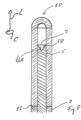
- Figure 1 shows a first exemplary embodiment of a waveguide 1 for treating inner walls of inner pathways of a human body with energy waves in a schematic cross-sectional view.
- the waveguide 1 may comprise a core 2 and a coating 3, through which the core 2 extends.
- the core 2 may be formed by a polymer or by silica glass.
- the core 2 may comprise or be provided with a cladding that may also be designated as an outer layer on the core 2.
- the cladding may comprise or by a polymer or a glass.
- the core 2 and the cladding may have different refractive indexes.
- the waveguide 1 comprises a first longitudinal end for receiving energy waves.
- the first longitudinal end may be adapted to be connected to a light source, e.g. a laser.
- the waveguide 1 comprises a second longitudinal end 4 for redirecting the energy waves that travelled from the first longitudinal end through the waveguide to the second longitudinal end 4.
- the first and second 4 longitudinal ends are opposite ends of the waveguide 1 along a longitudinal extend L of the waveguide 1. In case the waveguide 1 is arranged to be straight, the longitudinal extend L would be the longitudinal direction of the waveguide.
- the waveguide 1 can be flexible and can be bent, for example with a bending radius of less than 200 mm, less than 150 mm, less than 100 mm, less than 75 mm, down to approximately 50 mm or even less, and as the waveguide 1 needs not to be essentially straight for the definition of the invention, the expression longitudinal extend L is used instead of the expression longitudinal direction.
- the waveguide 1 and optionally the core 2 thereof comprises a lateral side 5 that extends from the first longitudinal end to the second longitudinal end 4 along the longitudinal extend L.
- the lateral side 5 may at least sectionwise be provided by the cladding.
- the second longitudinal end 4 comprises at least one redirection surface 6 provided by the waveguide and optionally by the core 2 thereof, the redirection surface 6 being unpolished.
- the redirection surface 6 may be free from any cladding.
- the redirection surface 6 may be formed by grinding the second end of the waveguide.
- the redirection surface 6 may be formed by laser treatment of the material of the second longitudinal end 4 of the waveguide 1 at least on the surface.
- the redirection surface 6 may comprise a predefined roughness.
- the roughness may be predefined by machining the waveguide 1 to form the redirection surface 6.
- the roughness has a roughness parameter R a that is between a lower value of 0,5 ⁇ m and an upper value of 10 ⁇ m, wherein the lower value may be 0,7 ⁇ m, 1 ⁇ m, 1,3 ⁇ m, 1,5 ⁇ m, 1,7 ⁇ m, 2 ⁇ m, 3 ⁇ m, 5 ⁇ m, 7 ⁇ m or less than10 ⁇ m.
- the upper value may be 7 ⁇ m, 5 ⁇ m, 3 ⁇ m, 2 ⁇ m, 1,7 ⁇ m, 1,5 ⁇ m, 1,3 ⁇ m, 1 ⁇ m, 0,7 ⁇ m or more than 0,5 ⁇ m.
- the roughness parameter R a may be 1,3 ⁇ m.
- the amplitude of the roughness may be similar to or even greater than the wavelength of light used for treating.
- the light may be infrared light or visible light.
- the wavelength may be between a lower and an upper value, wherein the lower value may be 380 nm, 400 nm, 450 nm, 495 nm, 500 nm, 550 nm, 570 nm, 590 nm, 620 nm, 750 nm, 800 nm, 1,4 ⁇ m, 2,2 ⁇ m, 3 ⁇ m, 8 ⁇ m, 15 ⁇ m or less than 1 mm.
- the upper value may be 1 mm, 15 ⁇ m, 8 ⁇ m, 3 ⁇ m, 2,2 ⁇ m, 1,4 ⁇ m, 800 nm, 750 nm, 620 nm, 590 nm, 570 nm, 550 nm, 500 nm, 495 nm, 450 nm, 400 nm or more than 380 nm.
- the amplitude of the roughness may correspond to the wavelengths of light used for treating multiplied with a factor of between a lower and an upper value, wherein the lower value may be greater than 1, 1,5, 2, 3, 4 or 5, and wherein the upper value may be 20, 15, 10, 7 or 6.
- the redirection surface 6 juts the lateral side 5 in the longitudinal extend L.
- the redirection surface 6 protrudes from the lateral side 5 in the longitudinal extend L and/or forms an extreme longitudinal end of the waveguide 1 or of the core 5 thereof.
- the redirection surface 6 may outline a cone shape, a pyramid shape or a wedge shape. Outlining one of the shapes may mean that the redirection surface 5 is the surface of the second longitudinal end 4 of the waveguide 1 or of the core 2 thereof, that, as such, has the respective shape.
- an angle W may be present between the opposite redirection surface sections 6A, 6B.
- the opposite redirection sections 6A, 6B may be symmetrical with respect to the longitudinal extend L at the second longitudinal end 4.
- the angle W may open against the longitudinal extend L, i.e. away from the second longitudinal end 4.
- the second longitudinal end 4 may comprise an end face 7 that is essentially aligned perpendicular to the longitudinal extend L at the second longitudinal end 4.
- the end face 7 is exemplarily shown as an end face 7 provided by the coating 3.
- the end face 7 may at least partly or even completely extend around the redirection surface 6 perpendicular to the longitudinal extend L of the waveguide 1 at the second longitudinal end.
- the end face 7 may extend in a circumferential direction C, the circumferential direction C extending perpendicular to and around the longitudinal extend L.
- the end face 7 may be arranged with a distance d between the end face 7 and the redirection surface 6.
- the distance d may be less than or about 5 mm, up to or about 5 mm, up to or about 7 mm, up to or about 10 mm, up to or about 15 mm or even up to or about 20 mm or even more.
- an adhesive may be arranged that affixes the position of ending element 10 at the second longitudinal end 4.
- the lateral side of the coating 3 may be free from overlap with the ending element 10.
- the outer diameter of the ending element 10 may be larger than the outer diameter of the waveguide 1, of the core 2 thereof, or of the coating 3 thereof.
- a total length H of the ending element may be less than or about 20 mm, less than or about 15 mm, less than or about 10 mm, less than or about 7 mm or even less than or about 5 mm.
- the length H may extend along the longitudinal extend L at the second longitudinal end 4.
- the ending element 10 may comprise a free volume 12, into which the waveguide 1 and at least the core 2 thereof can be introduced, preferably essentially without play perpendicular to the longitudinal extend L.
- a section of the free volume 12 may remain, which may be filled with a fluid, e.g. a liquid like water or a gas like air, or a vacuum may be present.
- a length h of the remaining section of the free volume 12 may extend between a contact part, at which the waveguide 1 and optionally the core 2 thereof contacts the ending element 10, and the closed end of the ending element 10 that delimits the free volume 12 in the longitudinal extend L.
- the length h may be between a contact part, at which the waveguide 1 and optionally the core 2 thereof contacts the ending element 10, and at end part, at which the tube-shaped part contacts the curved closed end.
- the redirection surface 6 may end within the tube-shaped part.
- the lengths h may be less than or about 5 mm, less than or about 4 mm, less than or about 3 mm, less than or about 2 mm, less than or about 1,5 mm, less than or about 1 mm or even less.
- Figure 2 shows another exemplary embodiment of the waveguide 1 in a schematic cross-sectional view.
- elements which in form and/or structure correspond to the elements of the exemplary embodiment of figure 1 , the same reference numerals are used.
- the differences with respect to the exemplary embodiment of figure 1 are mentioned below.
- the maximum diameter of the ending element 10 and an outer diameter of the waveguide 1 and particularly of the core 2 or of the coating 3 thereof may be essentially identical.
- the maximum diameter of the ending element 10 may be greater than the outer diameter of the waveguide 1 and particularly of the core 2 or of the coating 3 thereof may be essentially identical, as shown in figure 1 .
- the ending element 10 may overlap the lateral side 5 and/or may contact the end face 7 of the coating 3. Particularly, as shown in the exemplary embodiment of figure 2 , the ending element 10 may smoothly transition over the end face 7 onto an outer lateral surface of the coating 3, wherein the filler material 11 optionally provides for the smooth transition. Particularly, in case the diameter of the ending element 10 essentially corresponds to the diameter of the coating 3, the filler material 11 may fill a gap, groove or notch between the ending element 10 and the coating 3, the gap, groove or notch extending in the longitudinal extend L and the circumferential direction c.
- the waveguide 1 is formed with a cladding 13 on the outer lateral surface of the core 2.
- the cladding 13 may have a longitudinal end at the second longitudinal end 4.
- the longitudinal cladding end may be arranged at a distance D from the redirection surface 6.
- the distance D may be up to 1 mm, up to 2 mm, up to 3 mm or even up to 4 mm.
- the outer lateral side 5 may be the side of the core 2 or of the cladding 13.
- the waveguides 1 of all exemplary embodiments may be formed with or without the cladding 13.
- the cladding 13 may end at the redirection surface 6.
- Figures 3 to 7 disclose various exemplary embodiments of the waveguide 1, wherein the core 2 is depicted while the coating 3 is omitted.
- the same reference numerals are used.
- the differences with respect to the exemplary embodiments of the previous figures are mentioned below.
- the redirection surface 6 may form a recess that extends along or against the longitudinal extend L away from the second longitudinal end 4 and/or towards the first longitudinal end. Hence, the redirection surface 6 may be arranged between opposite sections of the lateral side 5 of the core 2.
- the redirection surface 6 may outline a cone shape, a pyramid shape or a wedge shape. As one example, the figures show the cone shape.
- Outlining one of the shapes may mean that the redirection surface 6 is the surface of the second longitudinal end 4 of the waveguide 1 or of the core 2 thereof, that, as such, delimits at least one side of a free volume that has the respective shape.
- the free volume may widen in the longitudinal extend L, i.e. away from the first longitudinal end and/or towards the second longitudinal end 4.
- the redirection surface 6 may form or delimit the lateral surface of the cone shaped free volume.
- the cone may be a truncated cone.
- the redirection surface 6 may form the lateral sides of the pyramid that form the apex of the pyramid or extend towards of the virtual shape of a truncated pyramid.
- the redirection surface 6 may form the lateral sides of the pyramid that form the apex of the wedge or extend towards of the virtual ape of a truncated wedge.
- the shapes may also be designated as concave or inverse shapes.
- an angle W may be present between the opposite redirection surface sections 6A, 6B.
- the opposite redirection sections 6A, 6B may be symmetrical with respect to the longitudinal extend L at the second longitudinal end 4.
- the angle W may open in the longitudinal extend L, i.e. towards the second longitudinal end 4.
- Figure 3 exemplarily shows the waveguide 1 without an ending element 10.
- the redirection surface 6 opens in the longitudinal extend L at the second longitudinal end 4.
- Figure 4 shows the waveguide 1 with an optional ending element 10.
- the lateral side 5 of the core 2 may be free from overlap from or free from contact with the ending element 10.
- Figure 4 exemplarily shows the waveguide 1 with a sphere-shaped ending element 10.
- the sphere-shaped ending element 10 may have a diameter that is larger than the maximum clear width S formed by the redirection surface 6.
- the clear width S extends perpendicular to the longitudinal extend L at the second longitudinal end 4 and between opposite parts of the redirection surface 6.
- the clear width S may correspond to the outer diameter E of the core 2.
- the clear width S may be smaller than the outer diameter E of the core 2.
- the core 2 may comprise an end face 8 that extends perpendicular to the longitudinal extend L at the second longitudinal end 4.
- the end face 8 may contact the redirection surface 6.
- the end face 8 may even contact the and at least partly or even completely extends around the redirection surface 6 perpendicular to the longitudinal extend L.
- a groove or notch between the sphere-shaped ending element 10 and the end face 8 may be filled with a filler material, which may be an adhesive affixing the sphere-shaped ending element 10 to the end face 8.
- the sphere-shaped ending element 10 may have a diameter such that it contacts the redirection surface 6 close to or at a line at which the redirection surface 6 contacts the end face 8.
- the lateral side 5 of the core 2 may be free from overlap from the ending element 10.
- Figure 5 exemplarily shows the waveguide 1 with an ending element 10 that is formed as a lens.
- the core 2 may correspond to the core 2 of the exemplary embodiment of figure 4 .
- the lens may have optical properties that direct light not redirected by the redirection surface 6 in a desired manner and may in particular disperse the light and may, hence, be a diverging, negative or diffuser lens.
- the ending element 10 of figure 5 may have a convex or concave side that faces away from the core 2 in the longitudinal extend L.
- a side of the ending element 10 that faces the core 2 may be flat and/or may contact the end face 8 at least partly.
- an edge of the lens may contact the end face 8.
- the end face 8 may be completely contacted by the side.
- the ending element 10 may be mounted and for example affixed and e.g. glued to the end face 8.
- the lateral side 5 of the core 2 may be free from overlap from the ending element 10.
- Figure 6 exemplarily shows the waveguide 1 with an ending element 10 that is formed as a coating on the redirection surface 6.
- the coating may be a reflective coating like a dielectric layer stack or a metal layer, the metal, for example, comprising or being a Nobel metal like gold.
- Figure 7 exemplarily shows the waveguide 1 with an ending element 10 that is formed by casting.
- the ending element 10 can be cast into the recess formed by the redirection surface 6 and may at least partly or even completely fill the recess.
- the ending element 10 can be cast over the second longitudinal end 4 with the redirection surface 6 jutting the lateral side 5.
- the cast ending element 10 may at least partly be formed with a convex or concave surface that faces away from the core 2 in the longitudinal extend L, the convex or concave surface being a lens surface.
- a surface of the cast ending element 10 that faces towards the core 2, i.e. against the longitudinal extend L, may at least partly or even completely be formed complementary to the redirection surface 6.
- the ending element 10 may be formed with a plate-shape, wherein the ending element 10 may be mounted to the end face 8 in the same manner as the lens shaped ending element 10 of figure 5 .
- the material of the cast ending element 10 may have an optical property that differs from the respective optical property of the material of the core 2.
- the optical property may be the refractive index.
- the material of the cast ending element 10 may have a refractive index that is lower than the refractive index of the core material.
- the material of the cast ending element 10 may be a so-called low-index material.
- Figure 8 depicts another exemplary embodiment of the waveguide 1 in a schematic cross-sectional view.
- elements which in form and/or structure correspond to the elements of the exemplary embodiments of the previous figures, the same reference numerals are used.
- the differences with respect to the exemplary embodiments of the previous figures are mentioned below.
- figure 8 shows the core 2 of the exemplary embodiment of figure 3 with the ending element 10 of figure 2 .
- At least the ending elements 10 of the exemplary embodiments of any of figures 5 , 6 or 7 may be added as additional ending element 10 to the exemplary embodiment of figure 8 .
Landscapes
- Health & Medical Sciences (AREA)
- Surgery (AREA)
- Physics & Mathematics (AREA)
- Life Sciences & Earth Sciences (AREA)
- Engineering & Computer Science (AREA)
- Medical Informatics (AREA)
- Nuclear Medicine, Radiotherapy & Molecular Imaging (AREA)
- Electromagnetism (AREA)
- Optics & Photonics (AREA)
- Biomedical Technology (AREA)
- Heart & Thoracic Surgery (AREA)
- Otolaryngology (AREA)
- Molecular Biology (AREA)
- Animal Behavior & Ethology (AREA)
- General Health & Medical Sciences (AREA)
- Public Health (AREA)
- Veterinary Medicine (AREA)
- Optical Integrated Circuits (AREA)
Claims (11)
- Guide d'ondes (1) pour traiter des parois intérieures de voies intérieures d'un corps humain avec des ondes d'énergie, le guide d'ondes (1) comprenantune première extrémité longitudinale pour recevoir des ondes d'énergie,une deuxième extrémité longitudinale (4) pour rediriger les ondes d'énergie qui ont voyagé de la première extrémité longitudinale à travers le guide d'ondes (1) vers la deuxième extrémité longitudinale (4),la première et la deuxième extrémité longitudinale (4) étant des extrémités opposées du guide d'ondes (1) le long d'une extension longitudinale (L) du guide d'ondes (1), etun côté latéral (5) qui s'étend de la première extrémité longitudinale à la deuxième extrémité longitudinale (4) le long de l'extension longitudinale (L),la deuxième extrémité longitudinale (2) comprenant au moins une surface de redirection (6) fournie par le guide d'ondes (2), la surface de redirection (6) n'étant pas polie,caractérisé en ce quela surface de redirection (6) comprend une rugosité prédéfinie avec un paramètre de rugosité Ra compris entre 0,5 µm et 10 µm.
- Guide d'ondes (1) selon la revendication 1, caractérisé en ce que la surface de redirection (6) est formée par meulage de la deuxième extrémité longitudinale (4) du guide d'ondes (4) et/ou par traitement au laser du matériau de la deuxième extrémité longitudinale (4) du guide d'ondes (1) au moins sur la surface.
- Guide d'ondes (1) selon la revendication 1 ou 2, caractérisé en ce que la surface de redirection (6) fait saillie sur le côté latéral (5) dans l'extension longitudinale (L).
- Guide d'ondes (1) selon la revendication 1 ou 2, caractérisé en ce que la surface de redirection (6) forme un renfoncement qui s'étend le long de l'extension longitudinale (L) de la deuxième extrémité longitudinale (4) vers la première extrémité longitudinale.
- Guide d'ondes (1) selon l'une quelconque des revendications 1 à 4, caractérisé en ce que la surface de redirection (6) dessine au moins partiellement une forme de cône, une forme de pyramide ou une forme de coin.
- Guide d'ondes (1) selon l'une quelconque des revendications 1 à 5, caractérisé en ce que la deuxième extrémité longitudinale (4) comprend une face d'extrémité (7, 8) du noyau (2) qui est essentiellement alignée perpendiculairement à l'extension longitudinale (L) à la deuxième extrémité longitudinale (4),la face d'extrémité (8) étant en contact avec la surface de redirection (6), oula face d'extrémité (7, 8) s'étendant au moins partiellement ou même complètement autour de la surface de redirection (6) perpendiculairement à l'extension longitudinale (L) du guide d'ondes (2) à la deuxième extrémité longitudinale (4), oula face d'extrémité (8) étant en contact avec la surface de redirection (6) et s'étendant au moins partiellement ou même complètement autour de la surface de redirection (6) perpendiculairement à l'extension longitudinale (L) du guide d'ondes (1) à la deuxième extrémité longitudinale (4), oula face d'extrémité (7) étant disposée à une certaine distance de la surface de redirection (6).
- Guide d'ondes (1) selon l'une quelconque des revendications 1 à 6, caractérisé en ce qu'un élément de terminaison (10) est prévu à la deuxième extrémité longitudinale (4).
- Guide d'ondes (1) selon la revendication 7 lorsqu'elle dépend de la revendication 6, caractérisé en ce que l'élément de terminaison (10) recouvre le côté latéral (5) et/ou est monté sur la face d'extrémité (7, 8).
- Guide d'ondes (1) selon la revendication 7 lorsqu'elle dépend de la revendication 6, caractérisé en ce que le côté latéral (5) est exempt de chevauchement avec l'élément de terminaison (10) et/ou l'élément de terminaison (10) est monté sur la face d'extrémité (7, 8).
- Guide d'ondes (1) selon l'une quelconque des revendications 7 à 9, caractérisé en ce qu'un diamètre maximal de l'élément de terminaison (10) et un diamètre du guide d'ondes (1) sont essentiellement identiques.
- Guide d'ondes (1) selon l'une quelconque des revendications 7 à 10, caractérisé en ce que l'élément de terminaison (10) comprend ou est un capuchon de terminaison, une sphère, une lentille, une plaque, un élément formé par moulage et/ou un revêtement.
Priority Applications (2)
| Application Number | Priority Date | Filing Date | Title |
|---|---|---|---|
| EP22170453.9A EP4268754B1 (fr) | 2022-04-28 | 2022-04-28 | Guide d'ondes pour traiter des parois internes de voies internes d'un corps humain |
| PCT/EP2023/061103 WO2023209085A1 (fr) | 2022-04-28 | 2023-04-27 | Guide d'ondes pour le traitement de parois intérieures de voies intérieures d'un corps humain |
Applications Claiming Priority (1)
| Application Number | Priority Date | Filing Date | Title |
|---|---|---|---|
| EP22170453.9A EP4268754B1 (fr) | 2022-04-28 | 2022-04-28 | Guide d'ondes pour traiter des parois internes de voies internes d'un corps humain |
Publications (3)
| Publication Number | Publication Date |
|---|---|
| EP4268754A1 EP4268754A1 (fr) | 2023-11-01 |
| EP4268754B1 true EP4268754B1 (fr) | 2024-05-29 |
| EP4268754C0 EP4268754C0 (fr) | 2024-05-29 |
Family
ID=81392623
Family Applications (1)
| Application Number | Title | Priority Date | Filing Date |
|---|---|---|---|
| EP22170453.9A Active EP4268754B1 (fr) | 2022-04-28 | 2022-04-28 | Guide d'ondes pour traiter des parois internes de voies internes d'un corps humain |
Country Status (2)
| Country | Link |
|---|---|
| EP (1) | EP4268754B1 (fr) |
| WO (1) | WO2023209085A1 (fr) |
Family Cites Families (13)
| Publication number | Priority date | Publication date | Assignee | Title |
|---|---|---|---|---|
| EP0292621B1 (fr) * | 1987-05-26 | 1994-12-14 | Surgical Laser Technologies, Inc. | Embout laser de contact ou d'insertion à angle large de radiation |
| JP2882814B2 (ja) * | 1989-08-24 | 1999-04-12 | 株式会社エス・エル・ティ・ジャパン | レーザ光の照射装置 |
| EP0673627B1 (fr) * | 1994-03-23 | 2000-01-05 | Yasuo Hashimoto | Cathéter à fibre optique |
| US6270492B1 (en) * | 1994-09-09 | 2001-08-07 | Cardiofocus, Inc. | Phototherapeutic apparatus with diffusive tip assembly |
| US6522806B1 (en) * | 2001-02-16 | 2003-02-18 | Ethicon Endo-Surgury, Inc. | Optical fiber including a diffuser portion and continuous sleeve for the transmission of light |
| US20050165462A1 (en) * | 2002-02-05 | 2005-07-28 | Roland Bays | Light delivery device using conical diffusing system and method of forming same |
| DE10256139A1 (de) * | 2002-04-24 | 2003-11-20 | Univ Muenchen L Maximilians | Lichtapplikator und Verfahren zur Herstellung eines Streukörpers |
| US7274847B2 (en) * | 2004-11-16 | 2007-09-25 | Biotex, Inc. | Light diffusing tip |
| US20080177257A1 (en) * | 2007-01-23 | 2008-07-24 | Smith Ronald T | Thermally robust illumination probe tip |
| KR20110091295A (ko) * | 2010-02-05 | 2011-08-11 | 광주과학기술원 | 다방면 조사 광섬유 프로브 및 이를 위한 제조방법 |
| WO2017142232A1 (fr) * | 2016-02-15 | 2017-08-24 | (주)미린트 | Dispositif d'émission de lumière de dispositif de traitement de la rhinite |
| CN111031953B (zh) * | 2017-07-06 | 2023-06-20 | 波士顿科学医学有限公司 | 光纤和相关系统 |
| CN111110346B (zh) * | 2019-12-31 | 2021-03-09 | 华科精准(北京)医疗科技有限公司 | 用于激光间质热疗系统的装置 |
-
2022
- 2022-04-28 EP EP22170453.9A patent/EP4268754B1/fr active Active
-
2023
- 2023-04-27 WO PCT/EP2023/061103 patent/WO2023209085A1/fr unknown
Also Published As
| Publication number | Publication date |
|---|---|
| WO2023209085A1 (fr) | 2023-11-02 |
| EP4268754C0 (fr) | 2024-05-29 |
| EP4268754A1 (fr) | 2023-11-01 |
Similar Documents
| Publication | Publication Date | Title |
|---|---|---|
| US10993768B2 (en) | Radial emissions from optical fibers | |
| US5495541A (en) | Optical delivery device with high numerical aperture curved waveguide | |
| US4787708A (en) | Apparatus for continuously controlled emission of light from prism light guide | |
| US6829411B2 (en) | Wide angle light diffusing optical fiber tip | |
| US6361530B1 (en) | Durable fiber optic diffuser tip and method of making same | |
| US8285097B2 (en) | Annular side fire optical device for laterally redirecting electromagnetic radiation | |
| US11432725B2 (en) | Optical probe and assembly thereof having specific optical component adhesive configuration | |
| US20190293886A1 (en) | Flexible optical fiber ribbon with ribbon body flexibility recesses | |
| US9122009B1 (en) | Fiber optic termination | |
| US9223089B1 (en) | Fiber optic termination | |
| JP5187915B2 (ja) | 側方出射装置の製造方法 | |
| CN104254734A (zh) | 带有多面光学元件的多光斑激光探针 | |
| US11826097B2 (en) | Forming radial emissions from optical fibers | |
| JP2679787B2 (ja) | 光ファイバーコネクター | |
| EP4268754B1 (fr) | Guide d'ondes pour traiter des parois internes de voies internes d'un corps humain | |
| IL113674A (en) | Side-emitting optical fibers for lasers with orientation markings | |
| US9618700B1 (en) | Orthogonal output optical fiber | |
| US20200405390A1 (en) | Device for treatment of body tissue | |
| US6811328B2 (en) | Optical fiber splicing using surface tension | |
| JP4550323B2 (ja) | 光導波路の形成方法 | |
| US20240008922A1 (en) | Ultrahydrophobic laser coating and method | |
| JP2015073846A (ja) | 光干渉断層撮像用光プローブ及びその製造方法 | |
| JPH0363377B2 (fr) | ||
| JPWO2020121887A1 (ja) | 光ファイバプローブ | |
| CN221039507U (zh) | 一种侧射光纤组件 |
Legal Events
| Date | Code | Title | Description |
|---|---|---|---|
| PUAI | Public reference made under article 153(3) epc to a published international application that has entered the european phase |
Free format text: ORIGINAL CODE: 0009012 |
|
| STAA | Information on the status of an ep patent application or granted ep patent |
Free format text: STATUS: EXAMINATION IS IN PROGRESS |
|
| 17P | Request for examination filed |
Effective date: 20230406 |
|
| AK | Designated contracting states |
Kind code of ref document: A1 Designated state(s): AL AT BE BG CH CY CZ DE DK EE ES FI FR GB GR HR HU IE IS IT LI LT LU LV MC MK MT NL NO PL PT RO RS SE SI SK SM TR |
|
| GRAP | Despatch of communication of intention to grant a patent |
Free format text: ORIGINAL CODE: EPIDOSNIGR1 |
|
| STAA | Information on the status of an ep patent application or granted ep patent |
Free format text: STATUS: GRANT OF PATENT IS INTENDED |
|
| INTG | Intention to grant announced |
Effective date: 20240102 |
|
| GRAS | Grant fee paid |
Free format text: ORIGINAL CODE: EPIDOSNIGR3 |
|
| GRAA | (expected) grant |
Free format text: ORIGINAL CODE: 0009210 |
|
| STAA | Information on the status of an ep patent application or granted ep patent |
Free format text: STATUS: THE PATENT HAS BEEN GRANTED |
|
| REG | Reference to a national code |
Ref country code: DE Ref legal event code: R081 Ref document number: 602022003639 Country of ref document: DE Owner name: OBERON GMBH FIBER TECHNOLOGIES, DE Free format text: FORMER OWNER: ANMELDERANGABEN UNKLAR / UNVOLLSTAENDIG, 80297 MUENCHEN, DE |
|
| AK | Designated contracting states |
Kind code of ref document: B1 Designated state(s): AL AT BE BG CH CY CZ DE DK EE ES FI FR GB GR HR HU IE IS IT LI LT LU LV MC MK MT NL NO PL PT RO RS SE SI SK SM TR |
|
| REG | Reference to a national code |
Ref country code: CH Ref legal event code: EP |
|
| REG | Reference to a national code |
Ref country code: IE Ref legal event code: FG4D |
|
| REG | Reference to a national code |
Ref country code: DE Ref legal event code: R096 Ref document number: 602022003639 Country of ref document: DE |
|
| U01 | Request for unitary effect filed |
Effective date: 20240611 |
|
| U07 | Unitary effect registered |
Designated state(s): AT BE BG DE DK EE FI FR IT LT LU LV MT NL PT SE SI Effective date: 20240620 |