EP4267779B1 - Mehrstrahlluftmesser zur kontrolle der schichtdicke von metallbeschichtungen - Google Patents
Mehrstrahlluftmesser zur kontrolle der schichtdicke von metallbeschichtungen Download PDFInfo
- Publication number
- EP4267779B1 EP4267779B1 EP21814810.4A EP21814810A EP4267779B1 EP 4267779 B1 EP4267779 B1 EP 4267779B1 EP 21814810 A EP21814810 A EP 21814810A EP 4267779 B1 EP4267779 B1 EP 4267779B1
- Authority
- EP
- European Patent Office
- Prior art keywords
- nozzle
- wiping device
- gas wiping
- gas
- supports
- Prior art date
- Legal status (The legal status is an assumption and is not a legal conclusion. Google has not performed a legal analysis and makes no representation as to the accuracy of the status listed.)
- Active
Links
Images


Classifications
-
- C—CHEMISTRY; METALLURGY
- C23—COATING METALLIC MATERIAL; COATING MATERIAL WITH METALLIC MATERIAL; CHEMICAL SURFACE TREATMENT; DIFFUSION TREATMENT OF METALLIC MATERIAL; COATING BY VACUUM EVAPORATION, BY SPUTTERING, BY ION IMPLANTATION OR BY CHEMICAL VAPOUR DEPOSITION, IN GENERAL; INHIBITING CORROSION OF METALLIC MATERIAL OR INCRUSTATION IN GENERAL
- C23C—COATING METALLIC MATERIAL; COATING MATERIAL WITH METALLIC MATERIAL; SURFACE TREATMENT OF METALLIC MATERIAL BY DIFFUSION INTO THE SURFACE, BY CHEMICAL CONVERSION OR SUBSTITUTION; COATING BY VACUUM EVAPORATION, BY SPUTTERING, BY ION IMPLANTATION OR BY CHEMICAL VAPOUR DEPOSITION, IN GENERAL
- C23C2/00—Hot-dipping or immersion processes for applying the coating material in the molten state without affecting the shape; Apparatus therefor
- C23C2/14—Removing excess of molten coatings; Controlling or regulating the coating thickness
- C23C2/16—Removing excess of molten coatings; Controlling or regulating the coating thickness using fluids under pressure, e.g. air knives
-
- B—PERFORMING OPERATIONS; TRANSPORTING
- B05—SPRAYING OR ATOMISING IN GENERAL; APPLYING FLUENT MATERIALS TO SURFACES, IN GENERAL
- B05C—APPARATUS FOR APPLYING FLUENT MATERIALS TO SURFACES, IN GENERAL
- B05C11/00—Component parts, details or accessories not specifically provided for in groups B05C1/00 - B05C9/00
- B05C11/02—Apparatus for spreading or distributing liquids or other fluent materials already applied to a surface ; Controlling means therefor; Control of the thickness of a coating by spreading or distributing liquids or other fluent materials already applied to the coated surface
- B05C11/06—Apparatus for spreading or distributing liquids or other fluent materials already applied to a surface ; Controlling means therefor; Control of the thickness of a coating by spreading or distributing liquids or other fluent materials already applied to the coated surface with a blast of gas or vapour
-
- C—CHEMISTRY; METALLURGY
- C23—COATING METALLIC MATERIAL; COATING MATERIAL WITH METALLIC MATERIAL; CHEMICAL SURFACE TREATMENT; DIFFUSION TREATMENT OF METALLIC MATERIAL; COATING BY VACUUM EVAPORATION, BY SPUTTERING, BY ION IMPLANTATION OR BY CHEMICAL VAPOUR DEPOSITION, IN GENERAL; INHIBITING CORROSION OF METALLIC MATERIAL OR INCRUSTATION IN GENERAL
- C23C—COATING METALLIC MATERIAL; COATING MATERIAL WITH METALLIC MATERIAL; SURFACE TREATMENT OF METALLIC MATERIAL BY DIFFUSION INTO THE SURFACE, BY CHEMICAL CONVERSION OR SUBSTITUTION; COATING BY VACUUM EVAPORATION, BY SPUTTERING, BY ION IMPLANTATION OR BY CHEMICAL VAPOUR DEPOSITION, IN GENERAL
- C23C2/00—Hot-dipping or immersion processes for applying the coating material in the molten state without affecting the shape; Apparatus therefor
- C23C2/14—Removing excess of molten coatings; Controlling or regulating the coating thickness
- C23C2/16—Removing excess of molten coatings; Controlling or regulating the coating thickness using fluids under pressure, e.g. air knives
- C23C2/18—Removing excess of molten coatings from elongated material
- C23C2/20—Strips; Plates
-
- C—CHEMISTRY; METALLURGY
- C23—COATING METALLIC MATERIAL; COATING MATERIAL WITH METALLIC MATERIAL; CHEMICAL SURFACE TREATMENT; DIFFUSION TREATMENT OF METALLIC MATERIAL; COATING BY VACUUM EVAPORATION, BY SPUTTERING, BY ION IMPLANTATION OR BY CHEMICAL VAPOUR DEPOSITION, IN GENERAL; INHIBITING CORROSION OF METALLIC MATERIAL OR INCRUSTATION IN GENERAL
- C23C—COATING METALLIC MATERIAL; COATING MATERIAL WITH METALLIC MATERIAL; SURFACE TREATMENT OF METALLIC MATERIAL BY DIFFUSION INTO THE SURFACE, BY CHEMICAL CONVERSION OR SUBSTITUTION; COATING BY VACUUM EVAPORATION, BY SPUTTERING, BY ION IMPLANTATION OR BY CHEMICAL VAPOUR DEPOSITION, IN GENERAL
- C23C2/00—Hot-dipping or immersion processes for applying the coating material in the molten state without affecting the shape; Apparatus therefor
- C23C2/34—Hot-dipping or immersion processes for applying the coating material in the molten state without affecting the shape; Apparatus therefor characterised by the shape of the material to be treated
- C23C2/36—Elongated material
- C23C2/40—Plates; Strips
Definitions
- the present invention relates to a multi-slot gas wiping device for controlling the thickness of a molten metallic coating applied on a metal strip.
- Gas wiping devices are used to control the thickness of a metallic coating applied on a moving metal strip, such as a steel strip.
- the metallic coating is applied by means of hot dip coating wherein in a continuous or semi-continuous process a metal strip passes as part of the process through a bath of molten metal of for instance Zn, Zn + Fe alloy, Zn + Al or Zn + Mg + Al.
- the metal strip leaves the bath in an about vertical direction after which the excess of the applied metallic coating is blown off with a high pressure air/gas wiping device also known as "air knife".
- the removal of excess metallic coating from the moving strip is in fact the control of the thickness of the applied metallic coating.
- the applied coating should fulfil requirements like an exact predefined thickness and uniform thickness over the complete coated steel strip. This is important not only to be able to subject the coated steel strip to forming operations but also for the final appearance of the final steel product formed from the coated steel strip.
- the gas wiping device should discharge a uniform gas jet over the total width of the gas nozzle of the gas wiping device which means that the gas jet should be of uniform velocity and pressure. This implies high standards for the construction of the gas wiping device and its gas discharge nozzle.
- EP3190204 discloses a method for manufacturing molten metal plated steel strip.
- Patent documents WO 2008/069362 A1 , JP H10 204599 A , EP 3 190 204 A1 and WO 2018/114248 A1 disclose gas wiping devices to be used in hot dip coating processes for adjusting the coating thickness of the molten metal applied on a substrate. In these documents it is disclosed different multi-jet gas knives designs of the wiping nozzles to achieve homogeneous gas flow on the coating.
- the coating weight can be influenced by the knife to strip distance, the angle of the primary and auxiliary jets, the gap width of the primary and auxiliary nozzles and the separation between the main- and auxiliary jets.
- a higher wiping efficiency requires a tilt angle between the auxiliary jet and the main jet.
- CFD has shown that the inlet pressure of the auxiliary jet flow rate should be a fraction of the flow rate of the main jet. Compared to a conventional air knife, this configuration will need longer nozzles to achieve the same flow rate at the primary nozzle, resulting in a lower stiffness of the nozzle and an unstable air flow.
- the nozzle of the multi-jet air knife can be easily exchanged, and the gap setting can be adjusted separately.
- a multi-slot gas wiping device for controlling the thickness of a molten metallic coating on a moving metal strip according to claim 1, comprising
- the nozzle system of the wiping device comprises two nozzle components, each nozzle comprising an inner part and an outer part,
- each nozzle comprising an inner part and an outer part
- the present invention therefore provides a device of great simplicity which can be easily implemented in a commercial galvanizing line.
- Sufficient stiffness, and hence a stable air flow, is introduced via the plurality of support in the outer nozzle lips.
- the amount, shape and thickness of the supports is not particularly limited.
- the supports are spaced at an interval in a range of 5 - 15 cm, preferably in a range of 5 - 10 cm.
- the density of the supports is preferably at least 15 supports per meter length. In a preferred embodiment, the supports are spaced at an even interval over the length of the nozzle lip.
- the wiping device according to the invention is a multi-slot air-knife comprising a main jet and an auxiliary jet.
- the definitions wiping device and air-knife can be used interchangeably.
- the length of the gas wiping device is not particularly limited and should preferably be chosen such that it can accommodate the widest strip size, typically up to 2500 mm.
- the arrangement for the multi-slot air-knife should be such that the centreline of the main and the auxiliary jet coincide at a same point on the strip. This can be influenced by the knife to strip distance (Z), the angle ⁇ of the inner nozzle lips, the angle ⁇ of the outer nozzle lips, the gap width of the primary nozzle (d), the gap width of the auxiliary nozzle (d a ) and the separation (a) between the main- and auxiliary jets.
- the inner and outer part of the nozzle components of the gas wiping are detachable connected.
- This allows for an easy exchange of the nozzle and has the advantage that the gap width d a of the auxiliary nozzle can be easily adjusted according to the required specifications.
- the gap width d a of the auxiliary nozzle may be determined by an offset at the outer ends of the outer nozzle lip or by an indentation of the outer nozzle lip.
- the outer part itself is made in one piece, for ease of manufacturing.
- the nozzle components are detachable connected. This allows for an easy exchange of the nozzle and allows for an easy adjustment of the gap d of the primary nozzle, for example by changing the shim.
- the nozzle system can be made of four modular parts, which can be easily assembled together.
- the inner nozzle lips are tilted at an angle ⁇ in the range of 10 - 20 ° measured from the centreline.
- the angle ⁇ is preferably in the range of 10 - 20 °, more preferably 15°, such that the highest impingement pressure on the strip can be achieved.
- the outer nozzle lips are tilted at an angle ⁇ in the range of 20 - 40 ° measured from the centreline.
- the angle ⁇ is preferably in the range of 10 - 20 °, more preferably 15 °, such that the highest impingement pressure on the strip can be achieved.
- the two nozzle components are mirror images of each other.
- the manufacturing process becomes easier.
- such a configuration will result in a stable air flow.
- the plurality of supports in the outer parts are chamfered at the nozzle opening in a range of 4 - 12 °, in order to reduce vortex shedding, corresponding to an encapsulated angle at a range of 8 - 24 degree.
- the supports are chamfered in a range of 6 - 10 °, most preferably at 8 °.
- the first elongated opening is fed with a first pressurized gas and the auxiliary elongated openings are fed with a second pressurized gas.
- the gas flow in the auxiliary jets is preferably lower than the gas flow to the main jet.
- the gas flow of the second pressurized gas is 20% of the gas flow of the main jet.
- flow regulator means can be provided.
- auxiliary jets are being attached directly on the main nozzle an air knife design with separate gas feeding for both the main and auxiliary nozzle is preferred. This can be realized by adding a casing to the nozzle which can lead the wiping gas to the nozzles Preferably, separate feeding channels for the pressurized gas for both the main and the auxiliary nozzles are provided.
- the gas wiping device comprises a casing with two compartments, configured as such that the first pressurized gas is guided through a first compartment to the first elongated opening and the second pressurized gas is guided through a second compartment to the auxiliary elongated openings.
- the casing can be mounted to the nozzle to lead the wiping gas to lead the wiping gas to the nozzles.
- the main jet can be fed from one or two sides of the air knife or from the back.
- the auxiliary jets can be fed from the back or from one or two sides, or from the top of the air knife.
- one wiping gas is provided at the outer sides of the casing and the other wiping gas via the back, as this set up will fit the configuration of most hot-dip galvanizing plants.
- the casing comprises gas inlets at the outer sides in fluid connection with the first compartment.
- the casing of the gas wiping device comprises a gas inlet at the back in fluid connection with the second compartment to supply wiping gas to the auxiliary jets, to prevent too high maximum gas velocity and pressure drop. It has been chosen to feed the wiping gas for main jet on both sides of the casing and the auxiliary jets from the back. As feeding the auxiliary nozzle from the sides would possibly lead to too high maximum gas velocity and pressure drop.
- the first compartment of the casing comprises calibration means.
- calibration means Prior to the main nozzle calibration means are preferably added to break vortices present in the flow to the main nozzle.
- calibration holes Preferably, calibration holes should be added to break vortices present in the flow before entering the main nozzle.
- the second compartment of the casing comprises a plurality of supports.
- the plurality of supports will achieve a higher stiffness in the ducts to the auxiliary nozzles, ensuring a more stable air flow.
- the plurality of supports of the casing are aligned with the plurality of supports of the outer part of the nozzle components. By aligning the supports the air flow will be most stable.
- the plurality of supports of the casing are chamfered at the gas inlet at the back to reduce vortices.
- the plurality of supports of the casing are chamfered in a range of 4 - 12 °, more preferably in a range of 6 - 10 °, most preferably at 8 °.
- the ratio of the Reynolds number of the first pressurized fluid to the second pressurized fluid is in the range of 2:1 to 10:1, preferably 4:1 to 8:1, most preferably 6:1.
- the pressurized fluids are not particularly limited and can be air, nitrogen, CO 2 , or argon.
- the pressurized fluid is air or nitrogen.
- FIG. 1 Shows an exploded view of an exemplary embodiment of a nozzle system of a wiping device according to the invention.
- the nozzle system comprises two nozzle components 10a and 10b, each comprising two inner parts and two outer parts. Each inner part comprises an inner nozzle lip 1a, 1b and two outer ends 3a, 3b, thereby forming an envelope.
- the inner parts are detachable connected with a shim (8). By varying the size of the shim the gap d of the first elongated opening can be set.
- the gap d is typically between 0.5 - 5.0 mm, and is set according to the coating requirements of the final product.
- Each outer part comprises an outer nozzle lip 2a, 2b, two outer ends 4a, 4b and a plurality of supports 5a, 6a, 7a.
- the plurality of supports are preferably perpendicular to the outer nozzle lips.
- the supports have a width of 0.4 -20 mm each and are preferably spaced apart evenly over the length of the wiping device, to provide stiffness to the wiping device.
- the outer part is detachable connected to the respective inner part, for example with fasteners through the supports.
- the gap width d a of the auxiliary elongated opening is defined by an offset at the outer ends at the outer nozzle lip or by an indentation of the outer nozzle lip.
- the gap d a of the auxiliary elongated opening can be set.
- the gap d a is typically between 0.1 - 1.5 mm, and is manufactured according to the coating requirements of the final product.
- the inner part and outer parts may be made via milling, moulding, 3d printing or the like, as well known to a person skilled in the art.
- the outer parts are preferably machined from mild steel.
- the outer part is divided into sections by supports perpendicular to the nozzle opening for stiffness. These supports may be used for mounting the outer part to the inner part.
- the supports are preferably chamfered 8 degrees ( FIG. 2 , detail G, top view) at the nozzle opening to prevent vortex shedding.
- the jet opening on the auxiliary nozzle can be milled to achieve the required gap d a . Following machining/milling the outer part may be treated to harden the surface.
- the inner nozzles lips are at an angle ⁇ of 15 ° with respect to the centre line 50 and the outer nozzle lips are at an angle ⁇ of 30 ° with respect to the centre line 50 ( FIG. 2 , detail B, side view).
- the nozzle lips may be milled at the nozzle opening to obtain the desired gap width of the primary nozzle (d), the desired gap width of the auxiliary nozzle (d a ) and the separation (a) between the main- and auxiliary jets.
- the nozzle lips are milled as such that the primary nozzle gap width is 1.0-1.5 mm, the auxiliary nozzle gap width is 1.0 - 1.5 mm and the separation (a) is 1 mm.
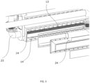
- FIG. 3 shows an exemplary embodiment of the wiping device according to the invention, including a casing with two compartments, configured such that the first pressurized fluid (23) is guided through a first compartment (13) to the first elongated opening via the outer sides of the casing and the second pressurized fluid (24) is guided through a second compartment (13) via the back of the casing to the auxiliary elongated openings.
- holes serve as calibration means in the first compartment, to break vortices present in the flow to the main nozzle.
- the second compartment comprises supports, preferably aligned with the supports of the outer parts of the nozzle system.
- the casing can be attached to the wiping device as common to the person skilled in the art. One possibility is to fasten the nozzle system and casing with fasteners, through openings (9) in the supports.
- the modular design of the wiping device according to the invention results in a device that can be easily assembled and disassembled, and can be used in a commercial galvanizing line. Furthermore, the wiping device can be fed with two separate air flows and has sufficient stiffness.
Landscapes
- Chemical & Material Sciences (AREA)
- Chemical Kinetics & Catalysis (AREA)
- Engineering & Computer Science (AREA)
- Materials Engineering (AREA)
- Mechanical Engineering (AREA)
- Metallurgy (AREA)
- Organic Chemistry (AREA)
- Coating With Molten Metal (AREA)
- Coating Apparatus (AREA)
- Nozzles (AREA)
Claims (15)
- Mehrschlitz-Gasabstreifvorrichtung zum Kontrollieren der Dicke einer geschmolzenen Metallbeschichtung auf einem sich bewegenden Metallstreifen, umfassend• ein Düsensystem mit einer Primärdüse mit einer ersten länglichen Öffnung und zwei Hilfsdüsen mit jeweils einer zusätzlichen länglichen Öffnung, wobei die Primärdüse und die Hilfsdüsen parallel angeordnet sind, und• wobei das Düsensystem zwei Düsenkomponenten (10a, 10b) umfasst, die spiegelbildlich zueinander sind und mit einem Einlegestück (8) aneinander befestigt sind, wodurch die erste längliche Öffnung mit einer Spaltbreite d definiert wird, und• wobei jede Düsenkomponente einen inneren Teil und einen äußeren Teil umfasst, die die zusätzlichen länglichen Öffnungen mit einer Spaltbreite da definieren, und• wobei jeder innere Teil eine innere Düsenlippe (1a, 1b) und zwei äußere Enden an der inneren Düsenlippe (3a, 3b) umfasst, wodurch eine Umhüllung gebildet wird, und• wobei jeder äußere Teil eine äußere Düsenlippe (2a, 2b), zwei äußere Enden an der äußeren Düsenlippe (4a, 4b) und eine Vielzahl von Stützen (5a, 6a, 7a) umfasst, wobei die Vielzahl von Stützen mit einer senkrechten Ausrichtung zu der äußeren Düsenlippe und zu einer Düsenöffnung in die äußeren Düsenlippen (2a, 2b) integriert sind.
- Gasabstreifvorrichtung nach Anspruch 1, wobei der innere und der äußere Teil der Düsenkomponenten lösbar verbunden sind.
- Gasabstreifvorrichtung nach Anspruch 2 oder 3, wobei die Düsenkomponenten lösbar verbunden sind.
- Gasabstreifvorrichtung nach Anspruch 1, wobei die Spaltbreite da der zusätzlichen länglichen Öffnung vorzugsweise zwischen 0,2 - 3 mm, bevorzugter 0,3 - 1,5 mm beträgt, und wobei die Spaltbreite da durch einen Versatz an den äußeren Enden an der äußeren Düsenlippe oder durch eine Vertiefung der äußeren Düsenlippe definiert ist.
- Gasabstreifvorrichtung nach einem der vorhergehenden Ansprüche, wobei der äußere Teil in einem Stück gefertigt ist.
- Gasabstreifvorrichtung nach einem der vorhergehenden Ansprüche, wobei die inneren Düsenlippen in einem Winkel α im Bereich von 10 - 20°, gemessen von der Mittellinie (50), vorliegen und/oder wobei die äußeren Düsenlippen in einem Winkel β im Bereich von 20 - 40°, gemessen von der Mittellinie (50), vorliegen.
- Gasabstreifvorrichtung nach einem der vorhergehenden Ansprüche, wobei die Vielzahl von Stützen an der Düsenöffnung in einem Bereich von 4 - 12° abgeschrägt sind.
- Gasabstreifvorrichtung nach einem der vorhergehenden Ansprüche, wobei die erste längliche Öffnung mit einem ersten unter Druck stehenden Fluid gespeist wird und die zusätzlichen länglichen Öffnungen mit einem zweiten unter Druck stehenden Fluid gespeist werden.
- Gasabstreifvorrichtung nach Anspruch 8, ferner ein Gehäuse mit zwei Kammern umfassend, die so konfiguriert sind, dass das erste unter Druck stehende Fluid durch eine erste Kammer (13) zu der ersten länglichen Öffnung geführt wird und das zweite unter Druck stehende Fluid durch eine zweite Kammer (14) zu den zusätzlichen länglichen Öffnungen geführt wird.
- Gasabstreifvorrichtung nach Anspruch 9, wobei das Gehäuse an den Außenseiten Gaseinlässe (23) umfasst, die in Fluidverbindung mit der ersten Kammer stehen.
- Gasabstreifvorrichtung nach Anspruch 9 oder 10, wobei die erste Kammer des Gehäuses Kalibrierungsmittel zum Reduzieren von Wirbeln umfasst.
- Gasabstreifvorrichtung nach einem der Ansprüche 9 - 11, wobei das Gehäuse an der Rückseite einen Gaseinlass (24) umfasst, der in Fluidverbindung mit der zweiten Kammer steht.
- Gasabstreifvorrichtung nach einem der Ansprüche 9 - 12, wobei die zweite Kammer des Gehäuses eine Vielzahl von Stützen umfasst.
- Gasabstreifvorrichtung nach Anspruch 13, wobei die Vielzahl von Stützen des Gehäuses mit der Vielzahl von Stützen des äußeren Teils der Düsenkomponenten ausgerichtet ist.
- Gasabstreifvorrichtung nach Anspruch 13 oder 14, wobei die Vielzahl von Stützen des Gehäuses an dem Gaseinlass an der Rückseite abgeschrägt sind.
Applications Claiming Priority (2)
| Application Number | Priority Date | Filing Date | Title |
|---|---|---|---|
| EP20216574 | 2020-12-22 | ||
| PCT/EP2021/083162 WO2022135828A1 (en) | 2020-12-22 | 2021-11-26 | Multi-jet air knife |
Publications (2)
| Publication Number | Publication Date |
|---|---|
| EP4267779A1 EP4267779A1 (de) | 2023-11-01 |
| EP4267779B1 true EP4267779B1 (de) | 2024-09-04 |
Family
ID=73856854
Family Applications (1)
| Application Number | Title | Priority Date | Filing Date |
|---|---|---|---|
| EP21814810.4A Active EP4267779B1 (de) | 2020-12-22 | 2021-11-26 | Mehrstrahlluftmesser zur kontrolle der schichtdicke von metallbeschichtungen |
Country Status (8)
| Country | Link |
|---|---|
| US (1) | US20240052473A1 (de) |
| EP (1) | EP4267779B1 (de) |
| JP (1) | JP2024501277A (de) |
| KR (1) | KR20230122606A (de) |
| CN (1) | CN116648311A (de) |
| ES (1) | ES2993413T3 (de) |
| FI (1) | FI4267779T3 (de) |
| WO (1) | WO2022135828A1 (de) |
Citations (4)
| Publication number | Priority date | Publication date | Assignee | Title |
|---|---|---|---|---|
| EP0359527A2 (de) * | 1988-09-13 | 1990-03-21 | Australian Wire Industries Pty. Limited | Abstreifdüse |
| EP0692549A1 (de) * | 1994-07-14 | 1996-01-17 | Unitas S.A. | Vorrichtung und Verfahren zum Kontrollieren der Beschichtungsgewicht eines metallüberzuges mittels Blasdüsen |
| EP3190204A2 (de) * | 2006-05-12 | 2017-07-12 | JFE Steel Corporation | HERSTELLUNGSVERFAHREN FüR EIN HEISSVERZINKTES STAHLBAND |
| WO2021256079A1 (ja) * | 2020-06-19 | 2021-12-23 | Jfeスチール株式会社 | ガスワイピングノズル及び溶融金属めっき金属帯の製造方法 |
Family Cites Families (14)
| Publication number | Priority date | Publication date | Assignee | Title |
|---|---|---|---|---|
| US4346129A (en) * | 1981-03-02 | 1982-08-24 | Republic Steel Corporation | Method and apparatus for thickness control of a coating |
| US5140940A (en) * | 1991-01-08 | 1992-08-25 | Atochem North America, Inc. | Apparatus for depositing a metal-oxide coating on glass articles |
| AU630281B2 (en) * | 1991-03-06 | 1992-10-22 | John Lysaght (Australia) Limited | Jet stripping apparatus |
| FR2726288B1 (fr) * | 1994-10-27 | 1997-01-17 | Clecim Sa | Dispositif a lame d'air pour le reglage de l'epaisseur d'un depot |
| JPH10204599A (ja) * | 1997-01-22 | 1998-08-04 | Nisshin Steel Co Ltd | 溶融めっき付着量の制御方法及びガスワイピングノズル |
| JP4779529B2 (ja) * | 2005-09-22 | 2011-09-28 | Jfeスチール株式会社 | 溶融金属めっき鋼帯の製造方法およびガスワイピングノズル |
| KR100843923B1 (ko) * | 2006-12-08 | 2008-07-03 | 주식회사 포스코 | 다단 노즐형 가스 와이핑 장치 |
| EP2045349A1 (de) * | 2007-10-05 | 2009-04-08 | Linde Aktiengesellschaft | Vorrichtung und Verfahren zur durchgehenden feuerverzinkten Beschichtung von Metallstreifen |
| US9598756B2 (en) * | 2008-10-01 | 2017-03-21 | Nippon Steel & Sumitomo Metal Corporation | Method for producing hot dip plated steel sheet and apparatus for hot dip plating |
| KR20110040473A (ko) * | 2009-10-14 | 2011-04-20 | 주식회사 포스코 | 용융 도금용 가스 와이핑 장치 |
| ITMI20111131A1 (it) * | 2011-06-21 | 2012-12-22 | Danieli Off Mecc | Dispositivo di generazione di getto di gas per processi di rivestimento di nastri metallici |
| KR101916252B1 (ko) * | 2012-07-18 | 2018-11-07 | 주식회사 포스코 | 에어나이프로 인한 강판 표면결함 방지장치 |
| WO2018114248A1 (en) * | 2016-12-22 | 2018-06-28 | Tata Steel Ijmuiden B.V. | Air wiping device and nozzle for air wiping device |
| CN110546116B (zh) * | 2017-03-31 | 2022-07-05 | 阿科玛股份有限公司 | 用于涂覆玻璃容器的模块化罩 |
-
2021
- 2021-11-26 EP EP21814810.4A patent/EP4267779B1/de active Active
- 2021-11-26 FI FIEP21814810.4T patent/FI4267779T3/fi active
- 2021-11-26 JP JP2023538152A patent/JP2024501277A/ja not_active Withdrawn
- 2021-11-26 CN CN202180085970.4A patent/CN116648311A/zh active Pending
- 2021-11-26 US US18/257,744 patent/US20240052473A1/en active Pending
- 2021-11-26 KR KR1020237021162A patent/KR20230122606A/ko active Pending
- 2021-11-26 ES ES21814810T patent/ES2993413T3/es active Active
- 2021-11-26 WO PCT/EP2021/083162 patent/WO2022135828A1/en not_active Ceased
Patent Citations (5)
| Publication number | Priority date | Publication date | Assignee | Title |
|---|---|---|---|---|
| EP0359527A2 (de) * | 1988-09-13 | 1990-03-21 | Australian Wire Industries Pty. Limited | Abstreifdüse |
| EP0692549A1 (de) * | 1994-07-14 | 1996-01-17 | Unitas S.A. | Vorrichtung und Verfahren zum Kontrollieren der Beschichtungsgewicht eines metallüberzuges mittels Blasdüsen |
| EP3190204A2 (de) * | 2006-05-12 | 2017-07-12 | JFE Steel Corporation | HERSTELLUNGSVERFAHREN FüR EIN HEISSVERZINKTES STAHLBAND |
| EP3190204B1 (de) * | 2006-05-12 | 2020-02-19 | JFE Steel Corporation | HERSTELLUNGSVERFAHREN FüR EIN HEISSVERZINKTES STAHLBAND |
| WO2021256079A1 (ja) * | 2020-06-19 | 2021-12-23 | Jfeスチール株式会社 | ガスワイピングノズル及び溶融金属めっき金属帯の製造方法 |
Also Published As
| Publication number | Publication date |
|---|---|
| JP2024501277A (ja) | 2024-01-11 |
| CN116648311A (zh) | 2023-08-25 |
| EP4267779A1 (de) | 2023-11-01 |
| KR20230122606A (ko) | 2023-08-22 |
| WO2022135828A1 (en) | 2022-06-30 |
| FI4267779T3 (fi) | 2024-09-17 |
| ES2993413T3 (en) | 2024-12-30 |
| US20240052473A1 (en) | 2024-02-15 |
Similar Documents
| Publication | Publication Date | Title |
|---|---|---|
| GB2452600A (en) | Machining head with integrated powder supply for deposition welding using laser radiation | |
| EP2058060A1 (de) | Vorrichtung und verfahren zur gesteuerten kühlung von stahlblech | |
| EP1908535A1 (de) | Kühlvorrichtung für dicke stahlplatte | |
| EP4267779B1 (de) | Mehrstrahlluftmesser zur kontrolle der schichtdicke von metallbeschichtungen | |
| EP2505689A1 (de) | Cermetbeschichtung, sprühpartikel zu ihrer formung, verfahren zur formung der cermetbeschichtung und artikel mit der beschichtung | |
| EP0357297B1 (de) | Abstreifdüse | |
| US11534809B2 (en) | Device for cooling metal strips or sheets | |
| EP2017365B1 (de) | Verfahren zur herstellung von mit schmelzflüssigem metall beschichtetem stahlband | |
| US6514342B2 (en) | Linear nozzle with tailored gas plumes | |
| US5968601A (en) | Linear nozzle with tailored gas plumes and method | |
| EP0419480B1 (de) | Vorrichtung und verfahren zur atomisierung von flüssigkeiten, insbesondere geschmolzenen metallen | |
| CA1294183C (en) | Multiple nozzle jet finishing | |
| US6258166B1 (en) | Linear nozzle with tailored gas plumes | |
| EP3559300B1 (de) | Gasabstreifvorrichtung | |
| CN221522739U (zh) | 一种配用于连续板带热镀锌的风冷下风箱 | |
| KR100775225B1 (ko) | 균일 토출성이 우수한 강판 용융도금 라인의 에어 나이프 | |
| CN120330438B (zh) | 一种淬火机冷却装置 | |
| Piroteala et al. | Nozzle Assembly With Single Inlet And Dual Outlets For Roll Cooling Spray Headers | |
| JP2026503520A (ja) | スプレー角度を変更することによるスクリーンシリンダーの耐摩耗性スプレーコーティング | |
| CN121295069A (zh) | 一种气刀刀腔稳流装置 | |
| PL185551B1 (pl) | Sposób i urządzenie do wytwarzania strumienia szkła powlekanego |
Legal Events
| Date | Code | Title | Description |
|---|---|---|---|
| STAA | Information on the status of an ep patent application or granted ep patent |
Free format text: STATUS: UNKNOWN |
|
| STAA | Information on the status of an ep patent application or granted ep patent |
Free format text: STATUS: THE INTERNATIONAL PUBLICATION HAS BEEN MADE |
|
| PUAI | Public reference made under article 153(3) epc to a published international application that has entered the european phase |
Free format text: ORIGINAL CODE: 0009012 |
|
| STAA | Information on the status of an ep patent application or granted ep patent |
Free format text: STATUS: REQUEST FOR EXAMINATION WAS MADE |
|
| 17P | Request for examination filed |
Effective date: 20230724 |
|
| AK | Designated contracting states |
Kind code of ref document: A1 Designated state(s): AL AT BE BG CH CY CZ DE DK EE ES FI FR GB GR HR HU IE IS IT LI LT LU LV MC MK MT NL NO PL PT RO RS SE SI SK SM TR |
|
| DAV | Request for validation of the european patent (deleted) | ||
| DAX | Request for extension of the european patent (deleted) | ||
| GRAP | Despatch of communication of intention to grant a patent |
Free format text: ORIGINAL CODE: EPIDOSNIGR1 |
|
| STAA | Information on the status of an ep patent application or granted ep patent |
Free format text: STATUS: GRANT OF PATENT IS INTENDED |
|
| INTG | Intention to grant announced |
Effective date: 20240429 |
|
| GRAS | Grant fee paid |
Free format text: ORIGINAL CODE: EPIDOSNIGR3 |
|
| GRAA | (expected) grant |
Free format text: ORIGINAL CODE: 0009210 |
|
| STAA | Information on the status of an ep patent application or granted ep patent |
Free format text: STATUS: THE PATENT HAS BEEN GRANTED |
|
| AK | Designated contracting states |
Kind code of ref document: B1 Designated state(s): AL AT BE BG CH CY CZ DE DK EE ES FI FR GB GR HR HU IE IS IT LI LT LU LV MC MK MT NL NO PL PT RO RS SE SI SK SM TR |
|
| REG | Reference to a national code |
Ref country code: GB Ref legal event code: FG4D |
|
| REG | Reference to a national code |
Ref country code: CH Ref legal event code: EP |
|
| REG | Reference to a national code |
Ref country code: FI Ref legal event code: FGE |
|
| REG | Reference to a national code |
Ref country code: IE Ref legal event code: FG4D |
|
| REG | Reference to a national code |
Ref country code: DE Ref legal event code: R096 Ref document number: 602021018450 Country of ref document: DE |
|
| REG | Reference to a national code |
Ref country code: SE Ref legal event code: TRGR |
|
| P01 | Opt-out of the competence of the unified patent court (upc) registered |
Free format text: CASE NUMBER: APP_60660/2024 Effective date: 20241111 |
|
| REG | Reference to a national code |
Ref country code: LT Ref legal event code: MG9D |
|
| REG | Reference to a national code |
Ref country code: ES Ref legal event code: FG2A Ref document number: 2993413 Country of ref document: ES Kind code of ref document: T3 Effective date: 20241230 |
|
| REG | Reference to a national code |
Ref country code: NL Ref legal event code: MP Effective date: 20240904 |
|
| PGFP | Annual fee paid to national office [announced via postgrant information from national office to epo] |
Ref country code: DE Payment date: 20241127 Year of fee payment: 4 |
|
| PG25 | Lapsed in a contracting state [announced via postgrant information from national office to epo] |
Ref country code: NO Free format text: LAPSE BECAUSE OF FAILURE TO SUBMIT A TRANSLATION OF THE DESCRIPTION OR TO PAY THE FEE WITHIN THE PRESCRIBED TIME-LIMIT Effective date: 20241204 |
|
| PG25 | Lapsed in a contracting state [announced via postgrant information from national office to epo] |
Ref country code: PL Free format text: LAPSE BECAUSE OF FAILURE TO SUBMIT A TRANSLATION OF THE DESCRIPTION OR TO PAY THE FEE WITHIN THE PRESCRIBED TIME-LIMIT Effective date: 20240904 Ref country code: GR Free format text: LAPSE BECAUSE OF FAILURE TO SUBMIT A TRANSLATION OF THE DESCRIPTION OR TO PAY THE FEE WITHIN THE PRESCRIBED TIME-LIMIT Effective date: 20241205 |
|
| PGFP | Annual fee paid to national office [announced via postgrant information from national office to epo] |
Ref country code: BE Payment date: 20241127 Year of fee payment: 4 Ref country code: FI Payment date: 20241126 Year of fee payment: 4 |
|
| PG25 | Lapsed in a contracting state [announced via postgrant information from national office to epo] |
Ref country code: BG Free format text: LAPSE BECAUSE OF FAILURE TO SUBMIT A TRANSLATION OF THE DESCRIPTION OR TO PAY THE FEE WITHIN THE PRESCRIBED TIME-LIMIT Effective date: 20240904 |
|
| PGFP | Annual fee paid to national office [announced via postgrant information from national office to epo] |
Ref country code: FR Payment date: 20241128 Year of fee payment: 4 |
|
| PG25 | Lapsed in a contracting state [announced via postgrant information from national office to epo] |
Ref country code: LV Free format text: LAPSE BECAUSE OF FAILURE TO SUBMIT A TRANSLATION OF THE DESCRIPTION OR TO PAY THE FEE WITHIN THE PRESCRIBED TIME-LIMIT Effective date: 20240904 |
|
| PG25 | Lapsed in a contracting state [announced via postgrant information from national office to epo] |
Ref country code: HR Free format text: LAPSE BECAUSE OF FAILURE TO SUBMIT A TRANSLATION OF THE DESCRIPTION OR TO PAY THE FEE WITHIN THE PRESCRIBED TIME-LIMIT Effective date: 20240904 |
|
| PG25 | Lapsed in a contracting state [announced via postgrant information from national office to epo] |
Ref country code: RS Free format text: LAPSE BECAUSE OF FAILURE TO SUBMIT A TRANSLATION OF THE DESCRIPTION OR TO PAY THE FEE WITHIN THE PRESCRIBED TIME-LIMIT Effective date: 20241204 |
|
| PGFP | Annual fee paid to national office [announced via postgrant information from national office to epo] |
Ref country code: IT Payment date: 20241130 Year of fee payment: 4 Ref country code: ES Payment date: 20241202 Year of fee payment: 4 |
|
| PGFP | Annual fee paid to national office [announced via postgrant information from national office to epo] |
Ref country code: SE Payment date: 20241127 Year of fee payment: 4 |
|
| PG25 | Lapsed in a contracting state [announced via postgrant information from national office to epo] |
Ref country code: RS Free format text: LAPSE BECAUSE OF FAILURE TO SUBMIT A TRANSLATION OF THE DESCRIPTION OR TO PAY THE FEE WITHIN THE PRESCRIBED TIME-LIMIT Effective date: 20241204 Ref country code: PL Free format text: LAPSE BECAUSE OF FAILURE TO SUBMIT A TRANSLATION OF THE DESCRIPTION OR TO PAY THE FEE WITHIN THE PRESCRIBED TIME-LIMIT Effective date: 20240904 Ref country code: NO Free format text: LAPSE BECAUSE OF FAILURE TO SUBMIT A TRANSLATION OF THE DESCRIPTION OR TO PAY THE FEE WITHIN THE PRESCRIBED TIME-LIMIT Effective date: 20241204 Ref country code: LV Free format text: LAPSE BECAUSE OF FAILURE TO SUBMIT A TRANSLATION OF THE DESCRIPTION OR TO PAY THE FEE WITHIN THE PRESCRIBED TIME-LIMIT Effective date: 20240904 Ref country code: HR Free format text: LAPSE BECAUSE OF FAILURE TO SUBMIT A TRANSLATION OF THE DESCRIPTION OR TO PAY THE FEE WITHIN THE PRESCRIBED TIME-LIMIT Effective date: 20240904 Ref country code: GR Free format text: LAPSE BECAUSE OF FAILURE TO SUBMIT A TRANSLATION OF THE DESCRIPTION OR TO PAY THE FEE WITHIN THE PRESCRIBED TIME-LIMIT Effective date: 20241205 Ref country code: BG Free format text: LAPSE BECAUSE OF FAILURE TO SUBMIT A TRANSLATION OF THE DESCRIPTION OR TO PAY THE FEE WITHIN THE PRESCRIBED TIME-LIMIT Effective date: 20240904 |
|
| PGFP | Annual fee paid to national office [announced via postgrant information from national office to epo] |
Ref country code: TR Payment date: 20241111 Year of fee payment: 4 |
|
| PG25 | Lapsed in a contracting state [announced via postgrant information from national office to epo] |
Ref country code: NL Free format text: LAPSE BECAUSE OF FAILURE TO SUBMIT A TRANSLATION OF THE DESCRIPTION OR TO PAY THE FEE WITHIN THE PRESCRIBED TIME-LIMIT Effective date: 20240904 |
|
| PG25 | Lapsed in a contracting state [announced via postgrant information from national office to epo] |
Ref country code: PT Free format text: LAPSE BECAUSE OF FAILURE TO SUBMIT A TRANSLATION OF THE DESCRIPTION OR TO PAY THE FEE WITHIN THE PRESCRIBED TIME-LIMIT Effective date: 20250106 Ref country code: IS Free format text: LAPSE BECAUSE OF FAILURE TO SUBMIT A TRANSLATION OF THE DESCRIPTION OR TO PAY THE FEE WITHIN THE PRESCRIBED TIME-LIMIT Effective date: 20250104 |
|
| PG25 | Lapsed in a contracting state [announced via postgrant information from national office to epo] |
Ref country code: RO Free format text: LAPSE BECAUSE OF FAILURE TO SUBMIT A TRANSLATION OF THE DESCRIPTION OR TO PAY THE FEE WITHIN THE PRESCRIBED TIME-LIMIT Effective date: 20240904 Ref country code: SM Free format text: LAPSE BECAUSE OF FAILURE TO SUBMIT A TRANSLATION OF THE DESCRIPTION OR TO PAY THE FEE WITHIN THE PRESCRIBED TIME-LIMIT Effective date: 20240904 |
|
| PG25 | Lapsed in a contracting state [announced via postgrant information from national office to epo] |
Ref country code: EE Free format text: LAPSE BECAUSE OF FAILURE TO SUBMIT A TRANSLATION OF THE DESCRIPTION OR TO PAY THE FEE WITHIN THE PRESCRIBED TIME-LIMIT Effective date: 20240904 |
|
| PG25 | Lapsed in a contracting state [announced via postgrant information from national office to epo] |
Ref country code: CZ Free format text: LAPSE BECAUSE OF FAILURE TO SUBMIT A TRANSLATION OF THE DESCRIPTION OR TO PAY THE FEE WITHIN THE PRESCRIBED TIME-LIMIT Effective date: 20240904 |
|
| PG25 | Lapsed in a contracting state [announced via postgrant information from national office to epo] |
Ref country code: SK Free format text: LAPSE BECAUSE OF FAILURE TO SUBMIT A TRANSLATION OF THE DESCRIPTION OR TO PAY THE FEE WITHIN THE PRESCRIBED TIME-LIMIT Effective date: 20240904 |
|
| REG | Reference to a national code |
Ref country code: DE Ref legal event code: R097 Ref document number: 602021018450 Country of ref document: DE |
|
| REG | Reference to a national code |
Ref country code: CH Ref legal event code: PL |
|
| PG25 | Lapsed in a contracting state [announced via postgrant information from national office to epo] |
Ref country code: MC Free format text: LAPSE BECAUSE OF FAILURE TO SUBMIT A TRANSLATION OF THE DESCRIPTION OR TO PAY THE FEE WITHIN THE PRESCRIBED TIME-LIMIT Effective date: 20240904 |
|
| PG25 | Lapsed in a contracting state [announced via postgrant information from national office to epo] |
Ref country code: DK Free format text: LAPSE BECAUSE OF FAILURE TO SUBMIT A TRANSLATION OF THE DESCRIPTION OR TO PAY THE FEE WITHIN THE PRESCRIBED TIME-LIMIT Effective date: 20240904 |
|
| PLBE | No opposition filed within time limit |
Free format text: ORIGINAL CODE: 0009261 |
|
| STAA | Information on the status of an ep patent application or granted ep patent |
Free format text: STATUS: NO OPPOSITION FILED WITHIN TIME LIMIT |
|
| PG25 | Lapsed in a contracting state [announced via postgrant information from national office to epo] |
Ref country code: LU Free format text: LAPSE BECAUSE OF NON-PAYMENT OF DUE FEES Effective date: 20241126 |
|
| REG | Reference to a national code |
Ref country code: CH Ref legal event code: PL |
|
| PG25 | Lapsed in a contracting state [announced via postgrant information from national office to epo] |
Ref country code: CH Free format text: LAPSE BECAUSE OF NON-PAYMENT OF DUE FEES Effective date: 20241130 |
|
| 26N | No opposition filed |
Effective date: 20250605 |
|
| PG25 | Lapsed in a contracting state [announced via postgrant information from national office to epo] |
Ref country code: IE Free format text: LAPSE BECAUSE OF NON-PAYMENT OF DUE FEES Effective date: 20241126 |
|
| PGFP | Annual fee paid to national office [announced via postgrant information from national office to epo] |
Ref country code: AT Payment date: 20260113 Year of fee payment: 5 |