EP4267019B1 - Medizinische bohrvorrichtung und medizinisches bohrsystem - Google Patents
Medizinische bohrvorrichtung und medizinisches bohrsystem Download PDFInfo
- Publication number
- EP4267019B1 EP4267019B1 EP23707719.3A EP23707719A EP4267019B1 EP 4267019 B1 EP4267019 B1 EP 4267019B1 EP 23707719 A EP23707719 A EP 23707719A EP 4267019 B1 EP4267019 B1 EP 4267019B1
- Authority
- EP
- European Patent Office
- Prior art keywords
- coupling
- drill
- proximal
- drilling apparatus
- mandrin
- Prior art date
- Legal status (The legal status is an assumption and is not a legal conclusion. Google has not performed a legal analysis and makes no representation as to the accuracy of the status listed.)
- Active
Links
Images




Classifications
-
- A—HUMAN NECESSITIES
- A61—MEDICAL OR VETERINARY SCIENCE; HYGIENE
- A61B—DIAGNOSIS; SURGERY; IDENTIFICATION
- A61B17/00—Surgical instruments, devices or methods
- A61B17/16—Instruments for performing osteoclasis; Drills or chisels for bones; Trepans
- A61B17/1613—Component parts
- A61B17/162—Chucks or tool parts which are to be held in a chuck
-
- A—HUMAN NECESSITIES
- A61—MEDICAL OR VETERINARY SCIENCE; HYGIENE
- A61B—DIAGNOSIS; SURGERY; IDENTIFICATION
- A61B17/00—Surgical instruments, devices or methods
- A61B17/16—Instruments for performing osteoclasis; Drills or chisels for bones; Trepans
- A61B17/1613—Component parts
- A61B17/1615—Drill bits, i.e. rotating tools extending from a handpiece to contact the worked material
-
- A—HUMAN NECESSITIES
- A61—MEDICAL OR VETERINARY SCIENCE; HYGIENE
- A61B—DIAGNOSIS; SURGERY; IDENTIFICATION
- A61B17/00—Surgical instruments, devices or methods
- A61B17/16—Instruments for performing osteoclasis; Drills or chisels for bones; Trepans
- A61B17/1613—Component parts
- A61B17/1615—Drill bits, i.e. rotating tools extending from a handpiece to contact the worked material
- A61B17/1617—Drill bits, i.e. rotating tools extending from a handpiece to contact the worked material with mobile or detachable parts
-
- A—HUMAN NECESSITIES
- A61—MEDICAL OR VETERINARY SCIENCE; HYGIENE
- A61B—DIAGNOSIS; SURGERY; IDENTIFICATION
- A61B17/00—Surgical instruments, devices or methods
- A61B17/16—Instruments for performing osteoclasis; Drills or chisels for bones; Trepans
- A61B17/1637—Hollow drills or saws producing a curved cut, e.g. cylindrical
-
- A—HUMAN NECESSITIES
- A61—MEDICAL OR VETERINARY SCIENCE; HYGIENE
- A61B—DIAGNOSIS; SURGERY; IDENTIFICATION
- A61B17/00—Surgical instruments, devices or methods
- A61B17/16—Instruments for performing osteoclasis; Drills or chisels for bones; Trepans
- A61B17/17—Guides or aligning means for drills, mills, pins or wires
-
- A—HUMAN NECESSITIES
- A61—MEDICAL OR VETERINARY SCIENCE; HYGIENE
- A61B—DIAGNOSIS; SURGERY; IDENTIFICATION
- A61B17/00—Surgical instruments, devices or methods
- A61B17/16—Instruments for performing osteoclasis; Drills or chisels for bones; Trepans
- A61B17/1662—Instruments for performing osteoclasis; Drills or chisels for bones; Trepans for particular parts of the body
- A61B17/1671—Instruments for performing osteoclasis; Drills or chisels for bones; Trepans for particular parts of the body for the spine
-
- A—HUMAN NECESSITIES
- A61—MEDICAL OR VETERINARY SCIENCE; HYGIENE
- A61B—DIAGNOSIS; SURGERY; IDENTIFICATION
- A61B17/00—Surgical instruments, devices or methods
- A61B17/56—Surgical instruments or methods for treatment of bones or joints; Devices specially adapted therefor
- A61B17/58—Surgical instruments or methods for treatment of bones or joints; Devices specially adapted therefor for osteosynthesis, e.g. bone plates, screws or setting implements
- A61B17/68—Internal fixation devices, including fasteners and spinal fixators, even if a part thereof projects from the skin
- A61B17/84—Fasteners therefor or fasteners being internal fixation devices
- A61B17/846—Nails or pins, i.e. anchors without movable parts, holding by friction only, with or without structured surface
- A61B17/848—Kirschner wires, i.e. thin, long nails
-
- A—HUMAN NECESSITIES
- A61—MEDICAL OR VETERINARY SCIENCE; HYGIENE
- A61B—DIAGNOSIS; SURGERY; IDENTIFICATION
- A61B17/00—Surgical instruments, devices or methods
- A61B17/56—Surgical instruments or methods for treatment of bones or joints; Devices specially adapted therefor
- A61B17/58—Surgical instruments or methods for treatment of bones or joints; Devices specially adapted therefor for osteosynthesis, e.g. bone plates, screws or setting implements
- A61B17/88—Osteosynthesis instruments; Methods or means for implanting or extracting internal or external fixation devices
- A61B17/8897—Guide wires or guide pins
Definitions
- the present invention relates to a medical drilling device comprising a cannulated drill with a longitudinal channel extending coaxially to the longitudinal axis of the drill, wherein the drilling device comprises a drilling device coupling section at a proximal end for rotationally fixed coupling to a handle or a drilling machine, wherein the drill has a distal and a proximal end, wherein the drilling device comprises a stylet with a distal stylet section and a proximal stylet section, wherein the distal stylet section is designed to insert and close the longitudinal channel of the drill over the entire or substantially the entire length thereof in a drilling position and wherein the drill comprises a drill coupling section in the region of its proximal end.
- the present invention relates to a medical drilling system comprising at least one medical drilling device.
- Pedicle screws which are inserted into the cortical layer of a vertebral region of the pedicle canal, are particularly useful as part of spinal stabilization systems. It is common practice to open the cortex with a drill. After removing the drill, a Kirschner wire or drill wire, referred to as a K-wire, is inserted into the pre-drilled cortex. This wire can then be used to guide the pedicle screw to the vertebra and anchor it in the desired position.
- K-wire a Kirschner wire or drill wire
- This wire can then be used to guide the pedicle screw to the vertebra and anchor it in the desired position.
- One problem with this approach is that after removing the drill, the K-wire hits the entry point in the cortex because there is no guide for the K-wire. Furthermore, the minimally invasive approach is practically invisible.
- a medical drilling device of the type described above, with a cannulated drill also helps. This is not helpful because drilling forces bone into the longitudinal canal, preventing the K-wire from being placed directly through the drill. Therefore, the cannulated drill must first be removed, and then, in a second step, the K-wire can be inserted after removing the drill.
- the US 2010/0030221 A1 discloses a clamping sleeve for clamping a cannulated drill and a guide wire.
- a retractable stylet and a cannula assembly are known from US 2007/0260184 A1 Instruments for attaching and stabilizing the cervical spine are available in US 2021/0244424 A1 described.
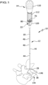
- a medical drilling device further developed as proposed makes it possible, in particular, to open the bone during a minimally invasive procedure, whereby the drill does not need to be removed to insert a K-wire. Rather, it is sufficient to remove the stylet from the longitudinal canal.
- the stylet which completely or almost completely fills the longitudinal canal, in particular with a form-fitting fit, prevents bone substance from penetrating the longitudinal canal.
- the longitudinal canal of the drill is then completely free of bone substance, so that the drill itself can be used as a guide for a K-wire in order to place it in the bone, for example, a vertebra, in a defined manner, i.e., in a specific position and with a specific orientation.
- the stylet thus forms, in particular, a closure element in the form of a plug. for the longitudinal canal to prevent bone substance or other tissue from penetrating and blocking the longitudinal canal during drilling.
- the drill bit does not need to be removed before inserting the K-wire, as is the case with conventional procedures, but rather serves as a guide for the K-wire. This simplifies the location of the entry point on the bone when inserting the K-wire, thus also facilitating the handling of the drilling device. This particularly improves the quality of the surgical procedure. Furthermore, this also reduces the operating time.
- the drilling device coupling section is rotationally asymmetrical with respect to the longitudinal axis. This allows the drilling device to be coupled in a defined manner to a handle or a drill, for example, a drill chuck or a coupling of the latter. In particular, this allows a rotationally fixed coupling between the handle or the drill chuck and the drilling device to be easily realized.
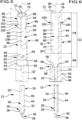
- the drill coupling section has at least one drill driving surface
- the proximal stylet section has at least one stylet driving surface
- the at least one drill driving surface and the at least one stylet driving surface abut one another or substantially abut one another in the drilling position.
- said surfaces run parallel to the longitudinal axis, they make it possible to engage the drill around the stylet in the region of the drilling device coupling section in such a way that the stylet rotates when the drill rotates. In other words, the drill and the stylet are rotated together in this way.
- the proximal stylet section and the drill coupling section mutually form drivers in order to transmit torques to the other component, in particular depending on which component the torques are applied to by the handle or the drilling machine.
- Good coupling and guidance of the stylet and drill can be achieved in particular by having the drill coupling section with two drill driving surfaces and by having the proximal stylet section with two stylet driving surfaces.
- the two driving surfaces can be designed to run parallel to each other in pairs.
- the two stylet driving surfaces can point away from each other in opposite directions, while the two drill driving surfaces can point towards each other.
- the longitudinal channel preferably has an oval cross-section.
- the cross-section can be circular.
- An oval cross-section has the additional advantage that the stylet is forced to rotate with the drill.
- a circular cross-section is advantageous because it allows a K-wire with a circular cross-section to be guided through the longitudinal channel in a defined manner and also twisted within it.
- the distal stylet section has a cross-section that corresponds to the cross-section of the longitudinal canal. This makes it particularly possible to fill the longitudinal canal with the distal stylet section in a form-fitting manner. This can easily and safely prevent the penetration of bone substance into the longitudinal canal.
- a tip is formed at the distal end of the distal stylet section. This tip allows the drill to be easily positioned on a bone. In particular, slippage of the drill tip can be easily and safely prevented.
- a distal end of the distal stylet section in the drilling position, reaches up to a distal end of the stylet channel or protrudes beyond it.
- the longitudinal channel is sufficiently closed on the distal side to prevent the penetration, in particular of bone tissue, when drilling into a bone.
- the distal stylet section protrudes beyond the distal end of the longitudinal channel, it can be used, for example, to position the drill on the bone.
- the distal end of the distal stylet section is preferably designed in the shape of a point for this purpose.
- the medical drilling device can be easily configured if the drilling device coupling section is mirror-symmetrical to a mirror plane containing the longitudinal axis.
- a drilling device coupling section with a non-circular cross-section can be formed in this way.
- the design of the medical drilling device can be simplified if the drill coupling section and the proximal stylet section are each mirror-symmetrical to the mirror plane.
- the proximal stylet section and the drill coupling section can be transformed into themselves by the mirror plane.
- Such a design enables, in particular, the formation of a drill coupling section with a slot for receiving the proximal stylet section.
- the slot is then preferably also mirror-symmetrical to the mirror plane.
- the at least one stylet driving surface and the at least one drill driving surface run parallel to the mirror plane.
- the stylet with the distal stylet section can be brought into the drilling position, starting from a separation position in which the stylet and the drill are disengaged, by inserting the distal stylet section into the longitudinal channel starting from its proximal end.
- This configuration enables, in particular, the coupling of the stylet with the drill in a simple manner. This is particularly advantageous when, during a surgical procedure, several pedicle screws are to be inserted in the initially described After the K-wire has been inserted, the cannulated drill can be removed. The stylet can then be re-engaged with the drill in the manner described above to close the drill's longitudinal channel.
- only one drill with an associated stylet is required for such a procedure, thus requiring only a single drilling device.
- a depth stop for the stylet is arranged or designed on the drill to limit the insertion depth of the distal stylet section into the longitudinal canal. This ensures, in particular, that the stylet fills the longitudinal canal as desired. To do this, the user only needs to insert the stylet into the longitudinal canal up to the depth stop. If the stylet cannot be moved any further in the distal direction relative to the drill, the stylet has reached the desired position.
- the drilling device can be designed in a simple manner if the depth stop comprises a stop surface of the drill pointing in the proximal direction, against which the proximal stylet section rests on the distal side in the drilling position.
- the stop surface extends transversely, in particular perpendicularly, to the longitudinal axis. This allows a depth stop to be easily implemented.
- the stop surface is adjacent to a proximal insertion opening of the longitudinal channel and at least partially, in particular completely, surrounds it.
- Such a configuration makes it possible, in particular, to design the distal stylet section exclusively to correspond to the longitudinal channel in order to fill the longitudinal channel in the drilling position.
- the proximal stylet section can then exclusively form part of the drilling device coupling section.
- deformation, In particular, kinking of the distal stylet section relative to the proximal stylet section can be easily prevented.
- the drill coupling section comprises a coupling slot extending parallel to the longitudinal axis, and if the proximal stylet section engages the coupling slot in the drilling position.
- This configuration enables, in particular, simple and defined relative positioning of the proximal stylet section and the drill coupling section.
- the proximal stylet section can be guided through the drill coupling section on both sides.
- the coupling slot has two facing slot surfaces, and if the two slot surfaces form the two drill driving surfaces.
- the two slot surfaces can be parallel to each other and parallel to the mirror plane described above.
- the mirror plane can contain the longitudinal axis or run parallel to it.
- a rotationally asymmetrical drilling device coupling section can be formed in a simple manner, in particular by having the drilling device coupling section have a coupling surface that extends parallel to the longitudinal axis and transversely, in particular perpendicularly, to the at least one drill driving surface.
- this coupling surface can be formed as part of a drilling device coupling section that is otherwise rotationally symmetrically shaped.
- the coupling surface is flat or substantially flat and comprises at least two coupling surface sections, if at least one of the at least two coupling surface sections is formed by a side surface of the drill coupling section and if at least one further of the at least two coupling surface sections is formed by a side surface of the proximal stylet section.
- this makes it possible to transmit torque not only to the drill bit but also to the stylet when coupling the drill coupling section to a handle for the drill bit or a power drill. This prevents, in particular, twisting of the proximal stylet section and the distal stylet section relative to each other.
- a coupling surface can be formed in a simple manner if the drilling device coupling section has a rotationally symmetrical basic shape and a lateral flattening extending parallel to the longitudinal axis.
- the flattened portion encompasses the coupling surface.
- Such a configuration enables, in particular, simple and secure engagement of the drilling device with a handle or a drill, for example, in a rotationally fixed manner.
- the drill coupling section and the proximal stylet section can each be rotationally asymmetrical with respect to the longitudinal axis. This allows the two sections mentioned to be easily configured as drivers for the other section in order to transmit torque.
- At least one coupling element is arranged or configured on the drilling device coupling section to specify an axial position of the drilling device and a handle or a drill relative to one another.
- the at least one coupling element makes it possible, in particular, to prevent a relative movement in the axial direction between the drilling device and the handle or the drill in a coupling position.
- a handle or a drill can be easily coupled to the drilling device if the at least one coupling element is designed to point in the radial direction.
- the at least one coupling element can be designed in the form of a recess pointing in the radial direction, for example in the form of an annular groove or a section of an annular groove relative to the longitudinal axis.
- Coupling the drilling device and the handle or drill can be further simplified if the at least one coupling element is designed in the form of a coupling projection or a coupling receptacle.
- Such coupling elements can be force- and/or positively engaged with corresponding coupling elements on the handle or drill.
- the at least one coupling element is configured to at least partially surround the longitudinal axis.
- an annular groove can be formed in this way that extends over a circumferential angle of less than 360° with respect to the longitudinal axis.
- a coupling surface is configured on the drilling device coupling section as described above, whereby the drilling device coupling section is given a non-circular cross-section, it is not necessary for the at least one coupling element to extend over a full circumference with respect to the longitudinal axis, but only over a portion of the circumference, for example, only over an angular range of 180° or 270°.
- the at least one coupling element is interrupted by the flattened portion.
- this can be achieved, for example, by dimensioning the flattened portion such that, in an originally rotationally symmetrical drilling device coupling section with a coupling element that rotates around the longitudinal axis, and indeed completely around the longitudinal axis, the coupling element is completely removed in the area of the flattened portion.
- At least one handling element is arranged or formed on the proximal stylet section.
- a handling element can in particular be used to be engaged with a finger or a corresponding pulling element in order to move the stylet relative to the drill in the proximal or distal direction.
- a pulling element corresponding to the at least one handling element on a handle or a drill chuck of a drill, which pulling element can be specifically engaged or disengaged from the at least one handling element in order to move the stylet relative to the drill in the distal or, in particular, in the proximal direction, as described.
- the stylet can thus be easily pulled out of the drill in the proximal direction.
- the handling element is designed in the form of a handling recess or a handling projection.
- the handling element can be formed by a part of the at least one coupling element, which part is formed on the proximal stylet section. This further simplifies the design of the drilling device.
- the at least one handling element is designed to point radially relative to the longitudinal axis.
- the at least one handling element can be designed as part of a groove on the drilling device coupling section that extends circumferentially relative to the longitudinal axis.
- the handling of the drilling device can be further simplified if, in the drilling position, it has an end surface that runs transversely, particularly perpendicularly, to the longitudinal axis. In particular, this can indicate whether the The stylet is engaged with the drill in the desired manner, i.e. in particular the distal stylet section fills the longitudinal channel of the drill.
- proximal stylet section defines a proximal stylet end surface
- drill coupling section defines a proximal drill end surface
- end surface is formed partly by the stylet end surface and partly by the drill end surface.
- the end surface can thus serve as a type of visual indicator for the user.
- the drill bit is made of a metallic material.
- it can be made of stainless steel or titanium.
- the stylet is made of a metallic material or plastic.
- a plastic stylet is particularly cost-effective to manufacture.
- a metallic stylet can also effectively dissipate heat generated during drilling, in addition to the drill bit.
- the drilling device is made of at least one sterilizable material.
- it can be made of only one sterilizable material.
- the stylet and the drill can be made of the same material.
- the object stated at the outset is further achieved according to the invention in a drilling system of the type described at the outset in that the medical drilling device is designed in the form of one of the advantageous embodiments of drilling devices described above and that the drilling system comprises a handle and/or a drilling machine for rotationally fixed coupling to the medical drilling device.
- the drilling device can be manipulated as desired using the handle or drill, particularly for drilling into a bone, for example, to insert a K-wire as a guide for a pedicle screw.
- the drilling system can also comprise multiple drilling devices that differ in shape and size.
- the drilling system can include different types of drill bits, such as twist drills, crown drills, reamers, center drills, or countersink drills.
- the drilling system advantageously comprises at least one K-wire.
- a K-wire within the meaning of this application is a drill wire. These terms are therefore used synonymously.
- it can also comprise a plurality of K-wires, for example with different diameters and lengths.
- the K-wire can be inserted through the longitudinal channel into the bone opened with the drilling device after removal of the stylet. For this purpose, it must be long enough to allow the drill to be withdrawn. After removing the drill by pulling it proximally over the K-wire, a cannulated pedicle screw can then be pushed distally over the K-wire and guided towards the bone and screwed into it.
- the K-wire is preferably longer than the drill to ensure guided removal.
- the handle or the drill can be easily coupled to the drilling device if the handle and/or the drill comprise a coupling device for force-locking and/or form-locking coupling to the drilling device coupling section in a coupling position.
- the coupling device can be moved from the coupling position to a release position, in which it is disengaged from the drilling device coupling section. In the release position, the drilling device can then be easily and safely removed from the handle or the drilling machine.
- the coupling device comprises a pulling element for engaging with the at least one handling element when the coupling device assumes the release position.
- the stylet can thus be removed from the drill in a simple and safe manner.
- the coupling device only has to be moved into the release position and the pulling element engaged with the at least one handling element. If the handle or the drill is withdrawn from the drilling device in the described position, they remain coupled to the stylet but are disengaged from the drill, so that when withdrawn in the proximal direction they pull the stylet out of the longitudinal channel of the drill.
Landscapes
- Health & Medical Sciences (AREA)
- Surgery (AREA)
- Life Sciences & Earth Sciences (AREA)
- Biomedical Technology (AREA)
- Medical Informatics (AREA)
- Orthopedic Medicine & Surgery (AREA)
- Oral & Maxillofacial Surgery (AREA)
- Engineering & Computer Science (AREA)
- Dentistry (AREA)
- Heart & Thoracic Surgery (AREA)
- Nuclear Medicine, Radiotherapy & Molecular Imaging (AREA)
- Molecular Biology (AREA)
- Animal Behavior & Ethology (AREA)
- General Health & Medical Sciences (AREA)
- Public Health (AREA)
- Veterinary Medicine (AREA)
- Surgical Instruments (AREA)
Applications Claiming Priority (2)
| Application Number | Priority Date | Filing Date | Title |
|---|---|---|---|
| DE102022104674.5A DE102022104674A1 (de) | 2022-02-28 | 2022-02-28 | Medizinische Bohrvorrichtung und medizinisches Bohrsystem |
| PCT/EP2023/054780 WO2023161460A1 (de) | 2022-02-28 | 2023-02-27 | Medizinische bohrvorrichtung und medizinisches bohrsystem |
Publications (2)
| Publication Number | Publication Date |
|---|---|
| EP4267019A1 EP4267019A1 (de) | 2023-11-01 |
| EP4267019B1 true EP4267019B1 (de) | 2025-04-02 |
Family
ID=85384421
Family Applications (1)
| Application Number | Title | Priority Date | Filing Date |
|---|---|---|---|
| EP23707719.3A Active EP4267019B1 (de) | 2022-02-28 | 2023-02-27 | Medizinische bohrvorrichtung und medizinisches bohrsystem |
Country Status (7)
| Country | Link |
|---|---|
| US (1) | US20240415525A1 (https=) |
| EP (1) | EP4267019B1 (https=) |
| JP (1) | JP2025506859A (https=) |
| CN (1) | CN118765180B (https=) |
| DE (1) | DE102022104674A1 (https=) |
| ES (1) | ES3032236T3 (https=) |
| WO (1) | WO2023161460A1 (https=) |
Families Citing this family (1)
| Publication number | Priority date | Publication date | Assignee | Title |
|---|---|---|---|---|
| DE102023121252B3 (de) * | 2023-08-09 | 2024-11-07 | B. Braun New Ventures GmbH | Medizinisches Schnellkupplungssystem zur werkzeuglosen Aufnahme einer Führungshülse |
Family Cites Families (23)
| Publication number | Priority date | Publication date | Assignee | Title |
|---|---|---|---|---|
| US5372583A (en) * | 1992-11-25 | 1994-12-13 | Cardiopulmonary Specialities, Inc. | Bone marrow infuser and method of use |
| EP0683651B1 (en) * | 1993-02-10 | 1999-09-29 | Sulzer Spine-Tech Inc. | Spinal stabilization surgical tool set |
| EP0700272B1 (en) * | 1993-05-27 | 1999-01-07 | Howmedica Inc. | Flexible medullary reaming system |
| GB9823305D0 (en) | 1998-10-23 | 1998-12-23 | Benoist Girard & Cie | A surgical trephine |
| US7544196B2 (en) * | 2001-02-20 | 2009-06-09 | Orthovita, Inc. | System and kit for delivery of restorative materials |
| BR0318151A (pt) | 2003-03-07 | 2006-02-21 | Synthes Ag | parafuso de travamento para uma garra intramedular |
| EP1691848B1 (en) * | 2003-10-23 | 2012-08-22 | TRANS1, Inc. | Tools and tool kits for performing minimally invasive procedures on the spine |
| US9381024B2 (en) * | 2005-07-31 | 2016-07-05 | DePuy Synthes Products, Inc. | Marked tools |
| WO2007093192A1 (en) | 2006-02-16 | 2007-08-23 | Universite Libre De Bruxelles | Surgical boring tool set |
| US8167899B2 (en) * | 2006-05-04 | 2012-05-01 | Warsaw Orthopedic, Inc. | Retractable stylet and cannula combination |
| US20080154304A1 (en) * | 2006-12-21 | 2008-06-26 | Arthrocare Corporation | System and method for accessing a tissue structure |
| US20090024129A1 (en) * | 2007-07-19 | 2009-01-22 | Jeremy Gordon | Perforator with inner and outer drills and a drive head, the inner drill configured to move against the outer drill in order to disengage from the drive head |
| DE502008002620D1 (de) * | 2008-08-04 | 2011-03-31 | Brainlab Ag | Klemmhülse zum Klemmen eines kanülierten Bohrers und eines Führungsdrahtes |
| JP6271592B2 (ja) * | 2013-02-13 | 2018-01-31 | シンセス・ゲーエムベーハーSynthes GmbH | ガイドワイヤー捕捉システムを具備する椎弓根スクリューに係合する制御器具 |
| US9028464B2 (en) * | 2013-03-08 | 2015-05-12 | Kyphon Saul | Bone fracture reduction system and methods of using the same |
| EP2997913A1 (en) * | 2014-09-18 | 2016-03-23 | AprioMed AB | Medical device |
| US11064980B2 (en) * | 2016-08-18 | 2021-07-20 | Lenkbar, Llc | Flexible tissue collection device |
| EP3694427A1 (en) * | 2017-10-12 | 2020-08-19 | Boston Scientific Limited | Locking assembly for medical device |
| CN109288553B (zh) * | 2018-09-13 | 2021-06-15 | 赵斌 | 医疗用骨科打孔器 |
| EP3730079B1 (en) * | 2019-03-06 | 2023-08-30 | K2M, Inc. | Bone screws and instrumentation |
| US11759280B2 (en) * | 2020-02-06 | 2023-09-19 | Aesculap Ag | Surgical instrumentation for fixation of cervical spine |
| US11439432B2 (en) * | 2020-04-09 | 2022-09-13 | Spinal Generations, Llc | Handle attachment for fluid delivery needle and method of use thereof |
| CN113693671A (zh) * | 2021-09-07 | 2021-11-26 | 胡效坤 | 一种颅骨钻孔用复合钻头以及使用方法 |
-
2022
- 2022-02-28 DE DE102022104674.5A patent/DE102022104674A1/de active Pending
-
2023
- 2023-02-27 EP EP23707719.3A patent/EP4267019B1/de active Active
- 2023-02-27 WO PCT/EP2023/054780 patent/WO2023161460A1/de not_active Ceased
- 2023-02-27 JP JP2024550684A patent/JP2025506859A/ja active Pending
- 2023-02-27 ES ES23707719T patent/ES3032236T3/es active Active
- 2023-02-27 CN CN202380023714.1A patent/CN118765180B/zh active Active
-
2024
- 2024-08-27 US US18/816,073 patent/US20240415525A1/en active Pending
Also Published As
| Publication number | Publication date |
|---|---|
| CN118765180A (zh) | 2024-10-11 |
| DE102022104674A1 (de) | 2023-08-31 |
| CN118765180B (zh) | 2025-12-26 |
| WO2023161460A1 (de) | 2023-08-31 |
| US20240415525A1 (en) | 2024-12-19 |
| EP4267019A1 (de) | 2023-11-01 |
| JP2025506859A (ja) | 2025-03-13 |
| ES3032236T3 (en) | 2025-07-16 |
Similar Documents
| Publication | Publication Date | Title |
|---|---|---|
| EP2692304B1 (de) | Chirurgisches Instrumentarium | |
| DE3852282T2 (de) | Intramedulläre, intertrochanterische Bruchfixierungsvorrichtung sowie Montagevorrichtung. | |
| EP2976031B1 (de) | Wirbelsäulenstabilisierungssystem und chirurgisches befestigungselement für ein wirbelsäulenstabilisierungssystem | |
| DE102012008970B3 (de) | Chirurgische Werkzeugeinrichtung | |
| DE2609723A1 (de) | Knochennagel | |
| DE102014109200A1 (de) | Medizinischer Schraubendreher, Schaft für den medizinischen Schraubendreher und Verfahren zum Einbringen von Pedikelschrauben | |
| EP0522125B1 (de) | Zervix-stanze | |
| EP2266483A1 (de) | Chirurgische Knochenverankerungsvorrichtung und Wirbelsäulenfixationssystem | |
| EP0736286A2 (de) | Osteosynthese-Hilfsmittel zur Versorgung subtrochanterer, pertrochanterer und Schenkelhalsfrakturen | |
| WO1995009569A1 (de) | Bohrabschnitt, sowie mit einem derartigen bohrabschnitt versehene kirschnerdrähte, knochenfräser od. dgl. | |
| EP0682917A1 (de) | Schraube zum Zusammenhalten von zwei Knochenfragmenten und Chirurgieinstrumentarium zum Einsetzen der Schraube | |
| WO2006069453A1 (de) | Marknagel | |
| WO2002011629A1 (de) | Vorrichtung zum einführen von medizinischen mitteln | |
| EP4171409B1 (de) | Werkzeugansatzstelle mit ausrichthilfe für schraubenelemente | |
| EP4267019B1 (de) | Medizinische bohrvorrichtung und medizinisches bohrsystem | |
| EP1720473B1 (de) | Knochenfixierungsmittel | |
| DE102005032197B4 (de) | Endoskopisches Instrument | |
| WO1993022975A1 (de) | Zielgerät für das setzen von pedikelschrauben in einem wirbelkörper | |
| EP1587434B1 (de) | Medizinisches instrument zum präparieren von gewebe | |
| DE202021105388U1 (de) | Endoskopisches Instrumentarium für die Bandscheibenchirurgie | |
| DE2542263A1 (de) | Marknagel fuer die osteosynthese bei frakturen von roehrenknochen | |
| DE202004001504U1 (de) | Vorrichtung zum Einspannen von Knochenfixationsmitteln | |
| EP2422752A1 (de) | Implantantat-System für die Fusion von Wirbelkörpern | |
| EP2945562B1 (de) | Schaft eines dentalwerkzeugs | |
| WO2005053548A1 (de) | Vorrichtung zur reposition von knochenfrakturen |
Legal Events
| Date | Code | Title | Description |
|---|---|---|---|
| STAA | Information on the status of an ep patent application or granted ep patent |
Free format text: STATUS: UNKNOWN |
|
| STAA | Information on the status of an ep patent application or granted ep patent |
Free format text: STATUS: THE INTERNATIONAL PUBLICATION HAS BEEN MADE |
|
| PUAI | Public reference made under article 153(3) epc to a published international application that has entered the european phase |
Free format text: ORIGINAL CODE: 0009012 |
|
| STAA | Information on the status of an ep patent application or granted ep patent |
Free format text: STATUS: REQUEST FOR EXAMINATION WAS MADE |
|
| 17P | Request for examination filed |
Effective date: 20230727 |
|
| AK | Designated contracting states |
Kind code of ref document: A1 Designated state(s): AL AT BE BG CH CY CZ DE DK EE ES FI FR GB GR HR HU IE IS IT LI LT LU LV MC ME MK MT NL NO PL PT RO RS SE SI SK SM TR |
|
| GRAP | Despatch of communication of intention to grant a patent |
Free format text: ORIGINAL CODE: EPIDOSNIGR1 |
|
| STAA | Information on the status of an ep patent application or granted ep patent |
Free format text: STATUS: GRANT OF PATENT IS INTENDED |
|
| RIC1 | Information provided on ipc code assigned before grant |
Ipc: A61B 17/84 20060101ALN20240828BHEP Ipc: A61B 17/16 20060101AFI20240828BHEP |
|
| DAV | Request for validation of the european patent (deleted) | ||
| DAX | Request for extension of the european patent (deleted) | ||
| INTG | Intention to grant announced |
Effective date: 20240919 |
|
| GRAJ | Information related to disapproval of communication of intention to grant by the applicant or resumption of examination proceedings by the epo deleted |
Free format text: ORIGINAL CODE: EPIDOSDIGR1 |
|
| STAA | Information on the status of an ep patent application or granted ep patent |
Free format text: STATUS: REQUEST FOR EXAMINATION WAS MADE |
|
| GRAP | Despatch of communication of intention to grant a patent |
Free format text: ORIGINAL CODE: EPIDOSNIGR1 |
|
| STAA | Information on the status of an ep patent application or granted ep patent |
Free format text: STATUS: GRANT OF PATENT IS INTENDED |
|
| INTC | Intention to grant announced (deleted) | ||
| GRAS | Grant fee paid |
Free format text: ORIGINAL CODE: EPIDOSNIGR3 |
|
| RIC1 | Information provided on ipc code assigned before grant |
Ipc: A61B 17/84 20060101ALN20250115BHEP Ipc: A61B 17/16 20060101AFI20250115BHEP |
|
| INTG | Intention to grant announced |
Effective date: 20250124 |
|
| GRAA | (expected) grant |
Free format text: ORIGINAL CODE: 0009210 |
|
| STAA | Information on the status of an ep patent application or granted ep patent |
Free format text: STATUS: THE PATENT HAS BEEN GRANTED |
|
| AK | Designated contracting states |
Kind code of ref document: B1 Designated state(s): AL AT BE BG CH CY CZ DE DK EE ES FI FR GB GR HR HU IE IS IT LI LT LU LV MC ME MK MT NL NO PL PT RO RS SE SI SK SM TR |
|
| REG | Reference to a national code |
Ref country code: GB Ref legal event code: FG4D Free format text: NOT ENGLISH |
|
| REG | Reference to a national code |
Ref country code: CH Ref legal event code: EP |
|
| REG | Reference to a national code |
Ref country code: IE Ref legal event code: FG4D Free format text: LANGUAGE OF EP DOCUMENT: GERMAN |
|
| REG | Reference to a national code |
Ref country code: DE Ref legal event code: R096 Ref document number: 502023000785 Country of ref document: DE |
|
| P01 | Opt-out of the competence of the unified patent court (upc) registered |
Free format text: CASE NUMBER: APP_18419/2025 Effective date: 20250416 |
|
| REG | Reference to a national code |
Ref country code: ES Ref legal event code: FG2A Ref document number: 3032236 Country of ref document: ES Kind code of ref document: T3 Effective date: 20250716 |
|
| REG | Reference to a national code |
Ref country code: NL Ref legal event code: MP Effective date: 20250402 |
|
| PG25 | Lapsed in a contracting state [announced via postgrant information from national office to epo] |
Ref country code: NL Free format text: LAPSE BECAUSE OF FAILURE TO SUBMIT A TRANSLATION OF THE DESCRIPTION OR TO PAY THE FEE WITHIN THE PRESCRIBED TIME-LIMIT Effective date: 20250402 |
|
| PG25 | Lapsed in a contracting state [announced via postgrant information from national office to epo] |
Ref country code: FI Free format text: LAPSE BECAUSE OF FAILURE TO SUBMIT A TRANSLATION OF THE DESCRIPTION OR TO PAY THE FEE WITHIN THE PRESCRIBED TIME-LIMIT Effective date: 20250402 Ref country code: PT Free format text: LAPSE BECAUSE OF FAILURE TO SUBMIT A TRANSLATION OF THE DESCRIPTION OR TO PAY THE FEE WITHIN THE PRESCRIBED TIME-LIMIT Effective date: 20250804 |
|
| REG | Reference to a national code |
Ref country code: LT Ref legal event code: MG9D |
|
| PG25 | Lapsed in a contracting state [announced via postgrant information from national office to epo] |
Ref country code: GR Free format text: LAPSE BECAUSE OF FAILURE TO SUBMIT A TRANSLATION OF THE DESCRIPTION OR TO PAY THE FEE WITHIN THE PRESCRIBED TIME-LIMIT Effective date: 20250703 Ref country code: NO Free format text: LAPSE BECAUSE OF FAILURE TO SUBMIT A TRANSLATION OF THE DESCRIPTION OR TO PAY THE FEE WITHIN THE PRESCRIBED TIME-LIMIT Effective date: 20250702 |
|
| PG25 | Lapsed in a contracting state [announced via postgrant information from national office to epo] |
Ref country code: PL Free format text: LAPSE BECAUSE OF FAILURE TO SUBMIT A TRANSLATION OF THE DESCRIPTION OR TO PAY THE FEE WITHIN THE PRESCRIBED TIME-LIMIT Effective date: 20250402 |
|
| PG25 | Lapsed in a contracting state [announced via postgrant information from national office to epo] |
Ref country code: BG Free format text: LAPSE BECAUSE OF FAILURE TO SUBMIT A TRANSLATION OF THE DESCRIPTION OR TO PAY THE FEE WITHIN THE PRESCRIBED TIME-LIMIT Effective date: 20250402 |
|
| PG25 | Lapsed in a contracting state [announced via postgrant information from national office to epo] |
Ref country code: HR Free format text: LAPSE BECAUSE OF FAILURE TO SUBMIT A TRANSLATION OF THE DESCRIPTION OR TO PAY THE FEE WITHIN THE PRESCRIBED TIME-LIMIT Effective date: 20250402 |
|
| PG25 | Lapsed in a contracting state [announced via postgrant information from national office to epo] |
Ref country code: RS Free format text: LAPSE BECAUSE OF FAILURE TO SUBMIT A TRANSLATION OF THE DESCRIPTION OR TO PAY THE FEE WITHIN THE PRESCRIBED TIME-LIMIT Effective date: 20250702 |
|
| PG25 | Lapsed in a contracting state [announced via postgrant information from national office to epo] |
Ref country code: IS Free format text: LAPSE BECAUSE OF FAILURE TO SUBMIT A TRANSLATION OF THE DESCRIPTION OR TO PAY THE FEE WITHIN THE PRESCRIBED TIME-LIMIT Effective date: 20250802 |
|
| PG25 | Lapsed in a contracting state [announced via postgrant information from national office to epo] |
Ref country code: LV Free format text: LAPSE BECAUSE OF FAILURE TO SUBMIT A TRANSLATION OF THE DESCRIPTION OR TO PAY THE FEE WITHIN THE PRESCRIBED TIME-LIMIT Effective date: 20250402 |
|
| REG | Reference to a national code |
Ref country code: DE Ref legal event code: R097 Ref document number: 502023000785 Country of ref document: DE |
|
| PG25 | Lapsed in a contracting state [announced via postgrant information from national office to epo] |
Ref country code: DK Free format text: LAPSE BECAUSE OF FAILURE TO SUBMIT A TRANSLATION OF THE DESCRIPTION OR TO PAY THE FEE WITHIN THE PRESCRIBED TIME-LIMIT Effective date: 20250402 Ref country code: SM Free format text: LAPSE BECAUSE OF FAILURE TO SUBMIT A TRANSLATION OF THE DESCRIPTION OR TO PAY THE FEE WITHIN THE PRESCRIBED TIME-LIMIT Effective date: 20250402 |
|
| PG25 | Lapsed in a contracting state [announced via postgrant information from national office to epo] |
Ref country code: CZ Free format text: LAPSE BECAUSE OF FAILURE TO SUBMIT A TRANSLATION OF THE DESCRIPTION OR TO PAY THE FEE WITHIN THE PRESCRIBED TIME-LIMIT Effective date: 20250402 |
|
| PG25 | Lapsed in a contracting state [announced via postgrant information from national office to epo] |
Ref country code: EE Free format text: LAPSE BECAUSE OF FAILURE TO SUBMIT A TRANSLATION OF THE DESCRIPTION OR TO PAY THE FEE WITHIN THE PRESCRIBED TIME-LIMIT Effective date: 20250402 |
|
| PG25 | Lapsed in a contracting state [announced via postgrant information from national office to epo] |
Ref country code: SK Free format text: LAPSE BECAUSE OF FAILURE TO SUBMIT A TRANSLATION OF THE DESCRIPTION OR TO PAY THE FEE WITHIN THE PRESCRIBED TIME-LIMIT Effective date: 20250402 |
|
| PLBE | No opposition filed within time limit |
Free format text: ORIGINAL CODE: 0009261 |
|
| STAA | Information on the status of an ep patent application or granted ep patent |
Free format text: STATUS: NO OPPOSITION FILED WITHIN TIME LIMIT |
|
| REG | Reference to a national code |
Ref country code: CH Ref legal event code: L10 Free format text: ST27 STATUS EVENT CODE: U-0-0-L10-L00 (AS PROVIDED BY THE NATIONAL OFFICE) Effective date: 20260211 |
|
| REG | Reference to a national code |
Ref country code: CH Ref legal event code: U11 Free format text: ST27 STATUS EVENT CODE: U-0-0-U10-U11 (AS PROVIDED BY THE NATIONAL OFFICE) Effective date: 20260301 |
|
| 26N | No opposition filed |
Effective date: 20260105 |
|
| PGFP | Annual fee paid to national office [announced via postgrant information from national office to epo] |
Ref country code: ES Payment date: 20260319 Year of fee payment: 4 |
|
| PGFP | Annual fee paid to national office [announced via postgrant information from national office to epo] |
Ref country code: DE Payment date: 20260217 Year of fee payment: 4 |
|
| PGFP | Annual fee paid to national office [announced via postgrant information from national office to epo] |
Ref country code: AT Payment date: 20260301 Year of fee payment: 4 |
|
| PGFP | Annual fee paid to national office [announced via postgrant information from national office to epo] |
Ref country code: IT Payment date: 20260228 Year of fee payment: 4 |
|
| PGFP | Annual fee paid to national office [announced via postgrant information from national office to epo] |
Ref country code: FR Payment date: 20260219 Year of fee payment: 4 |
|
| PGFP | Annual fee paid to national office [announced via postgrant information from national office to epo] |
Ref country code: CH Payment date: 20260301 Year of fee payment: 4 |