EP4266435A1 - Humidificateur à membrane de pile à combustible - Google Patents
Humidificateur à membrane de pile à combustible Download PDFInfo
- Publication number
- EP4266435A1 EP4266435A1 EP22750100.4A EP22750100A EP4266435A1 EP 4266435 A1 EP4266435 A1 EP 4266435A1 EP 22750100 A EP22750100 A EP 22750100A EP 4266435 A1 EP4266435 A1 EP 4266435A1
- Authority
- EP
- European Patent Office
- Prior art keywords
- fuel cell
- middle case
- hollow fiber
- sliding member
- partition wall
- Prior art date
- Legal status (The legal status is an assumption and is not a legal conclusion. Google has not performed a legal analysis and makes no representation as to the accuracy of the status listed.)
- Pending
Links
- 239000000446 fuel Substances 0.000 title claims abstract description 79
- 210000000170 cell membrane Anatomy 0.000 title claims abstract description 41
- 239000012528 membrane Substances 0.000 claims abstract description 126
- 239000012510 hollow fiber Substances 0.000 claims abstract description 87
- 210000004027 cell Anatomy 0.000 claims abstract description 40
- 238000003780 insertion Methods 0.000 claims abstract description 29
- 230000037431 insertion Effects 0.000 claims abstract description 29
- 238000005192 partition Methods 0.000 claims description 62
- 230000007423 decrease Effects 0.000 abstract description 7
- 239000012530 fluid Substances 0.000 description 91
- 230000002159 abnormal effect Effects 0.000 description 17
- 239000005518 polymer electrolyte Substances 0.000 description 9
- 238000004382 potting Methods 0.000 description 8
- 239000007789 gas Substances 0.000 description 6
- UFHFLCQGNIYNRP-UHFFFAOYSA-N Hydrogen Chemical compound [H][H] UFHFLCQGNIYNRP-UHFFFAOYSA-N 0.000 description 3
- QVGXLLKOCUKJST-UHFFFAOYSA-N atomic oxygen Chemical compound [O] QVGXLLKOCUKJST-UHFFFAOYSA-N 0.000 description 3
- 239000001257 hydrogen Substances 0.000 description 3
- 229910052739 hydrogen Inorganic materials 0.000 description 3
- 239000000463 material Substances 0.000 description 3
- 239000001301 oxygen Substances 0.000 description 3
- 229910052760 oxygen Inorganic materials 0.000 description 3
- 238000010248 power generation Methods 0.000 description 3
- XLYOFNOQVPJJNP-UHFFFAOYSA-N water Substances O XLYOFNOQVPJJNP-UHFFFAOYSA-N 0.000 description 3
- NBIIXXVUZAFLBC-UHFFFAOYSA-N Phosphoric acid Chemical compound OP(O)(O)=O NBIIXXVUZAFLBC-UHFFFAOYSA-N 0.000 description 2
- 239000004642 Polyimide Substances 0.000 description 2
- 230000008878 coupling Effects 0.000 description 2
- 238000010168 coupling process Methods 0.000 description 2
- 238000005859 coupling reaction Methods 0.000 description 2
- 230000005611 electricity Effects 0.000 description 2
- 239000003792 electrolyte Substances 0.000 description 2
- 229920002492 poly(sulfone) Polymers 0.000 description 2
- 229920001721 polyimide Polymers 0.000 description 2
- 239000000126 substance Substances 0.000 description 2
- BVKZGUZCCUSVTD-UHFFFAOYSA-L Carbonate Chemical compound [O-]C([O-])=O BVKZGUZCCUSVTD-UHFFFAOYSA-L 0.000 description 1
- 229920000557 Nafion® Polymers 0.000 description 1
- 229920012266 Poly(ether sulfone) PES Polymers 0.000 description 1
- 239000004697 Polyetherimide Substances 0.000 description 1
- 229920000491 Polyphenylsulfone Polymers 0.000 description 1
- 229910000147 aluminium phosphate Inorganic materials 0.000 description 1
- 239000003054 catalyst Substances 0.000 description 1
- 238000006243 chemical reaction Methods 0.000 description 1
- 238000002485 combustion reaction Methods 0.000 description 1
- 238000012217 deletion Methods 0.000 description 1
- 230000037430 deletion Effects 0.000 description 1
- 238000010586 diagram Methods 0.000 description 1
- 230000000694 effects Effects 0.000 description 1
- 238000005265 energy consumption Methods 0.000 description 1
- 239000003344 environmental pollutant Substances 0.000 description 1
- 238000002347 injection Methods 0.000 description 1
- 239000007924 injection Substances 0.000 description 1
- 230000010354 integration Effects 0.000 description 1
- 239000002184 metal Substances 0.000 description 1
- 238000000034 method Methods 0.000 description 1
- 239000012466 permeate Substances 0.000 description 1
- 239000004033 plastic Substances 0.000 description 1
- 229920003023 plastic Polymers 0.000 description 1
- 231100000719 pollutant Toxicity 0.000 description 1
- 239000004417 polycarbonate Substances 0.000 description 1
- 229920000515 polycarbonate Polymers 0.000 description 1
- 229920001601 polyetherimide Polymers 0.000 description 1
- 229920000642 polymer Polymers 0.000 description 1
- 230000036647 reaction Effects 0.000 description 1
- 239000011347 resin Substances 0.000 description 1
- 229920005989 resin Polymers 0.000 description 1
- 238000000926 separation method Methods 0.000 description 1
- 239000007787 solid Substances 0.000 description 1
- 239000000243 solution Substances 0.000 description 1
- 238000006467 substitution reaction Methods 0.000 description 1
Images


Classifications
-
- H—ELECTRICITY
- H01—ELECTRIC ELEMENTS
- H01M—PROCESSES OR MEANS, e.g. BATTERIES, FOR THE DIRECT CONVERSION OF CHEMICAL ENERGY INTO ELECTRICAL ENERGY
- H01M8/00—Fuel cells; Manufacture thereof
- H01M8/04—Auxiliary arrangements, e.g. for control of pressure or for circulation of fluids
- H01M8/04082—Arrangements for control of reactant parameters, e.g. pressure or concentration
- H01M8/04089—Arrangements for control of reactant parameters, e.g. pressure or concentration of gaseous reactants
- H01M8/04119—Arrangements for control of reactant parameters, e.g. pressure or concentration of gaseous reactants with simultaneous supply or evacuation of electrolyte; Humidifying or dehumidifying
- H01M8/04126—Humidifying
- H01M8/04149—Humidifying by diffusion, e.g. making use of membranes
-
- B—PERFORMING OPERATIONS; TRANSPORTING
- B01—PHYSICAL OR CHEMICAL PROCESSES OR APPARATUS IN GENERAL
- B01D—SEPARATION
- B01D63/00—Apparatus in general for separation processes using semi-permeable membranes
- B01D63/02—Hollow fibre modules
- B01D63/04—Hollow fibre modules comprising multiple hollow fibre assemblies
- B01D63/043—Hollow fibre modules comprising multiple hollow fibre assemblies with separate tube sheets
-
- H—ELECTRICITY
- H01—ELECTRIC ELEMENTS
- H01M—PROCESSES OR MEANS, e.g. BATTERIES, FOR THE DIRECT CONVERSION OF CHEMICAL ENERGY INTO ELECTRICAL ENERGY
- H01M8/00—Fuel cells; Manufacture thereof
- H01M8/04—Auxiliary arrangements, e.g. for control of pressure or for circulation of fluids
- H01M8/04082—Arrangements for control of reactant parameters, e.g. pressure or concentration
- H01M8/04089—Arrangements for control of reactant parameters, e.g. pressure or concentration of gaseous reactants
- H01M8/04119—Arrangements for control of reactant parameters, e.g. pressure or concentration of gaseous reactants with simultaneous supply or evacuation of electrolyte; Humidifying or dehumidifying
- H01M8/04126—Humidifying
- H01M8/04141—Humidifying by water containing exhaust gases
-
- B—PERFORMING OPERATIONS; TRANSPORTING
- B01—PHYSICAL OR CHEMICAL PROCESSES OR APPARATUS IN GENERAL
- B01D—SEPARATION
- B01D2313/00—Details relating to membrane modules or apparatus
- B01D2313/23—Specific membrane protectors, e.g. sleeves or screens
-
- Y—GENERAL TAGGING OF NEW TECHNOLOGICAL DEVELOPMENTS; GENERAL TAGGING OF CROSS-SECTIONAL TECHNOLOGIES SPANNING OVER SEVERAL SECTIONS OF THE IPC; TECHNICAL SUBJECTS COVERED BY FORMER USPC CROSS-REFERENCE ART COLLECTIONS [XRACs] AND DIGESTS
- Y02—TECHNOLOGIES OR APPLICATIONS FOR MITIGATION OR ADAPTATION AGAINST CLIMATE CHANGE
- Y02E—REDUCTION OF GREENHOUSE GAS [GHG] EMISSIONS, RELATED TO ENERGY GENERATION, TRANSMISSION OR DISTRIBUTION
- Y02E60/00—Enabling technologies; Technologies with a potential or indirect contribution to GHG emissions mitigation
- Y02E60/30—Hydrogen technology
- Y02E60/50—Fuel cells
Definitions
- the present invention relates to a fuel cell membrane humidifier, and more particularly, to a fuel cell membrane humidifier capable of preventing humidification efficiency from being degraded due to a pressure difference between the inside and the outside of a membrane humidifier.
- Fuel cells are power generation cells that produce electricity through coupling between hydrogen and oxygen.
- the fuel cells have an advantage of being able to continuously produce electricity as long as the hydrogen and the oxygen are supplied, and having an efficiency that is about twice higher than an internal combustion engine because of no heat loss, unlike general chemical cells such as dry batteries or storage batteries.
- the fuel cells have an advantage of being environmentally friendly and being able to reduce concerns about resource depletion due to increased energy consumption.
- PEMFC polymer electrolyte membrane fuel cell
- PAFC phosphoric acid fuel cell
- MCFC molten carbonate fuel cell
- SOFC solid oxide fuel cell
- AFC alkaline fuel cell
- the polymer electrolyte membrane fuel cell is known to be the most promising not only for small-scale stationary power generation equipment but also for transportation systems because the polymer electrolyte membrane fuel cell operates at a lower temperature than other fuel cells and can be miniaturized due to a high output density.
- PEMFC polymer electrolyte membrane fuel cell
- Examples of a method for humidifying the polymer electrolyte membrane include 1) a bubbler humidification scheme for filling a pressure-resistant container with water and then passing a target gas through a diffuser to supply moisture, 2) a direct injection scheme for calculating a moisture supply amount required for a fuel cell reaction and directly supplying moisture to a gas flow pipe through a solenoid valve, and 3) a humidification membrane scheme for supplying moisture to a fluidized gas layer using a polymer separation membrane.
- the humidification membrane scheme for humidifying a polymer electrolyte membrane by providing water vapor to a gas supplied to the polymer electrolyte membrane using a membrane that selectively permeates only water vapor contained in an off-gas is advantageous in that a weight and size of a humidifier can be reduced.
- a selective permeable membrane used in the humidification membrane scheme is preferably a hollow fiber membrane having a large permeable area per unit volume when a module is formed. That is, when a membrane humidifier is manufactured using hollow fiber membranes, there are advantages that high integration of the hollow fiber membranes with a large contact surface area is possible so that a fuel cell can be sufficiently humidified even with a small capacity, low-cost materials can be used, and moisture and heat contained in an unreacted gas discharged with a high temperature from the fuel cell can be recovered and can be reused through the humidifier.
- FIGS. 1 , 2, and 3 are cross-sectional views of a fuel cell membrane humidifier of the related art.
- a hollow fiber membrane module 11 in which a plurality of hollow fiber membranes are accommodated is accommodated inside a middle case 10.
- the hollow fiber membrane module 11 may be formed in the form of a cartridge.
- a module insertion portion 12 into which the hollow fiber membrane module 11 in the form of a cartridge is inserted is formed inside the middle case 10.
- the module insertion portion 12 is formed of a plurality of partition walls 12a and 12b formed inside the middle case 10.
- the partition wall 12b forming an outer shell of the module insertion portion 12 is substantially a portion of an inner wall of the middle case 10.
- the hollow fiber membrane module 11 is inserted into the module insertion portion 12 by both sides of the hollow fiber membrane module 11 being put into the partition walls 12a and 12b.
- the middle case 10 includes a central recessed portion 10a of which a central portion is recessed, and an inner wall of the central recessed portion 10a and the hollow fiber membrane module 11 are tightly adhered to each other.
- two fluid flow spaces A and B formed by a non-recessed portion 10b of the middle case 10 and the hollow fiber membrane module 11 are isolated from each other.
- the central recessed portion 10a and the partition wall 12b forming the outer shell of the module insertion portion 12 are substantially the same.
- a second fluid discharged from a fuel cell stack flows into the inside through a fluid inlet (not illustrated) formed in the middle case 10 and flows through the hollow fiber membrane module 11 performs moisture exchange with a first fluid supplied from a blower and flowing inside the hollow fiber membranes.
- a cap case 20 is coupled to the middle case 10, and a fluid inlet 20a through which the first fluid flows into/from the inside is formed in the cap case 20.
- a pressure difference occurs between the inside and the outside of the membrane humidifier and the pressure of the second fluid flowing inside the membrane humidifier is higher than external atmospheric pressure, and thus, a pressure gradient is formed toward the outside of the membrane humidifier and a portion of the membrane humidifier (specifically, a recessed portion of the middle case) is deformed in a direction outside the membrane humidifier, as illustrated in FIG. 3 .
- the internal partition 12a since the internal partition 12a has the same pressure on both sides of the partition, a pressure gradient is not formed and deformation does not occur.
- the second fluid that does not flow through the hollow fiber membrane module 11 is a fluid that has not been humidified through the hollow fiber membranes, which causes a problem in that the humidification efficiency is degraded.
- FIG. 4 is a diagram illustrating another fuel cell membrane humidifier (see Korean Unexamined Patent Publication No. 2019-0138288 ) of the related art for solving the problems of the fuel cell membrane humidifier of the related art illustrated in FIG. 1 .
- a module insertion portion 12 and a pressure buffer portion 22 are formed inside a middle case 10.
- the pressure buffer portion 22 includes a space formed by an outer partition wall 12b and the middle case 10 spaced apart from each other, and a connection portion 21 formed between the outer partition wall 12b and the middle case 10.
- the connection portion 21 isolates a fluid flow space A from a fluid flow space B so that a fluid flowing into the inside through a fluid passage 20a flows only through a hollow fiber membrane cartridge C.
- the pressure buffer portion 22 configured as described above makes pressure on both sides of the outer partition wall 12b substantially the same. Since a pressure gradient is not formed on both the sides of the outer partition wall 12b due to the pressure buffer portion 22, the outer partition wall 12b is not deformed. Therefore, a gap is not created between the hollow fiber membrane cartridge C and the outer partition wall 12b, unlike the fuel cell membrane humidifier illustrated in FIG. 1 , making it possible to prevent the fluid in the fluid flow space A from flowing through the fluid flow space B instead of flowing through the hollow fiber membrane module, and as a result, to prevent the humidification efficiency from being degraded.
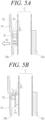
- the middle case 10 may receive an outward pressure and expand outward (indicated by E1) due to a pressure difference, as illustrated in FIG. 5A and 5B .
- E1 atmospheric pressure
- the outer partition wall 12b since the outer partition wall 12b is connected to the connection portion 21, the outer partition wall 12b may also expand outward (indicated by E2).
- An object of the present invention is to provide a fuel cell membrane humidifier capable of preventing the humidification efficiency from being degraded due to a pressure difference between the inside and the outside of the membrane humidifier.
- a fuel cell membrane humidifier of an embodiment of the invention includes a middle case having a module insertion portion formed therein; a cap case coupled to the middle case; a hollow fiber membrane module inserted into the module insertion portion; and an active pressure buffer formed between the middle case and the module insertion portion to prevent the module insertion portion from expanding due to a pressure difference between the inside and the outside of the middle case or eliminate a pressure difference, depending on an output situation of a fuel cell.
- the module insertion portion may include an outer partition wall formed to be spaced apart from an inner wall of the middle case, and the active pressure buffer portion may include a sliding structure formed between the outer partition wall and the inner wall of the middle case.
- the sliding structure may include a first sliding member formed to be fixed to the outer partition wall, protrude in a direction of the middle case, and be spaced apart from the inner wall of the middle case; and a second sliding member formed on the inner wall of the middle case and formed to protrude in a direction of the outer partition wall and be spaced apart from the outer partition wall.
- the fuel cell membrane humidifier of the embodiment of the present invention may include: a bypass hole formed in at least one of the first sliding member and the second sliding member, the bypass hole being able to be opened or closed depending on a magnitude of expansion pressure between the outer partition wall and the middle case.
- the first sliding member and the second sliding member may include sliding protrusions protruding in opposite directions.
- a sliding space may be formed between the sliding protrusion of the first sliding member and the sliding protrusion of the second sliding member.
- the second sliding member when the middle case expands outward, the second sliding member may expand outward together with the middle case, and the first sliding member may remain fixed to the outer partition wall.
- the hollow fiber membrane module may include at least one hollow fiber membrane bundle in which a plurality of hollow fiber membranes are integrated or at least one hollow fiber membrane cartridge in which a plurality of hollow fiber membranes are accommodated.
- the humidification efficiency it is possible to prevent the humidification efficiency from being degraded due to a pressure difference between the inside and the outside of the membrane humidifier. Further, it is possible to prevent a gap from being created between a hollow fiber membrane cartridge and an outer partition even in a high output situation or an abnormal output situation of a fuel cell to prevent the humidification efficiency from being degraded.
- FIGS. 6, 7 , 8 and 9 are views illustrating various types of fuel cell membrane humidifiers of an embodiment of the present invention.
- the fuel cell membrane humidifier hereinafter also referred to as a 'membrane humidifier'
- the fuel cell membrane humidifier includes a middle case 110 and a cap case 120.
- the middle case 110 is combined with the cap case 120 to form an outer shape of the membrane humidifier.
- the middle case 110 and the cap case 120 may be made of hard plastic such as polycarbonate or metal.
- the middle case 110 and the cap case 120 may have a polygonal cross-sectional shape in a width direction, as illustrated in FIGS. 6 and 7 .
- the polygon may be a quadrangle, a square, a trapezoid, a parallelogram, a pentagon, a hexagon, or the like, and the polygon may have a shape with rounded corners.
- the cross-sectional shape in the width direction may be a circular shape, as illustrated in FIGS. 8 and 9 .
- the circular shape may be an elliptical shape.
- FIGS. 6, 7 , 8 and 9 illustrate only examples of the shape of the membrane humidifier, but the present invention is not limited thereto.
- a second fluid inlet 111 through which the second fluid is supplied, and a second fluid outlet 112 through which the second fluid is discharged are formed, and a hollow fiber membrane module F in which a plurality of hollow fiber membranes are accommodated is disposed inside the middle case 110.
- reference sign 111 may denote the second fluid outlet through which the second fluid is discharged
- reference sign 112 may denote a second fluid inlet through which the second fluid is supplied. That is, one of reference signs 111 and 112 may denote the second fluid inlet, and the other may denote the second fluid outlet.
- reference sign 111 denotes the second fluid inlet and reference sign 112 denotes the second fluid outlet will be described, but the present invention is not limited thereto.
- the hollow fiber membrane module F may be a hollow fiber membrane bundle in which a plurality of hollow fiber membranes are integrated as illustrated in FIGS. 7 and 9 , or may be hollow fiber membrane cartridges in which hollow fiber membranes or hollow fiber membrane bundles are accommodated as illustrated in FIGS. 6 and 8 .
- a case in which a plurality of hollow fiber membrane cartridges form the hollow fiber membrane module F is illustrated in FIGS. 6 and 8 , the present invention is not limited thereto, and the hollow fiber membrane module F may be formed of one hollow fiber membrane cartridge.
- the hollow fiber membrane module F is formed of a plurality of cartridges C illustrated in FIG.
- a membrane humidifier has a polygonal cross-sectional shape in a width direction will be described, but substantially the same can apply to a membrane humidifier in FIGS. 7 , 8 and 9 . Further, a case in which a shape of the cartridge C also has a circular or rectangular cross section is illustrated, but the shape of the cartridge C is not limited thereto.
- the cap case 120 is coupled to both ends of the middle case 110.
- Fluid passages 121 are formed in the respective cap cases 120, one of which becomes a first fluid inlet and the other one becomes a first fluid outlet.
- the first fluid flowing into the fluid passage 121 of the cap case 120 on one side passes through an inner duct of the hollow fiber membranes accommodated in the hollow fiber membrane cartridge (C, see FIG. 1 ), and then, exits through the fluid passage 121 of the cap case 120 on the other side.
- the hollow fiber membrane is, for example, a hollow fiber membrane of a Nafion, polyetherimide, polyphenylsulfone, polyimide (PI), polysulfone (PS), or polyethersulfone (PES) material.
- a first mesh portion (M1, FIG. 1 ) causing the second fluid flowing into the membrane humidifier through the second fluid inlet 111 to flow into the hollow fiber membrane cartridge is formed at one end of the hollow fiber membrane cartridge C, and a second mesh unit (M2, FIG. 1 ) causing the second fluid that has performed moisture exchange inside the hollow fiber membrane cartridge to flow to the outside of the hollow fiber membrane cartridge may be formed at the other end.
- Both sides of the hollow fiber membrane cartridge C are inserted into a module insertion portion 210 by being put into partition walls 211 and 212 ( FIG.10 ).
- locking jaws may be selectively formed on both the sides of the hollow fiber membrane cartridge, and when the hollow fiber membrane cartridge is inserted into the module insertion portion 210, the locking jaws may be put into the partitions walls 211 and 212 forming the module insertion portion 210.
- Potting portions P that fill gaps between the hollow fiber membranes while binding the hollow fiber membranes are formed at both ends of the hollow fiber membrane cartridge or the hollow fiber membrane bundle.
- both ends of the hollow fiber membrane module are closed by the potting portions P, and a flow path through which the second fluid passes is formed therein.
- a material of the potting portion is well known, and detailed description thereof is omitted herein.
- a resin layer E with which a gap between the potting portion P and the middle case 110 is filled may be formed around the potting portion P, or a gasket assembly (not illustrated) that airtightly couples the potting portion P to the middle case 110 through mechanical assembly may be formed around the potting portion P.
- FIG.10 is a cross-sectional view illustrating a portion of a middle case of the fuel cell membrane humidifier of the embodiment of the present invention. As shown in FIG.10 , the module insertion portion 210 and an active pressure buffer portion 220 are formed inside the middle case 110.
- the hollow fiber membrane cartridge C in which the plurality of hollow fiber membranes are accommodated is inserted into the module insertion portion 210.
- the module insertion portion 210 is made of a plurality of partition walls 211 and 212 so that the plurality of hollow fiber membrane cartridges C can be inserted. Meanwhile, when the hollow fiber membrane module F includes a single hollow fiber membrane cartridge, the inner partition wall 211 may be omitted. In this case, the module insertion portion 210 may be formed of only an outer partition wall 212.
- An inner wall 110a of the middle case is formed to be spaced apart from the partition wall 212 forming an outermost shell of the module insertion portion 210.
- a space S created by the outer partition wall 212 and the inner wall 110a of the middle case being formed to be spaced apart from each other forms the active pressure buffer portion 220.
- the active pressure buffer portion 220 may further include a sliding structure 221 formed between the outer partition wall 212 and the inner wall 110a of the middle case.
- the active pressure buffer portion 220 may be formed over a circumference of the outer partition wall 212.
- the active pressure buffer portion 220 isolates the fluid flow space A from the fluid flow space B so that the fluid flows only through the hollow fiber membrane cartridge C.
- the sliding structure 221 which is one component of the active pressure buffer portion 220, can prevent the outer partition wall 212 from expanding outward due to a pressure difference to prevent the humidification efficiency from being degraded even when pressure (internal pressure P1) of the second fluid flowing into the inside through the fluid inlet 111 formed in the middle case 110 is much higher than atmospheric pressure (external pressure P2) outside the membrane humidifier due to a high output situation or an abnormal output situation of the fuel cell.
- FIGS. 11 and 12 are enlarged cross-sectional views of the first embodiment of the sliding structure 221, which is one component of the active pressure buffer portion 220.
- the sliding structure 221 includes a first sliding member 221a and a second sliding member 221b.
- the first sliding member 221a is formed to be fixed to the outer partition wall 212, protrude toward the middle case 110, and be spaced apart from the inner wall 110a of the middle case 110.
- the second sliding member 221b is formed on the inner wall 110a of the middle case 110 and is formed to protrude in a direction of the outer partition wall 212 and be spaced apart from the outer partition wall 212.
- the first sliding member 221a and the second sliding member 221b include sliding protrusions 221aa and 221ba protruding in opposite directions, and a sliding space SS is formed between the two sliding protrusions 221aa and 221ba.
- the pressure of the second fluid in the high output situation of the fuel cell is relatively higher than that in the low output situation. Further, the pressure of the second fluid in the abnormal output situation of the fuel cell is relatively higher than that in the normal output situation.
- the middle case 110 When the pressure of the second fluid is relatively higher in the high output situation or the abnormal output situation of the fuel cell, the middle case 110 receives an outward pressure due to a large pressure difference and expands outward (indicated by E1). In this case, the second sliding member 221b formed in the middle case 110 expands outward together with the middle case 110, and the sliding space SS gradually decreases.
- the pressure of the second fluid may further increase, the two sliding protrusions 221aa and 221ba may come into contact with each other, and the sliding space SS may temporarily disappear.
- the first sliding member 221a remains fixed to the outer partition wall 212 until the sliding space SS disappears (see FIG. 12 )
- the active pressure buffer portion 220 configured as described above allows the pressure on both sides of the outer partition wall 212 to be maintained substantially the same even when the output situation of the fuel cell is an abnormal output situation in which abnormal pressure is generated. Since a pressure gradient is not formed on both the sides of the outer partition wall 212 due to the active pressure buffer portion 220, the outer partition wall 212 is not deformed.
- FIGS. 13 and 14 are enlarged cross-sectional views illustrating the second embodiment of the sliding structure, which is one component of the active pressure buffer portion 220.
- the sliding structure 221' includes a first sliding member 221a and a second sliding member 221b, similar to the sliding structure 220 of the first embodiment described above, and in the present embodiment, the first sliding member 221a and the second sliding member 221b further include bypass holes 221ab and 221bb.
- the bypass holes 221ab and 221bb may be opened or closed depending on a magnitude of expansion pressure between the first sliding member 221a and the second sliding member 221b.
- the bypass holes 221ab and 221bb are closed by the sliding members 221a and 221b (see FIG. 13 ).
- the pressure of the second fluid in the high output situation is relatively higher than that in the low output situation of the fuel cell. Further, the pressure of the second fluid in the abnormal output situation is relatively higher than the normal output situation of the fuel cell.
- the middle case 110 When the pressure of the second fluid is relatively higher in the high output situation or the abnormal output situation of the fuel cell, the middle case 110 receives an expansion pressure due to a large pressure difference and expands outward (indicated by E1). In this case, the second sliding member 221b formed in the middle case 110 expands outward together with the middle case 110, and the sliding space SS gradually decreases.
- the pressure of the second fluid further increases and the sliding space SS further decreases so that the bypass holes 221ab and 221bb closed by the sliding members 221a and 221b are open as an opening gradually increases (see FIG. 14 )
- the active pressure buffer portion 220 configured as described above can prevent a gap from being created between the hollow fiber membrane cartridge and the outer partition wall or eliminate a pressure difference even in a high output situation or an abnormal output situation of the fuel cell, thereby preventing the humidification efficiency from being degraded.
- the hollow fiber membrane cartridge C is disposed between the inner partition walls 211, and the second fluid discharged from the fuel cell stack (not illustrated) and flowing into the second fluid inlet 111 flows into the cartridge C through the first mesh portion M1, performs moisture exchange while flowing outside the hollow fiber membranes, and then, flows to the outside of the cartridge through the second mesh portion M2.
- the pressure P1 of the fluid flowing through the hollow fiber membrane cartridge C is the same, the pressures on both the sides of the inner partition wall 211 are balanced so that no deformation occurs.
- the second sliding member 221b of the sliding structure 221 only expands outward together with the middle case 110, and the first sliding member 221a remains fixed to the outer partition wall 212.
- airtightness between the outer partition wall 212 and the hollow fiber membrane cartridge C is maintained, and the second fluid does not leak between the outer partition wall 212 and the hollow fiber membrane cartridge C.
- the second fluid flowing into the active pressure buffer portion 220 is turned in the sliding structure 221 and then, flows into the hollow fiber membrane cartridge C.
- the pressure of the second fluid further increases and the sliding space SS further decreases so that the bypass holes 221ab and 221bb closed by the sliding members 221a and 221b are open as an opening gradually increases (see FIG. 14 ).
- the bypass holes 221ab and 221bb are open, the fluid in the fluid flow space A flows into the fluid flow space B through the bypass holes 221ab and 221bb, and then, is discharged through the second mesh portion M2 and the second fluid outlet 112, thereby eliminating the pressure of the fluid flowing in the fluid flow space A.
- middle case portion 220 active pressure buffer 221ab
- 221bb bypass hole
- cap case 221 sliding structure
- SS sliding space
- module insertion portion 221a first sliding member cartridge A
- B fluid flow space
- inner partition wall 221b second sliding member
- hollow fiber membrane 212 outer partition wall 221aa
- 221ba sliding protrusion module
- F hollow fiber membrane
Landscapes
- Chemical & Material Sciences (AREA)
- Chemical Kinetics & Catalysis (AREA)
- Life Sciences & Earth Sciences (AREA)
- Engineering & Computer Science (AREA)
- Manufacturing & Machinery (AREA)
- Sustainable Development (AREA)
- Sustainable Energy (AREA)
- Electrochemistry (AREA)
- General Chemical & Material Sciences (AREA)
- Fuel Cell (AREA)
Applications Claiming Priority (3)
| Application Number | Priority Date | Filing Date | Title |
|---|---|---|---|
| KR1020210017071A KR20220113184A (ko) | 2021-02-05 | 2021-02-05 | 연료전지 막가습기 |
| KR1020210031930A KR20220127535A (ko) | 2021-03-11 | 2021-03-11 | 연료전지 막가습기 |
| PCT/KR2022/095017 WO2022169351A1 (fr) | 2021-02-05 | 2022-01-26 | Humidificateur à membrane de pile à combustible |
Publications (1)
| Publication Number | Publication Date |
|---|---|
| EP4266435A1 true EP4266435A1 (fr) | 2023-10-25 |
Family
ID=82741436
Family Applications (1)
| Application Number | Title | Priority Date | Filing Date |
|---|---|---|---|
| EP22750100.4A Pending EP4266435A1 (fr) | 2021-02-05 | 2022-01-26 | Humidificateur à membrane de pile à combustible |
Country Status (5)
| Country | Link |
|---|---|
| US (1) | US20240030467A1 (fr) |
| EP (1) | EP4266435A1 (fr) |
| JP (1) | JP2023554603A (fr) |
| CA (1) | CA3202193A1 (fr) |
| WO (1) | WO2022169351A1 (fr) |
Family Cites Families (6)
| Publication number | Priority date | Publication date | Assignee | Title |
|---|---|---|---|---|
| KR101459455B1 (ko) * | 2012-12-12 | 2014-11-07 | 현대자동차 주식회사 | 연료전지의 가습 장치 및 방법 |
| KR102186188B1 (ko) * | 2016-06-27 | 2020-12-03 | 코오롱인더스트리 주식회사 | 중공사막 가습 모듈 |
| KR101896333B1 (ko) * | 2016-10-04 | 2018-09-07 | 현대자동차 주식회사 | 연료전지용 가습기 |
| JP2021524133A (ja) | 2018-06-04 | 2021-09-09 | コーロン インダストリーズ インク | 燃料電池膜加湿器 |
| KR20200056714A (ko) * | 2018-11-15 | 2020-05-25 | 주식회사 엘지화학 | 후크 결합구조 및 이를 사용한 배터리 팩 케이스 |
| KR20210067366A (ko) * | 2019-11-29 | 2021-06-08 | 코오롱인더스트리 주식회사 | 연료전지용 가습기의 카트리지 및 연료전지용 가습기 |
-
2022
- 2022-01-26 EP EP22750100.4A patent/EP4266435A1/fr active Pending
- 2022-01-26 JP JP2023533367A patent/JP2023554603A/ja active Pending
- 2022-01-26 WO PCT/KR2022/095017 patent/WO2022169351A1/fr active Application Filing
- 2022-01-26 CA CA3202193A patent/CA3202193A1/fr active Pending
- 2022-01-26 US US18/255,116 patent/US20240030467A1/en active Pending
Also Published As
| Publication number | Publication date |
|---|---|
| WO2022169351A1 (fr) | 2022-08-11 |
| JP2023554603A (ja) | 2023-12-28 |
| US20240030467A1 (en) | 2024-01-25 |
| CA3202193A1 (fr) | 2022-08-11 |
Similar Documents
| Publication | Publication Date | Title |
|---|---|---|
| JP7325163B2 (ja) | 燃料電池膜加湿器 | |
| US20220181655A1 (en) | Fuel cell humidifier and packing member for same | |
| KR102301480B1 (ko) | 연료전지용 막가습기 | |
| US11699797B2 (en) | Membrane humidifier for fuel cell | |
| JP2022037013A (ja) | 燃料電池用膜加湿器 | |
| US20240063408A1 (en) | Fuel cell membrane humidifier preventing damage of humidification membrane | |
| JP7284346B2 (ja) | 燃料電池用加湿器 | |
| EP4266435A1 (fr) | Humidificateur à membrane de pile à combustible | |
| EP4273977A1 (fr) | Humidificateur à membrane de pile à combustible | |
| EP4280319A1 (fr) | Humidificateur à membrane pour pile à combustible | |
| EP4280318A1 (fr) | Humidificateur à membrane de pile à combustible | |
| KR20220113184A (ko) | 연료전지 막가습기 | |
| CN116868385A (zh) | 燃料电池模块加湿器 | |
| EP4358201A1 (fr) | Humidificateur à membrane de pile à combustible | |
| EP4273978A1 (fr) | Système de pile à combustible capable d'ajuster un débit de dérivation | |
| EP4318690A1 (fr) | Humidificateur à membrane de pile à combustible | |
| US20240063409A1 (en) | Fuel cell membrane humidifier | |
| KR20210067368A (ko) | 연료전지용 가습기 |
Legal Events
| Date | Code | Title | Description |
|---|---|---|---|
| STAA | Information on the status of an ep patent application or granted ep patent |
Free format text: STATUS: THE INTERNATIONAL PUBLICATION HAS BEEN MADE |
|
| PUAI | Public reference made under article 153(3) epc to a published international application that has entered the european phase |
Free format text: ORIGINAL CODE: 0009012 |
|
| STAA | Information on the status of an ep patent application or granted ep patent |
Free format text: STATUS: REQUEST FOR EXAMINATION WAS MADE |
|
| 17P | Request for examination filed |
Effective date: 20230719 |
|
| AK | Designated contracting states |
Kind code of ref document: A1 Designated state(s): AL AT BE BG CH CY CZ DE DK EE ES FI FR GB GR HR HU IE IS IT LI LT LU LV MC MK MT NL NO PL PT RO RS SE SI SK SM TR |
|
| DAV | Request for validation of the european patent (deleted) | ||
| DAX | Request for extension of the european patent (deleted) |