EP4266331A1 - Grain-oriented electrical steel sheet, and magnetic domain refining method therefor - Google Patents
Grain-oriented electrical steel sheet, and magnetic domain refining method therefor Download PDFInfo
- Publication number
- EP4266331A1 EP4266331A1 EP21911401.4A EP21911401A EP4266331A1 EP 4266331 A1 EP4266331 A1 EP 4266331A1 EP 21911401 A EP21911401 A EP 21911401A EP 4266331 A1 EP4266331 A1 EP 4266331A1
- Authority
- EP
- European Patent Office
- Prior art keywords
- punctuated
- grooves
- groove
- steel sheet
- electrical steel
- Prior art date
- Legal status (The legal status is an assumption and is not a legal conclusion. Google has not performed a legal analysis and makes no representation as to the accuracy of the status listed.)
- Pending
Links
Images


Classifications
-
- H—ELECTRICITY
- H01—ELECTRIC ELEMENTS
- H01F—MAGNETS; INDUCTANCES; TRANSFORMERS; SELECTION OF MATERIALS FOR THEIR MAGNETIC PROPERTIES
- H01F1/00—Magnets or magnetic bodies characterised by the magnetic materials therefor; Selection of materials for their magnetic properties
- H01F1/01—Magnets or magnetic bodies characterised by the magnetic materials therefor; Selection of materials for their magnetic properties of inorganic materials
- H01F1/03—Magnets or magnetic bodies characterised by the magnetic materials therefor; Selection of materials for their magnetic properties of inorganic materials characterised by their coercivity
- H01F1/12—Magnets or magnetic bodies characterised by the magnetic materials therefor; Selection of materials for their magnetic properties of inorganic materials characterised by their coercivity of soft-magnetic materials
- H01F1/14—Magnets or magnetic bodies characterised by the magnetic materials therefor; Selection of materials for their magnetic properties of inorganic materials characterised by their coercivity of soft-magnetic materials metals or alloys
- H01F1/16—Magnets or magnetic bodies characterised by the magnetic materials therefor; Selection of materials for their magnetic properties of inorganic materials characterised by their coercivity of soft-magnetic materials metals or alloys in the form of sheets
-
- B—PERFORMING OPERATIONS; TRANSPORTING
- B23—MACHINE TOOLS; METAL-WORKING NOT OTHERWISE PROVIDED FOR
- B23K—SOLDERING OR UNSOLDERING; WELDING; CLADDING OR PLATING BY SOLDERING OR WELDING; CUTTING BY APPLYING HEAT LOCALLY, e.g. FLAME CUTTING; WORKING BY LASER BEAM
- B23K26/00—Working by laser beam, e.g. welding, cutting or boring
- B23K26/36—Removing material
- B23K26/362—Laser etching
- B23K26/364—Laser etching for making a groove or trench, e.g. for scribing a break initiation groove
-
- B—PERFORMING OPERATIONS; TRANSPORTING
- B23—MACHINE TOOLS; METAL-WORKING NOT OTHERWISE PROVIDED FOR
- B23K—SOLDERING OR UNSOLDERING; WELDING; CLADDING OR PLATING BY SOLDERING OR WELDING; CUTTING BY APPLYING HEAT LOCALLY, e.g. FLAME CUTTING; WORKING BY LASER BEAM
- B23K26/00—Working by laser beam, e.g. welding, cutting or boring
- B23K26/36—Removing material
- B23K26/40—Removing material taking account of the properties of the material involved
-
- C—CHEMISTRY; METALLURGY
- C21—METALLURGY OF IRON
- C21D—MODIFYING THE PHYSICAL STRUCTURE OF FERROUS METALS; GENERAL DEVICES FOR HEAT TREATMENT OF FERROUS OR NON-FERROUS METALS OR ALLOYS; MAKING METAL MALLEABLE, e.g. BY DECARBURISATION OR TEMPERING
- C21D8/00—Modifying the physical properties of ferrous metals or ferrous alloys by deformation combined with, or followed by, heat treatment
- C21D8/12—Modifying the physical properties of ferrous metals or ferrous alloys by deformation combined with, or followed by, heat treatment during manufacturing of articles with special electromagnetic properties
-
- C—CHEMISTRY; METALLURGY
- C21—METALLURGY OF IRON
- C21D—MODIFYING THE PHYSICAL STRUCTURE OF FERROUS METALS; GENERAL DEVICES FOR HEAT TREATMENT OF FERROUS OR NON-FERROUS METALS OR ALLOYS; MAKING METAL MALLEABLE, e.g. BY DECARBURISATION OR TEMPERING
- C21D8/00—Modifying the physical properties of ferrous metals or ferrous alloys by deformation combined with, or followed by, heat treatment
- C21D8/12—Modifying the physical properties of ferrous metals or ferrous alloys by deformation combined with, or followed by, heat treatment during manufacturing of articles with special electromagnetic properties
- C21D8/1277—Modifying the physical properties of ferrous metals or ferrous alloys by deformation combined with, or followed by, heat treatment during manufacturing of articles with special electromagnetic properties involving a particular surface treatment
-
- C—CHEMISTRY; METALLURGY
- C21—METALLURGY OF IRON
- C21D—MODIFYING THE PHYSICAL STRUCTURE OF FERROUS METALS; GENERAL DEVICES FOR HEAT TREATMENT OF FERROUS OR NON-FERROUS METALS OR ALLOYS; MAKING METAL MALLEABLE, e.g. BY DECARBURISATION OR TEMPERING
- C21D8/00—Modifying the physical properties of ferrous metals or ferrous alloys by deformation combined with, or followed by, heat treatment
- C21D8/12—Modifying the physical properties of ferrous metals or ferrous alloys by deformation combined with, or followed by, heat treatment during manufacturing of articles with special electromagnetic properties
- C21D8/1294—Modifying the physical properties of ferrous metals or ferrous alloys by deformation combined with, or followed by, heat treatment during manufacturing of articles with special electromagnetic properties involving a localised treatment
-
- H—ELECTRICITY
- H01—ELECTRIC ELEMENTS
- H01F—MAGNETS; INDUCTANCES; TRANSFORMERS; SELECTION OF MATERIALS FOR THEIR MAGNETIC PROPERTIES
- H01F41/00—Apparatus or processes specially adapted for manufacturing or assembling magnets, inductances or transformers; Apparatus or processes specially adapted for manufacturing materials characterised by their magnetic properties
- H01F41/02—Apparatus or processes specially adapted for manufacturing or assembling magnets, inductances or transformers; Apparatus or processes specially adapted for manufacturing materials characterised by their magnetic properties for manufacturing cores, coils, or magnets
- H01F41/0206—Manufacturing of magnetic cores by mechanical means
- H01F41/0233—Manufacturing of magnetic circuits made from sheets
- H01F41/024—Manufacturing of magnetic circuits made from deformed sheets
-
- B—PERFORMING OPERATIONS; TRANSPORTING
- B23—MACHINE TOOLS; METAL-WORKING NOT OTHERWISE PROVIDED FOR
- B23K—SOLDERING OR UNSOLDERING; WELDING; CLADDING OR PLATING BY SOLDERING OR WELDING; CUTTING BY APPLYING HEAT LOCALLY, e.g. FLAME CUTTING; WORKING BY LASER BEAM
- B23K2101/00—Articles made by soldering, welding or cutting
- B23K2101/18—Sheet panels
-
- B—PERFORMING OPERATIONS; TRANSPORTING
- B23—MACHINE TOOLS; METAL-WORKING NOT OTHERWISE PROVIDED FOR
- B23K—SOLDERING OR UNSOLDERING; WELDING; CLADDING OR PLATING BY SOLDERING OR WELDING; CUTTING BY APPLYING HEAT LOCALLY, e.g. FLAME CUTTING; WORKING BY LASER BEAM
- B23K2103/00—Materials to be soldered, welded or cut
- B23K2103/02—Iron or ferrous alloys
- B23K2103/04—Steel or steel alloys
-
- C—CHEMISTRY; METALLURGY
- C21—METALLURGY OF IRON
- C21D—MODIFYING THE PHYSICAL STRUCTURE OF FERROUS METALS; GENERAL DEVICES FOR HEAT TREATMENT OF FERROUS OR NON-FERROUS METALS OR ALLOYS; MAKING METAL MALLEABLE, e.g. BY DECARBURISATION OR TEMPERING
- C21D2201/00—Treatment for obtaining particular effects
- C21D2201/05—Grain orientation
Definitions
- the present invention relates to a grain oriented electrical steel sheet and a method for refining magnetic domains therein. More particularly, the present invention relates to a grain oriented electrical steel sheet and a method for refining magnetic domains therein capable of securing electrical insulation as well as core loss characteristics by combining continuous grooves and discontinuous grooves.
- the grain oriented electrical steel sheet contains a large amount of Si, and is a functional steel sheet in which a texture of secondary recrystallized grains is oriented in the same Goss orientation ( ⁇ 110 ⁇ 001 >) as a rolling direction through melting, casting, hot rolling sheet annealing, cold rolling, and high temperature annealing processes, and the like.
- a magnetic domain refinement technology of the grain oriented electrical steel sheet is a technology that improves core loss characteristics by reducing a 180° magnetic domain width in secondary crystal grains when a magnetic field is applied, and is applied to a wide range of thickness products, from ultra-thin materials having a thickness of less than 0.20 mm to thick materials having a thickness of 0.30 mm.
- a technology capable of securing a magnetic domain refinement effect even after stress relief annealing (SRA) to improve core loss is called a permanent magnetic domain refinement technology.
- This permanent magnetic domain refinement technology is used for a transformer core that requires molding and heat treatment due to its technical characteristics, and is necessary to secure electrical insulation as well as core loss characteristics of the iron core in a dry (wet) environment of room temperature or higher.
- the present invention attempts to provide a grain oriented electrical steel sheet and a method for refining magnetic domains therein. Specifically, the present invention attempts to provide a grain oriented electrical steel sheet and a method for refining magnetic domains therein capable of securing electrical insulation as well as core loss characteristics by combining continuous grooves and discontinuous grooves.
- a grain oriented electrical steel sheet includes: linear grooves formed on one surface or both surfaces of the electrical steel sheet in the direction (X 1 direction) crossing a rolling direction; and punctuated grooves formed on one surface or both surfaces of the electrical steel sheet so as to be arranged in the direction (X 2 direction) crossing the rolling direction, wherein the plurality of linear grooves and the plurality of punctuated grooves are formed in the rolling direction, and an interval D3 between the punctuated grooves with respect to an arrangement direction (X 2 direction) of the punctuated grooves is 0.02 to 1.7 times an interval D2 between the punctuated grooves with respect to the rolling direction.
- the interval D3 between the punctuated grooves with respect to the arrangement direction (X 2 direction) of the punctuated grooves may be 0.01 to 9.00 mm, and the interval D2 between the punctuated grooves with respect to the rolling direction may be 1.8 to 5.0 mm.
- An interval D1 between the linear grooves with respect to the rolling direction may be 0.2 to 3 times the interval D2 between the punctuated grooves with respect to the rolling direction.
- the linear groove and the punctuated groove may be formed on one surface of the steel sheet.
- a depth of the linear groove and the punctuated groove may be 5 to 15% of a thickness of the steel sheet.
- a longitudinal direction of the linear groove and the arrangement direction of the punctuated groove may form an angle of 75 to 105° with respect to the rolling direction.
- 2 to 10 linear grooves may be intermittently formed along a rolling vertical direction of the steel sheet.
- the punctuated groove may have a diameter L G of 0.02 to 0.4 mm with respect to the arrangement direction (X 2 direction) of the punctuated groove.
- a method for refining magnetic domains in a grain oriented electrical steel sheet includes: preparing the grain oriented electrical steel sheet; forming linear grooves by irradiating a continuous oscillation frequency laser to one surface or both surfaces of the grain oriented electrical steel sheet in a direction crossing a rolling direction; and forming punctuated grooves by irradiating a pulsed oscillation frequency laser to one surface or both surfaces of the grain oriented electrical steel sheet in the direction crossing the rolling direction.
- the forming of the linear groove and the forming of the punctuated groove may be performed plural times, and an interval D3 between the punctuated grooves with respect to an arrangement direction (X 2 direction) of the punctuated grooves may be 0.02 to 1.7 times an interval D2 between the punctuated grooves with respect to the rolling direction.
- a frequency F q of the laser may be 20 kHz to 100 kHz.
- a duty of the laser may be 50% or less.
- an energy density of the laser may be 0.5 to 2 J/mm 2 .
- a beam length of the laser in a rolling vertical direction of the steel sheet may be 50 to 750 ⁇ m, and a beam width of the laser in the rolling direction of the steel sheet may be 10 to 30 ⁇ m.
- first, second, third, and the like are used to describe, but are not limited to, various parts, components, areas, layers and/or sections. These terms are used only to distinguish a part, component, region, layer, or section from other parts, components, regions, layers, or sections. Accordingly, a first part, a component, an area, a layer, or a section described below may be referred to as a second part, a component, an area, a layer, or a section without departing from the scope of the present invention.
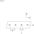
- FIGS. 1 and 2 illustrate a schematic diagram of a grain oriented electrical steel sheet 10 magnetically refined according to an embodiment of the present invention.
- the grain oriented electrical steel sheet 10 includes linear grooves 20 formed on one surface 11 or both surfaces 11 and 12 of the electrical steel sheet in a direction (X 1 direction) crossing a rolling direction (RD direction) and punctuated grooves 30 formed on one surface 11 or both surfaces 11 and 12 of the electrical steel sheet so as to be arranged in a direction (X 2 direction) crossing the rolling direction.
- the plurality of linear grooves 20 and the plurality of punctuated grooves 30 are formed in the rolling direction, and an interval D3 between the punctuated grooves with respect to an arrangement direction (X 2 direction) of the punctuated grooves is 0.02 to 1.7 times an interval D2 between the punctuated grooves with respect to the rolling direction.
- the linear groove 20 and the punctuated groove 30 are formed at the same time, so magnetic properties and electrical insulation properties may be improved at the same time.
- the linear groove 20 or the punctuated groove 30 may be formed alone, heel-up occurs due to an increase in groove depth to secure magnetic properties, resulting in poor magnetic properties and electrical insulation.
- the magnetic properties and electrical insulation properties can be simultaneously improved.
- a ratio D3/D2 of the interval D3 between the punctuated grooves with respect to the arrangement direction (X 2 direction) of the punctuated grooves and the interval D2 between the punctuated grooves with respect to the rolling direction is also important.
- the punctuated groove 30 becomes similar to the linear groove, making it difficult to obtain the effect of simultaneously forming the linear groove 20 or the punctuated groove 30.
- the linear groove 20 becomes the same shape as when the punctuated groove 30 is not substantially formed, so it is difficult to obtain the effect of simultaneously forming the linear groove 20 or the punctuated groove 30.
- the interval D3 between the punctuated grooves with respect to the arrangement direction (X 2 direction) of the punctuated grooves is 0.02 to 1.7 times the interval D2 between the punctuated grooves with respect to the rolling direction. More specifically, it needs to be 0.30 to 1.7 times. More specifically, it needs to be 0.65 to 1.7 times.
- the interval between the linear grooves 20 is indicated as D1
- the interval between the punctuated grooves 30 with respect to the rolling direction is indicated as D2.
- the interval between the punctuated grooves with respect to the arrangement direction (X 2 direction) of the punctuated grooves is indicated as D3.
- an arbitrary linear groove 20 and a linear groove 20 closest to the arbitrary linear groove 20 are defined as the interval D1 between the grooves.
- a punctuated groove 30 closest to an arbitrary punctuated groove 30 in the rolling direction is defined as the interval D2 between punctuated grooves.
- an arbitrary punctuated groove 30 and a punctuated groove 30 closest to the arbitrary punctuated groove 30 in the arrangement direction (X 2 direction) of the punctuated groove are defined as the interval D2 between the punctuated grooves.
- the interval is defined based on a center line of the linear groove 20 and an outermost line of the punctuated groove 30.
- the linear groove 20 and the punctuated groove 30 are substantially parallel, but when they are not parallel, the closest position is regarded as an interval.
- an average value of each interval D1, D2, and D3, that is, a value obtained by dividing a total sum of the intervals D1, D2, and D3 by the total number may satisfy the above-described range.
- the interval D3 between the punctuated grooves with respect to the arrangement direction (X 2 direction) of the punctuated grooves may be 0.01 to 9.00 mm, and the interval D2 between the punctuated grooves with respect to the rolling direction may be 1.8 to 5.0 mm.
- the interval D3 between the punctuated grooves with respect to the arrangement direction (X 2 direction) of the punctuated grooves is too large, the effect of forming only the linear groove 20 instead of the punctuated groove 30 occurs, resulting in poor magnetism and insulation.
- the interval D2 between the punctuated grooves in the rolling direction is too small, the effect of forming only the punctuated grooves 30 instead of the linear grooves 20 may occur, resulting in poor magnetism and insulation.
- the interval D2 between the punctuated grooves with respect to the rolling direction is too large, the effect of forming only the linear grooves 20 instead of the linear grooves 20 may occur, resulting in poor magnetism and insulation. More specifically, the interval D3 between the punctuated grooves with respect to the arrangement direction (X 2 direction) of the punctuated grooves may be 0.1 to 3.0 mm, and the interval D2 between the punctuated grooves with respect to the rolling direction may be 2.0 to 4.0mm.
- the interval D1 between the linear grooves 20 with respect to the rolling direction may be 0.2 to 3.0 times the interval D2 between the punctuated grooves 30 with respect to the rolling direction.
- FIG. 3 illustrates the case where one punctuated groove 30 is formed between the linear grooves 20, that is, the case where D2/D1 is 1, but is not limited thereto.
- the interval D1 between the linear grooves 20 with respect to the rolling direction may be 0.5 to 1.5 times the interval D2 between the punctuated grooves 30 with respect to the rolling direction.
- the interval D1 between the linear grooves 20 with respect to the rolling direction may be 2 to 15 mm.
- the interval D1 between the linear grooves 20 with respect to the rolling direction, the interval D2 between the punctuated grooves 30 with respect to the rolling direction, and the interval D3 between the punctuated grooves with respect to the arrangement direction (X 2 direction) of the punctuated grooves may be constant within the entire electrical sheet. Specifically, all the intervals D1, D2, and D3 within the entire electrical sheet may fall within 10% of average intervals D1, D2, and D3. More specifically, it may correspond to within 1%.
- FIGS. 1 and 2 illustrate that the linear groove 20 and the punctuated groove 30 are formed on one surface 11 of the steel sheet, but are not limited thereto.
- the linear groove 20 is formed on one surface 11 of the steel sheet, and the punctuated groove 30 is formed on the other surface 12 of the steel sheet.
- D2/D1 is smaller than 1. More specifically, the interval D2 between the punctuated grooves 30 may be 0.2 to 0.5 times the interval D1 between the linear grooves 20. In this case, as described above, the average value of each interval D1 and D2 may satisfy the above range. More specifically, the interval D2 between the punctuated grooves 30 may be 0.2 to 0.4 times the interval D1 between the linear grooves 20.
- D2/D1 is greater than 1. More specifically, the interval D2 between the punctuated grooves 30 may be 2 to 2.8 times the interval D1 between the linear grooves 20.
- the linear groove 20 and the punctuated groove 30 refer to a part of the surface of the steel sheet removed by irradiation with a laser, plasma, an ion beam, or the like.
- the shape of the linear groove 20 is expressed as a wedge shape
- the shape of the punctuated groove 30 is expressed as a semicircular shape, but this is only an example, and the linear groove 20 and the punctuated groove 30 may be formed in various shapes such as square, trapezoidal, U-shaped, and W-shape.
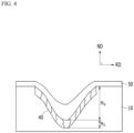
- FIG. 4 illustrates a schematic diagram of the linear groove 20 or the punctuated groove 30 according to the embodiment of the present invention.
- a depth H G of the linear groove 20 or the punctuated groove 30 may be 5 to 15% of the thickness of the steel sheet.
- the depth H G of the groove is too shallow, it is difficult to obtain an appropriate core loss improvement effect.
- the structural characteristics of the steel sheet 10 may greatly change due to strong laser irradiation, or a large amount of heel-up and spatter may be formed to deteriorate magnetism. Accordingly, it is possible to control the depth of the linear groove 20 or the punctuated groove 30 within the above-described range.
- a solidified alloy layer 40 is formed below the linear groove 20 or the punctuated groove 30, and may have a thickness H c of 0.1 ⁇ m to 3 ⁇ m.
- H c thickness of the solidified alloy layer 40
- the solidified alloy layer contains recrystallization with an average grain size of 1 to 10 ⁇ m, and is distinguished from other steel sheet parts.
- an insulating film layer 50 may be formed above the linear groove 20 or the punctuated groove 30 .
- FIGS. 1 and 2 illustrate that the longitudinal direction (X 1 direction) of the linear groove 20 or the arrangement direction (X 2 direction) of the punctuated groove 30 and the rolling direction (RD direction) form a right angle, but are not limited thereto.
- the longitudinal direction (X 1 direction) of the linear groove 20 or the arrangement direction (X 2 direction) of the punctuated groove 30 may form an angle of 75 to 105°.
- it may contribute to improving the core loss of the grain oriented electrical steel sheet. More specifically, it may be 75 to 88° or 97 to 105°.
- FIG. 1 shows that the linear groove 20 is continuously formed along the rolling vertical direction (TD direction), but is not limited thereto.
- 2 to 10 linear grooves 20 may be intermittently formed along the rolling vertical direction (TD direction) of the steel sheet. When formed intermittently like this, it may contribute to improving the core loss of the grain oriented electrical steel sheet.
- the linear groove may have a diameter L G of 0.02 to 0.40mm with respect to the arrangement direction (X 2 direction) of the punctuated groove. Through an appropriate diameter L G , it may contribute to improving the core loss of the grain oriented electrical steel sheet.
- the punctuated groove may have a diameter L G of 0.05 to 0.3mm with respect to the arrangement direction (X 2 direction) of the punctuated groove.
- a method for refining magnetic domains in a grain oriented electrical steel sheet includes preparing the grain oriented electrical steel sheet 10, forming the linear grooves 20 by irradiating a continuous oscillation frequency laser to one surface or both surfaces of the grain oriented electrical steel sheet 10 in a direction crossing a rolling direction (RD direction), and forming the punctuated grooves 30 by irradiating a pulsed oscillation frequency laser to one surface or both surfaces of the grain oriented electrical steel sheet in the direction crossing the rolling direction.
- RD direction rolling direction
- the grain oriented electrical steel sheet 10 is prepared.
- the magnetic domain refinement method and the shapes of the linear groove 20 and the punctuated groove 30 have the above-described features, and the grain oriented electrical steel sheet to be subjected to magnetic domain refinement may be used without limitation.
- the effect of the present invention is exhibited regardless of the alloy composition of the grain oriented electrical steel sheet. Therefore, a detailed description of the alloy composition of the grain oriented electrical steel sheet will be omitted.
- the grain oriented electrical steel sheet may use a grain oriented electrical steel sheet rolled from a slab to a predetermined thickness through hot rolling and cold rolling.
- the grain oriented electrical steel sheets that have undergone primary recrystallization annealing or secondary recrystallization annealing may be used.
- a laser is irradiated to one surface 11 of the grain oriented electrical steel sheet in a direction crossing the rolling direction (RD direction) to form the linear groove 20.
- an energy density Ed of the laser may be 0.5 to 2J/mm 2 .
- the linear groove 20 with an appropriate depth is not formed, and it is difficult to obtain the core loss improvement effect.
- the linear groove 20 with a depth that is too thick is formed, making it difficult to obtain the core loss improvement effect.
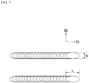
- FIG. 5 illustrates a schematic diagram of the shape of the laser beam.
- the beam length L of the laser in the rolling vertical direction (TD direction) of the steel sheet may be 50 to 750 ⁇ m.
- the laser irradiation time is too short, making it impossible to form an appropriate groove and making it difficult to obtain the core loss improvement effect.
- the beam length L in the rolling vertical direction (TD direction) is too long, the laser irradiation time is too long, so the linear groove 20 having too thick depth is formed, making it difficult to obtain the core loss improvement effect.
- a beam width W of the laser in the rolling direction (RD direction) of the steel sheet may be 10 to 30 ⁇ m.
- the beam width W is too short or too long, the width of the linear groove 20 becomes short or long, so the appropriate magnetic domain refinement effect may not be obtained.
- the shape of the beam is shown as an ellipse in FIG. 5 , it is not limited to a shape such as a sphere or a rectangle.
- a laser having an output of 10 W to 100 kW may be used, and a laser of a Gaussian mode, a single mode, or a fundamental Gaussian mode may be used. It is a TEMoo-shaped beam, and the M2 value may have a value in the range of 1.0 to 1.2.
- the pulsed oscillation frequency laser is irradiated to one surface or both surfaces of the grain oriented electrical steel sheet 10 in the direction crossing the rolling direction (RD direction) to form the punctuated groove 30.
- the forming of the linear groove 20 and the forming of the punctuated groove 30 described above may be performed without any limitations on the time line or later. Specifically, after forming the linear groove 20, the punctuated groove 30 may be formed. In addition, after forming the punctuated groove 30, the linear groove 20 may be formed. In addition, it is also possible to simultaneously form the linear groove 20 and the punctuated groove 30.
- a laser having the same energy density, shape, output, and type as in the forming of the linear groove 20 described above may be used.
- the pulsed oscillation frequency laser may be irradiated.
- the pulsed oscillation frequency laser is a laser in which the output of the laser beam changes over time. Since there is such a change in output, the grooves are not formed in areas where the laser peak energy is low, and the grooves are formed only in areas where the laser peak energy is high, resulting in the formation of the punctuated grooves 30.
- the frequency F q of the laser and the interval D2 between the punctuated grooves with respect to the rolling direction may satisfy Equation 1 below. 11 mm ⁇ s ⁇ F q / D 2 ⁇ 20000 mm ⁇ s (In Equation 1, [F q ] represents the frequency (Hz) of the laser in the forming of the punctuated groove, and [D2] represents the interval (mm) between the punctuated grooves with respect to the rolling direction.)
- the punctuated groove 30 becomes similar to the linear groove, making it difficult to obtain the effect of simultaneously forming the linear groove 20 or the punctuated groove 30.
- the linear groove 20 becomes the same shape as when the punctuated groove 30 is not substantially formed, so it is difficult to obtain the effect of simultaneously forming the linear groove 20 or the punctuated groove 30.
- the value of Equation 1 needs to be 111 to 2000 mm.s.
- the frequency F q of the laser may be 20 to 100 kHz. In the above range, the punctuated groove 30 is appropriately formed, so the magnetism and insulation may be improved at the same time.
- the duty of the laser may be 50% or less.
- the duty represents a ratio T b /T a of [irradiation time with an output of 10% or more of maximum output (Pmax)] (T b ) to [output modulation cycle time] (T a ) in the time waveform for the output of the laser beam.
- Pmax maximum output
- T b maximum output
- T a output modulation cycle time
- the method for refining magnetic domains in a grain oriented electrical steel sheet according to an embodiment of the present invention may further include forming the insulating film layer.
- the forming of the insulating film layer may be included after the preparing of the grain oriented electrical steel sheet, after the forming of the linear groove, or after the forming of the punctuated groove. More specifically, it may be included after the forming of the linear groove and the punctuated groove. After forming the linear groove and the punctuated groove, when forming the insulating film layer, there is an advantage in that the insulation coating only needs to be performed once.
- a method of forming an insulating film layer may be used without particular limitation, and for example, the insulating coating layer may be formed by applying an insulating coating liquid containing phosphate.
- an insulating coating liquid it is preferable to use a coating liquid containing colloidal silica and metal phosphate.
- the metal phosphate may be Al phosphate, Mg phosphate, or a combination thereof, and the content of Al, Mg, or a combination thereof relative to the weight of the insulating coating liquid may be 15 wt% or more.
- a grain oriented electrical steel sheet with a thickness of 0.30 mm was prepared by cold rolling, primary recrystallization annealing, and secondary recrystallization annealing.
- a width W of the laser beam is 20 ⁇ m, and a length L of the laser beam is 600 ⁇ m.
- the energy density of the laser was 1.5 J/mm 2 .
- the interval between the linear grooves was 2.5 mm. Groove depths were shown in Table 1 below.
- the width W of the laser beam is 20 ⁇ m
- the length L of the laser beam is 500 ⁇ m.
- the energy density of the laser was 1.5 J/mm 2 .
- the interval D2 between the punctuated grooves in the rolling direction, the interval D3 between the punctuated grooves in the arrangement direction, and the groove depth were shown in Table 1 below.
- Table 1 shows an embodiment of the present invention.
- the coercive force was measured at 50Hz and 1.7T.
- the core loss was measured as a core loss value (W 17/50 ) when the frequency was 50Hz when a value of magnetic flux density was 1.7 Telsa.
Landscapes
- Engineering & Computer Science (AREA)
- Physics & Mathematics (AREA)
- Chemical & Material Sciences (AREA)
- Optics & Photonics (AREA)
- Mechanical Engineering (AREA)
- Power Engineering (AREA)
- Manufacturing & Machinery (AREA)
- Plasma & Fusion (AREA)
- Electromagnetism (AREA)
- Thermal Sciences (AREA)
- Crystallography & Structural Chemistry (AREA)
- Materials Engineering (AREA)
- Metallurgy (AREA)
- Organic Chemistry (AREA)
- Dispersion Chemistry (AREA)
- Soft Magnetic Materials (AREA)
- Manufacturing Of Steel Electrode Plates (AREA)
Abstract
Description
- The present invention relates to a grain oriented electrical steel sheet and a method for refining magnetic domains therein. More particularly, the present invention relates to a grain oriented electrical steel sheet and a method for refining magnetic domains therein capable of securing electrical insulation as well as core loss characteristics by combining continuous grooves and discontinuous grooves.
- Since a grain oriented electrical steel sheet is used as a core material for a transformer using electromagnetic induction in a dry or wet environment, adhesion and corrosion resistance of the coating material are required in the final product sheet state.
- The grain oriented electrical steel sheet contains a large amount of Si, and is a functional steel sheet in which a texture of secondary recrystallized grains is oriented in the same Goss orientation ({110}<001 >) as a rolling direction through melting, casting, hot rolling sheet annealing, cold rolling, and high temperature annealing processes, and the like. In particular, a magnetic domain refinement technology of the grain oriented electrical steel sheet is a technology that improves core loss characteristics by reducing a 180° magnetic domain width in secondary crystal grains when a magnetic field is applied, and is applied to a wide range of thickness products, from ultra-thin materials having a thickness of less than 0.20 mm to thick materials having a thickness of 0.30 mm. Among the magnetic domain refinement technologies, a technology capable of securing a magnetic domain refinement effect even after stress relief annealing (SRA) to improve core loss is called a permanent magnetic domain refinement technology. This permanent magnetic domain refinement technology is used for a transformer core that requires molding and heat treatment due to its technical characteristics, and is necessary to secure electrical insulation as well as core loss characteristics of the iron core in a dry (wet) environment of room temperature or higher.
- The present invention attempts to provide a grain oriented electrical steel sheet and a method for refining magnetic domains therein. Specifically, the present invention attempts to provide a grain oriented electrical steel sheet and a method for refining magnetic domains therein capable of securing electrical insulation as well as core loss characteristics by combining continuous grooves and discontinuous grooves.
- According to one embodiment of the present invention, a grain oriented electrical steel sheet includes: linear grooves formed on one surface or both surfaces of the electrical steel sheet in the direction (X1 direction) crossing a rolling direction; and punctuated grooves formed on one surface or both surfaces of the electrical steel sheet so as to be arranged in the direction (X2 direction) crossing the rolling direction, wherein the plurality of linear grooves and the plurality of punctuated grooves are formed in the rolling direction, and an interval D3 between the punctuated grooves with respect to an arrangement direction (X2 direction) of the punctuated grooves is 0.02 to 1.7 times an interval D2 between the punctuated grooves with respect to the rolling direction.
- The interval D3 between the punctuated grooves with respect to the arrangement direction (X2 direction) of the punctuated grooves may be 0.01 to 9.00 mm, and the interval D2 between the punctuated grooves with respect to the rolling direction may be 1.8 to 5.0 mm.
- An interval D1 between the linear grooves with respect to the rolling direction may be 0.2 to 3 times the interval D2 between the punctuated grooves with respect to the rolling direction.
- The linear groove and the punctuated groove may be formed on one surface of the steel sheet.
- A depth of the linear groove and the punctuated groove may be 5 to 15% of a thickness of the steel sheet.
- A longitudinal direction of the linear groove and the arrangement direction of the punctuated groove may form an angle of 75 to 105° with respect to the rolling direction.
2 to 10 linear grooves may be intermittently formed along a rolling vertical direction of the steel sheet. - The punctuated groove may have a diameter LG of 0.02 to 0.4 mm with respect to the arrangement direction (X2 direction) of the punctuated groove.
- According to another embodiment of the present invention, a method for refining magnetic domains in a grain oriented electrical steel sheet includes: preparing the grain oriented electrical steel sheet; forming linear grooves by irradiating a continuous oscillation frequency laser to one surface or both surfaces of the grain oriented electrical steel sheet in a direction crossing a rolling direction; and forming punctuated grooves by irradiating a pulsed oscillation frequency laser to one surface or both surfaces of the grain oriented electrical steel sheet in the direction crossing the rolling direction.
- The forming of the linear groove and the forming of the punctuated groove may be performed plural times, and an interval D3 between the punctuated grooves with respect to an arrangement direction (X2 direction) of the punctuated grooves may be 0.02 to 1.7 times an interval D2 between the punctuated grooves with respect to the rolling direction.
- In the forming of the punctuated groove, a frequency Fq of the laser may be 20 kHz to 100 kHz.
- In the forming of the punctuated groove, a duty of the laser may be 50% or less.
- In the forming of the linear groove and the forming of the punctuated groove, an energy density of the laser may be 0.5 to 2 J/mm2.
- In the forming of the linear groove and the forming of the punctuated groove, a beam length of the laser in a rolling vertical direction of the steel sheet may be 50 to 750 µm, and a beam width of the laser in the rolling direction of the steel sheet may be 10 to 30 µm.
- According to one embodiment of the present invention, by forming a combination of continuous grooves and discontinuous grooves, it is possible to improve coercive force and core loss, and at the same time, improve electrical insulation properties.
-
-
FIGS. 1 and2 are schematic diagrams of a rolling surface (ND surface) of a grain oriented electrical steel sheet according to an embodiment of the present invention. -
FIG. 3 is a schematic diagram of a cross section (TD surface) of a grain oriented electrical steel sheet according to an embodiment of the present invention. -
FIG. 4 is a schematic diagram of a groove according to an embodiment of the present invention. -
FIG. 5 is a schematic diagram illustrating a shape of a laser beam according to an embodiment of the present invention. - The terms first, second, third, and the like are used to describe, but are not limited to, various parts, components, areas, layers and/or sections. These terms are used only to distinguish a part, component, region, layer, or section from other parts, components, regions, layers, or sections. Accordingly, a first part, a component, an area, a layer, or a section described below may be referred to as a second part, a component, an area, a layer, or a section without departing from the scope of the present invention.
- Terminologies used herein are to mention only a specific exemplary embodiment, and do not to limit the present invention. Singular forms used herein include plural forms as long as phrases do not clearly indicate an opposite meaning. The meaning "including" used in the present specification concretely indicates specific properties, areas, integer numbers, steps, operations, elements, and/or components, and is not to exclude presence or addition of other specific properties, areas, integer numbers, steps, operations, elements, and/or components thereof.
- When a part is referred to as being "above" or "on" other parts, it may be directly above or on other parts, or other parts may be included in between. In contrast, when a part is referred to as being "directly above" another part, no other part is involved in between.
- All terms including technical terms and scientific terms used herein have the same meaning as the meaning generally understood by those skilled in the art to which the present invention pertains unless defined otherwise. Terms defined in commonly used dictionaries are additionally interpreted as having meanings consistent with related technical literature and currently disclosed content, and are not interpreted in ideal or very formal meanings unless defined.
- Hereinafter, an embodiment will be described in detail so that a person of ordinary skill in the art to which the present invention pertains can easily implement the present invention. As those skilled in the art would realize, the described embodiments may be modified in various different ways, and are not limited thereto.
-
FIGS. 1 and2 illustrate a schematic diagram of a grain orientedelectrical steel sheet 10 magnetically refined according to an embodiment of the present invention. - As illustrated in
FIGS. 1 and2 , the grain orientedelectrical steel sheet 10 according to the embodiment of the present invention includeslinear grooves 20 formed on onesurface 11 or bothsurfaces punctuated grooves 30 formed on onesurface 11 or bothsurfaces - The plurality of
linear grooves 20 and the plurality ofpunctuated grooves 30 are formed in the rolling direction, and an interval D3 between the punctuated grooves with respect to an arrangement direction (X2 direction) of the punctuated grooves is 0.02 to 1.7 times an interval D2 between the punctuated grooves with respect to the rolling direction. - According to one embodiment of the present invention, the
linear groove 20 and thepunctuated groove 30 are formed at the same time, so magnetic properties and electrical insulation properties may be improved at the same time. For example, when thelinear groove 20 or thepunctuated groove 30 may be formed alone, heel-up occurs due to an increase in groove depth to secure magnetic properties, resulting in poor magnetic properties and electrical insulation. In one embodiment of the present invention, by combining the linear groove and the punctuated groove, the magnetic properties and electrical insulation properties can be simultaneously improved. - In one embodiment of the present invention, a ratio D3/D2 of the interval D3 between the punctuated grooves with respect to the arrangement direction (X2 direction) of the punctuated grooves and the interval D2 between the punctuated grooves with respect to the rolling direction is also important.
- When the ratio is too small, the
punctuated groove 30 becomes similar to the linear groove, making it difficult to obtain the effect of simultaneously forming thelinear groove 20 or thepunctuated groove 30. In addition, when this ratio is too large, thelinear groove 20 becomes the same shape as when thepunctuated groove 30 is not substantially formed, so it is difficult to obtain the effect of simultaneously forming thelinear groove 20 or thepunctuated groove 30. Accordingly, the interval D3 between the punctuated grooves with respect to the arrangement direction (X2 direction) of the punctuated grooves is 0.02 to 1.7 times the interval D2 between the punctuated grooves with respect to the rolling direction. More specifically, it needs to be 0.30 to 1.7 times. More specifically, it needs to be 0.65 to 1.7 times. - In
FIG. 3 , the interval between thelinear grooves 20 is indicated as D1, and the interval between thepunctuated grooves 30 with respect to the rolling direction is indicated as D2. InFIG. 2 , the interval between the punctuated grooves with respect to the arrangement direction (X2 direction) of the punctuated grooves is indicated as D3. As illustrated inFIG. 1 , when the plurality oflinear grooves 20 and the plurality ofpunctuated grooves 30 are formed, an arbitrarylinear groove 20 and alinear groove 20 closest to the arbitrarylinear groove 20 are defined as the interval D1 between the grooves. In addition, apunctuated groove 30 closest to an arbitrarypunctuated groove 30 in the rolling direction is defined as the interval D2 between punctuated grooves. In addition, as illustrated inFIG. 3 , an arbitrarypunctuated groove 30 and apunctuated groove 30 closest to the arbitrarypunctuated groove 30 in the arrangement direction (X2 direction) of the punctuated groove are defined as the interval D2 between the punctuated grooves. - In addition, in one embodiment of the present invention, since the
linear groove 20 and thepunctuated groove 30 have a thickness in the rolling direction (RD direction), the interval is defined based on a center line of thelinear groove 20 and an outermost line of thepunctuated groove 30. In addition, in one embodiment of the present invention, thelinear groove 20 and the punctuatedgroove 30 are substantially parallel, but when they are not parallel, the closest position is regarded as an interval. In addition, when the plurality oflinear grooves 20 and the plurality of punctuatedgrooves 30 are formed, an average value of each interval D1, D2, and D3, that is, a value obtained by dividing a total sum of the intervals D1, D2, and D3 by the total number may satisfy the above-described range. - The interval D3 between the punctuated grooves with respect to the arrangement direction (X2 direction) of the punctuated grooves may be 0.01 to 9.00 mm, and the interval D2 between the punctuated grooves with respect to the rolling direction may be 1.8 to 5.0 mm. When the interval D3 between the punctuated grooves with respect to the arrangement direction (X2 direction) of the punctuated grooves is too large, the effect of forming only the
linear groove 20 instead of the punctuatedgroove 30 occurs, resulting in poor magnetism and insulation. When the interval D2 between the punctuated grooves in the rolling direction is too small, the effect of forming only the punctuatedgrooves 30 instead of thelinear grooves 20 may occur, resulting in poor magnetism and insulation. On the other hand, when the interval D2 between the punctuated grooves with respect to the rolling direction is too large, the effect of forming only thelinear grooves 20 instead of thelinear grooves 20 may occur, resulting in poor magnetism and insulation. More specifically, the interval D3 between the punctuated grooves with respect to the arrangement direction (X2 direction) of the punctuated grooves may be 0.1 to 3.0 mm, and the interval D2 between the punctuated grooves with respect to the rolling direction may be 2.0 to 4.0mm. - The interval D1 between the
linear grooves 20 with respect to the rolling direction may be 0.2 to 3.0 times the interval D2 between the punctuatedgrooves 30 with respect to the rolling direction. -
FIG. 3 illustrates the case where one punctuatedgroove 30 is formed between thelinear grooves 20, that is, the case where D2/D1 is 1, but is not limited thereto. - When the interval D1 between the
linear grooves 20 with respect to the rolling direction is too large, the effect of forming only the punctuatedgrooves 30 may occur, resulting in poor magnetism and insulation. On the other hand, when the interval D1 between thelinear grooves 20 with respect to the rolling direction is too small, the effect of forming only thelinear grooves 20 may occur, resulting in poor magnetism and insulation. More specifically, the interval D1 between thelinear grooves 20 with respect to the rolling direction may be 0.5 to 1.5 times the interval D2 between the punctuatedgrooves 30 with respect to the rolling direction. - More specifically, the interval D1 between the
linear grooves 20 with respect to the rolling direction may be 2 to 15 mm. - The interval D1 between the
linear grooves 20 with respect to the rolling direction, the interval D2 between the punctuatedgrooves 30 with respect to the rolling direction, and the interval D3 between the punctuated grooves with respect to the arrangement direction (X2 direction) of the punctuated grooves may be constant within the entire electrical sheet. Specifically, all the intervals D1, D2, and D3 within the entire electrical sheet may fall within 10% of average intervals D1, D2, and D3. More specifically, it may correspond to within 1%. -
FIGS. 1 and2 illustrate that thelinear groove 20 and the punctuatedgroove 30 are formed on onesurface 11 of the steel sheet, but are not limited thereto. For example, it is also possible that thelinear groove 20 is formed on onesurface 11 of the steel sheet, and the punctuatedgroove 30 is formed on theother surface 12 of the steel sheet. - For example, it is also possible that D2/D1 is smaller than 1. More specifically, the interval D2 between the punctuated
grooves 30 may be 0.2 to 0.5 times the interval D1 between thelinear grooves 20. In this case, as described above, the average value of each interval D1 and D2 may satisfy the above range. More specifically, the interval D2 between the punctuatedgrooves 30 may be 0.2 to 0.4 times the interval D1 between thelinear grooves 20. - Conversely, it is also possible that D2/D1 is greater than 1. More specifically, the interval D2 between the punctuated
grooves 30 may be 2 to 2.8 times the interval D1 between thelinear grooves 20. - As illustrated in
FIG. 3 , thelinear groove 20 and the punctuatedgroove 30 refer to a part of the surface of the steel sheet removed by irradiation with a laser, plasma, an ion beam, or the like. InFIG. 1 , the shape of thelinear groove 20 is expressed as a wedge shape, and the shape of the punctuatedgroove 30 is expressed as a semicircular shape, but this is only an example, and thelinear groove 20 and the punctuatedgroove 30 may be formed in various shapes such as square, trapezoidal, U-shaped, and W-shape. -
FIG. 4 illustrates a schematic diagram of thelinear groove 20 or the punctuatedgroove 30 according to the embodiment of the present invention. A depth HG of thelinear groove 20 or the punctuatedgroove 30 may be 5 to 15% of the thickness of the steel sheet. When the depth HG of the groove is too shallow, it is difficult to obtain an appropriate core loss improvement effect. When the depth HG of the groove is too deep, the structural characteristics of thesteel sheet 10 may greatly change due to strong laser irradiation, or a large amount of heel-up and spatter may be formed to deteriorate magnetism. Accordingly, it is possible to control the depth of thelinear groove 20 or the punctuatedgroove 30 within the above-described range. - As illustrated in
FIG. 4 , a solidifiedalloy layer 40 is formed below thelinear groove 20 or the punctuatedgroove 30, and may have a thickness Hc of 0.1 µm to 3 µm. By appropriately controlling the thickness of the solidifiedalloy layer 40, only a spike domain is formed in a groove portion after the final insulation coating without affecting the formation of secondary recrystallization. When the thickness of the solidifiedalloy layer 40 is too thick, since it affects the recrystallization during the first recrystallization, so the Goss density of the second recrystallization after the secondary recrystallization annealing is inferior, so, even if laser irradiation is performed on the secondary recrystallization steel sheet, the core loss Improvement effect characteristics may not be secured. The solidified alloy layer contains recrystallization with an average grain size of 1 to 10 µm, and is distinguished from other steel sheet parts. - As illustrated in
FIG. 4 , an insulatingfilm layer 50 may be formed above thelinear groove 20 or the punctuatedgroove 30 . -
FIGS. 1 and2 illustrate that the longitudinal direction (X1 direction) of thelinear groove 20 or the arrangement direction (X2 direction) of the punctuatedgroove 30 and the rolling direction (RD direction) form a right angle, but are not limited thereto. For example, the longitudinal direction (X1 direction) of thelinear groove 20 or the arrangement direction (X2 direction) of the punctuatedgroove 30 may form an angle of 75 to 105°. When forming the above-described angle, it may contribute to improving the core loss of the grain oriented electrical steel sheet. More specifically, it may be 75 to 88° or 97 to 105°. -
FIG. 1 shows that thelinear groove 20 is continuously formed along the rolling vertical direction (TD direction), but is not limited thereto. For example, 2 to 10linear grooves 20 may be intermittently formed along the rolling vertical direction (TD direction) of the steel sheet. When formed intermittently like this, it may contribute to improving the core loss of the grain oriented electrical steel sheet. - The linear groove may have a diameter LG of 0.02 to 0.40mm with respect to the arrangement direction (X2 direction) of the punctuated groove. Through an appropriate diameter LG, it may contribute to improving the core loss of the grain oriented electrical steel sheet. The punctuated groove may have a diameter LG of 0.05 to 0.3mm with respect to the arrangement direction (X2 direction) of the punctuated groove.
- A method for refining magnetic domains in a grain oriented electrical steel sheet according to an embodiment of the present invention includes preparing the grain oriented
electrical steel sheet 10, forming thelinear grooves 20 by irradiating a continuous oscillation frequency laser to one surface or both surfaces of the grain orientedelectrical steel sheet 10 in a direction crossing a rolling direction (RD direction), and forming the punctuatedgrooves 30 by irradiating a pulsed oscillation frequency laser to one surface or both surfaces of the grain oriented electrical steel sheet in the direction crossing the rolling direction. - First, the grain oriented
electrical steel sheet 10 is prepared. In one embodiment of the present invention, the magnetic domain refinement method and the shapes of thelinear groove 20 and the punctuatedgroove 30 have the above-described features, and the grain oriented electrical steel sheet to be subjected to magnetic domain refinement may be used without limitation. In particular, the effect of the present invention is exhibited regardless of the alloy composition of the grain oriented electrical steel sheet. Therefore, a detailed description of the alloy composition of the grain oriented electrical steel sheet will be omitted. - In one embodiment of the present invention, the grain oriented electrical steel sheet may use a grain oriented electrical steel sheet rolled from a slab to a predetermined thickness through hot rolling and cold rolling. In addition, the grain oriented electrical steel sheets that have undergone primary recrystallization annealing or secondary recrystallization annealing may be used.
- Next, a laser is irradiated to one
surface 11 of the grain oriented electrical steel sheet in a direction crossing the rolling direction (RD direction) to form thelinear groove 20. - In this case, an energy density Ed of the laser may be 0.5 to 2J/mm2. When the energy density is too small, the
linear groove 20 with an appropriate depth is not formed, and it is difficult to obtain the core loss improvement effect. Conversely, even if the energy density is too large, thelinear groove 20 with a depth that is too thick is formed, making it difficult to obtain the core loss improvement effect. -
FIG. 5 illustrates a schematic diagram of the shape of the laser beam. In the forming of thelinear groove 20, the beam length L of the laser in the rolling vertical direction (TD direction) of the steel sheet may be 50 to 750 µm. When the beam length L in the rolling vertical direction (TD direction) is too short, the laser irradiation time is too short, making it impossible to form an appropriate groove and making it difficult to obtain the core loss improvement effect. Conversely, when the beam length L in the rolling vertical direction (TD direction) is too long, the laser irradiation time is too long, so thelinear groove 20 having too thick depth is formed, making it difficult to obtain the core loss improvement effect. - A beam width W of the laser in the rolling direction (RD direction) of the steel sheet may be 10 to 30 µm. When the beam width W is too short or too long, the width of the
linear groove 20 becomes short or long, so the appropriate magnetic domain refinement effect may not be obtained. - Although the shape of the beam is shown as an ellipse in
FIG. 5 , it is not limited to a shape such as a sphere or a rectangle. - As the laser, a laser having an output of 10 W to 100 kW may be used, and a laser of a Gaussian mode, a single mode, or a fundamental Gaussian mode may be used. It is a TEMoo-shaped beam, and the M2 value may have a value in the range of 1.0 to 1.2.
- Next, the pulsed oscillation frequency laser is irradiated to one surface or both surfaces of the grain oriented
electrical steel sheet 10 in the direction crossing the rolling direction (RD direction) to form the punctuatedgroove 30. - The forming of the
linear groove 20 and the forming of the punctuatedgroove 30 described above may be performed without any limitations on the time line or later. Specifically, after forming thelinear groove 20, the punctuatedgroove 30 may be formed. In addition, after forming the punctuatedgroove 30, thelinear groove 20 may be formed. In addition, it is also possible to simultaneously form thelinear groove 20 and the punctuatedgroove 30. - In the forming of the punctuated
groove 30, a laser having the same energy density, shape, output, and type as in the forming of thelinear groove 20 described above may be used. - However, unlike the forming of the
linear groove 20, in the forming of the punctuatedgroove 30, the pulsed oscillation frequency laser may be irradiated. Unlike a continuous oscillation frequency laser, the pulsed oscillation frequency laser is a laser in which the output of the laser beam changes over time. Since there is such a change in output, the grooves are not formed in areas where the laser peak energy is low, and the grooves are formed only in areas where the laser peak energy is high, resulting in the formation of the punctuatedgrooves 30. - In the forming of the punctuated
groove 30, the frequency Fq of the laser and the interval D2 between the punctuated grooves with respect to the rolling direction may satisfy Equation 1 below.
- When the ratio is too small, the punctuated
groove 30 becomes similar to the linear groove, making it difficult to obtain the effect of simultaneously forming thelinear groove 20 or the punctuatedgroove 30. In addition, when this ratio is too large, thelinear groove 20 becomes the same shape as when the punctuatedgroove 30 is not substantially formed, so it is difficult to obtain the effect of simultaneously forming thelinear groove 20 or the punctuatedgroove 30. More specifically, the value of Equation 1 needs to be 111 to 2000 mm.s. - The frequency Fq of the laser may be 20 to 100 kHz. In the above range, the punctuated
groove 30 is appropriately formed, so the magnetism and insulation may be improved at the same time. - The duty of the laser may be 50% or less. The duty represents a ratio Tb/Ta of [irradiation time with an output of 10% or more of maximum output (Pmax)] (Tb) to [output modulation cycle time] (Ta) in the time waveform for the output of the laser beam. When the duty is properly adjusted, the punctuated
groove 30 is properly formed, so the magnetism and insulation may be improved at the same time. More specifically, it may be 2 to 30%. - The method for refining magnetic domains in a grain oriented electrical steel sheet according to an embodiment of the present invention may further include forming the insulating film layer. The forming of the insulating film layer may be included after the preparing of the grain oriented electrical steel sheet, after the forming of the linear groove, or after the forming of the punctuated groove. More specifically, it may be included after the forming of the linear groove and the punctuated groove. After forming the linear groove and the punctuated groove, when forming the insulating film layer, there is an advantage in that the insulation coating only needs to be performed once.
- A method of forming an insulating film layer may be used without particular limitation, and for example, the insulating coating layer may be formed by applying an insulating coating liquid containing phosphate. As such an insulating coating liquid, it is preferable to use a coating liquid containing colloidal silica and metal phosphate. In this case, the metal phosphate may be Al phosphate, Mg phosphate, or a combination thereof, and the content of Al, Mg, or a combination thereof relative to the weight of the insulating coating liquid may be 15 wt% or more.
- Hereinafter, the present invention will be described in more detail through examples. However, these examples are only for illustrating the present invention, and the present invention is not limited thereto.
- A grain oriented electrical steel sheet with a thickness of 0.30 mm was prepared by cold rolling, primary recrystallization annealing, and secondary recrystallization annealing. A continuous wave laser of a Gaussian mode with 1.0 kW, M2 = 1.07 was irradiated to the electrical steel sheet to form a linear groove having an angle of 86° with the RD direction. A width W of the laser beam is 20 µm, and a length L of the laser beam is 600 µm. The energy density of the laser was 1.5 J/mm2. The interval between the linear grooves was 2.5 mm. Groove depths were shown in Table 1 below.
- The electrical sheet was irradiated with a pulsed laser with an average power of 500 W and M2 = 1.2 to form the punctuated groove at an angle of 86° with the RD direction. The width W of the laser beam is 20 µm, and the length L of the laser beam is 500 µm. The energy density of the laser was 1.5 J/mm2. The interval D2 between the punctuated grooves in the rolling direction, the interval D3 between the punctuated grooves in the arrangement direction, and the groove depth were shown in Table 1 below.
- After forming the grooves, pickling and brushing were performed, and insulation coating was applied.
- Table 1 shows an embodiment of the present invention.
- Thereafter, heat treatment was performed at 840°C, and coercive force, core loss, and insulation were measured and summarized in Table 1 below.
- The coercive force was measured at 50Hz and 1.7T.
- The core loss was measured as a core loss value (W17/50) when the frequency was 50Hz when a value of magnetic flux density was 1.7 Telsa.
- The insulation was measured by the Franklin Insulation Teset method of ASTM A717
(Table 1) Lin ear gro ove dep th (%) Punct uated groov e depth (%) Punct uated groov e interva l in rolling directi on (D2, mm) Punctu ated groove interval in arrang ement directio n (D3, mm) Laser freque ncy when form in g punctu ated groov e (kHz) Laser duty when form in g punctu ated groov e (%) D3 / D 2Coer cive force (A/m ) core loss( W/kg) Insulat ion (mA) Exampl e 1 6.5 5.0 1.8 0.036 0.5 5 0.0 2 17.9 0.82 8 Exampl e 27.0 7.0 2.5 0.750 1.0 10 0.3 0 17.8 0.79 6 Exampl e 3 9.0 9.0 3.5 2.275 2.0 3 0.6 5 17.9 0.80 15 Example 4 9.0 13.0 5.0 8.500 2.5 5 1.7 17.7 0.81 20 Compa rative Exampl e 1 3.0 4.2 2.5 0.025 0.5 10 0.0 1 19.7 0.90 95 Compa rative Exampl e2 3.0 4.0 5.0 9.000 2.5 5 1.8 0 19.6 0.91 88 - As shown in Table 1, in Examples 1 to 4, the interval D2 between the punctuated grooves in the rolling direction and the interval D3 between the punctuated grooves in the arrangement direction (X2 direction) are properly adjusted, so it can be confirmed that the coercive force, the core loss, and the insulation are excellent at the same time.
- On the other hand, in Comparative Example 1, the interval D3 between the punctuated grooves in the arrangement direction (X2 direction) was too narrow, and thus, is substantially similar to the case where only the linear grooves were formed, so it can be confirmed that the coercive force, the core loss, and the insulation were inferior.
- In Comparative Example 2, the interval D3 between the punctuated grooves in the arrangement direction (X2 direction) is too wide, and it can be seen that the coercive force, the iron loss, and the insulation are inferior.
- The present invention is not limited to the embodiments, but may be manufactured in a variety of different forms, and those of ordinary skill in the art to which the present invention pertains will understand that the present invention may be implemented in other specific forms without changing the technical spirit or essential features of the present invention. Therefore, it should be understood that the above-mentioned exemplary embodiments are exemplary in all aspects but are not limited thereto.
<Description of symbols> 10: Grain oriented electrical steel sheet 11: One surface of steel sheet 12: Other surface of steel sheet 20: Linear groove 30: Punctuated groove 40: Solidified alloy layer 50: Insulating film layer
Claims (13)
- A grain oriented electrical steel sheet, comprising:linear grooves formed on one surface or both surfaces of the electrical steel sheet in a direction (X1 direction) crossing a rolling direction; andpunctuated grooves formed on one surface or both surfaces of the electrical steel sheet so as to be arranged in a direction (X2 direction) crossing the rolling direction,wherein the plurality of linear grooves and the plurality of punctuated grooves are formed in the rolling direction, andan interval D3 between the punctuated grooves with respect to an arrangement direction (X2 direction) of the punctuated grooves is 0.02 to 1.7 times an interval D2 between the punctuated grooves with respect to the rolling direction.
- The grain oriented electrical steel sheet of claim 1, wherein:
the interval D3 between the punctuated grooves with respect to the arrangement direction (X2 direction) of the punctuated grooves is 0.01 to 9.0 mm, and the interval D2 between the punctuated grooves with respect to the rolling direction is 1.8 to 5.0 mm. - The grain oriented electrical steel sheet of claim 1, wherein:
an interval D1 between the linear grooves with respect to the rolling direction is 0.2 to 3 times the interval D2 between the punctuated grooves with respect to the rolling direction. - The grain oriented electrical steel sheet of claim 1, wherein:
the linear groove and the punctuated groove are formed on one surface of the steel sheet. - The grain oriented electrical steel sheet of claim 1, wherein:
A depth of the linear groove and the punctuated groove is 5 to 15% of a thickness of the steel sheet. - The grain oriented electrical steel sheet of claim 1, wherein:
a longitudinal direction of the linear groove and the arrangement direction of the punctuated groove form an angle of 75 to 105° with respect to the rolling direction. - The grain oriented electrical steel sheet of claim 1, wherein:
2 to 10 linear grooves are intermittently formed along a rolling vertical direction of the steel sheet. - The grain oriented electrical steel sheet of claim 1, wherein:
the punctuated groove has a diameter of 0.02 to 0.4 mm with respect to the arrangement direction (X2 direction) of the punctuated groove. - A method for refining magnetic domains in a grain oriented electrical steel sheet, comprising:preparing the grain oriented electrical steel sheet;forming linear grooves by irradiating a continuous oscillation frequency laser to one surface or both surfaces of the grain oriented electrical steel sheet in a direction crossing a rolling direction; andforming punctuated grooves by irradiating a pulsed oscillation frequency laser to one surface or both surfaces of the grain oriented electrical steel sheet in the direction crossing the rolling direction,wherein the forming of the linear groove and the forming of the punctuated groove are performed plural times to form the plurality of linear grooves and punctuated grooves along the rolling direction, andan interval D3 between the punctuated grooves with respect to an arrangement direction (X2 direction) of the punctuated grooves is 0.02 to 1.7 times an interval D2 between the punctuated grooves with respect to the rolling direction.
- The method of claim 9, wherein:
in the forming of the punctuated groove, a frequency Fq of the laser is 20 kHz to 100 kHz. - The method of claim 9, wherein:
in the forming of the punctuated groove, a duty of the laser is 50% or less. - The method of claim 9, wherein:
in the forming of the linear groove and the forming of the punctuated groove, an energy density of the laser is 0.5 to 2 J/mm2. - The method of claim 9, wherein:
in the forming of the linear groove and the forming of the punctuated groove, a beam length of the laser in a rolling vertical direction of the steel sheet is 50 to 750 µm, and a beam width of the laser in the rolling direction of the steel sheet is 10 to 30 µm.
Applications Claiming Priority (2)
| Application Number | Priority Date | Filing Date | Title |
|---|---|---|---|
| KR1020200179813A KR102415741B1 (en) | 2020-12-21 | 2020-12-21 | Grain oriented electrical steel sheet and method for refining magnetic domains therein |
| PCT/KR2021/019216 WO2022139334A1 (en) | 2020-12-21 | 2021-12-16 | Grain-oriented electrical steel sheet, and magnetic domain refining method therefor |
Publications (2)
| Publication Number | Publication Date |
|---|---|
| EP4266331A1 true EP4266331A1 (en) | 2023-10-25 |
| EP4266331A4 EP4266331A4 (en) | 2024-06-12 |
Family
ID=82159670
Family Applications (1)
| Application Number | Title | Priority Date | Filing Date |
|---|---|---|---|
| EP21911401.4A Pending EP4266331A4 (en) | 2020-12-21 | 2021-12-16 | GRAIN-ORIENTED ELECTRICAL STEEL SHEET AND MAGNETIC DOMAIN REFINING PROCESS THEREFOR |
Country Status (6)
| Country | Link |
|---|---|
| US (1) | US20240024985A1 (en) |
| EP (1) | EP4266331A4 (en) |
| JP (1) | JP7680542B2 (en) |
| KR (1) | KR102415741B1 (en) |
| CN (1) | CN116710578A (en) |
| WO (1) | WO2022139334A1 (en) |
Family Cites Families (8)
| Publication number | Priority date | Publication date | Assignee | Title |
|---|---|---|---|---|
| US4963199A (en) * | 1988-10-14 | 1990-10-16 | Abb Power T&D Company, Inc. | Drilling of steel sheet |
| JPH07320922A (en) * | 1994-03-31 | 1995-12-08 | Kawasaki Steel Corp | Unidirectional electrical steel sheet with low iron loss |
| JP4239233B2 (en) * | 1998-03-26 | 2009-03-18 | Jfeスチール株式会社 | Manufacturing method of grain-oriented electrical steel sheet and etching mask forming apparatus for grain-oriented electrical steel sheet |
| JP5000182B2 (en) * | 2006-04-07 | 2012-08-15 | 新日本製鐵株式会社 | Method for producing grain-oriented electrical steel sheet with excellent magnetic properties |
| KR101659350B1 (en) * | 2016-02-11 | 2016-09-23 | 주식회사 포스코 | Grain-oriented electrical steel sheet and method for manufacturing the same |
| KR101944899B1 (en) | 2016-12-22 | 2019-02-01 | 주식회사 포스코 | Method for refining magnetic domains of grain oriented electrical steel sheet |
| KR102044320B1 (en) * | 2017-12-26 | 2019-11-13 | 주식회사 포스코 | Grain oriented electrical steel sheet and method for refining magnetic domains therein |
| JP7010311B2 (en) * | 2018-02-08 | 2022-02-10 | 日本製鉄株式会社 | Directional electrical steel sheet |
-
2020
- 2020-12-21 KR KR1020200179813A patent/KR102415741B1/en active Active
-
2021
- 2021-12-16 EP EP21911401.4A patent/EP4266331A4/en active Pending
- 2021-12-16 US US18/268,407 patent/US20240024985A1/en active Pending
- 2021-12-16 JP JP2023537528A patent/JP7680542B2/en active Active
- 2021-12-16 WO PCT/KR2021/019216 patent/WO2022139334A1/en not_active Ceased
- 2021-12-16 CN CN202180085715.XA patent/CN116710578A/en active Pending
Also Published As
| Publication number | Publication date |
|---|---|
| JP7680542B2 (en) | 2025-05-20 |
| JP2024500836A (en) | 2024-01-10 |
| WO2022139334A1 (en) | 2022-06-30 |
| EP4266331A4 (en) | 2024-06-12 |
| KR102415741B1 (en) | 2022-06-30 |
| CN116710578A (en) | 2023-09-05 |
| US20240024985A1 (en) | 2024-01-25 |
| KR20220089310A (en) | 2022-06-28 |
Similar Documents
| Publication | Publication Date | Title |
|---|---|---|
| JP7245285B2 (en) | Grain-oriented electrical steel sheet and its magnetic domain refinement method | |
| US11638971B2 (en) | Grain-oriented silicon steel with low core loss and manufacturing method therefore | |
| US6083326A (en) | Grain-oriented electromagnetic steel sheet | |
| EP3239325B1 (en) | Directional electrical steel sheet and method for producing same | |
| KR101944899B1 (en) | Method for refining magnetic domains of grain oriented electrical steel sheet | |
| EP3733881B1 (en) | Grain-oriented electrical steel sheet and magnetic domain refining method therefor | |
| JP7440638B2 (en) | Grain-oriented electrical steel sheet and its magnetic domain refinement method | |
| EP4266331A1 (en) | Grain-oriented electrical steel sheet, and magnetic domain refining method therefor | |
| WO2016105055A1 (en) | Directional electrical steel sheet and method for producing same | |
| JP7391087B2 (en) | Grain-oriented electrical steel sheet and its magnetic domain refinement method |
Legal Events
| Date | Code | Title | Description |
|---|---|---|---|
| STAA | Information on the status of an ep patent application or granted ep patent |
Free format text: STATUS: THE INTERNATIONAL PUBLICATION HAS BEEN MADE |
|
| PUAI | Public reference made under article 153(3) epc to a published international application that has entered the european phase |
Free format text: ORIGINAL CODE: 0009012 |
|
| STAA | Information on the status of an ep patent application or granted ep patent |
Free format text: STATUS: REQUEST FOR EXAMINATION WAS MADE |
|
| 17P | Request for examination filed |
Effective date: 20230705 |
|
| AK | Designated contracting states |
Kind code of ref document: A1 Designated state(s): AL AT BE BG CH CY CZ DE DK EE ES FI FR GB GR HR HU IE IS IT LI LT LU LV MC MK MT NL NO PL PT RO RS SE SI SK SM TR |
|
| DAV | Request for validation of the european patent (deleted) | ||
| DAX | Request for extension of the european patent (deleted) | ||
| A4 | Supplementary search report drawn up and despatched |
Effective date: 20240515 |
|
| RIC1 | Information provided on ipc code assigned before grant |
Ipc: B23K 103/04 20060101ALN20240508BHEP Ipc: B23K 101/18 20060101ALN20240508BHEP Ipc: B23K 26/40 20140101ALI20240508BHEP Ipc: B23K 26/364 20140101ALI20240508BHEP Ipc: H01F 41/02 20060101ALI20240508BHEP Ipc: C21D 8/12 20060101ALI20240508BHEP Ipc: H01F 1/16 20060101AFI20240508BHEP |