EP4265863A1 - Fixing implement and pre-stressed concrete - Google Patents
Fixing implement and pre-stressed concrete Download PDFInfo
- Publication number
- EP4265863A1 EP4265863A1 EP21906536.4A EP21906536A EP4265863A1 EP 4265863 A1 EP4265863 A1 EP 4265863A1 EP 21906536 A EP21906536 A EP 21906536A EP 4265863 A1 EP4265863 A1 EP 4265863A1
- Authority
- EP
- European Patent Office
- Prior art keywords
- barrel member
- anchoring device
- fiber reinforced
- reinforced resin
- peripheral surface
- Prior art date
- Legal status (The legal status is an assumption and is not a legal conclusion. Google has not performed a legal analysis and makes no representation as to the accuracy of the status listed.)
- Pending
Links
- 239000011513 prestressed concrete Substances 0.000 title claims description 31
- 239000000835 fiber Substances 0.000 claims abstract description 111
- 238000004873 anchoring Methods 0.000 claims abstract description 100
- 229920005989 resin Polymers 0.000 claims abstract description 80
- 239000011347 resin Substances 0.000 claims abstract description 80
- 230000002093 peripheral effect Effects 0.000 claims abstract description 47
- 230000002787 reinforcement Effects 0.000 claims abstract description 26
- 239000004570 mortar (masonry) Substances 0.000 claims abstract description 5
- 239000004567 concrete Substances 0.000 claims description 58
- 239000000463 material Substances 0.000 claims description 19
- 230000000149 penetrating effect Effects 0.000 claims description 2
- 230000009471 action Effects 0.000 abstract description 29
- 238000005260 corrosion Methods 0.000 abstract description 6
- 230000007797 corrosion Effects 0.000 abstract description 6
- 229920000049 Carbon (fiber) Polymers 0.000 description 17
- 239000004917 carbon fiber Substances 0.000 description 17
- 239000003365 glass fiber Substances 0.000 description 11
- 239000011159 matrix material Substances 0.000 description 11
- 229910000831 Steel Inorganic materials 0.000 description 8
- 239000010959 steel Substances 0.000 description 8
- 229920002748 Basalt fiber Polymers 0.000 description 7
- ZOXJGFHDIHLPTG-UHFFFAOYSA-N Boron Chemical compound [B] ZOXJGFHDIHLPTG-UHFFFAOYSA-N 0.000 description 7
- 239000004760 aramid Substances 0.000 description 7
- 229920006231 aramid fiber Polymers 0.000 description 7
- 230000004323 axial length Effects 0.000 description 7
- 229910052796 boron Inorganic materials 0.000 description 7
- 239000003822 epoxy resin Substances 0.000 description 6
- VNWKTOKETHGBQD-UHFFFAOYSA-N methane Chemical compound C VNWKTOKETHGBQD-UHFFFAOYSA-N 0.000 description 6
- 229920000647 polyepoxide Polymers 0.000 description 6
- 230000000694 effects Effects 0.000 description 5
- JEIPFZHSYJVQDO-UHFFFAOYSA-N iron(III) oxide Inorganic materials O=[Fe]O[Fe]=O JEIPFZHSYJVQDO-UHFFFAOYSA-N 0.000 description 5
- 229920001225 polyester resin Polymers 0.000 description 5
- 239000004645 polyester resin Substances 0.000 description 5
- 230000003014 reinforcing effect Effects 0.000 description 5
- 230000009467 reduction Effects 0.000 description 4
- 230000004888 barrier function Effects 0.000 description 3
- 238000000465 moulding Methods 0.000 description 3
- 238000004804 winding Methods 0.000 description 3
- 239000011440 grout Substances 0.000 description 2
- 238000004519 manufacturing process Methods 0.000 description 2
- 230000003647 oxidation Effects 0.000 description 2
- 238000007254 oxidation reaction Methods 0.000 description 2
- RTAQQCXQSZGOHL-UHFFFAOYSA-N Titanium Chemical compound [Ti] RTAQQCXQSZGOHL-UHFFFAOYSA-N 0.000 description 1
- 239000010426 asphalt Substances 0.000 description 1
- 239000011083 cement mortar Substances 0.000 description 1
- 230000008859 change Effects 0.000 description 1
- 230000003247 decreasing effect Effects 0.000 description 1
- 230000003467 diminishing effect Effects 0.000 description 1
- 230000007613 environmental effect Effects 0.000 description 1
- 238000012423 maintenance Methods 0.000 description 1
- 239000002184 metal Substances 0.000 description 1
- 229910052751 metal Inorganic materials 0.000 description 1
- 230000001629 suppression Effects 0.000 description 1
- 239000010936 titanium Substances 0.000 description 1
- 229910052719 titanium Inorganic materials 0.000 description 1
Images


Classifications
-
- E—FIXED CONSTRUCTIONS
- E04—BUILDING
- E04C—STRUCTURAL ELEMENTS; BUILDING MATERIALS
- E04C5/00—Reinforcing elements, e.g. for concrete; Auxiliary elements therefor
- E04C5/08—Members specially adapted to be used in prestressed constructions
- E04C5/12—Anchoring devices
- E04C5/122—Anchoring devices the tensile members are anchored by wedge-action
Definitions
- the present invention relates to an anchoring device and a prestressed concrete (PC), and more specifically relates to an anchoring device used to tension a wire in a prestressed concrete and the prestressed concrete.
- PC prestressed concrete
- a wedge-type anchoring device including a barrel member (sleeve member) which is fixed to a PC concrete block and has a through hole having a tapered shape, and multiple wedge members which each have an outer peripheral surface having a tapered shape and slidably contacting an inner peripheral surface of the through hole and which cooperate with each other to grip the wire (for example, Patent Document 1).
- the barrel member is fixed to the concrete block, and the end of the wire is gripped or anchored by the multiple wedge members according to wedge action of the wedge members being pushed into the tapered side of the through hole.
- Patent Document 1 JPH11-210163 A
- General wedge-type anchoring devices which are conventionally known may have a barrel member made of steel or a barrel member made of resin. Those with a barrel member made of steel have sufficient strength against diameter expansion deformation of the barrel member due to wedge action, but corrosion (rust) may occur depending on environmental conditions. Those with a barrel member made of resin do not cause corrosion but are difficult to have sufficient strength against the diameter expansion deformation of the barrel member due to wedge action.
- a task to be accomplished by the present invention is to provide a wedge-type anchoring device in which the barrel member does not corrode, and which has sufficient strength against the diameter expansion deformation of the barrel member due to wedge action.
- An anchoring device is an anchoring device (10) for an end of a wire (110), comprising: a barrel member (12) which is composed of resin or mortar and has a through hole (14) having a tapered shape; multiple wedge members (20) which each have an outer peripheral surface (20A) having a tapered shape and slidably contacting an inner peripheral surface (14A) of the through hole and which cooperate with each other to grip the wire; and a reinforcement member (16, 52, 60, 70) including a part that extends in a circumferential direction of the barrel member to suppress diameter expansion deformation of the barrel member.
- the barrel member does not corrode, and sufficient strength against the diameter expansion deformation of the barrel member due to wedge action is provided.
- each wedge member is composed of resin or fiber reinforced resin.
- the wedge members do not corrode.
- the reinforcement member comprises fibers (16, 52) embedded in the barrel member.
- the barrel member and the reinforcement member can be integrally molded, which allows excellent productivity of the anchoring device.
- the barrel member is composed of a prepreg (42, 44, 46, 48) wound cylindrically so as to have an outer peripheral surface (42A, 44A, 46A, 48A) tapered in steps in a direction same as that of the tapered shape of the through hole, the prepreg comprises a base material (50) made of resin and fibers (52) impregnated in the base material, and the reinforcement member is composed of fibers comprised in the prepreg.
- the barrel member including the reinforcement member is manufactured efficiently by using the prepreg, whereby the productivity is excellent. Further, the wall thickness of the barrel member can be made close to a uniform thickness over the entire length in the axial direction, and the barrel member can be made compact and lightweight.
- the prepreg is composed of multiple strip-shaped bodies disposed to overlap with each other in a radial direction at parts in an axial direction of the through hole.
- the required shape of the barrel member is reliably formed by the prepreg.
- the reinforcement member comprises an annular body (30) provided on an outer circumference of the barrel member to surround the barrel member.
- the diameter expansion of the barrel member is effectively suppressed by the annular body, whereby the diameter expansion deformation of the barrel member due to wedge action is effectively suppressed.
- the barrel member is composed of fiber reinforced resin
- the annular body is composed of fiber reinforced resin having a higher Young's modulus than the fiber reinforced resin composing the barrel member.
- the annular body is provided partially in an axial direction of the through hole.
- the material cost is reduced compared to a case where the annular body is provided over the entirety in the axial direction of the through hole.
- the annular body is provided continuously over an entirety in an axial direction of the through hole.
- the barrel member has an outer peripheral surface (12C) having a cylindrical shape
- the reinforcement member comprises a spiral restraint body (60) wound on the outer peripheral surface of the barrel member.
- the diameter expansion of the barrel member is effectively suppressed by the spiral restraint body, whereby the diameter expansion deformation of the barrel member due to wedge action is effectively suppressed.
- the barrel member is composed of fiber reinforced resin
- the spiral restraint body is composed of fiber reinforced resin having a higher Young's modulus than the fiber reinforced resin composing the barrel member.
- the diameter expansion deformation of the barrel member is reliably suppressed, and in addition, the material cost is reduced compared to a case where the barrel member also is composed of fiber reinforced resin having a high Young's modulus.
- the barrel member has a spiral groove (12D) on the outer peripheral surface, and the spiral restraint body is fitted in the spiral groove.
- the barrel member has an outer peripheral surface (12E) having a conical shape
- the reinforcement member comprises an annular restraint body (70) fitted on the outer peripheral surface of the barrel member.
- the annular restraint body acts to suppress the diameter expansion of the barrel member, whereby the diameter expansion deformation of the barrel member due to wedge action is suppressed.
- the barrel member is composed of fiber reinforced resin
- the annular restraint body is composed of fiber reinforced resin having a higher Young's modulus than the fiber reinforced resin composing the barrel member.
- the diameter expansion deformation of the barrel member is reliably suppressed, and in addition, the material cost is reduced compared to a case where the barrel member also is composed of fiber reinforced resin having a high Young's modulus.
- an end surface (70B) of the annular restraint body on a tapered side of the conical shape of the barrel member includes a surface perpendicular to an axial direction of the barrel member.
- a prestressed concrete according to one embodiment of the present invention comprises: a concrete block having a rectangular parallelepiped shape; a wire penetrating in a longitudinal direction of the concrete block; and the anchoring device according to the above-described embodiment which is provided at each of two end portions of the concrete block in the longitudinal direction and to which an end portion of the wire is locked.
- the anchoring device may either be embedded in the concrete block or be mounted to the concrete block such that one end surface (12B) of the barrel member contacts an end surface of the concrete block and an outer peripheral surface (12C, 12E) of the barrel member is exposed to outside.
- a prestressed concrete 100 includes a concrete block 102 molded in a rectangular parallelepiped shape, a cylindrical sheath 104 made of resin and embedded in the concrete block 102 to extend in the longitudinal direction of the concrete block 102, and a cable (wire) 106 composed of fiber reinforced resin or metal and disposed in the sheath 104 to penetrate the concrete block 102 in the longitudinal direction.
- a space between the sheath 104 and the cable 106 is filled with grout 108 consisting of cement mortar or the like.
- the prestressed concrete 100 further includes left and right anchoring devices 10 which are provided at both longitudinal end portions of the concrete block 102 (left and right end portions as seen in Figure 1 ) and to which the end portions of the cable 106 are locked.
- the left and right anchoring devices 10 sandwich the concrete block 102 from both sides in the longitudinal direction and fix (anchor) the cable 106 in the concrete block 102 to be in a state of tension. Thereby, prestress is given to the concrete block 102.
- the left and right anchoring devices 10 are of a wedge type and each include a cylindrical barrel member 12 and a pair of upper and lower wedge members 20 as seen in Figure 1 . Since the left and right anchoring devices 10 have the same structure, in the following, description will be made taking the anchoring device 10 disposed on the left side as an example.
- the barrel member 12 includes an outer end 12A exposed to outside from the concrete block 102, an inner end 12B joined to an end surface 110A of an anchoring device embedding hole 110 of the concrete block 102, and an outer peripheral surface 12C joined to an inner peripheral surface 110B of the anchoring device embedding hole 110, and the entirety of the barrel member 12 is embedded in an end portion of the concrete block 102.
- the barrel member 12 is fixed to the concrete block 102 so as not to be displaceable both in the axial direction (the left-right direction as seen in Figure 2 ), which is a direction of prestress application to the concrete block 102 and in the radial direction.
- the embedding of the barrel member 12 in the concrete block 102 may be performed when the concrete block 102 is molded.
- the anchoring device embedding hole 110 is formed when the concrete block 102 is molded.
- the barrel member 12 has a through hole 14 extending through a central part thereof in the axial direction.
- the through hole 14 is a hole having a tapered shape extending from the outer end 12A to the inner end 12B of the barrel member 12, with both ends open.
- the through hole 14 is a tapered hole having an inner diameter gradually decreasing from the outer end 12A to the inner end 12B of the barrel member 12.
- the barrel member 12 is a molded product made of resin such as epoxy resin, polyester resin, or the like. As shown in Figure 2(A) , the barrel member 12 has mesh-like or sheet-like fibers 16 embedded therein.
- the fibers 16 may be glass fibers, carbon fibers, boron fibers, aramid fibers, basalt fibers, or the like, and are present in the barrel member 12 in a form wound cylindrically around the central axis of the through hole 14 to form multiple layers. Thereby, the fibers 16 constitute a reinforcement member including a part that continuously extends in the circumferential direction of the barrel member 12.
- the fibers 16 may be a bundle of fibers wound multiple times around the central axis of the through hole 14 in form of helices with different diameters.
- the fibers 16 constitute a reinforcement member continuously extending in the circumferential direction of the barrel member 12.
- the fibers 16 increases an apparent tensile strength and Young's modulus (longitudinal elastic modulus) of the barrel member 12 in the diameter expansion direction and thereby suppresses the diameter expansion deformation of the barrel member 12.
- the fibers 16 include a part continuously extending around the central axis of the through hole 14, but may be discontinuous depending on the required tensile strength and Young's modulus of the barrel member 12 in the radial direction.
- Each wedge member 20 is a molded product made of resin or fiber reinforced resin, has a shape formed by dividing a tapered rod in half, and has an outer peripheral surface 20A having a tapered shape and slidably contacting the inner peripheral surface 14A of the through hole 14 and a cable groove 20B having a substantially semicircular cross-sectional shape and opened in a halved surface 20C.
- the two wedge members 20 cooperate with each other to grip an end of the cable 106 engaged with the cable groove 20B and in the state of tension, and are pressed toward the tapered side of the through hole 14, in other words, are driven into the tapered side of the through hole 14, to increase the friction resistance against the cable 106 due to wedge action with respect to the barrel member 12 and to lock (anchor) the end of the cable 106 to the concrete block 102 via the barrel member 12.
- the barrel member 12 is composed of resin instead of steel to prevent rust, the barrel member 12 is provided with sufficient strength against the diameter expansion deformation due to wedge action, and thus, reduction of wedge action is prevented.
- the barrel member 12 does not corrode even when used over an extended period of time, and sufficient strength against the diameter expansion deformation of the barrel member 12 due to wedge action is provided, whereby lowering of the anchoring strength of the cable 106 due to the diameter expansion deformation of the barrel member 12 is prevented.
- the wedge member 20 also is a molded product made of resin or fiber reinforced resin, the wedge member 20 does not corrode in use over an extended period of time.
- the fibers 16 and the barrel member 12 are integrally molded, which allows excellent productivity of the anchoring device 10.
- multiple annular bodies 30 are provided on the outer circumference of the cylindrical barrel member 12 at a predetermined interval in the extension direction (axial direction) of the through hole 14. As seen in the axial direction of the through hole 14, the multiple annular bodies 30 are partially provided on the barrel member 12.
- Each annular body 30 has an annular shape continuously extends around the outer circumference of the barrel member 12, namely, is provided to completely surround the outer circumference of the barrel member 12.
- Each annular body 30 is integrally molded with the barrel member 12 or retrofitted on the barrel member 12.
- the annular body 30 is composed of fiber reinforced resin.
- the fibers (not shown in the drawings) contained in the fiber reinforced resin may be glass fibers, carbon fibers, boron fibers, aramid fibers, basalt fibers, or the like. These fibers may be mesh-like or sheet-like fibers wound cylindrically around the central axis of the through hole 14 to form multiple layers, and include a part continuously extending in the circumferential direction of the barrel member 12.
- each annular body 30 may be a bundle of fibers wound multiple times around the central axis of the through hole 14 in form of helices with different diameters.
- the fibers contained in the annular body 30 include a part continuously extending in the circumferential direction of the barrel member 12.
- each annular body 30 acts as a reinforcement member that suppresses the diameter expansion deformation of the barrel member 12, and this makes the barrel member 12 difficult to undergo diameter expansion deformation even further.
- Each annular body 30 may be composed of fiber reinforced resin containing high-tensile fibers having a Young's modulus and a tensile strength higher than those of the fibers 16 embedded in the barrel member 12, such as carbon fiber reinforced resin and the like.
- each annular body 30 is composed of fiber reinforced resin having a higher Young's modulus than the fiber reinforced resin composing the barrel member 12. With the high-tensile fibers contained in the fiber reinforced resin, each annular body 30 exerts a reinforcing effect to suppress diameter expansion deformation of the barrel member 12.
- the barrel member 12 does not corrode.
- the barrel member 12 is provided with sufficient strength against the diameter expansion deformation due to wedge action, whereby lowering of the anchoring strength of the cable 106 due to the diameter expansion deformation of the barrel member 12 is prevented.
- the fibers 16 embedded in the barrel member 12 and the fibers in the fiber reinforced resin composing the annular bodies 30 are composed of different materials and the fibers 16 are composed of glass fibers cheaper than carbon fibers or the like contained in the annular bodies 30, strength similar to when the barrel member 12 is composed of expensive carbon fiber reinforced resin or the like (strength that suppresses the diameter expansion deformation of the barrel member 12) is obtained due to the high reinforcing effect of each annular body 30. Therefore, the material cost of the barrel member 12 is saved (reduced), and in addition, the diameter expansion deformation of the barrel member 12 is effectively suppressed.
- each annular body 30 is partially provided in the axial direction of the barrel member 12, the material cost of the annular bodies 30 is reduced compared to a case where an annular body 30 is provided continuously over the entire length of the barrel member 12.
- each annular body 30 When embedded in the concrete block 102 with the barrel member 12, an annular end surface 30A of each annular body 30 is joined to the concrete block 102. This enhances the bonding strength between the barrel member 12 and the concrete block 102. In other words, the end surface 30A of each annular body 30 functions as a barrier surface that prevents the barrel member 12 from moving in the axial direction relative to the concrete block 102.
- the annular body 30 is composed of a cylindrical body having a substantially same axial length as the axial length of the barrel member 12 and provided on the outer circumference of the barrel member 12.
- the fibers contained in the annular body 30 preferably include a part continuously extending around the central axis of the through hole 14. These fibers may be mesh-like or sheet-like fibers wound in the circumferential direction, may be wound in two directions of the circumferential direction and the axial direction and pasted together, or may be woven in two directions and wound.
- the annular body 30 may be composed of fiber reinforced resin containing high-tensile fibers having a Young's modulus and a tensile strength higher than those of the fibers 16 embedded in the barrel member 12, such as carbon fiber reinforced resin and the like.
- the annular body 30 is composed of fiber reinforced resin having a higher Young's modulus than the fiber reinforced resin composing the barrel member 12.
- the fibers 16 embedded in the barrel member 12 and the fibers in the fiber reinforced resin composing the annular bodies 30 are composed of different materials and the fibers 16 are composed of glass fibers cheaper than carbon fibers or the like contained in the annular bodies 30, strength similar to when the barrel member 12 is composed of expensive carbon fiber reinforced resin or the like (strength that suppresses the diameter expansion deformation of the barrel member 12) is obtained due to the high reinforcing effect of each annular body 30. Therefore, the material cost of the barrel member 12 is reduced, and in addition, the diameter expansion deformation of the barrel member 12 is effectively suppressed.
- Embodiment 3 the effect of suppressing the diameter expansion deformation of the barrel member 12 by the annular body 30 is obtained substantially uniformly over the entirety of the axial length of the barrel member 12.
- the barrel member 12 does not corrode even when used over an extended period of time, and sufficient strength against the diameter expansion deformation of the barrel member 12 due to wedge action is provided, whereby lowering of the anchoring strength of the cable 106 due to the diameter expansion deformation of the barrel member 12 is prevented.
- the barrel member 12 is composed of multiple strip-shaped prepregs 42, 44, 46, 48 which are wound cylindrically to have outer peripheral surfaces 42A, 44A, 46A, 48A which are tapered in steps in the same direction as the tapered shape of the through hole 14.
- the outer winding diameters of the prepregs 42, 44, 46, 48 become smaller in steps from the prepreg 48 which is positioned on the side of the outer end 12A of the barrel member 12 to the prepreg 42 which is positioned on the side of the inner end 12B.
- the barrel member 12 is manufactured from an assembly 40 in which the prepregs 42, 44, 46, 48 consisting of multiple strip-shaped bodies having mutually different axial lengths, thicknesses, outer winding diameters, and inner winding diameters, namely, multiple strip-shaped bodies made of prepregs, are arranged such that adjacent ones thereof overlap with each other in the radial direction at parts in the axial direction.
- the barrel member 12 is obtained by forming the through hole 14 by cutting after curing of the prepregs 42, 44, 46, 48 in the assembly 40.
- the prepregs 42, 44, 46, 48 are formed by impregnating fibers 52 in a matrix (base material) 50 such as epoxy resin.
- the fibers 52 may be glass fibers, carbon fibers, boron fibers, aramid fibers, basalt fibers, or the like.
- the fibers 52 are mesh-like or sheet-like fibers and are present in the matrix 50 in a form wound cylindrical around the central axis of the through hole 14 to form multiple layers.
- the fibers 52 constitute a reinforcement member including a part continuously extending in the circumferential direction of the barrel member 12 composed of the matrix 50.
- the fibers 52 may be a bundle of fibers wound multiple times around the central axis of the through hole 14 in form of helices with different diameters.
- the fibers 52 constitute a reinforcement member continuously extending in the circumferential direction of the barrel member 12.
- Embodiment 4 also, similarly to Embodiment 1, a load urging the barrel member 12 to undergo diameter expansion deformation acts on the barrel member 12 due to wedge action resulting from the driving of the wedge members 20.
- the fibers 52 act as a reinforcement member to suppress the diameter expansion deformation of the barrel member 12.
- the barrel member 12 is composed of matrix resin instead of steel to prevent rust, the barrel member 12 is provided with sufficient strength against the diameter expansion deformation due to wedge action, and thus, reduction of wedge action is prevented.
- the barrel member 12 does not corrode even when used over an extended period of time, and sufficient strength against the diameter expansion deformation of the barrel member 12 due to wedge action is provided, whereby lowering of the anchoring strength of the cable 106 due to the diameter expansion deformation of the barrel member 12 is prevented.
- the barrel member 12 including the reinforcement member is manufactured efficiently by using the prepregs 42, 44, 46, 48, whereby the productivity is excellent. Since the prepregs 42, 44, 46, 48 are composed of multiple strip-shaped bodies arranged to overlap with each other in the radial direction at parts in the axial direction of the through hole 14, the barrel member 12 having a predetermined shape is reliably formed by the prepregs 42, 44, 46, 48.
- the barrel member 12 has a shape tapered in steps in the same direction as the through hole 14 due to the outer peripheral surfaces 42A, 44A, 46A, 48A of the respective prepregs 42, 44, 46, 48, a change in the wall thickness in the axial direction of the barrel member 12 is smaller than in Embodiment 1.
- the barrel member 12 is manufactured efficiently by using the prepregs 42, 44, 46, 48, whereby the productivity is excellent and, in addition, the wall thickness of the barrel member 12 can be made close to a uniform thickness over the entire length in the axial direction. Further, the wall thickness of the barrel member 12 can be made close to the minimum required thickness over the entire axial length, and the barrel member 12 can be made compact and lightweight.
- end surfaces 42B, 44B, 46B, 48B of the cured prepregs 42, 44, 46, 48 on the side of the inner end 12B function as barrier surfaces that enhance the bonding strength between the barrel member 12 and the concrete block 102 and prevent the barrel member 12 from moving in the axial direction (rightward) relative to the concrete block 102.
- the barrel member 12 is a cylindrical molded product made of fiber reinforced resin composed of matrix resin such as epoxy resin, polyester resin, or the like and fibers such as glass fibers, carbon fibers, boron fibers, aramid fibers, basalt fibers, or the like, and is molded in a cylindrical shape having a through hole 14.
- the barrel member 12 may be a product similar to the barrel member 12 of Embodiment 1.
- the outer peripheral surface 12C of the barrel member 12 is formed with a spiral groove 12D having a semi-circular cross section with a predetermined pitch substantially over the entire length of the axial direction of the barrel member 12.
- a spiral restraint body 60 having a circular cross section is fitted.
- the spiral restraint body 60 is a molded product made of fiber reinforced resin composed of matrix resin such as epoxy resin, polyester resin, or the like and fibers such as glass fibers, carbon fibers, boron fibers, aramid fibers, basalt fibers, steel fibers, or the like.
- the spiral restraint body 60 is wound on the outer peripheral surface 12C of the barrel member 12 and constitutes a reinforcement member including a part extending in the circumferential direction of the barrel member 12. Since the spiral restraint body 60 is fitted in the spiral groove 12D, the spiral restraint body 60 does not shift relative to the barrel member 12 at such time as when manufacturing the concrete block 102, and the placement position of the spiral restraint body 60 with respect to the barrel member 12 does not fluctuate. This stabilizes the effect of suppression of the diameter expansion deformation of the barrel member 12 by the spiral restraint body 60.
- the fitting of the spiral restraint body 60 to the spiral groove 12D may be achieved by moving the spiral restraint body 60 in the axial direction relative to the barrel member 12 from the side of one end of the barrel member 12, with the spiral restraint body 60 deformed to have an expanded diameter such that the inner diameter of the spiral restraint body 60 is larger than the outer diameter of the barrel member 12, and releasing the diameter expansion deformation at a position where the spiral restraint body 60 aligns with the spiral groove 12D in the axial direction, or by making the spiral groove 12D threadedly engaged with the spiral restraint body 60 from the side of one end of the barrel member 12 while rotating the spiral restraint body 60 relative to the barrel member 12.
- Embodiment 5 also, similarly to Embodiment 1, a load urging the barrel member 12 to undergo diameter expansion deformation acts on the barrel member 12 due to wedge action resulting from the driving of the wedge members 20.
- the spiral restraint body 60 acts as a reinforcement member to suppress the diameter expansion deformation of the barrel member 12.
- the spiral restraint body 60 is fitted in the spiral groove 12D in a preloaded state.
- the barrel member 12 is composed of matrix resin instead of steel to prevent rust, the barrel member 12 is provided with sufficient strength against the diameter expansion deformation due to wedge action, and thus, reduction of wedge action is prevented.
- the diameter expansion deformation of the barrel member 12 is effectively suppressed by the spiral restraint body 60. Accordingly, the barrel member 12 does not corrode even when used over an extended period of time, while the barrel member 12 is provided with sufficient strength against the diameter expansion deformation due to wedge action, whereby lowering of the anchoring strength of the cable 106 due to the diameter expansion deformation of the barrel member 12 is effectively prevented.
- the spiral restraint body 60 may be composed of high-tensile fiber reinforced resin having a Young's modulus and a tensile strength higher than those of the barrel member 12.
- the spiral restraint body 60 is composed of fiber reinforced resin having a higher Young's modulus than the fiber reinforced resin composing the barrel member 12.
- the barrel member 12 is composed of reinforced resin containing glass fibers cheaper than carbon fibers or the like, strength similar to when the barrel member 12 is composed of carbon fiber reinforced resin or the like (strength that suppresses the diameter expansion deformation of the barrel member 12) is obtained due to the reinforcing effect of the spiral restraint body 60. Therefore, the diameter expansion deformation of the barrel member 12 is effectively suppressed, and the material cost of the barrel member 12 is saved.
- the barrel member 12 is a molded product made of fiber reinforced resin composed of matrix resin such as epoxy resin, polyester resin, or the like and fibers such as glass fibers, carbon fibers, boron fibers, aramid fibers, basalt fibers, or the like, and is molded in a truncated conical shape having a through hole 14.
- An outer peripheral surface 12E of the barrel member 12 consists of a conical surface (tapered surface) having an outer diameter gradually diminishing from the outer end 12A to the inner end 12B.
- the barrel member 12 has a conical shape tapered in the same direction as the through hole 14.
- Each annular restraint body 70 is a molded product made of fiber reinforced resin composed of matrix resin such as epoxy resin, polyester resin, or the like and fibers such as glass fibers, carbon fibers, boron fibers, aramid fibers, basalt fibers, steel fibers, or the like.
- Each annular restraint body 70 has an inner peripheral surface 70A in a tapered shape matching the outer peripheral surface 12E of the barrel member 12, and the inner peripheral surface 70A is fitted on the outer peripheral surface 12E of the barrel member 12 so as not to be displaceable in the axial direction of the barrel member 12.
- each annular restraint body 70 on the tapered side of the conical shape of the barrel member 12 (right side in the drawing) consists of a surface perpendicular to the axial direction of the barrel member 12.
- Embodiment 5 also, similarly to Embodiment 1, a load urging the barrel member 12 to undergo diameter expansion deformation acts on the barrel member 12 due to wedge action resulting from the driving of the wedge members 20.
- each annular restraint body 70 acts as a reinforcement member to suppress the diameter expansion deformation of the barrel member 12.
- the barrel member 12 is composed matrix resin instead of steel to prevent rust, the barrel member 12 is provided with sufficient strength against the diameter expansion deformation due to wedge action, and thus, reduction of wedge action is prevented.
- the diameter expansion deformation of the barrel member 12 is effectively suppressed by the annular restraint bodies 70. Accordingly, the barrel member 12 does not corrode even when used over an extended period of time, while barrel member 12 is provided with sufficient strength against the diameter expansion deformation due to wedge action, whereby lowering of the anchoring strength of the cable 106 due to the diameter expansion deformation of the barrel member 12 is effectively prevented.
- Each annular restraint body 70 may be composed of high-tensile fiber reinforced resin having a Young's modulus and a tensile strength higher than those of the barrel member 12.
- each annular restraint body 70 is composed of fiber reinforced resin having a higher Young's modulus than the fiber reinforced resin composing the barrel member 12.
- the barrel member 12 is composed of reinforced resin containing glass fibers cheaper than carbon fibers or the like, strength similar to when the barrel member 12 is composed of carbon fiber reinforced resin or the like (strength that suppresses the diameter expansion deformation of the barrel member 12) is obtained due to the reinforcing effect of each annular restraint body 70. Therefore, the diameter expansion deformation of the barrel member 12 is effectively suppressed, and the material cost of the barrel member 12 is saved.
- the barrel member 12 Since the barrel member 12 has a conical shape tapered in the same direction as the through hole 14, movement of the barrel member 12 in the axial direction (rightward) relative to the concrete block 102 is suppressed, and the high-quality concrete block 102 to which stable prestress is applied over an extended period of time is obtained.
- each annular restraint body 70 enhances the bonding strength between the barrel member 12 and the concrete block 102, and the end surface 70B of each annular restraint body 70 functions as a barrier surface that prevents movement of the barrel member 12 in the axial direction (rightward) relative to the concrete block 102.
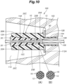
- Embodiment 7 of the prestressed concrete 100 will now be described with reference to Figure 10 .
- the parts corresponding to those in Figure 2 are denoted by the same reference numerals as the reference numerals in Figure 2 , and the description thereof will be omitted.
- the anchoring device 10 is mounted to each of the two ends of the concrete block 102 after molding and curing.
- a recess 112 having a truncated conical shape and opened to outside is molded at each of the two longitudinal end portions of the concrete block 102.
- Each recess 112 has an axial length greater than that of the anchoring device 10.
- a bottom surface 112A of each recess 112 forms a part of a substantial outer end surface of the concrete block 102.
- the anchoring device 10 is mounted to the concrete block 102 such that the inner end 12B of the barrel member 12 contacts the bottom surface 112A of the recess 112 via a patch plate 80 and the outer peripheral surface 12C of the barrel member 12 is exposed to outside.
- the entirety of the barrel member 12 is disposed in the recess 112.
- the anchoring devices 10 give a tension to the cable 106, whereby each anchoring device 10 is fixed to the concrete block 102 with the inner end 12B of the barrel member 12 being pressed against the patch plate 80 due to the tension.
- the prestressed concrete 100 of this embodiment allows for easy maintenance such as replacement of the anchoring device 10.
- recess 112 may be filled with mortar, asphalt, resin, or the like after arrangement of the anchoring device 10.
- the anchoring device 10 applied to the other embodiment shown in Figure 10 is not limited to the anchoring device 10 of Embodiment 1 and may be the anchoring device 10 of any of Embodiments 2 to 6.
- the barrel member 12 and the wedge member 20 may be composed of material other than resin, such as mortar, that is resistant to oxidation and corrosion.
- the barrel member 12 of Embodiments 2, 3, 5 and 6 may be made of resin containing no fibers.
- the wedge member 20, the spiral restraint body 60, and the annular restraint body 70 may be composed of material other than resin, such as titanium, that is resistant to oxidation and corrosion.
- the number of the wedge members 20 is not limited to two, and may be three or more.
- the wire may be a rod having flexibility.
- the anchoring device 10 is not limited to the one whose entirety is embedded in the concrete block 102, and may be adapted such that only a part on the side of the inner end 12B of the barrel member 12 is embedded in the concrete block 102 over a predetermined axial length.
Abstract
[Task] To provide a wedge-type anchoring device in which a barrel member does not cause a problem of corrosion, and which has sufficient strength against the diameter expansion deformation of the barrel member due to wedge action.[Solution] An anchoring device includes a barrel member 12 which is composed of resin or mortar and has a through hole 14 in a tapered shape, multiple wedge members 20 which each have an outer peripheral surface 20A having a tapered shape and slidably contacting an inner peripheral surface 14A of the through hole 14 and which cooperate with each other to grip a wire 110, and fibers 16 as a reinforcement member extending in a circumferential direction of the barrel member to suppress the diameter expansion deformation of the barrel member 12.
Description
- The present invention relates to an anchoring device and a prestressed concrete (PC), and more specifically relates to an anchoring device used to tension a wire in a prestressed concrete and the prestressed concrete.
- As an anchoring device used to tension a wire (cable, rod) in PC, there is known a wedge-type anchoring device including a barrel member (sleeve member) which is fixed to a PC concrete block and has a through hole having a tapered shape, and multiple wedge members which each have an outer peripheral surface having a tapered shape and slidably contacting an inner peripheral surface of the through hole and which cooperate with each other to grip the wire (for example, Patent Document 1).
- In this wedge-type anchoring device, the barrel member is fixed to the concrete block, and the end of the wire is gripped or anchored by the multiple wedge members according to wedge action of the wedge members being pushed into the tapered side of the through hole.
- Patent Document 1:
JPH11-210163 A - General wedge-type anchoring devices which are conventionally known may have a barrel member made of steel or a barrel member made of resin. Those with a barrel member made of steel have sufficient strength against diameter expansion deformation of the barrel member due to wedge action, but corrosion (rust) may occur depending on environmental conditions. Those with a barrel member made of resin do not cause corrosion but are difficult to have sufficient strength against the diameter expansion deformation of the barrel member due to wedge action.
- A task to be accomplished by the present invention is to provide a wedge-type anchoring device in which the barrel member does not corrode, and which has sufficient strength against the diameter expansion deformation of the barrel member due to wedge action.
- An anchoring device according to one embodiment of the present invention is an anchoring device (10) for an end of a wire (110), comprising: a barrel member (12) which is composed of resin or mortar and has a through hole (14) having a tapered shape; multiple wedge members (20) which each have an outer peripheral surface (20A) having a tapered shape and slidably contacting an inner peripheral surface (14A) of the through hole and which cooperate with each other to grip the wire; and a reinforcement member (16, 52, 60, 70) including a part that extends in a circumferential direction of the barrel member to suppress diameter expansion deformation of the barrel member.
- According to this configuration, the barrel member does not corrode, and sufficient strength against the diameter expansion deformation of the barrel member due to wedge action is provided.
- In the above-mentioned anchoring device, preferably, each wedge member is composed of resin or fiber reinforced resin.
- According to this configuration, the wedge members do not corrode.
- In the above-mentioned anchoring device, preferably, the reinforcement member comprises fibers (16, 52) embedded in the barrel member.
- According to this configuration, the barrel member and the reinforcement member can be integrally molded, which allows excellent productivity of the anchoring device.
- In the above-mentioned anchoring device, preferably, the barrel member is composed of a prepreg (42, 44, 46, 48) wound cylindrically so as to have an outer peripheral surface (42A, 44A, 46A, 48A) tapered in steps in a direction same as that of the tapered shape of the through hole, the prepreg comprises a base material (50) made of resin and fibers (52) impregnated in the base material, and the reinforcement member is composed of fibers comprised in the prepreg.
- According to this configuration, the barrel member including the reinforcement member is manufactured efficiently by using the prepreg, whereby the productivity is excellent. Further, the wall thickness of the barrel member can be made close to a uniform thickness over the entire length in the axial direction, and the barrel member can be made compact and lightweight.
- In the above-mentioned anchoring device, preferably, the prepreg is composed of multiple strip-shaped bodies disposed to overlap with each other in a radial direction at parts in an axial direction of the through hole.
- According to this configuration, the required shape of the barrel member is reliably formed by the prepreg.
- In the above-mentioned anchoring device, preferably, the reinforcement member comprises an annular body (30) provided on an outer circumference of the barrel member to surround the barrel member.
- According to this configuration, the diameter expansion of the barrel member is effectively suppressed by the annular body, whereby the diameter expansion deformation of the barrel member due to wedge action is effectively suppressed.
- In the above-mentioned anchoring device, preferably, the barrel member is composed of fiber reinforced resin, and the annular body is composed of fiber reinforced resin having a higher Young's modulus than the fiber reinforced resin composing the barrel member.
- According to this configuration, the diameter expansion deformation of the barrel member is reliably suppressed by the annular body, and in addition, the material cost is reduced compared to a case where the barrel member also is composed of fiber reinforced resin having a high Young's modulus.
- In the above-mentioned anchoring device, preferably, the annular body is provided partially in an axial direction of the through hole.
- According to this configuration, the material cost is reduced compared to a case where the annular body is provided over the entirety in the axial direction of the through hole.
- In the above-mentioned anchoring device, preferably, the annular body is provided continuously over an entirety in an axial direction of the through hole.
- According to this configuration, the diameter expansion deformation of the barrel member is reliably suppressed.
- In the above-mentioned anchoring device, preferably, the barrel member has an outer peripheral surface (12C) having a cylindrical shape, and the reinforcement member comprises a spiral restraint body (60) wound on the outer peripheral surface of the barrel member.
- According to this configuration, the diameter expansion of the barrel member is effectively suppressed by the spiral restraint body, whereby the diameter expansion deformation of the barrel member due to wedge action is effectively suppressed.
- In the above-mentioned anchoring device, preferably, the barrel member is composed of fiber reinforced resin, and the spiral restraint body is composed of fiber reinforced resin having a higher Young's modulus than the fiber reinforced resin composing the barrel member.
- According to this configuration, the diameter expansion deformation of the barrel member is reliably suppressed, and in addition, the material cost is reduced compared to a case where the barrel member also is composed of fiber reinforced resin having a high Young's modulus.
- In the above-mentioned anchoring device, preferably, the barrel member has a spiral groove (12D) on the outer peripheral surface, and the spiral restraint body is fitted in the spiral groove.
- According to this configuration, axial movement of the spiral restraint body relative to the barrel member is suppressed, and the effect of the spiral restraint body of suppressing the diameter expansion deformation of the barrel member becomes stable.
- In the above-mentioned anchoring device, preferably, the barrel member has an outer peripheral surface (12E) having a conical shape, and the reinforcement member comprises an annular restraint body (70) fitted on the outer peripheral surface of the barrel member.
- According to this configuration, the annular restraint body acts to suppress the diameter expansion of the barrel member, whereby the diameter expansion deformation of the barrel member due to wedge action is suppressed.
- In the above-mentioned anchoring device, preferably, the barrel member is composed of fiber reinforced resin, and the annular restraint body is composed of fiber reinforced resin having a higher Young's modulus than the fiber reinforced resin composing the barrel member.
- According to this configuration, the diameter expansion deformation of the barrel member is reliably suppressed, and in addition, the material cost is reduced compared to a case where the barrel member also is composed of fiber reinforced resin having a high Young's modulus.
- In the above-mentioned anchoring device, preferably, an end surface (70B) of the annular restraint body on a tapered side of the conical shape of the barrel member includes a surface perpendicular to an axial direction of the barrel member.
- According to this configuration, in a state in which the barrel member is embedded in a concrete block of prestressed concrete, axial movement of the barrel member relative to the concrete block is suppressed, and operation of the anchoring device in the prestressed concrete becomes stable.
- A prestressed concrete according to one embodiment of the present invention comprises: a concrete block having a rectangular parallelepiped shape; a wire penetrating in a longitudinal direction of the concrete block; and the anchoring device according to the above-described embodiment which is provided at each of two end portions of the concrete block in the longitudinal direction and to which an end portion of the wire is locked.
- According to this configuration, a stable prestressed state is maintained over an extended period of time and excellent durability is obtained.
- In the above-mentioned prestressed concrete, the anchoring device may either be embedded in the concrete block or be mounted to the concrete block such that one end surface (12B) of the barrel member contacts an end surface of the concrete block and an outer peripheral surface (12C, 12E) of the barrel member is exposed to outside.
- In the anchoring device according to the present invention, corrosion of the barrel member does not occur, and sufficient strength against the diameter expansion deformation of the barrel member due to wedge action is provided.
-
-
Figure 1 is a sectional view showing Embodiment 1 of a prestressed concrete and an anchoring device according to the present invention; -
Figure 2 is a sectional view of a main part of a prestressed concrete having an anchoring device according to Embodiment 1; -
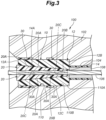
Figure 3 is a sectional view of a main part of a prestressed concrete having an anchoring device according to Embodiment 2; -
Figure 4 is a sectional view of a main part of a prestressed concrete having an anchoring device according to Embodiment 3; -
Figure 5 is a sectional view of a main part of a prestressed concrete having an anchoring device according to Embodiment 4; -
Figure 6 is a sectional view showing a manufacturing process of a barrel member of the anchoring device according to Embodiment 4; -
Figure 7 is a partial sectional view of a main part of a prestressed concrete having an anchoring device according to Embodiment 5; -
Figure 8 is a sectional view of the main part of the prestressed concrete having the anchoring device according to Embodiment 5; -
Figure 9 is a partial sectional view of a main part of a prestressed concrete having an anchoring device according to Embodiment 6; and -
Figure 10 is a sectional view showing Embodiment 7 of the prestressed concrete and the anchoring device according to the present invention. - As shown in
Figure 1 , aprestressed concrete 100 includes aconcrete block 102 molded in a rectangular parallelepiped shape, acylindrical sheath 104 made of resin and embedded in theconcrete block 102 to extend in the longitudinal direction of theconcrete block 102, and a cable (wire) 106 composed of fiber reinforced resin or metal and disposed in thesheath 104 to penetrate theconcrete block 102 in the longitudinal direction. A space between thesheath 104 and thecable 106 is filled withgrout 108 consisting of cement mortar or the like. - The
prestressed concrete 100 further includes left andright anchoring devices 10 which are provided at both longitudinal end portions of the concrete block 102 (left and right end portions as seen inFigure 1 ) and to which the end portions of thecable 106 are locked. The left andright anchoring devices 10 sandwich theconcrete block 102 from both sides in the longitudinal direction and fix (anchor) thecable 106 in theconcrete block 102 to be in a state of tension. Thereby, prestress is given to theconcrete block 102. - The left and
right anchoring devices 10 are of a wedge type and each include acylindrical barrel member 12 and a pair of upper andlower wedge members 20 as seen inFigure 1 . Since the left andright anchoring devices 10 have the same structure, in the following, description will be made taking theanchoring device 10 disposed on the left side as an example. - As shown in
Figure 2 , thebarrel member 12 includes anouter end 12A exposed to outside from theconcrete block 102, aninner end 12B joined to anend surface 110A of an anchoringdevice embedding hole 110 of theconcrete block 102, and an outerperipheral surface 12C joined to an innerperipheral surface 110B of the anchoringdevice embedding hole 110, and the entirety of thebarrel member 12 is embedded in an end portion of theconcrete block 102. - Thereby, the
barrel member 12 is fixed to theconcrete block 102 so as not to be displaceable both in the axial direction (the left-right direction as seen inFigure 2 ), which is a direction of prestress application to theconcrete block 102 and in the radial direction. The embedding of thebarrel member 12 in theconcrete block 102 may be performed when theconcrete block 102 is molded. By molding theconcrete block 102 with the anchoringdevice 10 being an insert member, the anchoringdevice embedding hole 110 is formed when theconcrete block 102 is molded. - The
barrel member 12 has a throughhole 14 extending through a central part thereof in the axial direction. The throughhole 14 is a hole having a tapered shape extending from theouter end 12A to theinner end 12B of thebarrel member 12, with both ends open. In other words, the throughhole 14 is a tapered hole having an inner diameter gradually decreasing from theouter end 12A to theinner end 12B of thebarrel member 12. - The
barrel member 12 is a molded product made of resin such as epoxy resin, polyester resin, or the like. As shown inFigure 2(A) , thebarrel member 12 has mesh-like or sheet-like fibers 16 embedded therein. Thefibers 16 may be glass fibers, carbon fibers, boron fibers, aramid fibers, basalt fibers, or the like, and are present in thebarrel member 12 in a form wound cylindrically around the central axis of the throughhole 14 to form multiple layers. Thereby, thefibers 16 constitute a reinforcement member including a part that continuously extends in the circumferential direction of thebarrel member 12. - Note that, as shown in
Figure 2 (B) , thefibers 16 may be a bundle of fibers wound multiple times around the central axis of the throughhole 14 in form of helices with different diameters. In this case also, thefibers 16 constitute a reinforcement member continuously extending in the circumferential direction of thebarrel member 12. - In either case, the
fibers 16 increases an apparent tensile strength and Young's modulus (longitudinal elastic modulus) of thebarrel member 12 in the diameter expansion direction and thereby suppresses the diameter expansion deformation of thebarrel member 12. To effectively suppress the diameter expansion deformation of thebarrel member 12, it is preferred that thefibers 16 include a part continuously extending around the central axis of the throughhole 14, but may be discontinuous depending on the required tensile strength and Young's modulus of thebarrel member 12 in the radial direction. - Each
wedge member 20 is a molded product made of resin or fiber reinforced resin, has a shape formed by dividing a tapered rod in half, and has an outerperipheral surface 20A having a tapered shape and slidably contacting the innerperipheral surface 14A of the throughhole 14 and acable groove 20B having a substantially semicircular cross-sectional shape and opened in ahalved surface 20C. - The two
wedge members 20 cooperate with each other to grip an end of thecable 106 engaged with thecable groove 20B and in the state of tension, and are pressed toward the tapered side of the throughhole 14, in other words, are driven into the tapered side of the throughhole 14, to increase the friction resistance against thecable 106 due to wedge action with respect to thebarrel member 12 and to lock (anchor) the end of thecable 106 to theconcrete block 102 via thebarrel member 12. - As a result of the wedge action mentioned above, a load urging the
barrel member 12 to undergo diameter expansion deformation acts on thebarrel member 12. In this state, thefibers 16 act as a reinforcement member to suppress the diameter expansion deformation of thebarrel member 12. - Accordingly, even though the
barrel member 12 is composed of resin instead of steel to prevent rust, thebarrel member 12 is provided with sufficient strength against the diameter expansion deformation due to wedge action, and thus, reduction of wedge action is prevented. - As described above, with the anchoring
device 10 of Embodiment 1, thebarrel member 12 does not corrode even when used over an extended period of time, and sufficient strength against the diameter expansion deformation of thebarrel member 12 due to wedge action is provided, whereby lowering of the anchoring strength of thecable 106 due to the diameter expansion deformation of thebarrel member 12 is prevented. Since thewedge member 20 also is a molded product made of resin or fiber reinforced resin, thewedge member 20 does not corrode in use over an extended period of time. - In the
anchoring device 10 of Embodiment 1, as a result of molding of thebarrel member 12 containing thefibers 16, thefibers 16 and the barrel member 12 (base material) are integrally molded, which allows excellent productivity of theanchoring device 10. - An
anchoring device 10 of Embodiment 2 will now be described with reference toFigure 3 . Note that inFigure 3 , the parts corresponding to those inFigure 2 are denoted by the same reference numerals as the reference numerals inFigure 2 , and the description thereof will be omitted. - In Embodiment 2, multiple
annular bodies 30 are provided on the outer circumference of thecylindrical barrel member 12 at a predetermined interval in the extension direction (axial direction) of the throughhole 14. As seen in the axial direction of the throughhole 14, the multipleannular bodies 30 are partially provided on thebarrel member 12. Eachannular body 30 has an annular shape continuously extends around the outer circumference of thebarrel member 12, namely, is provided to completely surround the outer circumference of thebarrel member 12. Eachannular body 30 is integrally molded with thebarrel member 12 or retrofitted on thebarrel member 12. - The
annular body 30 is composed of fiber reinforced resin. The fibers (not shown in the drawings) contained in the fiber reinforced resin may be glass fibers, carbon fibers, boron fibers, aramid fibers, basalt fibers, or the like. These fibers may be mesh-like or sheet-like fibers wound cylindrically around the central axis of the throughhole 14 to form multiple layers, and include a part continuously extending in the circumferential direction of thebarrel member 12. - The fibers (not shown in the drawings) contained in each
annular body 30 may be a bundle of fibers wound multiple times around the central axis of the throughhole 14 in form of helices with different diameters. In this case also, the fibers contained in theannular body 30 include a part continuously extending in the circumferential direction of thebarrel member 12. - In addition to the
fibers 16 embedded in thebarrel member 12, eachannular body 30 acts as a reinforcement member that suppresses the diameter expansion deformation of thebarrel member 12, and this makes thebarrel member 12 difficult to undergo diameter expansion deformation even further. - Each
annular body 30 may be composed of fiber reinforced resin containing high-tensile fibers having a Young's modulus and a tensile strength higher than those of thefibers 16 embedded in thebarrel member 12, such as carbon fiber reinforced resin and the like. In other words, eachannular body 30 is composed of fiber reinforced resin having a higher Young's modulus than the fiber reinforced resin composing thebarrel member 12. With the high-tensile fibers contained in the fiber reinforced resin, eachannular body 30 exerts a reinforcing effect to suppress diameter expansion deformation of thebarrel member 12. - Therefore, even when the
anchoring device 10 of Embodiment 2 is used over an extended period of time, thebarrel member 12 does not corrode. In addition, thebarrel member 12 is provided with sufficient strength against the diameter expansion deformation due to wedge action, whereby lowering of the anchoring strength of thecable 106 due to the diameter expansion deformation of thebarrel member 12 is prevented. - Even though the
fibers 16 embedded in thebarrel member 12 and the fibers in the fiber reinforced resin composing theannular bodies 30 are composed of different materials and thefibers 16 are composed of glass fibers cheaper than carbon fibers or the like contained in theannular bodies 30, strength similar to when thebarrel member 12 is composed of expensive carbon fiber reinforced resin or the like (strength that suppresses the diameter expansion deformation of the barrel member 12) is obtained due to the high reinforcing effect of eachannular body 30. Therefore, the material cost of thebarrel member 12 is saved (reduced), and in addition, the diameter expansion deformation of thebarrel member 12 is effectively suppressed. - Also, since each
annular body 30 is partially provided in the axial direction of thebarrel member 12, the material cost of theannular bodies 30 is reduced compared to a case where anannular body 30 is provided continuously over the entire length of thebarrel member 12. - When embedded in the
concrete block 102 with thebarrel member 12, anannular end surface 30A of eachannular body 30 is joined to theconcrete block 102. This enhances the bonding strength between thebarrel member 12 and theconcrete block 102. In other words, theend surface 30A of eachannular body 30 functions as a barrier surface that prevents thebarrel member 12 from moving in the axial direction relative to theconcrete block 102. - Due to this function, axial movement of the
barrel member 12 relative to theconcrete block 102 is effectively suppressed. As a result of this, the high-qualityprestressed concrete 100 to which stable prestress is applied over an extended period of time is manufactured with excellent productivity without requiring additional components and steps. - An
anchoring device 10 of Embodiment 3 will now be described with reference toFigure 4 . Note that inFigure 4 , the parts corresponding to those inFigure 3 are denoted by the same reference numerals as the reference numerals inFigure 3 , and the description thereof will be omitted. - In Embodiment 3, the
annular body 30 is composed of a cylindrical body having a substantially same axial length as the axial length of thebarrel member 12 and provided on the outer circumference of thebarrel member 12. - To effectively suppress the diameter expansion deformation of the
barrel member 12, the fibers contained in theannular body 30 preferably include a part continuously extending around the central axis of the throughhole 14. These fibers may be mesh-like or sheet-like fibers wound in the circumferential direction, may be wound in two directions of the circumferential direction and the axial direction and pasted together, or may be woven in two directions and wound. - In this embodiment also, the
annular body 30 may be composed of fiber reinforced resin containing high-tensile fibers having a Young's modulus and a tensile strength higher than those of thefibers 16 embedded in thebarrel member 12, such as carbon fiber reinforced resin and the like. In other words, in this embodiment also, theannular body 30 is composed of fiber reinforced resin having a higher Young's modulus than the fiber reinforced resin composing thebarrel member 12. - In this embodiment also, even though the
fibers 16 embedded in thebarrel member 12 and the fibers in the fiber reinforced resin composing theannular bodies 30 are composed of different materials and thefibers 16 are composed of glass fibers cheaper than carbon fibers or the like contained in theannular bodies 30, strength similar to when thebarrel member 12 is composed of expensive carbon fiber reinforced resin or the like (strength that suppresses the diameter expansion deformation of the barrel member 12) is obtained due to the high reinforcing effect of eachannular body 30. Therefore, the material cost of thebarrel member 12 is reduced, and in addition, the diameter expansion deformation of thebarrel member 12 is effectively suppressed. - In Embodiment 3, the effect of suppressing the diameter expansion deformation of the
barrel member 12 by theannular body 30 is obtained substantially uniformly over the entirety of the axial length of thebarrel member 12. - Thus, with the anchoring
device 10 of Embodiment 3, thebarrel member 12 does not corrode even when used over an extended period of time, and sufficient strength against the diameter expansion deformation of thebarrel member 12 due to wedge action is provided, whereby lowering of the anchoring strength of thecable 106 due to the diameter expansion deformation of thebarrel member 12 is prevented. - An
anchoring device 10 of Embodiment 4 will now be described with reference toFigures 5 and6 . Note that inFigures 5 and6 , the parts corresponding to those inFigure 2 are denoted by the same reference numerals as the reference numerals inFigure 2 , and the description thereof will be omitted. - As shown in
Figure 5 , thebarrel member 12 is composed of multiple strip-shapedprepregs peripheral surfaces hole 14. - In other words, the outer winding diameters of the
prepregs prepreg 48 which is positioned on the side of theouter end 12A of thebarrel member 12 to theprepreg 42 which is positioned on the side of theinner end 12B. - As shown in
Figure 6 , thebarrel member 12 is manufactured from an assembly 40 in which theprepregs barrel member 12 is obtained by forming the throughhole 14 by cutting after curing of theprepregs - As shown in
Figure 5(A) , theprepregs fibers 52 in a matrix (base material) 50 such as epoxy resin. Thefibers 52 may be glass fibers, carbon fibers, boron fibers, aramid fibers, basalt fibers, or the like. - The
fibers 52 are mesh-like or sheet-like fibers and are present in thematrix 50 in a form wound cylindrical around the central axis of the throughhole 14 to form multiple layers. Thereby, thefibers 52 constitute a reinforcement member including a part continuously extending in the circumferential direction of thebarrel member 12 composed of thematrix 50. - Note that, as shown in
Figure 5(B) , thefibers 52 may be a bundle of fibers wound multiple times around the central axis of the throughhole 14 in form of helices with different diameters. In this case also, thefibers 52 constitute a reinforcement member continuously extending in the circumferential direction of thebarrel member 12. - In Embodiment 4 also, similarly to Embodiment 1, a load urging the
barrel member 12 to undergo diameter expansion deformation acts on thebarrel member 12 due to wedge action resulting from the driving of thewedge members 20. In this state, thefibers 52 act as a reinforcement member to suppress the diameter expansion deformation of thebarrel member 12. - Accordingly, even though the
barrel member 12 is composed of matrix resin instead of steel to prevent rust, thebarrel member 12 is provided with sufficient strength against the diameter expansion deformation due to wedge action, and thus, reduction of wedge action is prevented. - As described above, with the anchoring
device 10 of Embodiment 4, thebarrel member 12 does not corrode even when used over an extended period of time, and sufficient strength against the diameter expansion deformation of thebarrel member 12 due to wedge action is provided, whereby lowering of the anchoring strength of thecable 106 due to the diameter expansion deformation of thebarrel member 12 is prevented. - In Embodiment 4, the
barrel member 12 including the reinforcement member is manufactured efficiently by using theprepregs prepregs hole 14, thebarrel member 12 having a predetermined shape is reliably formed by theprepregs - Also, in the
anchoring device 10 of Embodiment 4, thebarrel member 12 has a shape tapered in steps in the same direction as the throughhole 14 due to the outerperipheral surfaces respective prepregs barrel member 12 is smaller than in Embodiment 1. - Thus, the
barrel member 12 is manufactured efficiently by using theprepregs barrel member 12 can be made close to a uniform thickness over the entire length in the axial direction. Further, the wall thickness of thebarrel member 12 can be made close to the minimum required thickness over the entire axial length, and thebarrel member 12 can be made compact and lightweight. - Also, in the state embedded in the
concrete block 102, end surfaces 42B, 44B, 46B, 48B of the curedprepregs inner end 12B function as barrier surfaces that enhance the bonding strength between thebarrel member 12 and theconcrete block 102 and prevent thebarrel member 12 from moving in the axial direction (rightward) relative to theconcrete block 102. - Therefore, movement of the
barrel member 12 in the axial direction (right direction) relative to theconcrete block 102 is effectively suppressed. As a result of this, the high-qualityprestressed concrete 100 to which stable prestress is applied over an extended period of time is manufactured with excellent productivity without requiring additional components and steps. - An
anchoring device 10 of Embodiment 5 will now be described with reference toFigures 7 and8 . Note that inFigures 7 and8 , the parts corresponding to those inFigure 2 are denoted by the same reference numerals as the reference numerals inFigure 2 , and the description thereof will be omitted. - The
barrel member 12 is a cylindrical molded product made of fiber reinforced resin composed of matrix resin such as epoxy resin, polyester resin, or the like and fibers such as glass fibers, carbon fibers, boron fibers, aramid fibers, basalt fibers, or the like, and is molded in a cylindrical shape having a throughhole 14. Thebarrel member 12 may be a product similar to thebarrel member 12 of Embodiment 1. - The outer
peripheral surface 12C of thebarrel member 12 is formed with aspiral groove 12D having a semi-circular cross section with a predetermined pitch substantially over the entire length of the axial direction of thebarrel member 12. In thespiral groove 12D, aspiral restraint body 60 having a circular cross section is fitted. Thespiral restraint body 60 is a molded product made of fiber reinforced resin composed of matrix resin such as epoxy resin, polyester resin, or the like and fibers such as glass fibers, carbon fibers, boron fibers, aramid fibers, basalt fibers, steel fibers, or the like. - Therefore, the
spiral restraint body 60 is wound on the outerperipheral surface 12C of thebarrel member 12 and constitutes a reinforcement member including a part extending in the circumferential direction of thebarrel member 12. Since thespiral restraint body 60 is fitted in thespiral groove 12D, thespiral restraint body 60 does not shift relative to thebarrel member 12 at such time as when manufacturing theconcrete block 102, and the placement position of thespiral restraint body 60 with respect to thebarrel member 12 does not fluctuate. This stabilizes the effect of suppression of the diameter expansion deformation of thebarrel member 12 by thespiral restraint body 60. - The fitting of the
spiral restraint body 60 to thespiral groove 12D may be achieved by moving thespiral restraint body 60 in the axial direction relative to thebarrel member 12 from the side of one end of thebarrel member 12, with thespiral restraint body 60 deformed to have an expanded diameter such that the inner diameter of thespiral restraint body 60 is larger than the outer diameter of thebarrel member 12, and releasing the diameter expansion deformation at a position where thespiral restraint body 60 aligns with thespiral groove 12D in the axial direction, or by making thespiral groove 12D threadedly engaged with thespiral restraint body 60 from the side of one end of thebarrel member 12 while rotating thespiral restraint body 60 relative to thebarrel member 12. - In Embodiment 5 also, similarly to Embodiment 1, a load urging the
barrel member 12 to undergo diameter expansion deformation acts on thebarrel member 12 due to wedge action resulting from the driving of thewedge members 20. In this state, thespiral restraint body 60 acts as a reinforcement member to suppress the diameter expansion deformation of thebarrel member 12. To properly obtain this effect, preferably, thespiral restraint body 60 is fitted in thespiral groove 12D in a preloaded state. - Accordingly, even though the
barrel member 12 is composed of matrix resin instead of steel to prevent rust, thebarrel member 12 is provided with sufficient strength against the diameter expansion deformation due to wedge action, and thus, reduction of wedge action is prevented. - As described above, with the anchoring
device 10 of Embodiment 5, the diameter expansion deformation of thebarrel member 12 is effectively suppressed by thespiral restraint body 60. Accordingly, thebarrel member 12 does not corrode even when used over an extended period of time, while thebarrel member 12 is provided with sufficient strength against the diameter expansion deformation due to wedge action, whereby lowering of the anchoring strength of thecable 106 due to the diameter expansion deformation of thebarrel member 12 is effectively prevented. - The
spiral restraint body 60 may be composed of high-tensile fiber reinforced resin having a Young's modulus and a tensile strength higher than those of thebarrel member 12. In other words, thespiral restraint body 60 is composed of fiber reinforced resin having a higher Young's modulus than the fiber reinforced resin composing thebarrel member 12. - In this case, even though the
barrel member 12 is composed of reinforced resin containing glass fibers cheaper than carbon fibers or the like, strength similar to when thebarrel member 12 is composed of carbon fiber reinforced resin or the like (strength that suppresses the diameter expansion deformation of the barrel member 12) is obtained due to the reinforcing effect of thespiral restraint body 60. Therefore, the diameter expansion deformation of thebarrel member 12 is effectively suppressed, and the material cost of thebarrel member 12 is saved. - An
anchoring device 10 of Embodiment 6 will now be described with reference toFigure 9 . Note that inFigure 9 , the parts corresponding to those inFigure 2 are denoted by the same reference numerals as the reference numerals inFigure 2 , and the description thereof will be omitted. - The
barrel member 12 is a molded product made of fiber reinforced resin composed of matrix resin such as epoxy resin, polyester resin, or the like and fibers such as glass fibers, carbon fibers, boron fibers, aramid fibers, basalt fibers, or the like, and is molded in a truncated conical shape having a throughhole 14. An outerperipheral surface 12E of thebarrel member 12 consists of a conical surface (tapered surface) having an outer diameter gradually diminishing from theouter end 12A to theinner end 12B. In other words, thebarrel member 12 has a conical shape tapered in the same direction as the throughhole 14. - On the outer
peripheral surface 12E of thebarrel member 12, multipleannular restraint bodies 70 are mounted at intervals in the axial direction. Eachannular restraint body 70 is a molded product made of fiber reinforced resin composed of matrix resin such as epoxy resin, polyester resin, or the like and fibers such as glass fibers, carbon fibers, boron fibers, aramid fibers, basalt fibers, steel fibers, or the like. - Each
annular restraint body 70 has an inner peripheral surface 70A in a tapered shape matching the outerperipheral surface 12E of thebarrel member 12, and the inner peripheral surface 70A is fitted on the outerperipheral surface 12E of thebarrel member 12 so as not to be displaceable in the axial direction of thebarrel member 12. - An
end surface 70B of eachannular restraint body 70 on the tapered side of the conical shape of the barrel member 12 (right side in the drawing) consists of a surface perpendicular to the axial direction of thebarrel member 12. - In Embodiment 5 also, similarly to Embodiment 1, a load urging the
barrel member 12 to undergo diameter expansion deformation acts on thebarrel member 12 due to wedge action resulting from the driving of thewedge members 20. In this state, eachannular restraint body 70 acts as a reinforcement member to suppress the diameter expansion deformation of thebarrel member 12. - Accordingly, even though the
barrel member 12 is composed matrix resin instead of steel to prevent rust, thebarrel member 12 is provided with sufficient strength against the diameter expansion deformation due to wedge action, and thus, reduction of wedge action is prevented. - As described above, with the anchoring
device 10 of Embodiment 5, the diameter expansion deformation of thebarrel member 12 is effectively suppressed by theannular restraint bodies 70. Accordingly, thebarrel member 12 does not corrode even when used over an extended period of time, whilebarrel member 12 is provided with sufficient strength against the diameter expansion deformation due to wedge action, whereby lowering of the anchoring strength of thecable 106 due to the diameter expansion deformation of thebarrel member 12 is effectively prevented. - Each
annular restraint body 70 may be composed of high-tensile fiber reinforced resin having a Young's modulus and a tensile strength higher than those of thebarrel member 12. In other words, eachannular restraint body 70 is composed of fiber reinforced resin having a higher Young's modulus than the fiber reinforced resin composing thebarrel member 12. - In this case, even though the
barrel member 12 is composed of reinforced resin containing glass fibers cheaper than carbon fibers or the like, strength similar to when thebarrel member 12 is composed of carbon fiber reinforced resin or the like (strength that suppresses the diameter expansion deformation of the barrel member 12) is obtained due to the reinforcing effect of eachannular restraint body 70. Therefore, the diameter expansion deformation of thebarrel member 12 is effectively suppressed, and the material cost of thebarrel member 12 is saved. - Since the
barrel member 12 has a conical shape tapered in the same direction as the throughhole 14, movement of thebarrel member 12 in the axial direction (rightward) relative to theconcrete block 102 is suppressed, and the high-quality concrete block 102 to which stable prestress is applied over an extended period of time is obtained. - Further, in the state embedded in the
concrete block 102, eachannular restraint body 70 enhances the bonding strength between thebarrel member 12 and theconcrete block 102, and theend surface 70B of eachannular restraint body 70 functions as a barrier surface that prevents movement of thebarrel member 12 in the axial direction (rightward) relative to theconcrete block 102. - Due to this function, axial movement of the
barrel member 12 relative to theconcrete block 102 is effectively suppressed. As a result of this, the high-qualityprestressed concrete 100 to which stable prestress is applied over an extended period of time is manufactured with excellent productivity without requiring additional components and steps. - Embodiment 7 of the
prestressed concrete 100 will now be described with reference toFigure 10 . Note that inFigure 10 , the parts corresponding to those inFigure 2 are denoted by the same reference numerals as the reference numerals inFigure 2 , and the description thereof will be omitted. - In this embodiment, the anchoring
device 10 is mounted to each of the two ends of theconcrete block 102 after molding and curing. - More specifically, a
recess 112 having a truncated conical shape and opened to outside is molded at each of the two longitudinal end portions of theconcrete block 102. Eachrecess 112 has an axial length greater than that of theanchoring device 10. Abottom surface 112A of eachrecess 112 forms a part of a substantial outer end surface of theconcrete block 102. - The anchoring
device 10 is mounted to theconcrete block 102 such that theinner end 12B of thebarrel member 12 contacts thebottom surface 112A of therecess 112 via apatch plate 80 and the outerperipheral surface 12C of thebarrel member 12 is exposed to outside. In this embodiment, the entirety of thebarrel member 12 is disposed in therecess 112. - The
anchoring devices 10 give a tension to thecable 106, whereby each anchoringdevice 10 is fixed to theconcrete block 102 with theinner end 12B of thebarrel member 12 being pressed against thepatch plate 80 due to the tension. - The
prestressed concrete 100 of this embodiment allows for easy maintenance such as replacement of theanchoring device 10. - Note that the
recess 112 may be filled with mortar, asphalt, resin, or the like after arrangement of theanchoring device 10. - The anchoring
device 10 applied to the other embodiment shown inFigure 10 is not limited to theanchoring device 10 of Embodiment 1 and may be the anchoringdevice 10 of any of Embodiments 2 to 6. - In the foregoing, the present invention has been described in terms of preferred embodiments thereof. However, as will be readily appreciated by a person of ordinary skill in the art, the present invention is not limited to such embodiments and may be modified appropriately within the spirit of the present invention.
- For example, the
barrel member 12 and thewedge member 20 may be composed of material other than resin, such as mortar, that is resistant to oxidation and corrosion. Thebarrel member 12 of Embodiments 2, 3, 5 and 6 may be made of resin containing no fibers. Thewedge member 20, thespiral restraint body 60, and theannular restraint body 70 may be composed of material other than resin, such as titanium, that is resistant to oxidation and corrosion. The number of thewedge members 20 is not limited to two, and may be three or more. Instead of thecable 106, the wire may be a rod having flexibility. The anchoringdevice 10 is not limited to the one whose entirety is embedded in theconcrete block 102, and may be adapted such that only a part on the side of theinner end 12B of thebarrel member 12 is embedded in theconcrete block 102 over a predetermined axial length. - Also, not all of the components shown in the above embodiments are necessarily indispensable and they may be selectively adopted as appropriate without departing from the spirit of the present invention.
-
- 10:
- anchoring device
- 12:
- barrel member
- 12A:
- outer end
- 12B:
- inner end
- 12C:
- outer peripheral surface
- 12D:
- spiral groove
- 12E:
- outer peripheral surface
- 14:
- through hole
- 14A:
- inner peripheral surface
- 16:
- fibers
- 20:
- wedge member
- 20A:
- outer peripheral surface
- 20B:
- cable the groove
- 20C:
- half-split surface
- 30:
- annular body
- 30A:
- end surface
- 40:
- assembly
- 42:
- prepreg
- 42A:
- outer peripheral surface
- 42B:
- end surface
- 44:
- prepreg
- 44A:
- outer peripheral surface
- 44B:
- end surface
- 46:
- prepreg
- 46A:
- outer peripheral surface
- 46B:
- end surface
- 48:
- prepreg
- 48A:
- outer peripheral surface
- 48B:
- end surface
- 50:
- matrix
- 52:
- fibers
- 60:
- spiral restraint body
- 70:
- annular restraint body
- 70A:
- inner peripheral surface
- 70B:
- end surface
- 80:
- patch plate
- 100:
- prestressed concrete
- 102:
- concrete block
- 104:
- sheath
- 106:
- cable
- 108:
- grout
- 110:
- anchoring device embedding hole
- 110A:
- end surface
- 110B:
- inner peripheral surface
- 112:
- recess
- 112A:
- bottom surface
Claims (18)
- An anchoring device for an end of a wire, comprising:a barrel member which is composed of resin or mortar and has a through hole having a tapered shape;multiple wedge members which each have an outer peripheral surface having a tapered shape and slidably contacting an inner peripheral surface of the through hole and which cooperate with each other to grip the wire; anda reinforcement member including a part that extends in a circumferential direction of the barrel member.
- The anchoring device according to claim 1, wherein each wedge member is composed of resin or fiber reinforced resin.
- The anchoring device according to claim 1 or 2, wherein the reinforcement member comprises fibers embedded in the barrel member.
- The anchoring device according to claim 1 or 2, wherein the barrel member is composed of a prepreg wound cylindrically so as to have an outer peripheral surface tapered in steps in a direction same as that of the tapered shape of the through hole,the prepreg comprises a base material made of resin and fibers impregnated in the base material, andthe reinforcement member is composed of the fibers comprised in the prepreg.
- The anchoring device according to claim 4, wherein the prepreg is composed of multiple strip-shaped bodies disposed to overlap with each other in a radial direction at parts in an axial direction of the through hole.
- The anchoring device according to any one of claims 1 to 5, wherein the reinforcement member comprises an annular body provided on an outer circumference of the barrel member to surround the barrel member.
- The anchoring device according to claim 6, wherein the barrel member is composed of fiber reinforced resin, and
the annular body is composed of fiber reinforced resin having a higher Young's modulus than the fiber reinforced resin composing the barrel member. - The anchoring device according to claim 6 or 7, wherein the annular body is provided partially in an axial direction of the through hole.
- The anchoring device according to claim 6 or 7, wherein the annular body is provided continuously over an entirety in an axial direction of the through hole.
- The anchoring device according to claim 1 or 2, wherein the barrel member has an outer peripheral surface having a cylindrical shape, and
the reinforcement member comprises a spiral restraint body wound on the outer peripheral surface of the barrel member. - The anchoring device according to claim 10, wherein the barrel member is composed of fiber reinforced resin, and
the spiral restraint body is composed of fiber reinforced resin having a higher Young's modulus than the fiber reinforced resin composing the barrel member. - The anchoring device according to claim 10 or 11, wherein the barrel member has a spiral groove on the outer peripheral surface, and
the spiral restraint body is fitted in the spiral groove. - The anchoring device according to claim 1 or 2, wherein the barrel member has an outer peripheral surface having a conical shape, and
the reinforcement member comprises an annular restraint body fitted on the outer peripheral surface of the barrel member. - The anchoring device according to claim 13, wherein the barrel member is composed of fiber reinforced resin, and
the annular restraint body is composed of fiber reinforced resin having a higher Young's modulus than the fiber reinforced resin composing the barrel member. - The anchoring device according to claim 13 or 14, wherein an end surface of the annular restraint body on a tapered side of the conical shape of the barrel member includes a surface perpendicular to an axial direction of the barrel member.
- A prestressed concrete, comprising:a concrete block having a rectangular parallelepiped shape;a wire penetrating in a longitudinal direction of the concrete block; andthe anchoring device according to any one of claims 1 to 15 which is provided at each of two end portions of the concrete block in the longitudinal direction and to which an end portion of the wire is locked.
- The prestressed concrete according to claim 16, wherein the anchoring device is embedded in the concrete block.
- The prestressed concrete according to claim 16, wherein the anchoring device is mounted to the concrete block such that one end surface of the barrel member contacts an end surface of the concrete block and an outer peripheral surface of the barrel member is exposed to outside.
Applications Claiming Priority (2)
| Application Number | Priority Date | Filing Date | Title |
|---|---|---|---|
| JP2020208553 | 2020-12-16 | ||
| PCT/JP2021/045668 WO2022131174A1 (en) | 2020-12-16 | 2021-12-10 | Fixing implement and pre-stressed concrete |
Publications (1)
| Publication Number | Publication Date |
|---|---|
| EP4265863A1 true EP4265863A1 (en) | 2023-10-25 |
Family
ID=82057806
Family Applications (1)
| Application Number | Title | Priority Date | Filing Date |
|---|---|---|---|
| EP21906536.4A Pending EP4265863A1 (en) | 2020-12-16 | 2021-12-10 | Fixing implement and pre-stressed concrete |
Country Status (5)
| Country | Link |
|---|---|
| US (1) | US20240093494A1 (en) |
| EP (1) | EP4265863A1 (en) |
| JP (1) | JPWO2022131174A1 (en) |
| TW (1) | TW202237952A (en) |
| WO (1) | WO2022131174A1 (en) |
Families Citing this family (1)
| Publication number | Priority date | Publication date | Assignee | Title |
|---|---|---|---|---|
| CN115262547A (en) * | 2022-08-24 | 2022-11-01 | 铁科院(深圳)特种工程有限公司 | Side slope protective net construction method based on assembly type anchoring structure |
Family Cites Families (6)
| Publication number | Priority date | Publication date | Assignee | Title |
|---|---|---|---|---|
| JPH0625457B2 (en) * | 1987-11-02 | 1994-04-06 | 三菱マテリアル株式会社 | Fixing tool for prestressed concrete and fixing method |
| JPH0438354A (en) * | 1990-06-01 | 1992-02-07 | Kajima Corp | Stretching method for frp rod |
| JPH11210163A (en) | 1998-01-28 | 1999-08-03 | Ps:Kk | Anchor of frp tensioner |
| JP5217054B2 (en) * | 2007-03-02 | 2013-06-19 | 住友電工スチールワイヤー株式会社 | Strand |
| JP6546829B2 (en) * | 2015-10-19 | 2019-07-17 | 槌屋ティスコ株式会社 | Fiber-reinforced resin rod and method of manufacturing the same |
| JP6770783B2 (en) * | 2016-08-08 | 2020-10-21 | 三井住友建設株式会社 | How to attach the intermediate fixing tool and the intermediate fixing tool |
-
2021
- 2021-12-10 US US18/257,174 patent/US20240093494A1/en active Pending
- 2021-12-10 JP JP2022569958A patent/JPWO2022131174A1/ja active Pending
- 2021-12-10 WO PCT/JP2021/045668 patent/WO2022131174A1/en active Application Filing
- 2021-12-10 EP EP21906536.4A patent/EP4265863A1/en active Pending
- 2021-12-14 TW TW110146727A patent/TW202237952A/en unknown
Also Published As
| Publication number | Publication date |
|---|---|
| WO2022131174A1 (en) | 2022-06-23 |
| JPWO2022131174A1 (en) | 2022-06-23 |
| US20240093494A1 (en) | 2024-03-21 |
| TW202237952A (en) | 2022-10-01 |
Similar Documents
| Publication | Publication Date | Title |
|---|---|---|
| EP4265863A1 (en) | Fixing implement and pre-stressed concrete | |
| US4442646A (en) | Device for anchoring tensioning elements | |
| CN109797910B (en) | Clamping piece for anchoring FRP (fiber reinforced Plastic) rib, machining method and anchoring method | |
| WO2016203649A1 (en) | Continuous fiber-reinforced material tensioning device, tensioning method for continuous fiber-reinforced material, and wedge body | |
| JP6442104B1 (en) | Continuous fiber reinforced strand fixing tool | |
| US20200157818A1 (en) | Reinforcement anchoring device | |
| EP2417310B1 (en) | Reinforcement element for structural concrete construction | |
| JP5103784B2 (en) | Concrete structure and prestressed concrete method | |
| US10961711B2 (en) | Reinforcement system and a method of reinforcing a structure with a tendon | |
| RU2178082C2 (en) | Cable anchor | |
| JP5922993B2 (en) | Structure and lining method using multiple fine crack type fiber reinforced cement composites | |
| JP2007070895A (en) | Composite structure anchorage body for introducing prestress and structure using the same | |
| EP0291601B1 (en) | Methods of manufacturing multi-type fixing tools for prestressed concrete | |
| JP7478683B2 (en) | Anchoring structure and method for forming an anchoring structure | |
| JP2005264484A (en) | Superhigh bending tenacious pc columnar member | |
| JP3121424U (en) | Carbon fiber concrete reinforcement | |
| JP5908787B2 (en) | Pre-tensioned prestressed concrete member | |
| JP6770784B2 (en) | Joining structure of concrete members and joining method of concrete members | |
| JPH04296512A (en) | Fiber reinforced material | |
| JP2696939B2 (en) | Anchoring body for prestressed concrete | |
| JPH01290415A (en) | Stretching member made of fiber reinforced resin composite body | |
| RU129961U1 (en) | COMPOSITION FITTINGS | |
| JPH01290858A (en) | Stretching member made of fiber reinforced resin complex | |
| JPH0489949A (en) | Tensioning material for prestressed concrete | |
| JP2023155566A (en) | Tensional material fixing structure and method for manufacturing pre-stress concrete structure |
Legal Events
| Date | Code | Title | Description |
|---|---|---|---|
| STAA | Information on the status of an ep patent application or granted ep patent |
Free format text: STATUS: THE INTERNATIONAL PUBLICATION HAS BEEN MADE |
|
| PUAI | Public reference made under article 153(3) epc to a published international application that has entered the european phase |
Free format text: ORIGINAL CODE: 0009012 |
|
| STAA | Information on the status of an ep patent application or granted ep patent |
Free format text: STATUS: REQUEST FOR EXAMINATION WAS MADE |
|
| 17P | Request for examination filed |
Effective date: 20230717 |
|
| AK | Designated contracting states |
Kind code of ref document: A1 Designated state(s): AL AT BE BG CH CY CZ DE DK EE ES FI FR GB GR HR HU IE IS IT LI LT LU LV MC MK MT NL NO PL PT RO RS SE SI SK SM TR |
|
| DAV | Request for validation of the european patent (deleted) | ||
| DAX | Request for extension of the european patent (deleted) |