EP4265706A1 - Method for simultaneously removing hydrogen sulfide (h2s) and hydrogen cyanide (hcn) from concentrated ammonia liquor - Google Patents
Method for simultaneously removing hydrogen sulfide (h2s) and hydrogen cyanide (hcn) from concentrated ammonia liquor Download PDFInfo
- Publication number
- EP4265706A1 EP4265706A1 EP21907082.8A EP21907082A EP4265706A1 EP 4265706 A1 EP4265706 A1 EP 4265706A1 EP 21907082 A EP21907082 A EP 21907082A EP 4265706 A1 EP4265706 A1 EP 4265706A1
- Authority
- EP
- European Patent Office
- Prior art keywords
- concentrated ammonia
- ammonia liquor
- hcn
- hydrogen sulfide
- catalyst
- Prior art date
- Legal status (The legal status is an assumption and is not a legal conclusion. Google has not performed a legal analysis and makes no representation as to the accuracy of the status listed.)
- Granted
Links
Images

Classifications
-
- C—CHEMISTRY; METALLURGY
- C10—PETROLEUM, GAS OR COKE INDUSTRIES; TECHNICAL GASES CONTAINING CARBON MONOXIDE; FUELS; LUBRICANTS; PEAT
- C10K—PURIFYING OR MODIFYING THE CHEMICAL COMPOSITION OF COMBUSTIBLE GASES CONTAINING CARBON MONOXIDE
- C10K1/00—Purifying combustible gases containing carbon monoxide
- C10K1/002—Removal of contaminants
- C10K1/003—Removal of contaminants of acid contaminants, e.g. acid gas removal
- C10K1/004—Sulfur containing contaminants, e.g. hydrogen sulfide
-
- C—CHEMISTRY; METALLURGY
- C10—PETROLEUM, GAS OR COKE INDUSTRIES; TECHNICAL GASES CONTAINING CARBON MONOXIDE; FUELS; LUBRICANTS; PEAT
- C10K—PURIFYING OR MODIFYING THE CHEMICAL COMPOSITION OF COMBUSTIBLE GASES CONTAINING CARBON MONOXIDE
- C10K1/00—Purifying combustible gases containing carbon monoxide
- C10K1/001—Purifying combustible gases containing carbon monoxide working-up the condensates
-
- C—CHEMISTRY; METALLURGY
- C01—INORGANIC CHEMISTRY
- C01C—AMMONIA; CYANOGEN; COMPOUNDS THEREOF
- C01C1/00—Ammonia; Compounds thereof
- C01C1/02—Preparation, purification or separation of ammonia
- C01C1/024—Purification
-
- C—CHEMISTRY; METALLURGY
- C02—TREATMENT OF WATER, WASTE WATER, SEWAGE, OR SLUDGE
- C02F—TREATMENT OF WATER, WASTE WATER, SEWAGE, OR SLUDGE
- C02F1/00—Treatment of water, waste water, or sewage
- C02F1/72—Treatment of water, waste water, or sewage by oxidation
- C02F1/725—Treatment of water, waste water, or sewage by oxidation by catalytic oxidation
-
- C—CHEMISTRY; METALLURGY
- C10—PETROLEUM, GAS OR COKE INDUSTRIES; TECHNICAL GASES CONTAINING CARBON MONOXIDE; FUELS; LUBRICANTS; PEAT
- C10B—DESTRUCTIVE DISTILLATION OF CARBONACEOUS MATERIALS FOR PRODUCTION OF GAS, COKE, TAR, OR SIMILAR MATERIALS
- C10B33/00—Discharging devices; Coke guides
- C10B33/003—Arrangements for pollution-free discharge
-
- C—CHEMISTRY; METALLURGY
- C10—PETROLEUM, GAS OR COKE INDUSTRIES; TECHNICAL GASES CONTAINING CARBON MONOXIDE; FUELS; LUBRICANTS; PEAT
- C10K—PURIFYING OR MODIFYING THE CHEMICAL COMPOSITION OF COMBUSTIBLE GASES CONTAINING CARBON MONOXIDE
- C10K1/00—Purifying combustible gases containing carbon monoxide
- C10K1/002—Removal of contaminants
- C10K1/003—Removal of contaminants of acid contaminants, e.g. acid gas removal
- C10K1/006—Hydrogen cyanide
-
- C—CHEMISTRY; METALLURGY
- C10—PETROLEUM, GAS OR COKE INDUSTRIES; TECHNICAL GASES CONTAINING CARBON MONOXIDE; FUELS; LUBRICANTS; PEAT
- C10K—PURIFYING OR MODIFYING THE CHEMICAL COMPOSITION OF COMBUSTIBLE GASES CONTAINING CARBON MONOXIDE
- C10K1/00—Purifying combustible gases containing carbon monoxide
- C10K1/08—Purifying combustible gases containing carbon monoxide by washing with liquids; Reviving the used wash liquors
-
- C—CHEMISTRY; METALLURGY
- C10—PETROLEUM, GAS OR COKE INDUSTRIES; TECHNICAL GASES CONTAINING CARBON MONOXIDE; FUELS; LUBRICANTS; PEAT
- C10K—PURIFYING OR MODIFYING THE CHEMICAL COMPOSITION OF COMBUSTIBLE GASES CONTAINING CARBON MONOXIDE
- C10K1/00—Purifying combustible gases containing carbon monoxide
- C10K1/08—Purifying combustible gases containing carbon monoxide by washing with liquids; Reviving the used wash liquors
- C10K1/10—Purifying combustible gases containing carbon monoxide by washing with liquids; Reviving the used wash liquors with aqueous liquids
- C10K1/12—Purifying combustible gases containing carbon monoxide by washing with liquids; Reviving the used wash liquors with aqueous liquids alkaline-reacting including the revival of the used wash liquors
-
- B—PERFORMING OPERATIONS; TRANSPORTING
- B01—PHYSICAL OR CHEMICAL PROCESSES OR APPARATUS IN GENERAL
- B01J—CHEMICAL OR PHYSICAL PROCESSES, e.g. CATALYSIS OR COLLOID CHEMISTRY; THEIR RELEVANT APPARATUS
- B01J20/00—Solid sorbent compositions or filter aid compositions; Sorbents for chromatography; Processes for preparing, regenerating or reactivating thereof
- B01J20/02—Solid sorbent compositions or filter aid compositions; Sorbents for chromatography; Processes for preparing, regenerating or reactivating thereof comprising inorganic material
- B01J20/0203—Solid sorbent compositions or filter aid compositions; Sorbents for chromatography; Processes for preparing, regenerating or reactivating thereof comprising inorganic material comprising compounds of metals not provided for in B01J20/04
- B01J20/0225—Compounds of Fe, Ru, Os, Co, Rh, Ir, Ni, Pd, Pt
- B01J20/0229—Compounds of Fe
-
- B—PERFORMING OPERATIONS; TRANSPORTING
- B01—PHYSICAL OR CHEMICAL PROCESSES OR APPARATUS IN GENERAL
- B01J—CHEMICAL OR PHYSICAL PROCESSES, e.g. CATALYSIS OR COLLOID CHEMISTRY; THEIR RELEVANT APPARATUS
- B01J23/00—Catalysts comprising metals or metal oxides or hydroxides, not provided for in group B01J21/00
- B01J23/70—Catalysts comprising metals or metal oxides or hydroxides, not provided for in group B01J21/00 of the iron group metals or copper
- B01J23/74—Iron group metals
- B01J23/745—Iron
-
- B—PERFORMING OPERATIONS; TRANSPORTING
- B01—PHYSICAL OR CHEMICAL PROCESSES OR APPARATUS IN GENERAL
- B01J—CHEMICAL OR PHYSICAL PROCESSES, e.g. CATALYSIS OR COLLOID CHEMISTRY; THEIR RELEVANT APPARATUS
- B01J23/00—Catalysts comprising metals or metal oxides or hydroxides, not provided for in group B01J21/00
- B01J23/90—Regeneration or reactivation
- B01J23/94—Regeneration or reactivation of catalysts comprising metals, oxides or hydroxides of the iron group metals or copper
-
- B—PERFORMING OPERATIONS; TRANSPORTING
- B01—PHYSICAL OR CHEMICAL PROCESSES OR APPARATUS IN GENERAL
- B01J—CHEMICAL OR PHYSICAL PROCESSES, e.g. CATALYSIS OR COLLOID CHEMISTRY; THEIR RELEVANT APPARATUS
- B01J38/00—Regeneration or reactivation of catalysts, in general
- B01J38/48—Liquid treating or treating in liquid phase, e.g. dissolved or suspended
-
- Y—GENERAL TAGGING OF NEW TECHNOLOGICAL DEVELOPMENTS; GENERAL TAGGING OF CROSS-SECTIONAL TECHNOLOGIES SPANNING OVER SEVERAL SECTIONS OF THE IPC; TECHNICAL SUBJECTS COVERED BY FORMER USPC CROSS-REFERENCE ART COLLECTIONS [XRACs] AND DIGESTS
- Y02—TECHNOLOGIES OR APPLICATIONS FOR MITIGATION OR ADAPTATION AGAINST CLIMATE CHANGE
- Y02P—CLIMATE CHANGE MITIGATION TECHNOLOGIES IN THE PRODUCTION OR PROCESSING OF GOODS
- Y02P20/00—Technologies relating to chemical industry
- Y02P20/50—Improvements relating to the production of bulk chemicals
- Y02P20/584—Recycling of catalysts
Definitions
- the present disclosure relates to a method for removing hydrogen sulfide (H 2 S) and hydrogen cyanide (HCN) contained in concentrated ammonia liquor used in an H 2 S scrubber (H 2 S/S) in a chemical by-product plant purifying coke oven gas (COG), and in particular, to a method for removing hydrogen sulfide (H 2 S) and hydrogen cyanide (HCN) contained in concentrated ammonia liquor using an iron oxide catalyst.
- H 2 S hydrogen sulfide
- H 2 S/S hydrogen cyanide
- COG chemical by-product plant purifying coke oven gas
- a coke oven with multiple carbonization chambers charges coal using a charging car and then heats the coal at a temperature of approximately 1240°C or higher while blocking external air for about 19 hours, and produces gray-white coke from which volatile components contained in the coal are removed, which is a kind of coal-drying operation. Furthermore, coke that has been retorted is discharged from the carbonization chamber using an extruder, and is transported to a fire quenching tower and quenched.
- the COG described above is generated by thermal decomposition during a retorting process of the coal charged in the carbonization chamber, and the COG is transported to a purification facility (e.g., a chemical by-product plant) through a lifting tube provided at an upper portion of each carbonization chamber.
- a purification facility e.g., a chemical by-product plant
- the COG contains acidic gases such as hydrogen sulfide (H 2 S) and hydrogen cyanide (HCN), and when the COG is burned, hydrogen sulfide (H 2 S) is converted into sulfur dioxide (SO 2 ), and hydrogen cyanide (HCN) is converted into nitrogen oxide (NO x ), which may cause ultrafine dust.
- acidic gases such as hydrogen sulfide (H 2 S) and hydrogen cyanide (HCN)
- SO 2 sulfur dioxide
- HN hydrogen cyanide
- NO x nitrogen oxide
- a method for improving the absorption efficiency of an H 2 S scrubber that removes hydrogen sulfide and hydrogen cyanide of the COG in the chemical by-product plant a method for additionally installing the H 2 S scrubber and using sodium hydroxide (NaOH) compounds, ammonia (NH 3 ) compounds, or amine compounds is used.
- NaOH sodium hydroxide
- NH 3 ammonia
- Korean Patent No. 10-0467774 discloses a constitution in which ammonia liquor used in an H 2 S scrubber is transported to an ammonia regeneration tower to separate and refine hydrogen sulfide from the ammonia liquor, and then the sulfide is recirculated back to the H 2 S scrubber.
- H 2 S hydrogen sulfide
- HN hydrogen cyanide
- An aspect of the present disclosure is to provide a method for removing hydrogen sulfide (H 2 S) and hydrogen cyanide (HCN) contained in concentrated ammonia liquor using an iron oxide catalyst.
- a method for removing hydrogen sulfide (H 2 S) and hydrogen cyanide (HCN) contained in concentrated ammonia liquor includes: a catalyst treatment step of bringing concentrated ammonia liquor containing hydrogen sulfide (H 2 S) and hydrogen cyanide (HCN) into contact with an iron oxide catalyst; and a regeneration step of regenerating the iron oxide catalyst by supplying a regeneration liquid to the iron oxide catalyst.
- the absorption efficiency of hydrogen sulfide (H 2 S) and hydrogen cyanide (HCN) of coke oven gas (COG) may be improved when the concentrated ammonia liquor is used in an H 2 S scrubber (H 2 S/S).
- FIG. 1 is a brief schematic diagram illustrating an exemplary treatment device configured to perform a method for removing hydrogen sulfide (H 2 S) and hydrogen cyanide (HCN) from the concentrated ammonia liquor of the present disclosure.
- FIG. 2 is a view illustrating concentrations of hydrogen sulfide and hydrogen cyanide contained in concentrated ammonia liquor before and after removing hydrogen sulfide and hydrogen cyanide from the concentrated ammonia liquor using an iron oxide catalyst of the present disclosure.
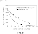
- FIG. 3 is a view illustrating a change in hydrogen sulfide concentration of a recovered concentrated ammonia liquor when a regenerated catalyst and a new catalyst of the present disclosure are used, from which it may be confirmed that the catalyst may be used semipermanently by regenerating the catalyst.
- the present disclosure which targets concentrated ammonia liquor used in an H 2 S scrubber (H 2 S/S) in a process of treating COG generated in a coke oven, relates to a method for reducing a concentration of the concentrated ammonia liquor by removing hydrogen sulfide (H 2 S) and hydrogen cyanide (HCN) dissolved in the concentrated ammonia liquor.
- concentrated ammonia liquor refers to an absorbent solution supplied to the H 2 S scrubber (H 2 S/S) to absorb hydrogen sulfide and hydrogen cyanide contained in the COG, and generally, it is an aqueous solution including NH 3 , H 2 S, CO 2 , HCN, and BTX (i.e., benzene, toluene and xylene), and has a pH of 9.5 to 10.5.
- H 2 S scrubber H 2 S/S
- BTX i.e., benzene, toluene and xylene
- the method therefor includes a catalyst treatment step of bringing concentrated ammonia liquor containing hydrogen sulfide (H 2 S) and hydrogen cyanide (HCN) into contact with an iron oxide catalyst; and a regeneration step of regenerating the iron oxide catalyst by supplying a regeneration liquid to the iron oxide catalyst.
- H 2 S hydrogen sulfide
- HN hydrogen cyanide
- the concentrated ammonia liquor used for purification of the COG is used to absorb hydrogen sulfide and hydrogen cyanide contained in the COG.
- absorption efficiency of hydrogen sulfide and hydrogen cyanide from the COG may be improved using the concentrated ammonia liquor of which the concentration is reduced by removing hydrogen sulfide and hydrogen cyanide, in the H 2 S scrubber (H 2 S/S).
- Hydrogen sulfide and hydrogen cyanide may be removed from the concentrated ammonia liquor through the catalyst treatment step of brining the concentrated ammonia liquor in contact with the iron oxide catalyst.
- Iron oxide that may be used at this time may be selected from the group consisting of iron oxide (FeO), triiron tetraoxide (Fe 3 O 4 ), hematite (Fe 2 O 3 ) and iron hydroxide (Fe(OH) 2 , Fe(OH) 3 ), and, preferably, the hematite (Fe 2 O 3 ) and the iron hydroxide (Fe(OH) 3 ) may be used.
- the contact step is not particularly limited, but may be performed by, for example, spraying the concentrated ammonia liquor to an iron oxide catalyst or immersing the iron oxide catalyst in the concentrated ammonia liquor, but a contact method thereof is not particularly limited.
- a contact method thereof is not particularly limited.
- the concentrated ammonia liquor and the iron oxide catalysts may be effectively brought into contact with each other, thereby increasing the efficiency of removing hydrogen sulfide and hydrogen cyanide from the concentrated ammonia liquor.
- a particulate phase may be used as the iron oxide catalyst.
- the particulate phase other than powder may be used to separate the solid sulfur in the regeneration step and easily regenerate the catalyst.
- Particles with an average particle diameter of, preferably, 2 to 10mm may be used, and particles with an average particle diameter of, most preferably, 3 to 8mm may be used, but the particles are not limited thereto and may be used without limitation as long as they have a size that may be easily separated from the solid sulfur in the regeneration step and be easy to regenerate the catalyst.
- the catalyst treatment step may be performed by supplying air, oxygen, or combinations thereof to the iron oxide catalyst.
- the air, oxygen, or combinations thereof may be supplied to the iron oxide catalyst in the same direction as a flow direction of the concentrated ammonia liquor when the concentrated ammonia liquor and the iron oxide catalyst come into contact with each other, and an activity of the iron oxide catalyst may be restored when the activity thereof is reduced by removing hydrogen sulfide and hydrogen cyanide contained in the concentrated ammonia liquor.
- air when the concentrated ammonia liquor is sprayed on the iron oxide catalyst, air may be supplied in the same direction as an injection direction of the concentrated ammonia liquor, and in this case, oxygen in the air may restore the activity of the iron oxide catalyst, and may be supplied in an appropriate amount depending on an amount of concentrated ammonia liquor to be treated, the concentrations of hydrogen sulfide and hydrogen cyanide contained in the concentrated ammonia liquor.
- the solid sulfur of S 2 to S 8 produced when hydrogen sulfide (H 2 S) comes into contact with the iron oxide catalyst and reacts therewith serves to remove hydrogen cyanide (HCN) by reacting with the hydrogen cyanide (HCN).
- HCN hydrogen cyanide
- the iron oxide catalyst is used in an amount of, preferably, 10 to 30g based on 1 L of the concentrated ammonia liquor, and in an amount of, more preferably, 15 to 25g.
- a weight of the iron oxide catalyst is less than 10g, the removal efficiency may be reduced due to an insufficient effect of the catalyst, and when the weight thereof exceeds 30g, an additional increase effect of the removal efficiency may be insignificant, which may be uneconomical.
- the concentration of hydrogen sulfide contained in the concentrated ammonia liquor may be reduced to 80% to 90% and the concentration of hydrogen cyanide may be reduced to 60% to 70% through the catalyst treatment step of bringing the concentrated ammonia liquor into contact with the iron oxide catalyst.
- the present disclosure includes a regeneration step in which the concentrated ammonia liquor is brought into contact with the iron oxide catalyst and then a catalyst is regenerated by supplying a regeneration liquid to the iron oxide catalyst.
- the regeneration step may be performed using an oxidative regeneration liquid, and in this case, the following reaction may occur.
- the regeneration liquid may serve to wash away solid sulfur generated on a catalyst surface.
- the regeneration liquid may be at least one oxidation regeneration liquid selected from the group consisting of water, ozone water, chlorine dioxide water, H 2 O 2 , NaOCl, NaClO 2 , NaClO 3 , NaClO 4 , KMnO 4 , and HNO 3 .
- At least one oxidizing gas selected from the group consisting of air, oxygen, ozone, and ClO 2 gases may be supplied to the iron oxide catalyst together with the regeneration liquid, and preferably, oxygen may be supplied.
- the oxidizing gas is supplied to the iron oxide catalyst together with the regeneration liquid to separate small particles such as solid sulfur from the iron oxide catalyst.
- a catalyst regenerated through the regeneration step may have a catalytic efficiency of 80% or more, as compared to a new catalyst.
- a regenerated catalyst may be regenerated so that the regenerated catalyst has a catalytic efficiency of 80% to 90%, as compared to the new catalyst.
- the iron oxide catalyst may be used semipermanently through the regeneration step, thereby reducing costs.
- a recovery step of recovering concentrated ammonia liquor obtained from the catalyst treatment step may be further included.
- the recovery step may include a solid-liquid separation process, and for example, in the recovery step, only the concentrated ammonia liquor may be recovered through solid-liquid separation by a decanting process by a specific gravity difference or centrifugation in order to additionally remove solid sulfur particles, but the present disclosure is not limited thereto.
- Example 2 After regenerating a catalyst while using distilled water as a regeneration liquid and injecting air, in order to compare the catalytic efficiency of the regenerated catalyst and a new catalyst, the same method as that of Example 1 was performed except for using the regenerated catalyst or the new catalyst, and then, the concentration change of hydrogen sulfide contained in the concentrated ammonia liquor was measured over time and results thereof is illustrated in FIG. 3 .
- the concentration of hydrogen sulfide decreased from 889 mg/L to 30 mg/L for the new catalyst, and the concentration of hydrogen sulfide decreased from 953 mg/L to 160 mg/L for the regenerated catalyst. Accordingly, the efficiency of removing hydrogen sulfide from the new catalyst was measured to be about 96.6%, and the efficiency of removing the regenerated catalyst was measured to be about 83.2%. Since the regenerated catalyst shows a hydrogen sulfide removal efficiency of 86.1% as compared to the new catalyst, it was confirmed that the catalyst may be used semipermanently by regenerating the catalyst.
Landscapes
- Chemical & Material Sciences (AREA)
- Engineering & Computer Science (AREA)
- Combustion & Propulsion (AREA)
- Organic Chemistry (AREA)
- Chemical Kinetics & Catalysis (AREA)
- Oil, Petroleum & Natural Gas (AREA)
- General Chemical & Material Sciences (AREA)
- Environmental & Geological Engineering (AREA)
- Health & Medical Sciences (AREA)
- Public Health (AREA)
- Toxicology (AREA)
- Materials Engineering (AREA)
- Life Sciences & Earth Sciences (AREA)
- Hydrology & Water Resources (AREA)
- Water Supply & Treatment (AREA)
- Analytical Chemistry (AREA)
- Inorganic Chemistry (AREA)
- Catalysts (AREA)
- Treatment Of Water By Oxidation Or Reduction (AREA)
Abstract
Description
- The present disclosure relates to a method for removing hydrogen sulfide (H2S) and hydrogen cyanide (HCN) contained in concentrated ammonia liquor used in an H2S scrubber (H2S/S) in a chemical by-product plant purifying coke oven gas (COG), and in particular, to a method for removing hydrogen sulfide (H2S) and hydrogen cyanide (HCN) contained in concentrated ammonia liquor using an iron oxide catalyst.
- A coke oven with multiple carbonization chambers charges coal using a charging car and then heats the coal at a temperature of approximately 1240°C or higher while blocking external air for about 19 hours, and produces gray-white coke from which volatile components contained in the coal are removed, which is a kind of coal-drying operation. Furthermore, coke that has been retorted is discharged from the carbonization chamber using an extruder, and is transported to a fire quenching tower and quenched.
- Meanwhile, although not illustrated in separate drawings, the COG described above is generated by thermal decomposition during a retorting process of the coal charged in the carbonization chamber, and the COG is transported to a purification facility (e.g., a chemical by-product plant) through a lifting tube provided at an upper portion of each carbonization chamber.
- The COG contains acidic gases such as hydrogen sulfide (H2S) and hydrogen cyanide (HCN), and when the COG is burned, hydrogen sulfide (H2S) is converted into sulfur dioxide (SO2), and hydrogen cyanide (HCN) is converted into nitrogen oxide (NOx), which may cause ultrafine dust. Thus, before the COG transported to the chemical by-product plant is burned, tar, hydrogen sulfide, and hydrogen cyanide need to be removed through a purification process. However, as environmental regulations are increasingly strengthened, quality improvement of COG is desired. Accordingly, as a method for improving the absorption efficiency of an H2S scrubber that removes hydrogen sulfide and hydrogen cyanide of the COG in the chemical by-product plant, a method for additionally installing the H2S scrubber and using sodium hydroxide (NaOH) compounds, ammonia (NH3) compounds, or amine compounds is used.
- Furthermore,
Korean Patent No. 10-0467774 - Accordingly, a method for removing hydrogen sulfide (H2S) and hydrogen cyanide (HCN) contained in concentrated ammonia liquor which is an absorption liquid supplied to an H2S scrubber in a relatively simple process may be expected to be useful in related fields.
- An aspect of the present disclosure is to provide a method for removing hydrogen sulfide (H2S) and hydrogen cyanide (HCN) contained in concentrated ammonia liquor using an iron oxide catalyst.
- According to an aspect of the present disclosure, a method for removing hydrogen sulfide (H2S) and hydrogen cyanide (HCN) contained in concentrated ammonia liquor includes: a catalyst treatment step of bringing concentrated ammonia liquor containing hydrogen sulfide (H2S) and hydrogen cyanide (HCN) into contact with an iron oxide catalyst; and a regeneration step of regenerating the iron oxide catalyst by supplying a regeneration liquid to the iron oxide catalyst.
- According to an aspect of the present disclosure, by simultaneously removing hydrogen sulfide (H2S) and hydrogen cyanide (HCN) contained in concentrated ammonia liquor, the absorption efficiency of hydrogen sulfide (H2S) and hydrogen cyanide (HCN) of coke oven gas (COG) may be improved when the concentrated ammonia liquor is used in an H2S scrubber (H2S/S).
-
FIG. 1 is a brief schematic diagram illustrating an exemplary treatment device configured to perform a method for removing hydrogen sulfide (H2S) and hydrogen cyanide (HCN) from the concentrated ammonia liquor of the present disclosure. -
FIG. 2 is a view illustrating concentrations of hydrogen sulfide and hydrogen cyanide contained in concentrated ammonia liquor before and after removing hydrogen sulfide and hydrogen cyanide from the concentrated ammonia liquor using an iron oxide catalyst of the present disclosure. -
FIG. 3 is a view illustrating a change in hydrogen sulfide concentration of a recovered concentrated ammonia liquor when a regenerated catalyst and a new catalyst of the present disclosure are used, from which it may be confirmed that the catalyst may be used semipermanently by regenerating the catalyst. - Hereinafter, a preferred embodiment of the present disclosure will be described. However, embodiments of the present disclosure may be modified in several different forms, and the scope of the present disclosure is not limited to the embodiments described below.
- The present disclosure which targets concentrated ammonia liquor used in an H2S scrubber (H2S/S) in a process of treating COG generated in a coke oven, relates to a method for reducing a concentration of the concentrated ammonia liquor by removing hydrogen sulfide (H2S) and hydrogen cyanide (HCN) dissolved in the concentrated ammonia liquor. In the present disclosure, concentrated ammonia liquor refers to an absorbent solution supplied to the H2S scrubber (H2S/S) to absorb hydrogen sulfide and hydrogen cyanide contained in the COG, and generally, it is an aqueous solution including NH3, H2S, CO2, HCN, and BTX (i.e., benzene, toluene and xylene), and has a pH of 9.5 to 10.5.
- More specifically, the method therefor includes a catalyst treatment step of bringing concentrated ammonia liquor containing hydrogen sulfide (H2S) and hydrogen cyanide (HCN) into contact with an iron oxide catalyst; and a regeneration step of regenerating the iron oxide catalyst by supplying a regeneration liquid to the iron oxide catalyst.
- The concentrated ammonia liquor used for purification of the COG is used to absorb hydrogen sulfide and hydrogen cyanide contained in the COG. Thus, absorption efficiency of hydrogen sulfide and hydrogen cyanide from the COG may be improved using the concentrated ammonia liquor of which the concentration is reduced by removing hydrogen sulfide and hydrogen cyanide, in the H2S scrubber (H2S/S).
- Hydrogen sulfide and hydrogen cyanide may be removed from the concentrated ammonia liquor through the catalyst treatment step of brining the concentrated ammonia liquor in contact with the iron oxide catalyst. Iron oxide that may be used at this time may be selected from the group consisting of iron oxide (FeO), triiron tetraoxide (Fe3O4), hematite (Fe2O3) and iron hydroxide (Fe(OH)2, Fe(OH)3), and, preferably, the hematite (Fe2O3) and the iron hydroxide (Fe(OH)3) may be used.
- The contact step is not particularly limited, but may be performed by, for example, spraying the concentrated ammonia liquor to an iron oxide catalyst or immersing the iron oxide catalyst in the concentrated ammonia liquor, but a contact method thereof is not particularly limited. For example, when the concentrated ammonia liquor is sprayed, the concentrated ammonia liquor and the iron oxide catalysts may be effectively brought into contact with each other, thereby increasing the efficiency of removing hydrogen sulfide and hydrogen cyanide from the concentrated ammonia liquor.
- A particulate phase may be used as the iron oxide catalyst. Specifically, since the catalyst may be mixed with solid sulfur generated in the catalyst treatment step, the particulate phase other than powder may be used to separate the solid sulfur in the regeneration step and easily regenerate the catalyst. Particles with an average particle diameter of, preferably, 2 to 10mm may be used, and particles with an average particle diameter of, most preferably, 3 to 8mm may be used, but the particles are not limited thereto and may be used without limitation as long as they have a size that may be easily separated from the solid sulfur in the regeneration step and be easy to regenerate the catalyst.
- Meanwhile, the catalyst treatment step may be performed by supplying air, oxygen, or combinations thereof to the iron oxide catalyst. The air, oxygen, or combinations thereof may be supplied to the iron oxide catalyst in the same direction as a flow direction of the concentrated ammonia liquor when the concentrated ammonia liquor and the iron oxide catalyst come into contact with each other, and an activity of the iron oxide catalyst may be restored when the activity thereof is reduced by removing hydrogen sulfide and hydrogen cyanide contained in the concentrated ammonia liquor. For example, when the concentrated ammonia liquor is sprayed on the iron oxide catalyst, air may be supplied in the same direction as an injection direction of the concentrated ammonia liquor, and in this case, oxygen in the air may restore the activity of the iron oxide catalyst, and may be supplied in an appropriate amount depending on an amount of concentrated ammonia liquor to be treated, the concentrations of hydrogen sulfide and hydrogen cyanide contained in the concentrated ammonia liquor.
- For example, when the air, oxygen, or combinations thereof is supplied to the iron oxide catalyst with a regeneration liquid during the catalyst treatment step, the following reaction occurs.
3H2S + Fe2O3 → Fe2S3 + 3H2O
3H2S + 2Fe(OH)3 → Fe2S3 + 6H2O
2Fe2S3 + 3O2 → 2Fe2O3 + 3S2
S2 + CN- → 2SCN-
SCN- + 2O2 + 2H2O → SO4 2- + CO2 + NH4 +
4S2 → S8
- That is, the solid sulfur of S2 to S8 produced when hydrogen sulfide (H2S) comes into contact with the iron oxide catalyst and reacts therewith serves to remove hydrogen cyanide (HCN) by reacting with the hydrogen cyanide (HCN). Thus, hydrogen sulfide and hydrogen cyanide may be removed together.
- Then, carbon dioxide generated during the reaction process is released in the form of a gas, and ammonium ions and sulfate ions are present as ions in the concentrated ammonia liquor.
- The iron oxide catalyst is used in an amount of, preferably, 10 to 30g based on 1 L of the concentrated ammonia liquor, and in an amount of, more preferably, 15 to 25g. When a weight of the iron oxide catalyst is less than 10g, the removal efficiency may be reduced due to an insufficient effect of the catalyst, and when the weight thereof exceeds 30g, an additional increase effect of the removal efficiency may be insignificant, which may be uneconomical.
- In the present disclosure, the concentration of hydrogen sulfide contained in the concentrated ammonia liquor may be reduced to 80% to 90% and the concentration of hydrogen cyanide may be reduced to 60% to 70% through the catalyst treatment step of bringing the concentrated ammonia liquor into contact with the iron oxide catalyst.
- Meanwhile, the present disclosure includes a regeneration step in which the concentrated ammonia liquor is brought into contact with the iron oxide catalyst and then a catalyst is regenerated by supplying a regeneration liquid to the iron oxide catalyst.
- The regeneration step may be performed using an oxidative regeneration liquid, and in this case, the following reaction may occur.
2Fe2S3 + 6H2O2 → 2Fe2O3 + 6H2O + 3S2
2Fe2S3 + 6H2O2 → 4Fe (OH) 3 + 3S2
2Fe2S3 + 6ClO- → 2Fe2O3 + 6Cl- + 3S2
2Fe2S3 + 3ClO2 - → 2Fe2O3 + 3Cl- + 3S2
- Furthermore, the regeneration liquid may serve to wash away solid sulfur generated on a catalyst surface.
- The regeneration liquid may be at least one oxidation regeneration liquid selected from the group consisting of water, ozone water, chlorine dioxide water, H2O2, NaOCl, NaClO2, NaClO3, NaClO4, KMnO4, and HNO3.
- In the regeneration step, at least one oxidizing gas selected from the group consisting of air, oxygen, ozone, and ClO2 gases may be supplied to the iron oxide catalyst together with the regeneration liquid, and preferably, oxygen may be supplied.
2Fe2S3 + 3O2 → 2Fe2O3 + 3S2
2Fe2S3 + 3O2 + 6H2O → 4Fe (OH) 3 + 3S2
- As in the reaction described above, the oxidizing gas is supplied to the iron oxide catalyst together with the regeneration liquid to separate small particles such as solid sulfur from the iron oxide catalyst.
- A catalyst regenerated through the regeneration step may have a catalytic efficiency of 80% or more, as compared to a new catalyst. In consideration of the time and costs required for the catalyst regeneration step, a regenerated catalyst may be regenerated so that the regenerated catalyst has a catalytic efficiency of 80% to 90%, as compared to the new catalyst. The iron oxide catalyst may be used semipermanently through the regeneration step, thereby reducing costs.
- In the present disclosure, a recovery step of recovering concentrated ammonia liquor obtained from the catalyst treatment step may be further included.
- The recovery step may include a solid-liquid separation process, and for example, in the recovery step, only the concentrated ammonia liquor may be recovered through solid-liquid separation by a decanting process by a specific gravity difference or centrifugation in order to additionally remove solid sulfur particles, but the present disclosure is not limited thereto.
- Hereinafter, the present disclosure will be described in more detail with reference to specific embodiments. The following embodiments are merely examples for better understanding of the present disclosure, and the scope of the present disclosure is not limited thereto.
- 1L of concentrated ammonia liquor at room temperature (25°C) in which 953 mg/L of hydrogen sulfide (H2S) and 524 mg/L of hydrogen cyanide (HCN) were dissolved was sprayed and injected into a reactor filled with 20g of particulate hematite (Fe2O3) catalyst having an average particle diameter of 4 mm. At the same time, air was circulated inside the catalytic reactor. Afterwards, the concentrated ammonia liquor that passed through the iron oxide catalyst was recovered, and the concentration of hydrogen sulfide contained in the recovered concentrated ammonia liquor was calculated by ion chromatography, and the concentration of hydrogen cyanide was analyzed by a continuous flow method, and the results thereof are illustrated in
FIG. 2 . - As illustrated in
FIG. 2 , hydrogen sulfide contained in the concentrated ammonia liquor was reduced to 160 mg/L, and hydrogen cyanide contained therein was reduced to 200 mg/L. - After regenerating a catalyst while using distilled water as a regeneration liquid and injecting air, in order to compare the catalytic efficiency of the regenerated catalyst and a new catalyst, the same method as that of Example 1 was performed except for using the regenerated catalyst or the new catalyst, and then, the concentration change of hydrogen sulfide contained in the concentrated ammonia liquor was measured over time and results thereof is illustrated in
FIG. 3 . - As illustrated in
FIG. 3 , when the regenerated catalyst and the new catalyst react for the same time, after 120 minutes, the concentration of hydrogen sulfide decreased from 889 mg/L to 30 mg/L for the new catalyst, and the concentration of hydrogen sulfide decreased from 953 mg/L to 160 mg/L for the regenerated catalyst. Accordingly, the efficiency of removing hydrogen sulfide from the new catalyst was measured to be about 96.6%, and the efficiency of removing the regenerated catalyst was measured to be about 83.2%. Since the regenerated catalyst shows a hydrogen sulfide removal efficiency of 86.1% as compared to the new catalyst, it was confirmed that the catalyst may be used semipermanently by regenerating the catalyst. - While exemplary embodiments have been described and described above, the scope of the present disclosure is not limited thereto. It will be apparent to those skilled in the art that modifications and variations could be made without departing from the scope of the present disclosure as defined by the appended claims.
-
- 10, 40: Oxygen storage tank
- 12: Concentrated Ammonia Liquor Reservoir Before Treatment
- 14, 20: Solenoid valve for Concentrated Ammonia Liquor
- 16, 26: Catalytic Reactor
- 18, 28: Iron Oxide Catalyst
- 22: Solid-Liquid Separator
- 24: Concentrated Ammonia Liquor Reservoir After Treatment
- 30, 32: Solenoid Valve for Supplying Air, Oxygen, Ozone or ClO2 Gases
- 42: Regeneration liquid Reservoir
- 44, 46: Solenoid Valve for Regeneration liquid
- 48, 50: Solenoid Valve for Supplying Air, Oxygen, Ozone or ClO2 Gases
Claims (7)
- A method for removing hydrogen sulfide (H2S) and hydrogen cyanide (HCN) from concentrated ammonia liquor, the method comprising:a catalyst treatment step of bringing concentrated ammonia liquor containing hydrogen sulfide (H2S) and hydrogen cyanide (HCN) into contact with an iron oxide catalyst; anda regeneration step of regenerating the iron oxide catalyst by supplying a regeneration liquid to the iron oxide catalyst.
- The method for removing hydrogen sulfide (H2S) and hydrogen cyanide (HCN) from concentrated ammonia liquor of claim 1, wherein the iron oxide catalyst is particulate.
- The method for removing hydrogen sulfide (H2S) and hydrogen cyanide (HCN) from concentrated ammonia liquor of claim 1, wherein the regeneration liquid is at least one oxidation regeneration liquid selected from the group consisting of water, ozone water, chlorine dioxide water, H2O2, NaOCl, NaClO2, NaClO3, NaClO4, KMnO4, and HNO3.
- The method for removing hydrogen sulfide (H2S) and hydrogen cyanide (HCN) from concentrated ammonia liquor of claim 1, wherein the catalyst treatment step is performed by supplying air, oxygen, or combinations thereof together.
- The method for removing hydrogen sulfide (H2S) and hydrogen cyanide (HCN) from concentrated ammonia liquor of claim 1, wherein the regeneration step is performed along with at least one oxidation gas selected from the group consisting of air, oxygen, ozone, and ClO2 gases.
- The method for removing hydrogen sulfide (H2S) and hydrogen cyanide (HCN) from concentrated ammonia liquor of one of claims 1 to 5, further comprising:
a recovery step of recovering the concentrated ammonia liquor obtained from the catalyst treatment step. - The method for removing hydrogen sulfide (H2S) and hydrogen cyanide (HCN) from concentrated ammonia liquor of claim 6, wherein the recovery step includes a solid-liquid separation process.
Applications Claiming Priority (2)
| Application Number | Priority Date | Filing Date | Title |
|---|---|---|---|
| KR1020200175192A KR102482248B1 (en) | 2020-12-15 | 2020-12-15 | Method for removing h2s and hcn species contained in deacidified water |
| PCT/KR2021/019042 WO2022131778A1 (en) | 2020-12-15 | 2021-12-15 | Method for simultaneously removing hydrogen sulfide (h2s) and hydrogen cyanide (hcn) from concentrated ammonia liquor |
Publications (3)
| Publication Number | Publication Date |
|---|---|
| EP4265706A1 true EP4265706A1 (en) | 2023-10-25 |
| EP4265706A4 EP4265706A4 (en) | 2024-06-12 |
| EP4265706B1 EP4265706B1 (en) | 2025-06-11 |
Family
ID=82057929
Family Applications (1)
| Application Number | Title | Priority Date | Filing Date |
|---|---|---|---|
| EP21907082.8A Active EP4265706B1 (en) | 2020-12-15 | 2021-12-15 | Method for simultaneously removing hydrogen sulfide (h2s) and hydrogen cyanide (hcn) from concentrated ammonia liquor |
Country Status (4)
| Country | Link |
|---|---|
| EP (1) | EP4265706B1 (en) |
| KR (1) | KR102482248B1 (en) |
| CN (1) | CN116583581B (en) |
| WO (1) | WO2022131778A1 (en) |
Family Cites Families (16)
| Publication number | Priority date | Publication date | Assignee | Title |
|---|---|---|---|---|
| US3956460A (en) * | 1973-11-05 | 1976-05-11 | Ralph M. Parsons Company | Process for the treatment of gas streams containing hydrogen cyanide |
| US4435371A (en) * | 1982-02-26 | 1984-03-06 | The Goodyear Tire & Rubber Company | Sulfur removal from a gas stream |
| JPS61268792A (en) * | 1985-05-22 | 1986-11-28 | Kawasaki Steel Corp | Method of purifying industrial gas |
| JPS63200816A (en) * | 1987-02-18 | 1988-08-19 | Nkk Corp | Gas desulfurization control method |
| JP4187845B2 (en) * | 1998-11-10 | 2008-11-26 | 大阪瓦斯株式会社 | Method for treating ammonia-containing water |
| JP2000248286A (en) * | 1999-03-02 | 2000-09-12 | Jgc Corp | Purification process for coke oven gas |
| KR100467774B1 (en) | 2000-12-22 | 2005-01-24 | 주식회사 포스코 | A method for inhibiting fixed ammonia production in ammoniacal liquor |
| KR100510831B1 (en) * | 2001-12-22 | 2005-08-30 | 주식회사 포스코 | A Treatment Method For Ammonia Liquor And A Purification Method of COG By Using The Treated Ammonia Liquor |
| US7396522B2 (en) | 2003-12-05 | 2008-07-08 | Jayalekshmy Ayyer | Catalyst useful for removal of hydrogen sulphide from gas stream and its conversion to sulphur, a process for preparing such catalyst and a method for removing of hydrogen sulphide using said catalyst |
| JP5147233B2 (en) * | 2006-12-27 | 2013-02-20 | 川崎エンジニアリング株式会社 | Gas desulfurization method and desulfurization equipment |
| KR100961394B1 (en) * | 2007-12-21 | 2010-06-07 | 주식회사 포스코 | Method for preparing zinc ferrite catalyst for removing hydrogen sulfide contained in coke oven gas |
| CN101284205A (en) * | 2008-06-06 | 2008-10-15 | 昆明理工大学 | Purification and recovery method of hydrogen cyanide in a kind of industrial waste gas |
| KR101118538B1 (en) * | 2009-08-26 | 2012-02-24 | 재단법인 포항산업과학연구원 | Method for removing hydrogen sulfide by using ferrous compound |
| JP5637797B2 (en) * | 2010-10-05 | 2014-12-10 | 千代田化工建設株式会社 | Method and apparatus for treating wastewater containing persistent materials |
| KR20130076596A (en) * | 2011-12-28 | 2013-07-08 | 재단법인 포항산업과학연구원 | Method for simultaneous removal of co2, h2s and hcn using ammonia |
| KR101403805B1 (en) * | 2012-09-04 | 2014-06-11 | 재단법인 포항산업과학연구원 | Catalyst for removing acidic gas contained in coke oven gas and method for producing the same |
-
2020
- 2020-12-15 KR KR1020200175192A patent/KR102482248B1/en active Active
-
2021
- 2021-12-15 EP EP21907082.8A patent/EP4265706B1/en active Active
- 2021-12-15 WO PCT/KR2021/019042 patent/WO2022131778A1/en not_active Ceased
- 2021-12-15 CN CN202180084248.9A patent/CN116583581B/en active Active
Also Published As
| Publication number | Publication date |
|---|---|
| CN116583581B (en) | 2026-04-28 |
| KR20220085267A (en) | 2022-06-22 |
| EP4265706B1 (en) | 2025-06-11 |
| WO2022131778A1 (en) | 2022-06-23 |
| CN116583581A (en) | 2023-08-11 |
| KR102482248B1 (en) | 2022-12-28 |
| EP4265706A4 (en) | 2024-06-12 |
Similar Documents
| Publication | Publication Date | Title |
|---|---|---|
| US4466828A (en) | Process for smelting nickel | |
| US8496895B2 (en) | Exhaust gas treating apparatus and treating method for carbon dioxide capture process | |
| US4163043A (en) | Process for removing H2 S and CO2 from gases and regenerating the adsorbing solution | |
| KR101839225B1 (en) | Method for purification of coke oven gas and device for purification of coke oven gas | |
| EP0091392B2 (en) | Sulfur removal from a gas stream | |
| KR100811500B1 (en) | How to recover and recycle ammonia from the reactor effluent stream | |
| CN109173669B (en) | Method for purifying yellow phosphorus tail gas | |
| CN1045191C (en) | A method of regenerating cyanide from thiocyanate | |
| CN100571849C (en) | A kind of treatment process of discharged doctor solution of HPF desulfurization system of coke-oven plant | |
| EP4265706B1 (en) | Method for simultaneously removing hydrogen sulfide (h2s) and hydrogen cyanide (hcn) from concentrated ammonia liquor | |
| US3953577A (en) | Process for purifying gases containing HCN | |
| US4013779A (en) | Process for removal of ammonia, hydrogen sulfide and hydrogen cyanide from gases containing these substances | |
| CN106606924A (en) | Desulphurization method and apparatus for sulfur-containing tail gas from rotary volatilizing kiln | |
| JP2000153284A (en) | Ozone cyan treatment method | |
| US5215728A (en) | Method and apparatus for removal of h2s from a process gas, including thiosulfate and/or cyanide salt decomposition | |
| KR101172125B1 (en) | Method for removing of nitrogen oxides | |
| CN108970353B (en) | Comprehensive desulfurization and denitrification method for catalytic flue gas and ammonia-containing acid gas | |
| CN112742376B (en) | Supported Fenton oxidation catalyst | |
| KR100405522B1 (en) | How to exclude carbon dioxide capture in coke gas purification | |
| US5695727A (en) | Process for removing sulfur dioxide and nitrogen oxides from a hot gaseous stream with ferrous chelate regeneration | |
| JP4266267B2 (en) | Exhaust gas treatment method and apparatus | |
| KR20120074844A (en) | Method for removal of hydrogen sulfide by catalysts | |
| CN114891542A (en) | Treatment method of coke oven gas desulfurization waste liquid | |
| JPH06262038A (en) | Method for treatment of exhaust gas | |
| WO1998015340A1 (en) | Exhaust gas processing method |
Legal Events
| Date | Code | Title | Description |
|---|---|---|---|
| STAA | Information on the status of an ep patent application or granted ep patent |
Free format text: STATUS: THE INTERNATIONAL PUBLICATION HAS BEEN MADE |
|
| PUAI | Public reference made under article 153(3) epc to a published international application that has entered the european phase |
Free format text: ORIGINAL CODE: 0009012 |
|
| STAA | Information on the status of an ep patent application or granted ep patent |
Free format text: STATUS: REQUEST FOR EXAMINATION WAS MADE |
|
| 17P | Request for examination filed |
Effective date: 20230705 |
|
| AK | Designated contracting states |
Kind code of ref document: A1 Designated state(s): AL AT BE BG CH CY CZ DE DK EE ES FI FR GB GR HR HU IE IS IT LI LT LU LV MC MK MT NL NO PL PT RO RS SE SI SK SM TR |
|
| DAV | Request for validation of the european patent (deleted) | ||
| DAX | Request for extension of the european patent (deleted) | ||
| A4 | Supplementary search report drawn up and despatched |
Effective date: 20240514 |
|
| RIC1 | Information provided on ipc code assigned before grant |
Ipc: C01C 1/02 20060101ALI20240508BHEP Ipc: C02F 1/72 20060101ALI20240508BHEP Ipc: C10B 33/00 20060101ALI20240508BHEP Ipc: C10K 1/08 20060101ALI20240508BHEP Ipc: C10K 1/00 20060101AFI20240508BHEP |
|
| GRAP | Despatch of communication of intention to grant a patent |
Free format text: ORIGINAL CODE: EPIDOSNIGR1 |
|
| STAA | Information on the status of an ep patent application or granted ep patent |
Free format text: STATUS: GRANT OF PATENT IS INTENDED |
|
| INTG | Intention to grant announced |
Effective date: 20250220 |
|
| GRAS | Grant fee paid |
Free format text: ORIGINAL CODE: EPIDOSNIGR3 |
|
| GRAA | (expected) grant |
Free format text: ORIGINAL CODE: 0009210 |
|
| STAA | Information on the status of an ep patent application or granted ep patent |
Free format text: STATUS: THE PATENT HAS BEEN GRANTED |
|
| AK | Designated contracting states |
Kind code of ref document: B1 Designated state(s): AL AT BE BG CH CY CZ DE DK EE ES FI FR GB GR HR HU IE IS IT LI LT LU LV MC MK MT NL NO PL PT RO RS SE SI SK SM TR |
|
| REG | Reference to a national code |
Ref country code: GB Ref legal event code: FG4D |
|
| REG | Reference to a national code |
Ref country code: CH Ref legal event code: EP |
|
| REG | Reference to a national code |
Ref country code: IE Ref legal event code: FG4D |
|
| REG | Reference to a national code |
Ref country code: DE Ref legal event code: R096 Ref document number: 602021032274 Country of ref document: DE |
|
| PG25 | Lapsed in a contracting state [announced via postgrant information from national office to epo] |
Ref country code: ES Free format text: LAPSE BECAUSE OF FAILURE TO SUBMIT A TRANSLATION OF THE DESCRIPTION OR TO PAY THE FEE WITHIN THE PRESCRIBED TIME-LIMIT Effective date: 20250611 Ref country code: FI Free format text: LAPSE BECAUSE OF FAILURE TO SUBMIT A TRANSLATION OF THE DESCRIPTION OR TO PAY THE FEE WITHIN THE PRESCRIBED TIME-LIMIT Effective date: 20250611 |
|
| REG | Reference to a national code |
Ref country code: LT Ref legal event code: MG9D |
|
| PG25 | Lapsed in a contracting state [announced via postgrant information from national office to epo] |
Ref country code: GR Free format text: LAPSE BECAUSE OF FAILURE TO SUBMIT A TRANSLATION OF THE DESCRIPTION OR TO PAY THE FEE WITHIN THE PRESCRIBED TIME-LIMIT Effective date: 20250912 Ref country code: NO Free format text: LAPSE BECAUSE OF FAILURE TO SUBMIT A TRANSLATION OF THE DESCRIPTION OR TO PAY THE FEE WITHIN THE PRESCRIBED TIME-LIMIT Effective date: 20250911 |
|
| REG | Reference to a national code |
Ref country code: NL Ref legal event code: MP Effective date: 20250611 |
|
| PG25 | Lapsed in a contracting state [announced via postgrant information from national office to epo] |
Ref country code: BG Free format text: LAPSE BECAUSE OF FAILURE TO SUBMIT A TRANSLATION OF THE DESCRIPTION OR TO PAY THE FEE WITHIN THE PRESCRIBED TIME-LIMIT Effective date: 20250611 |
|
| PG25 | Lapsed in a contracting state [announced via postgrant information from national office to epo] |
Ref country code: HR Free format text: LAPSE BECAUSE OF FAILURE TO SUBMIT A TRANSLATION OF THE DESCRIPTION OR TO PAY THE FEE WITHIN THE PRESCRIBED TIME-LIMIT Effective date: 20250611 |
|
| PG25 | Lapsed in a contracting state [announced via postgrant information from national office to epo] |
Ref country code: RS Free format text: LAPSE BECAUSE OF FAILURE TO SUBMIT A TRANSLATION OF THE DESCRIPTION OR TO PAY THE FEE WITHIN THE PRESCRIBED TIME-LIMIT Effective date: 20250911 |
|
| PG25 | Lapsed in a contracting state [announced via postgrant information from national office to epo] |
Ref country code: LV Free format text: LAPSE BECAUSE OF FAILURE TO SUBMIT A TRANSLATION OF THE DESCRIPTION OR TO PAY THE FEE WITHIN THE PRESCRIBED TIME-LIMIT Effective date: 20250611 |
|
| PG25 | Lapsed in a contracting state [announced via postgrant information from national office to epo] |
Ref country code: NL Free format text: LAPSE BECAUSE OF FAILURE TO SUBMIT A TRANSLATION OF THE DESCRIPTION OR TO PAY THE FEE WITHIN THE PRESCRIBED TIME-LIMIT Effective date: 20250611 |
|
| PG25 | Lapsed in a contracting state [announced via postgrant information from national office to epo] |
Ref country code: PT Free format text: LAPSE BECAUSE OF FAILURE TO SUBMIT A TRANSLATION OF THE DESCRIPTION OR TO PAY THE FEE WITHIN THE PRESCRIBED TIME-LIMIT Effective date: 20251013 |
|
| REG | Reference to a national code |
Ref country code: AT Ref legal event code: MK05 Ref document number: 1802304 Country of ref document: AT Kind code of ref document: T Effective date: 20250611 |
|
| PG25 | Lapsed in a contracting state [announced via postgrant information from national office to epo] |
Ref country code: IS Free format text: LAPSE BECAUSE OF FAILURE TO SUBMIT A TRANSLATION OF THE DESCRIPTION OR TO PAY THE FEE WITHIN THE PRESCRIBED TIME-LIMIT Effective date: 20251011 |
|
| PG25 | Lapsed in a contracting state [announced via postgrant information from national office to epo] |
Ref country code: SM Free format text: LAPSE BECAUSE OF FAILURE TO SUBMIT A TRANSLATION OF THE DESCRIPTION OR TO PAY THE FEE WITHIN THE PRESCRIBED TIME-LIMIT Effective date: 20250611 Ref country code: AT Free format text: LAPSE BECAUSE OF FAILURE TO SUBMIT A TRANSLATION OF THE DESCRIPTION OR TO PAY THE FEE WITHIN THE PRESCRIBED TIME-LIMIT Effective date: 20250611 |
|
| PG25 | Lapsed in a contracting state [announced via postgrant information from national office to epo] |
Ref country code: CZ Free format text: LAPSE BECAUSE OF FAILURE TO SUBMIT A TRANSLATION OF THE DESCRIPTION OR TO PAY THE FEE WITHIN THE PRESCRIBED TIME-LIMIT Effective date: 20250611 |
|
| PG25 | Lapsed in a contracting state [announced via postgrant information from national office to epo] |
Ref country code: PL Free format text: LAPSE BECAUSE OF FAILURE TO SUBMIT A TRANSLATION OF THE DESCRIPTION OR TO PAY THE FEE WITHIN THE PRESCRIBED TIME-LIMIT Effective date: 20250611 |
|
| PG25 | Lapsed in a contracting state [announced via postgrant information from national office to epo] |
Ref country code: EE Free format text: LAPSE BECAUSE OF FAILURE TO SUBMIT A TRANSLATION OF THE DESCRIPTION OR TO PAY THE FEE WITHIN THE PRESCRIBED TIME-LIMIT Effective date: 20250611 |
|
| PG25 | Lapsed in a contracting state [announced via postgrant information from national office to epo] |
Ref country code: SK Free format text: LAPSE BECAUSE OF FAILURE TO SUBMIT A TRANSLATION OF THE DESCRIPTION OR TO PAY THE FEE WITHIN THE PRESCRIBED TIME-LIMIT Effective date: 20250611 |
|
| PG25 | Lapsed in a contracting state [announced via postgrant information from national office to epo] |
Ref country code: RO Free format text: LAPSE BECAUSE OF FAILURE TO SUBMIT A TRANSLATION OF THE DESCRIPTION OR TO PAY THE FEE WITHIN THE PRESCRIBED TIME-LIMIT Effective date: 20250611 |
|
| REG | Reference to a national code |
Ref country code: DE Ref legal event code: R097 Ref document number: 602021032274 Country of ref document: DE |
|
| PG25 | Lapsed in a contracting state [announced via postgrant information from national office to epo] |
Ref country code: DK Free format text: LAPSE BECAUSE OF FAILURE TO SUBMIT A TRANSLATION OF THE DESCRIPTION OR TO PAY THE FEE WITHIN THE PRESCRIBED TIME-LIMIT Effective date: 20250611 |
|
| PGFP | Annual fee paid to national office [announced via postgrant information from national office to epo] |
Ref country code: DE Payment date: 20251229 Year of fee payment: 5 |
|
| PG25 | Lapsed in a contracting state [announced via postgrant information from national office to epo] |
Ref country code: IT Free format text: LAPSE BECAUSE OF FAILURE TO SUBMIT A TRANSLATION OF THE DESCRIPTION OR TO PAY THE FEE WITHIN THE PRESCRIBED TIME-LIMIT Effective date: 20250611 |
|
| PLBE | No opposition filed within time limit |
Free format text: ORIGINAL CODE: 0009261 |
|
| STAA | Information on the status of an ep patent application or granted ep patent |
Free format text: STATUS: NO OPPOSITION FILED WITHIN TIME LIMIT |
|
| REG | Reference to a national code |
Ref country code: CH Ref legal event code: L10 Free format text: ST27 STATUS EVENT CODE: U-0-0-L10-L00 (AS PROVIDED BY THE NATIONAL OFFICE) Effective date: 20260423 |