EP4265556B1 - Antriebsmaschine für einen aufzug - Google Patents
Antriebsmaschine für einen aufzug Download PDFInfo
- Publication number
- EP4265556B1 EP4265556B1 EP23168005.9A EP23168005A EP4265556B1 EP 4265556 B1 EP4265556 B1 EP 4265556B1 EP 23168005 A EP23168005 A EP 23168005A EP 4265556 B1 EP4265556 B1 EP 4265556B1
- Authority
- EP
- European Patent Office
- Prior art keywords
- drive shaft
- electric motor
- drive
- rotor
- coupling
- Prior art date
- Legal status (The legal status is an assumption and is not a legal conclusion. Google has not performed a legal analysis and makes no representation as to the accuracy of the status listed.)
- Active
Links
Images

Classifications
-
- B—PERFORMING OPERATIONS; TRANSPORTING
- B66—HOISTING; LIFTING; HAULING
- B66B—ELEVATORS; ESCALATORS OR MOVING WALKWAYS
- B66B11/00—Main component parts of lifts in, or associated with, buildings or other structures
- B66B11/04—Driving gear ; Details thereof, e.g. seals
- B66B11/043—Driving gear ; Details thereof, e.g. seals actuated by rotating motor; Details, e.g. ventilation
Definitions
- the invention relates to a drive machine for an elevator, wherein the drive machine comprises an electric motor and a drive shaft, and wherein the drive shaft can be driven by means of the electric motor and is also mounted on both sides in respective bearings.
- the drive shaft can in particular be designed to drive at least one belt, for example a flat belt or a profile belt.
- the drive shaft can thus be designed in particular as a belt shaft.
- Such drive machines or drive arrangements are already used in the state of the art to move elevator cars in an elevator shaft, whereby the use of flat or profile belts as a suspension element has the significant advantage over classic round suspension cables that traction sheaves with a correspondingly large diameter (typically greater than 500 mm) are no longer required, but that the drive shaft can have a comparatively small diameter (typically less than 300 mm) due to the better traction between the drive shaft and the belt. This also reduces the requirements for the torque that the electric motor must provide to drive the drive shaft, so that the electric motor can be designed in particular without a gear.
- WO 2009/075670 A1 a drive machine for an elevator is disclosed with an electric motor and a traction sheave that can be driven and supported by the electric motor, and wherein a coupling is provided via which the electric motor can be mechanically coupled to the traction sheave so that the traction sheave rotates in response to a movement of the electric motor.
- the invention is based on the object of providing a drive machine that is powerful and safe and at the same time easy to transport and assemble.
- the features of claim 1 are provided according to the invention in a drive machine.
- a rotor of the electric motor is connected gearless and rotationally fixed to the drive shaft via a detachable coupling and that, furthermore, the electric motor is suspended freely in space on the drive shaft by means of the coupling.
- the drive shaft can preferably carry the electric motor.
- the drive shaft centers the rotation axis of the electric motor's rotor.
- a substructure supporting the electric motor such as complex pendulum feet or the like, over-determination is also avoided, so that no dangerous mechanical stresses can build up during operation.
- the electric motor or more precisely its housing, can have support feet for intermediate storage. However, once the electric motor has been mounted on the drive shaft, these support feet hang in the air.
- a significant advantage of such a design is that the electric motor, or more precisely its rotor, and the drive shaft can be easily dismantled and transported separately to the location where the drive machine is installed. This simplifies the transport of the drive machine.
- the drive shaft can be made much shorter than if it were designed as a single piece with the rotor of the electric motor. This also makes it easier to assemble the drive machine at the location of use.
- the coupling between the rotor and the drive shaft can be designed in such a way that either the rotor is inserted into the drive shaft or the drive shaft is inserted into the rotor.
- the electric motor can be plugged onto the drive shaft or inserted into the drive shaft or can be after assembly.
- the drive shaft can already be installed in a fixed position using a support structure, whereby the support structure carries the bearings that support the drive shaft.
- the drive shaft can thus be designed as a belt shaft and have several adjacent running surfaces (as traction surface for the respective belt), each of which is designed to drive a belt (which carries the respective elevator car as a support means).
- the easy dismantling of the electric motor due to the coupling is also an advantage because it enables independent testing of the two units of the drive machine connected to one another via the detachable coupling, namely on the one hand a supporting structure that carries the drive shaft (and absorbs holding loads) and on the other hand the electric motor that is freely suspended from the drive shaft.
- the electric motor can be designed free from a machine frame due to the freely suspended construction.
- the motor housing can therefore be the only structure that separates the electric motor from the outside.
- the free suspension has the advantage that the electric motor can be aligned with the drive shaft without stress. This prevents misalignment and thus a rocking load on the drive train of the drive machine, especially in the area of the clutch (during operation). In addition, there is no need for a complex substructure to which the electric motor has to be laboriously aligned and supported.
- the rotor can be mounted within the electric motor in a conventional manner by means of a bearing on the A (output side) and B side.
- the drive machine according to claim 1 can additionally be characterized in that at least one braking device for braking the drive shaft is arranged on the output side of the clutch, i.e. preferably between the bearings on both sides of the drive shaft.
- Such an arrangement of the at least one braking device has advantages in terms of the simple design of the drive machine, since safety is still ensured is ensured if the clutch provides a rotationally fixed connection between the rotor and the drive shaft only by means of frictional engagement. In the event of failure of this frictional engagement, the load carried by the drive machine via the belts can be held securely in position by holding the drive shaft, regardless of the position of the rotor of the electric motor, ie even if the clutch fails.
- the braking device can be designed as a caliper and/or disc brake.
- the respective braking device can also comprise several brake shoes.
- Claim 3 describes a further possible embodiment of a drive machine according to the invention:
- the drive machine according to claim 1 can also be characterized in that a coupling surface of the coupling is conical. Due to the conical shape, a frictional connection can be created in the area of the coupling surface, which creates the desired rotationally fixed connection between the drive shaft and the rotor.
- a frictional connection can preferably be achieved by tightening an outer cone, preferably by means of a screw connection, onto an inner cone.
- the outer cone can, for example, be formed by the drive shaft and the inner cone by the rotor. However, it is just as possible for the outer cone to be formed by the rotor and the inner cone to be formed by the drive shaft.
- the inner and outer cones can alternatively also be provided by respective separate elements of a clamping coupling, as will be explained in more detail below.
- the mentioned screw connection which tightens the outer cone onto the inner cone, can be achieved, for example, by means of at least one tightening screw which is directed in the direction of a axis of rotation of the drive shaft.
- This allows axial tightening forces to be generated which, due to the conical shape of the coupling surface, on the one hand produce the desired frictional connection and thus the rotationally fixed connection between the rotor and the drive shaft and, on the other hand, centre the rotor to the drive shaft.
- the axis of rotation of the rotor can coincide with the axis of rotation of the drive shaft.
- the at least one tightening screw can be supported on a respective shoulder or step which forms the element (rotor or drive shaft) which forms the inner cone and/or engage in a thread which is formed in the element (rotor or drive shaft) which forms the outer cone.
- a corresponding passage can be formed in the rotor through which the tightening screw is guided so that it can engage in a thread in the drive shaft and thus tighten the drive shaft (which in this case forms the outer cone) onto the rotor.
- the tightening screw can be guided through a passage in the drive shaft on the drive side in order to engage in a thread formed in the rotor.
- a tightening screw arranged centrally on the axis of rotation can be used; alternatively or additionally, tightening screws arranged collinearly to the axis of rotation can also be provided.
- a drive machine can thus be characterized in that the rotor is designed as a hollow shaft on one side of the drive shaft and as a solid shaft on an opposite side.
- this design has the advantage that comparatively small and therefore inexpensive, preferably optical, rotary encoders can be mounted on the solid shaft formed by the rotor (on the B side of the electric motor).
- the clutch is at least partially arranged within a housing of the electric motor.
- a clutch surface of the clutch can be arranged (at least partially, but preferably completely) within a housing of the electric motor. This clutch surface can thus transmit a drive torque of the electric motor to the drive shaft.
- the arrangement of the clutch at least partially within the housing of the electric motor has the advantage that a spacing between the housing of the electric motor and a supporting structure that carries the bearings of the drive shaft only has to be designed as an assembly gap so large that a tool (e.g. torque wrench) for assembling or disassembling the coupling connection provided by the clutch fits into it.
- the coupling provides or creates a rotationally fixed connection between the drive shaft and the rotor by means of frictional engagement and/or without form-fitting.
- the coupling preferably has no elastic elements so that the coupling can transmit a drive torque of the electric motor to the drive shaft without play.
- the coupling has a clamping element and a counter-clamping element, i.e. the coupling can be designed as a clamping coupling.
- the clamping element and the counter-clamping element can be clamped or clamped axially against each other, whereby this clamping can preferably be achieved by means of a screw connection.
- the clamping element can also form an inner cone on which an outer cone of the counter-clamping element rests (in the assembled state).
- the coupling can thus be designed in particular as a ring clamping element.
- the clamping element and the counter-clamping element can thus be designed separately from the drive shaft and the rotor.
- Such separate clamping and counter-clamping elements can also form a conical coupling surface as described above and this can also be arranged (at least partially but preferably completely) within a housing of the electric motor (in the assembled state).
- an axial clamping direction of the coupling is aligned along a rotation axis of the electric motor.
- a clamping coupling has the advantage over a claw coupling, for example, that play can occur due to wear or fatigue. This means that the mechanical connection between the rotor and the drive shaft created by the coupling can be operated safely over long periods of time with little or no maintenance.
- Such a clamping element can thus provide an internal clamping connection with which the rotor of the electric motor can be attached to the drive shaft (when assembling the drive machine) without play.
- Both the rotor and the drive shaft can be designed to be rotationally symmetrical in the coupling area, which simplifies production. A positive connection can therefore be dispensed with.
- Ring clamping elements in particular have previously been used, for example, for attaching chain wheels, flywheels, levers, belts, brake disks or conveyor belt drums.
- the drive shaft or the rotor can form a step which serves as a mechanical stop for the radially inner counter-clamping element.
- an installation gap can be formed or kept free between a motor-side bearing of the drive shaft and the electric motor (when the drive machine is fully assembled). This means that the coupling can be tightened using hand tools during installation and later released again (in the same way).
- the installation gap can be 10 cm wide, for example, or even narrower.
- a coupling surface of the coupling (in particular the previously mentioned coupling surface) can be positioned such that it penetrates a radial plane in the axial direction in which an A-bearing of the electric motor is arranged, which supports the rotor.
- the clutch can be designed axially in an area in which the rotor of the electric motor is supported by the A-bearing.
- Such an arrangement of the clutch has the advantage that the lever arm that exists between the clutch surface and the center of gravity of the electric motor can be shortened. This can reduce the mechanical load acting on the clutch due to the weight of the electric motor.
- the coupling is countersunk in the axial direction into a housing of the electric motor.
- This can in particular be designed in such a way that the housing projects beyond the coupling in the axial direction and towards the drive shaft.
- the assembly gap By moving the coupling back in the axial direction away from the drive shaft, the assembly gap can be made narrower, which reduces the length of the entire arrangement in the axial direction. On the other hand, the mechanical load on the coupling can be reduced.
- the rotor is designed as a hollow shaft on the drive shaft side and the drive shaft forms a pin that engages in the rotor. This allows the pin of the drive shaft to define a rotation axis of the rotor (in space). In this case, the rotor and thus the electric motor is plugged onto the pin of the drive shaft during assembly.
- the drive shaft is designed as a hollow shaft on the motor side and the rotor of the electric motor forms a pin that engages in the drive shaft.
- the Drive shaft determines the rotation axis of the rotor.
- the rotor and thus the electric motor is inserted into the drive shaft with its pin during assembly.
- the said pin can be formed both on the motor side and on the drive shaft side (i.e. from the drive shaft).
- the choice of variant can be made, for example, depending on which other drive machines the electric motor is to be used in.
- an angular position of a housing of the electric motor in relation to a rotation axis of the electric motor can be fixed via a torque arm.
- an angular position of a stator of the electric motor can be fixed.
- the torque arm is connected to the housing of the electric motor via at least one bearing.
- the torque arm can only fix the angular position, but no other degrees of freedom of a position of the electric motor in space.
- the torque arm cannot then absorb axial forces in relation to a rotation axis of the drive shaft.
- the torque arm can also preferably be arranged in the aforementioned mounting gap.
- the torque arm therefore only prevents the motor housing and thus a stator of the electric motor from rotating when the electric motor is energized.
- the torque arm does not absorb the weight of the electric motor, which is why the torque arm can typically only be mounted on the drive shaft after the electric motor has been installed.
- the drive machine can also comprise a support structure that supports the drive shaft (more precisely the bearings of the drive shaft).
- the support structure also supports at least one deflection roller, wherein the deflection roller can serve to deflect the at least one belt of the drive machine.
- the previously mentioned torque support can be supported on the supporting structure.
- the supporting structure can provide a counter torque to the drive torque of the electric motor.
- the electric motor can otherwise have no connection to the supporting structure and can therefore be mounted completely freely hanging in space.
- the braking device mentioned at the beginning can be designed in particular as an electromechanical holding brake for holding the drive shaft.
- a brake disk of the braking device can be connected to the drive shaft in a rotationally fixed manner.
- the electromechanical holding brake can be designed in such a way that it only releases when energized, but brakes when de-energized and in this case can hold the drive shaft securely (in particular in the event of a power failure).
- the electric motor of the drive machine can preferably be a permanent magnet excited electric motor.
- the rotor of the electric motor can have permanent magnets.
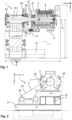
- the Figure 1 shows a side sectional view through a drive machine 1 according to the invention, which comprises a drive shaft 3 and an electric motor 2 designed as a synchronous machine.
- a drive machine 1 which comprises a drive shaft 3 and an electric motor 2 designed as a synchronous machine.
- the drive shaft 3 is designed as a belt shaft and drives a total of five belts 5, which are designed as flat belts.
- the drive shaft 3 is mounted on both sides in respective bearings 4a and 4b and can be driven by the electric motor 2.
- a rotor 6 of the electric motor 2 which carries permanent magnets, is connected gearless and rotationally fixed to the drive shaft 3 via a detachable coupling 7.
- the rotor 6 is designed as a hollow shaft 11 on the side of the drive shaft 3.
- the rotor 6 is designed as a solid shaft 25.
- an optical encoder 21 in the form of an angle encoder is mounted on the front side of the rotor 6, more precisely on the solid shaft 25, so that the current position of the rotor 6 can be detected by sensor.
- the drive shaft 3 forms a pin 12 on the motor side, which is inserted into the rotor 6, or more precisely into the hollow shaft 11.
- the pin 12 or the axis of rotation 15 of the drive shaft 3 defines the axis of rotation 14 of the rotor 6 of the electric motor 2.
- the drive shaft 3 could also be designed as a hollow shaft 11 on the motor side.
- the rotor 6 would form a pin 12, which then engages in the drive shaft 3.
- an analogous clamping coupling 7, which is shown in the figures, could be used, only in the opposite installation direction.
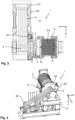
- the electric motor 2 is thus suspended freely in space on the drive shaft 3 by means of the coupling 7, whereby the drive shaft 3 is in turn supported on a support structure 27 via the bearings 4a, 4b.
- the drive shaft 3 thus carries the electric motor 2.
- the two bearings 4a and 4b of the drive shaft 3 thus not only absorb the forces that are transmitted to the drive shaft 3 via the belts 5, but also the entire weight of the electric motor 2.
- the electric motor 2 does have several support feet 9, which serve to temporarily safely park the electric motor 2; however, when mounted, these support feet 9 hang in the air, as can be seen in the views of the Figure 4 and Figure 5 is clearly visible.
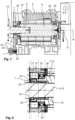
- the clutch 7 establishes a rotationally fixed connection between the drive shaft 3 and the rotor 6 by means of frictional engagement and without any form fit.
- the clutch 7 has no elastic elements whatsoever.
- the coupling 7 is designed as a clamping coupling and comprises a clamping element 16 and an associated counter-clamping element 17, which are axially clamped against each other by means of a screw connection 20.
- the (radially outer) clamping element 16 forms an inner cone 18, on which an outer cone 19 rests, which is formed by the (radially inner) counter-clamping element 17.
- These elements 17, 18, 20 thus form a ring clamping element.
- the inner counter-clamping element 17 is supported axially on a step 22, which is formed on the outside circumference in the drive shaft 3, in the area of the coupling 7.
- the clamping coupling 7 offers a conical coupling surface 30, which produces the desired frictional connection.
- a coupling surface 30 of the coupling 7, which transmits a drive torque of the electric motor 2 to the drive shaft 3, i.e. just the contact surface between the inner cone 18 and the outer cone 19, which provides the desired frictional connection, is arranged within the housing 8 of the electric motor 2.
- the coupling 7 is offset so far in the axial direction into the electric motor 2 that the said coupling surface 30 penetrates a radial plane in which the Figures 7 and 8 A-bearing 23 of the electric motor 2, which supports the rotor 6 (compare the dotted lines in Figure 8 ).
- an assembly gap 13 is kept free between the motor-side bearing 4b of the drive shaft 3 and the electric motor 2. This makes it possible to tighten the coupling 7 using hand tools when assembling the electric motor 2 on the drive shaft 3 and to loosen it again later, since the assembly gap 13 is designed to be sufficiently large to Hand tools to access the screw connection 20 of the coupling 7.
- a torque support 10 can also be seen.
- the torque support 10 has a pin 32 which is connected to the housing 8 of the electric motor 2 by means of a screw connection 20 (see Figure 7 ).
- the pin 32 is mounted in a bearing 4 of the torque support 10 so that it can rotate and move axially.
- the torque support 10 is mounted on the support structure 27 with a second bearing 4. Due to the two bearings 4 of the torque support 9, it can indeed determine an angular position of the housing 8 of the electric motor 2 in relation to a rotation axis 14 of the electric motor 2 (cf. Fig. 1 ) and thus prevent the housing 8 from rotating when the electric motor 2 is energized.
- the torque support 10 cannot determine any other degrees of freedom of the position of the electric motor 2 in space and also cannot absorb any axial forces in relation to the axis of rotation 15 of the drive shaft 3 (cf. Fig. 7 ). This avoids overdetermination and the torque support 10 only determines the angular position of the electric motor 2. Otherwise, the electric motor 2 is suspended freely in space on the drive shaft 3. As can be seen in Figure 6 detects, the torque support 10 is arranged in the mounting gap 13.
- the drive machine 1 also comprises a deflection roller 28, which deflects the total of five carrying belts 5, whereby other numbers of belts 5 can also be used.
- the deflection roller 28 can be moved on the support structure 27 so that a distance of the deflection roller 28 to the drive shaft 2 (in the x-direction in Figure 2 ) is adjustable. Also in the Figures 3 and 4 both positions of the single pulley 28 are illustrated (note the block arrows there too).
- a first belt side 33 can run to the elevator car or to a counterweight.
- the second belt side 34 can then run to the counterweight or to the car, depending on the design of the elevator shaft.
- the drive machine 1 according to the invention can thus be used in different elevator configurations.
- the drive machine 1 also includes a braking device 26 for braking the drive shaft 3.
- This braking device 26 is designed as an electromagnetic holding brake and has a brake disk 29 which is connected to the drive shaft 3 in a rotationally fixed manner. The brake shoes of the braking device 26 thus act on the brake disk 29 and thereby brake the drive shaft 3 and can also hold it in a certain rotational position.
- the braking device 26 is arranged between the two-sided bearings 4a and 4b of the drive shaft 3 and thus just on the output side of the clutch 7 (i.e. on the side of the drive shaft 3 and not on the side of the electric motor 2). Even if, for example, the frictional engagement of the If the clutch 7 were to fail and thus the rotationally fixed connection between the rotor 6 and the drive shaft 3 were to be broken, the braking device 26 can hold the drive shaft 3 securely.
- the braking device 26 is designed in such a way that the holding force is exerted in the de-energized state (due to a mechanical return element).
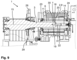
- FIG. 9 shows a further possible embodiment of a drive machine 1 according to the invention, but here no separate ring clamping element is used as a coupling 7, but the coupling 7 is formed directly by the drive shaft 3 and the rotor 6.
- the rotor 6 is again designed as a hollow shaft 11 on the drive side and thus offers a receptacle into which the drive shaft 3 is inserted, i.e. the electric motor 2 is plugged onto the drive shaft 3 here.
- the rotor 6 forms an inner cone 18 which fits an outer cone 19 which the drive shaft 3 forms at its motor-side end.
- a conical coupling surface 30 is thus formed between the drive shaft 3 and the rotor 6.
- a tightening screw 31 which is arranged centrally on and along the axis of rotation 14 of the rotor 6, is led through a passage in the rotor 6 to the drive shaft 3 and there engages in a thread in the drive shaft 3.
- the tightening screw 31 rests on a step/shoulder 22 formed on the rotor 6.
- a tightening force can be generated which pulls the rotor 6, more precisely its inner cone 18, onto the outer cone 19 of the drive shaft 3 or the drive shaft 3 onto the rotor 6, depending on which part is held.
- the tightening force creates a frictional connection between the drive shaft 3 and the rotor 6, whereby the desired rotationally fixed connection and thus a direct drive of the drive shaft 3 is achieved.
- the conical Coupling surface 30 of the rotor 6 is centered on the drive shaft 3 so that the rotation axis 14 of the rotor 6 and the rotation axis 15 of the drive shaft 3 coincide.
- the inner cone 18 could also be designed on the drive shaft 3, for example.
- the rotor 6 could be inserted into the drive shaft 3 and the frictional connection to the drive shaft 3 could be established by means of a suitable outer cone 19 on the drive-side end of the rotor 6.
- the tightening screw 31 could also be, for example (in Figure 9 from left to right) through a passage in the drive shaft 3 into a thread that is formed in the rotor 6.
- the drive shaft 3 would thus be designed (at least in sections) as a hollow shaft 11.
Landscapes
- Engineering & Computer Science (AREA)
- Civil Engineering (AREA)
- Mechanical Engineering (AREA)
- Structural Engineering (AREA)
- Connection Of Motors, Electrical Generators, Mechanical Devices, And The Like (AREA)
Description
- Die Erfindung betrifft eine Antriebsmaschine für einen Aufzug, wobei die Antriebsmaschine einen Elektromotor sowie eine Antriebswelle umfasst und wobei die Antriebswelle mittels des Elektromotors antreibbar ist und zudem beidseitig in jeweiligen Lagern gelagert ist. Die Antriebswelle kann hierbei insbesondere zum Antreiben wenigstens eines Riemens, beispielsweise eines Flachriemens oder eines Profil-Riemens, ausgebildet sein. Die Antriebswelle kann somit insbesondere als Riemenwelle ausgestaltet sein.
- Derartige Antriebsmaschinen bzw. Antriebsanordnungen werden bereits im Stand der Technik genutzt, um Aufzugskabinen in einem Aufzugsschacht zu bewegen, wobei die Verwendung von Flach- oder Profilriemen als Tragmittel gegenüber klassischen runden Tragseilen den wesentlichen Vorteil hat, dass nicht mehr Treibscheiben mit entsprechend großem Durchmesser (typischerweise größer 500 mm) erforderlich sind, sondern dass aufgrund der besseren Traktion zwischen der Antriebswelle und dem Riemen die Antriebswelle einen vergleichsweise geringen Durchmesser (von typischerweise kleiner 300 mm) aufweisen kann. Dadurch verringern sich auch die Anforderungen an das Drehmoment, welches der Elektromotor zum Antreiben der Antriebswelle zur Verfügung stellen muss, sodass der Elektromotor insbesondere getriebelos ausgebildet werden kann.
- Ein weiterer aktueller Trend bei Aufzügen besteht darin, dass die von Kunden gewünschten Anforderungen in Bezug auf die Geschwindigkeit und die zu bewegenden Nutzlasten ansteigen, sodass sich im Betrieb Belastungsspitzen von über 10 t ergeben können, die auf die Antriebswelle, vermittelt über die Riemen, einwirken. Gleichzeitig steht bei Aufzügen die Sicherheit der transportierten Personen an oberster Priorität. Die Sicherheit im Betrieb des Aufzugs muss somit in jedem Fall gewährleistet sein, insbesondere müssen technische Vorkehrungen getroffen werden, um ein Versagen des Antriebsstrangs zu verhindern. In der konkreten Anwendung muss die Antriebsmaschine somit einerseits in der Lage sein, hohe Kräfte aufzunehmen und andererseits müssen die für einen Aufzug wichtigen Sicherheitskriterien eingehalten werden, insbesondere muss ein Bruch im Antriebsstrang zwischen Elektromotor und Antriebswelle unter allen Umständen vermieden werden.
- Weiteren relevanten technologischen Hintergrund für die Erfindung bilden insbesondere die Veröffentlichungen
WO 2009/075670 A1 ,DE 10 2016 120 645 A1 undWO 2019/121955 A1 , wobeiWO 2009/075670 A1 eine Antriebsmaschine für einen Aufzug offenbart mit einem Elektromotor und einer mittels dem Elektromotor antreibbaren und gelagerten Treibscheibe, und wobei eine Kupplung vorgesehen ist, über welche der Elektromotor mit der Treibscheibe mechanisch kuppelbar ist, sodass sich die Treibscheibe in Reaktion auf eine Bewegung des Elektromotors dreht. - Von diesem technischen Hintergrund ausgehend liegt der Erfindung die Aufgabe zugrunde, eine Antriebsmaschine bereitzustellen, die leistungsfähig und sicher ist und aber gleichzeitig auch einfach transportierbar und montierbar ist.
- Zur Lösung dieser Aufgabe sind erfindungsgemäß bei einer Antriebsmaschine die Merkmale von Anspruch 1 vorgesehen. Insbesondere wird somit erfindungsgemäß zur Lösung der Aufgabe bei einer Antriebsmaschine der eingangs genannten Art vorgeschlagen, dass ein Rotor des Elektromotors getriebelos und drehfest mit der Antriebswelle über eine lösbare Kupplung verbunden ist und dass ferner der Elektromotor mittels der Kupplung frei im Raum an der Antriebswelle aufgehängt ist. Somit kann also bevorzugt die Antriebswelle den Elektromotor tragen.
- Mittels der Kupplung wird somit ein Direktantrieb der Antriebswelle durch den Elektromotor realisiert.
- Aufgrund der freien Aufhängung des Elektromotors an der Antriebswelle, zentriert die Antriebswelle die Rotationsachse des Rotors des Elektromotors. Durch den Verzicht auf eine den Elektromotor tragende Unterkonstruktion, wie etwa aufwändige Pendelfüße oder dergleichen, wird auch eine Überbestimmung vermieden, sodass sich im Betrieb keine gefährlichen mechanischen Spannungen aufbauen können. Zur Zwischenlagerung kann der Elektromotor, genauer dessen Gehäuse, zwar Aufstellfüße aufweisen. Nach erfolgter Montage des Elektromotors an der Antriebswelle hängen diese Aufstellfüße jedoch in der Luft.
- Gerade bei größerer Dimensionierung des Elektromotors (aufgrund von zur Verfügung zu stellenden hohen Nenndrehmomenten) besteht ein wesentlicher Vorteil einer solchen Ausgestaltung darin, dass der Elektromotor, genauer dessen Rotor, und die Antriebswelle einfach demontierbar und getrennt voneinander an den Aufstellungsort der Antriebsmaschine transportiert werden können. Hierdurch wird also der Transport der Antriebsmaschine vereinfacht. Zudem kann die Antriebswelle wesentlich kürzer ausgebildet werden als bei einstückiger Ausbildung mit dem Rotor des Elektromotors. Auch dies erleichtert die Montage der Antriebsmaschine am Einsatzort.
- Die Kupplung zwischen dem Rotor und der Antriebswelle kann dabei so ausgestaltet sein, dass entweder der Rotor in die Antriebswelle oder die Antriebswelle in den Rotor eingesteckt ist. Mit anderen Worten kann also bei der Montage der Antriebsmaschine der Elektromotor auf die Antriebswelle aufgesteckt oder in die Antriebswelle eingesteckt werden beziehungsweise nach erfolgter Montage sein. Hierbei kann die Antriebswelle bereits ortsfest mit Hilfe einer Tragkonstruktion installiert sein, wobei die Tragkonstruktion die Lager trägt, die die Antriebswelle lagern.
- Die Antriebswelle kann somit als eine Riemenwelle ausgestaltet sein und mehrere nebeneinander liegende Laufflächen (als Traktionsfläche für den jeweiligen Riemen) aufweisen, die jeweils zum Antrieb eines Riemens (der die jeweilige Aufzugskabine als Tragmittel trägt) ausgestaltet sind.
- Generell ist die aufgrund der Kupplung gegebene einfache Demontierbarkeit des Elektromotors auch deshalb von Vorteil, weil eine unabhängige Prüfung der beiden miteinander über die lösbare Kupplung verbundenen Einheiten der Antriebsmaschine, nämlich auf der einen Seite eine die Antriebswelle tragende (und Haltelasten aufnehmende) Tragkonstruktion und auf der anderen Seite der frei an der Antriebswelle aufgehängte Elektromotor, möglich ist. Insbesondere können dadurch diese jeweiligen Bestandteile der Antriebsmaschine an unterschiedlichen Standorten gefertigt, geprüft und versandt werden.
- Es versteht sich, dass bei einer solchen freien Aufhängung des Elektromotors an der Antriebswelle, diejenigen Lager, die die Antriebswelle lagern, nicht nur erhebliche Nutzlasten aufnehmen müssen, die im Betrieb des Aufzugs über die Riemen auf die Antriebswelle übertragen werden, sondern auch die Kräfte, die durch die gesamte Gewichtskraft des Elektromotors über die besagte Kupplung auf die Antriebswelle wirken. Diese Kräfte erzeugen insbesondere ein Biegemoment, welches die Lager der Antriebswelle aufnehmen müssen. Da die Gewichtskraft aber oftmals einen Faktor fünf kleiner ausfällt als die Spitzen der Nutzlasten, die beim Betrieb des Aufzugs auftreten, können diese Kräfte durch entsprechende Dimensionierung der Lager aufgefangen werden.
- Ein weiterer Vorteil dieser Konstruktion besteht darin, dass der Elektromotor - aufgrund der freihängenden Konstruktion - frei von einem Maschinenrahmen ausgestaltet werden kann. Das Motorgehäuse kann somit die einzige Struktur sein, die den Elektromotor nach außen abgrenzt.
- Die freie Aufhängung hat den Vorteil, dass der Elektromotor spannungsfrei auf die Antriebswelle ausgerichtet werden kann. Dadurch kann eine Fehlausrichtung und somit eine Wiegebelastung des Antriebsstrangs der Antriebsmaschine, insbesondere im Bereich der Kupplung, (während des Betriebs) vermieden werden. Zudem muss auch keine aufwändige Unterkonstruktion vorhanden sein, zu der der Elektromotor aufwändig ausgerichtet und von welcher dieser getragen wird.
- Der Rotor kann innerhalb des Elektromotors in an sich bekannter Weise durch je ein Lager auf der A-(Abtriebsseite) bzw. B-Seite gelagert sein.
- Zur Lösung der eingangs genannten Aufgabe können ergänzend zu den bislang diskutierten Merkmalen die Merkmale von Anspruch 2 vorgesehen sein. Demnach kann die Antriebsmaschine gemäß Anspruch 1 zusätzlich dadurch gekennzeichnet sein, dass mindestens eine Bremsvorrichtung zum Abbremsen der Antriebswelle abtriebsseitig zu der Kupplung, also vorzugsweise zwischen den beidseitigen Lagern der Antriebswelle, angeordnet ist.
- Eine solche Anordnung der mindestens einen Bremsvorrichtung hat Vorteile in Bezug auf die einfache Ausgestaltung der Antriebsmaschine, da die Sicherheit auch dann noch gewährleistet bleibt, wenn die Kupplung nur mittels Reibschluss eine drehfeste Verbindung zwischen dem Rotor und der Antriebswelle bereitstellt. Denn im Falle eines Versagens dieses Reibschlusses kann die von der Antriebsmaschine über die Riemen getragene Last durch Festhalten der Antriebswelle sicher in Position gehalten werden, unabhängig von der Position des Rotors des Elektromotors, d.h. auch bei Versagen der Kupplung.
- Um sehr große Lasten von mehreren Tonnen sicher festhalten zu können, kann die Bremsvorrichtung als Zangen- und/oder Scheibenbremse ausgestaltet sein. Hierbei kann die jeweilige Bremsvorrichtung auch mehrere Bremsbacken umfassen.
- Anspruch 3 beschreibt eine weitere mögliche Ausgestaltung einer erfindungsgemäßen Antriebsmaschine: Somit kann sich die Antriebsmaschine gemäß Anspruch 1 zusätzlich auch dadurch auszeichnen, dass eine Kupplungsfläche der Kupplung konusförmig ausgebildet ist. Aufgrund der Konusform kann ein Reibschluss im Bereich der Kupplungsfläche erzeugt werden, der die gewünschte drehfeste Verbindung zwischen Antriebswelle und Rotor herstellt. Ein solcher Reibschluss kann bevorzugt erzielt sein, indem ein Außenkonus, vorzugsweise mittels einer Verschraubung, auf einen Innenkonus festgezogen ist. Der Außenkonus kann zum Beispiel von der Antriebswelle und der Innenkonus von dem Rotor ausgebildet sein. Es ist aber genauso gut möglich, dass der Außenkonus von dem Rotor ausgebildet ist und der Innenkonus von der Antriebswelle ausgebildet ist. Ferner kann der Innen- und der Außenkonus alternativ auch von jeweiligen separaten Elementen einer Spannkupplung bereitgestellt werden, wie noch genauer erläutert werden wird.
- Die erwähnte Verschraubung, die den Außenkonus auf den Innenkonus festzieht, kann beispielsweise mittels wenigstens einer Anzugschraube erzielt sein, die in Richtung einer Drehachse der Antriebswelle ausgerichtet ist. Dadurch können axiale Anzugskräfte erzeugt werden, die aufgrund der Konusform der Kupplungsfläche einerseits den gewünschten Reibschluss und damit die drehfeste Verbindung zwischen dem Rotor und der Antriebswelle herstellen und andererseits den Rotor zur Antriebswelle zentrieren. In diesem Fall kann also gerade die Rotationsachse des Rotors mit der Drehachse der Antriebswelle zusammenfallen.
- Die wenigstens eine Anzugschraube kann sich dabei auf einer jeweiligen Schulter beziehungsweise Stufe abstützen, die dasjenige Element (Rotor oder Antriebswelle) ausbildet, welches den Innenkonus ausbildet und/oder in ein Gewinde eingreifen, welches in demjenigen Element (Rotor oder Antriebswelle) ausgebildet ist, welches den Außenkonus ausbildet.
- Wird der Innenkonus beispielsweise am Rotor ausgebildet, so kann im Rotor eine entsprechende Durchführung ausgebildet sein, durch die die Anzugschraube hindurchgeführt ist, damit diese in ein Gewinde in der Antriebswelle eingreifen und so die Antriebswelle (die in diesem Fall den Außenkonus ausbildet) auf den Rotor festziehen kann. Selbstverständlich ist auch eine umgekehrte Realisierung möglich: In diesem Fall kann wenigstens eine Anzugsschraube antriebseitig durch eine Durchführung in der Antriebswelle hindurchgeführt sein, um in ein im Rotor ausgebildetes Gewinde einzugreifen.
- Zur Bereitstellung einer Anzugskraft kann zum Beispiel eine zentral auf der Rotationsachse angeordnete Anzugschraube verwendet werden; es können, alternativ oder ergänzend, aber auch kollinear zur Rotationsachse angeordnete Anzugsschrauben vorgesehen sein.
- Eine erfindungsgemäße Antriebsmaschine kann sich somit ergänzend zu den zuvor erläuterten Merkmalen dadurch auszeichnen, dass der Rotor auf einer Seite der Antriebswelle als Hohlwelle und auf einer gegenüberliegenden Seite als Vollwelle ausgebildet ist. Diese Ausgestaltung hat neben einer einfachen Fertigung und gleichzeitig robusten Verbindung zwischen Rotor und Antriebswelle den Vorteil, dass vergleichsweise kleine und damit kostengünstige, vorzugsweise optische, Drehgeber an die vom Rotor ausgebildete Vollwelle (auf der B-Seite des Elektromotors) montiert werden können.
- Weitere vorteilhafte Ausführungen der Antriebsmaschine sind in den Unteransprüchen beschrieben und werden im Folgenden erläutert:
Gemäß einer vorteilhaften Ausgestaltung kann vorgesehen sein, dass die Kupplung zumindest teilweise innerhalb eines Gehäuses des Elektromotors angeordnet ist. Insbesondere kann dabei eine Kupplungsfläche der Kupplung (zumindest teilweise bevorzugt jedoch vollständig) innerhalb eines Gehäuses des Elektromotors angeordnet sein. Diese Kupplungsfläche kann somit ein Antriebsmoment des Elektromotors auf die Antriebswelle übertragen. Die Anordnung der Kupplung zumindest teilweise innerhalb des Gehäuses des Elektromotors hat den Vorteil, dass eine Beabstandung zwischen dem Gehäuse des Elektromotors und einer Tragkonstruktion, die die Lager der Antriebswelle trägt, als ein Montagespalt nur so groß ausgebildet werden muss, dass gerade ein Werkzeug (z.B. Drehmomentschlüssel) zur Montage bzw. Demontage der durch die Kupplung bereitgestellten Kupplungsverbindung hineinpasst. Dadurch wird axialer Bauraum eingespart, sodass der axiale Abstand zwischen dem Elektromotor und dem motorseitigen Lager der Antriebswelle so klein wie möglich gewählt werden kann. Dies hat Vorteile, um die mechanische Belastung der Lager zu verringern, was beispielsweise bei einem Eigengewicht des Motors von 1.5 Tonnen von erheblichem Vorteil ist. - Für eine einfache Fertigung des Rotors und der Antriebswelle ist es bevorzugt, wenn die Kupplung eine drehfeste Verbindung zwischen der Antriebswelle und dem Rotor mittels Reibschluss und/oder formschlussfrei bereitstellt bzw. herstellt. Bevorzugt weist die Kupplung dabei keine elastischen Elemente auf, sodass die Kupplung spielfrei ein Antriebsmoment des Elektromotors auf die Antriebswelle übertragen kann.
- Eine besonders bevorzugte Ausgestaltung sieht vor, dass die Kupplung ein Spannelement und ein Gegenspannelement aufweist, d.h. die Kupplung kann als eine Spannkupplung ausgestaltet sein. Das Spannelement und das Gegenspannelement können axial gegeneinander verspannbar bzw. verspannt sein, wobei diese Verspannung bevorzugt mittels einer Verschraubung erzielt werden kann. Das Spannelement kann ferner einen Innenkonus ausbilden, auf dem ein Außenkonus des Gegenspannelements aufliegt (in montiertem Zustand). Somit kann die Kupplung insbesondere als Ringspannelement ausgebildet sein. Bei derartigen Ausgestaltungen kann das Spannelement und das Gegenspannelement somit separat zur Antriebswelle und zum Rotor ausgebildet sein. Auch solche separate Spann- und Gegenspannelemente können aber eine wie zuvor beschrieben konusförmige Kupplungsfläche ausbilden und diese kann auch (zumindest teilweise bevorzugt jedoch vollständig) innerhalb eines Gehäuses des Elektromotors angeordnet sein (im montierten Zustand).
- Bevorzugt ist dabei eine axiale Spannrichtung der Kupplung entlang einer Rotationsachse des Elektromotors ausgerichtet.
- Die Verwendung einer Spannkupplung hat beispielsweise gegenüber einer Klauenkupplung den Vorteil, dass sich nicht durch Verschleiß oder Ermüdung ein Spiel einstellen kann. Dadurch kann die durch die Kupplung hergestellte mechanische Verbindung zwischen Rotor und Antriebswelle weitgehend wartungsfrei über lange Zeiträume sicher betrieben werden.
- Solch ein Spannelement, insbesondere falls als Konus-Spannelement ausgestaltet, kann somit eine Innenspannverbindung bereitstellen, mit der sich der Rotor des Elektromotors spielfrei auf der Antriebswelle (bei der Montage der Antriebsmaschine) befestigen lässt. Hierbei kann sowohl der Rotor als auch die Antriebswelle im Kupplungsbereich rotationssymmetrisch ausgestaltet werden, was die Fertigung vereinfacht. Auf eine formschlüssige Verbindung kann somit verzichtet werden. Gerade Ringspannelemente wurde bislang beispielsweise für die Befestigung von Ketten-, Schwungrädern, Hebeln, Riemen-, Bremsscheiben oder Förderbandtrommeln eingesetzt.
- Bevorzugt kann die Antriebswelle oder aber der Rotor (je nach Ausgestaltung) eine Stufe ausbilden, die als mechanischer Anschlag für das radial innenliegende Gegenspannelement dient.
- Um die Montage des Elektromotors auf der Antriebswelle zu vereinfachen, kann vorgesehen sein, dass zwischen einem motorseitigen Lager der Antriebswelle und dem Elektromotor ein Montagespalt ausgebildet bzw. freigehalten ist (im fertigmontierten Zustand der Antriebsmaschine). Dadurch kann erreicht werden, dass die Kupplung mittels Handwerkzeugen bei der Montage festgezogen und später auch wieder (auf dieselbe Weise) gelöst werden kann. Der Montagespalt kann zum Beispiel 10 cm breit oder sogar noch schmaler ausgestaltet sein.
- Eine Kupplungsfläche der Kupplung (also insbesondere die zuvor erwähnte Kupplungsfläche) kann so positioniert sein, dass sie in axialer Richtung eine Radialebene durchstößt, in welcher ein A-Lager des Elektromotors angeordnet ist, welches den Rotor lagert. Mit anderen Worten kann somit die Kupplung axial in einem Bereich ausgestaltet sein, in welchem der Rotor des Elektromotors von dem A-Lager gelagert ist. Eine solche Anordnung der Kupplung hat den Vorteil, dass der Hebelarm, der zwischen der Kupplungsfläche und dem Schwerpunkt des Elektromotors besteht, verkürzt werden kann. Dadurch kann die aufgrund der Gewichtskraft des Elektromotors auf die Kupplung wirkende mechanische Belastung reduziert werden.
- Ferner ist es vorteilhaft, wenn die Kupplung in axialer Richtung in ein Gehäuse des Elektromotors hinein versenkt ist. Dies kann insbesondere derart ausgestaltet sein, dass das Gehäuse, in axialer Richtung und auf die Antriebswelle hin, die Kupplung übersteht.
- Durch das Zurückversetzen der Kupplung in axialer Richtung weg von der Antriebswelle wird einerseits erreicht, dass der Montagespalt schmaler ausgebildet werden kann, was die Länge der gesamten Anordnung in axialer Richtung reduziert. Andererseits kann so die mechanische Belastung der Kupplung reduziert werden.
- Gemäß einer möglichen Ausgestaltung ist der Rotor antriebswellenseitig als Hohlwelle ausgebildet und die Antriebswelle bildet einen Zapfen aus, der in den Rotor eingreift. Dadurch kann der Zapfen der Antriebswelle eine Rotationsachse des Rotors (im Raum) festlegen. Der Rotor und damit der Elektromotor wird in diesem Fall bei der Montage auf den Zapfen der Antriebswelle aufgesteckt.
- Eine hierzu alternative Ausgestaltung sieht vor, dass die Antriebswelle motorseitig als Hohlwelle ausgebildet ist und der Rotor des Elektromotors einen Zapfen ausbildet, der in die Antriebswelle eingreift. Auch in diesem Fall kann die Antriebswelle die Rotationsachse des Rotors festlegen. Der Rotor und damit der Elektromotor wird in diesem Fall bei der Montage mit seinem Zapfen in die Antriebswelle eingesteckt.
- Mit anderen Worten kann also der besagte Zapfen sowohl motorseitig als auch auf der Seite der Antriebswelle (d. h. von dieser) ausgebildet werden. Die Wahl der Variante kann beispielsweise abhängig davon getroffen werden, in welchen anderen Antriebsmaschinen der Elektromotor noch zum Einsatz kommen soll.
- Um zu verhindern, dass sich das Motorgehäuse des Elektromotors beim Bestromen des Elektromotors mit dreht, kann eine Winkelposition eines Gehäuses des Elektromotors in Bezug auf eine Rotationsachse des Elektromotors über eine Drehmomentstütze festgelegt sein. Dadurch kann insbesondere eine Winkelposition eines Stators des Elektromotors festlegt werden/sein. Hierbei ist es bevorzugt, wenn die Drehmomentstütze über wenigstens ein Lager mit dem Gehäuse des Elektromotors verbunden ist. Denn in diesem Fall kann die Drehmomentstütze ausschließlich die Winkelposition festlegen, aber gerade keine sonstigen Freiheitsgrade einer Position des Elektromotors im Raum. Insbesondere kann dann die Drehmomentstütze keine Axialkräfte in Bezug auf eine Drehachse der Antriebswelle aufnehmen. Die Drehmomentstütze kann ferner bevorzugt in dem erwähnten Montagespalt angeordnet sein.
- Die Drehmomentstütze verhindert somit lediglich ein Mitdrehen des Motorgehäuses und damit eines Stators des Elektromotors, wenn der Elektromotor bestromt wird. Die Drehmomentstütze fängt jedoch nicht die Gewichtskraft des Elektromotors ab, weswegen die Drehmomentstütze auch typischerweise erst nach erfolgter Montage des Elektromotors auf der Antriebswelle montiert werden kann.
- Die Antriebsmaschine kann auch eine Tragkonstruktion umfassen, die die Antriebswelle (genauer die Lager der Antriebswelle) trägt. Bevorzugt trägt die Tragkonstruktion ferner wenigstens eine Umlenkrolle, wobei die Umlenkrolle dem Umlenken des wenigstens einen Riemens der Antriebsmaschine dienen kann. Um die Antriebsmaschine mit unterschiedlichen Aufzügen nutzen zu können ist es dabei vorteilhaft, wenn ein Abstand der Umlenkrolle zu der Antriebswelle (mithilfe der Tragkonstruktion) einstellbar ist.
- Die zuvor erwähnte Drehmomentstütze kann dabei an der Tragkonstruktion abgestützt sein. In diesem Fall kann also die Tragkonstruktion ein Gegenmoment zum Antriebsmoment des Elektromotors bereitstellen. Abgesehen von der Drehmomentstütze und der notwendigen Verbindung zwischen der Antriebswelle und dem Rotor des Elektromotors, kann der Elektromotor jedoch sonst keinerlei Verbindung zu der Tragkonstruktion aufweisen und somit vollständig frei im Raum hängend montiert sein.
- Die eingangs erwähnte Bremsvorrichtung kann insbesondere als eine elektromechanische Haltebremse zum Festhalten der Antriebswelle ausgestaltet sein. Hierbei kann eine Bremsscheibe der Bremsvorrichtung drehfest mit der Antriebswelle verbunden sein. Um Sicherheitsnormen zu erfüllen, kann die elektromechanische Haltebremse so ausgestaltet sein, dass sie nur in bestromten Zustand lüftet, hingegen im unbestromten Zustand bremst und in diesem Fall die Antriebswelle sicher festhalten kann (also insbesondere bei Verlust der Stromversorgung).
- Der Elektromotor der Antriebsmaschine kann bevorzugt ein permanentmagneterregter Elektromotor sein. Insbesondere kann also der Rotor des Elektromotors Permanentmagnete aufweisen. Ferner ist es für einen effizienten Betrieb vorteilhaft, wenn der Elektromotor zudem als eine Synchronmaschine ausgestaltet ist.
- Die Erfindung wird nun anhand von Ausführungsbeispielen näher beschrieben, ist aber nicht auf diese Ausführungsbeispiele beschränkt. Für den Fachmann ergeben sich weitere Ausbildungen der Erfindung aus der nachfolgenden Beschreibung eines bevorzugten Ausführungsbeispiels unter Berücksichtigung der vorherigen allgemeinen Beschreibung, sowie den Merkmalen, die den Ansprüchen und den Zeichnungen entnommen werden können.
- Es zeigt:
- Fig. 1
- Ein seitliche Schnittansicht (entgegen der x-Richtung) auf eine erfindungsgemäße Antriebsmaschine, wobei die Antriebswelle und der Rotor des Elektromotors mittig geschnitten sind,
- Fig. 2
- eine Seitenansicht von vorne entgegen der y-Richtung auf die Antriebsmaschine der
Figur 1 , - Fig. 3
- eine Aufsicht von oben (in z-Richtung) auf die Antriebsmaschine der
Figur 1 , - Fig. 4
- eine perspektivische Ansicht auf die Antriebsmaschine der
Figur 1 , - Fig. 5
- eine weitere perspektivische Sicht auf die Antriebsmaschine der
Figur 1 von Schräg hinten mit Blick auf den frei aufgehängten Elektromotor, - Fig. 6
- eine Detail der Schnittansicht der
Figur 1 mit Blick auf den Kupplungsbereich zwischen Antriebswelle und Elektromotor, - Fig. 7
- eine Detail der Schnittansicht der
Figur 1 mit Blick auf die Rotorwelle des Elektromotors, - Fig. 8
- weitere Details der zwischen dem Rotor des Elektromotors und der Antriebswelle ausgebildeten Kupplung und
- Fig. 9
- eine weitere mögliche Ausgestaltung einer erfindungsgemäßen Antriebsmaschine 1.
- Die
Figur 1 zeigt eine seitliche Schnittansicht durch eine erfindungsgemäße Antriebsmaschine 1, die eine Antriebswelle 3 und einen als eine Synchronmaschine ausgestalteten Elektromotor 2 umfasst. Wie aus den weiterenFiguren 2 bis 5 zu erkennen ist, die weitere Ansichten der Antriebsmaschine 1 ausFigur 1 zeigen, ist die Antriebswelle 3 als eine Riemenwelle ausgestaltet und treibt insgesamt fünf Riemen 5 an, die als Flachriemen ausgebildet sind. - Wie in der Schnittansicht der
Figur 1 zu sehen ist, ist die Antriebswelle 3 beidseitig in jeweiligen Lagern 4a und 4b gelagert und kann mittels des Elektromotors 2 angetrieben werden. Hierfür ist ein Rotor 6 des Elektromotors 2, welcher Permanentmagnete trägt, getriebelos und drehfest mit der Antriebswelle 3 über eine lösbare Kupplung 7 verbunden. In der Schnittansicht derFigur 1 und noch besser in den Detailansichten dieser Schnittansicht gemäß denFiguren 6 bis 8 ist ferner zu erkennen, dass der Rotor 6 auf der Seite der Antriebswelle 3 als Hohlwelle 11 ausgebildet ist. Auf der gegenüberliegenden Seite ist der Rotor 6 hingegen als Vollwelle 25 ausgebildet. Wie man inFigur 7 erkennt, ist ein optischer Drehgeber 21 in Form eines Winkel-Encoders stirnseitig am Rotor 6, genauer an der Vollwelle 25, montiert, damit die aktuelle Position des Rotors 6 sensorisch erfasst werden kann. - Die Antriebswelle 3 bildet hingegen motorseitig einen Zapfen 12 aus, der in den Rotor 6, also genauer in die Hohlwelle 11, eingesteckt ist. Hierbei legt gerade der Zapfen 12 bzw. die Drehachse 15 der Antriebswelle 3, die Rotationsachse 14 des Rotors 6 des Elektromotors 2 fest. Alternativ könnte aber auch die Antriebswelle 3 motorseitig als Hohlwelle 11 ausgebildet werden. In diesem Fall würde der Rotor 6 einen Zapfen 12 ausbilden, der dann in die Antriebswelle 3 eingreift. Bei einer solchen Konstruktion könnte eine analoge Spannkupplung 7, die in den Figuren gezeigt ist, verwendet werden, lediglich in umgekehrter Einbaurichtung.
- Wie gerade anhand der Ansichten der
Figur 4 und5 zu erkennen ist, ist der Elektromotor 2 somit mittels der Kupplung 7 frei im Raum an der Antriebswelle 3 aufgehängt, wobei die Antriebswelle 3 ihrerseits über die Lager 4a, 4b auf einer Tragkonstruktion 27 abgestützt ist. Somit trägt die Antriebswelle 3 den Elektromotor 2. Die beiden Lager 4a und 4b der Antriebswelle 3 nehmen somit nicht nur die Kräfte auf, die über die Riemen 5 auf die Antriebswelle 3 übertragen werden, sondern auch die gesamte Gewichtskraft des Elektromotors 2. Der Elektromotor 2 verfügt zwar über mehrere Aufstellfüße 9, die dazu dienen, den Elektromotor 2 temporär sicher abstellen zu können; im montierten Zustand hängen diese Aufstellfüße 9 jedoch in der Luft, wie in den Ansichten derFigur 4 undFigur 5 gut zu erkennen ist. - Wie die
Figur 6 und noch besser dieFigur 8 zeigen, stellt die Kupplung 7 eine drehfeste Verbindung zwischen der Antriebswelle 3 und dem Rotor 6 mittels Reibschluss und ohne jeglichen Formschluss her. Insbesondere weist die Kupplung 7 keinerlei elastische Elemente auf. - Wie die
Figur 8 zeigt, ist die Kupplung 7 als eine Spannkupplung ausgestaltet und umfasst ein Spannelement 16 und ein zugehöriges Gegenspannelement 17, die axial mittels einer Verschraubung 20 gegeneinander verspannt sind. Hierbei bildet das (radial außen liegende) Spannelement 16 einen Innenkonus 18 aus, auf dem ein Außenkonus 19 aufliegt, der von dem (radial innen liegenden) Gegenspannelement 17 ausgebildet wird. Diese Elemente 17, 18, 20 bilden somit ein Ringspannelement. Das innere Gegenspannelement 17 stützt sich dabei axial auf einer Stufe 22 ab, die außen umfangsseitig in der Antriebswelle 3, im Bereich der Kupplung 7, ausgebildet ist. Die Spannkupplung 7 bietet dabei ein konusförmige Kupplungsfläche 30, die einen gewünschten Reibschluss herstellt. - Wie man anhand der beiden gestrichelten vertikalen Linien in
Figur 8 und der Zusammenschau derFiguren 7 und 8 erkennt, ist eine Kupplungsfläche 30 der Kupplung 7, die ein Antriebsmoment des Elektromotors 2 auf die Antriebswelle 3 überträgt, also gerade die Kontaktfläche zwischen dem Innenkonus 18 und dem Außenkonus 19, die den gewünschten Reibschluss bereitstellt, innerhalb des Gehäuses 8 des Elektromotors 2 angeordnet. Die Kupplung 7 ist dabei so weit in axialer Richtung in den Elektromotor 2 hineinversetzt, dass die besagte Kupplungsfläche 30 eine Radialebene durchstößt, in welcher das in denFiguren 7 und 8 zu erkennende A-Lager 23 des Elektromotors 2 angeordnet ist, welches den Rotor 6 lagert (vergleiche dazu die gepunkteten Linien inFigur 8 ). - Wie die Detailansicht der
Figur 6 zeigt, ist zwischen dem motorseitigen Lager 4b der Antriebswelle 3 und dem Elektromotor 2 ein Montagespalt 13 freigehalten. Dies ermöglicht es, bei der Montage des Elektromotors 2 auf der Antriebswelle 3 die Kupplung 7 mittels Handwerkzeugen festzuziehen und später auch wieder zu lösen, da der Montagespalt 13 ausreichend groß ausgestaltet ist, um mit den Handwerkzeugen an die Verschraubung 20 der Kupplung 7 zu gelangen. - Ferner ist in
Figur 8 gut zu erkennen, dass die Kupplung 7 in axialer Richtung in das Gehäuse 8 des Elektromotors 2 hinein versenkt ist. Denn das Gehäuse 8 steht in axialer Richtung auf die Antriebswelle 3 hin über die Kupplung 7 über (vergleiche die gestrichelte Linie inFigur 8 ). - In den
Figuren 1 ,3 , sowie 5 bis 7 ist zudem eine Drehmomentstütze 10 zu erkennen. Die Drehmomentstütze 10 weist einen Zapfen 32 auf, der mittels einer Verschraubung 20 mit dem Gehäuse 8 des Elektromotors 2 verbunden ist (vergleicheFigur 7 ). Hierbei ist der Zapfen 32 in einem Lager 4 der Drehmomentstütze 10 drehbar und axial verschieblich gelagert. - In den
Figuren 3 und5 ist gut zu erkennen, dass die Drehmomentstütze 10 mit einem zweiten Lager 4 an der Tragkonstruktion 27 montiert ist. Aufgrund der beiden Lager 4 der Drehmomentstütze 9 kann diese zwar eine Winkelposition des Gehäuses 8 des Elektromotors 2 in Bezug auf eine Rotationsachse 14 des Elektromotors 2 festlegen (Vgl.Fig. 1 ) und damit verhindern, dass das Gehäuse 8 mit rotiert, wenn der Elektromotor 2 bestromt wird. Die Drehmomentstütze 10 kann jedoch gerade keine sonstigen Freiheitsgrade der Position des Elektromotors 2 im Raum festlegen und zudem auch keine Axialkräfte in Bezug auf die Drehachse 15 der Antriebswelle 3 aufnehmen (Vgl.Fig. 7 ). Dadurch wird eine Überbestimmung vermieden und es wird durch die Drehmomentstütze 10 ausschließlich die Winkelposition des Elektromotors 2 festgelegt. Ansonsten ist der Elektromotor 2 frei im Raum an der Antriebswelle 3 aufgehängt. Wie man gut inFigur 6 erkennt, ist die Drehmomentstütze 10 in dem Montagespalt 13 angeordnet. - Wie die
Figur 2 zeigt, umfasst die Antriebsmaschine 1 zudem eine Umlenkrolle 28, die die insgesamt fünf Tragriemen 5 umlenkt, wobei auch andere Anzahlen von Riemen 5 verwendet werden können. Wie mittels des Blockpfeils inFigur 2 illustriert ist, kann die Umlenkrolle 28 auf der Tragkonstruktion 27 verschoben werden, sodass ein Abstand der Umlenkrolle 28 zu der Antriebswelle 2 (in x-Richtung inFigur 2 ) einstellbar ist. Auch in denFiguren 3 und 4 sind beide Positionen der einzigen Umlenkrolle 28 illustriert (man beachte auch dort die Blockpfeile). - Wie die Bezugszeichen 33 und 34 in
Figur 2 zeigen, kann eine erste Riemenseite 33 zur Kabine des Aufzugs oder zu einem Gegengewicht verlaufen. Entsprechend kann dann die zweite Riemenseite 34 zum Gegengewicht beziehungsweise zur Kabine verlaufen, je nach Ausgestaltung des Aufzugsschachts. Somit kann die erfindungsgemäße Antriebsmaschine 1 in unterschiedlichen Aufzugs-Konstellationen eingesetzt werden. - In
Figur 2 undFigur 4 ist gut zu erkennen, dass die Antriebsmaschine 1 auch eine Bremsvorrichtung 26 zum Abbremsen der Antriebswelle 3 umfasst. Diese Bremsvorrichtung 26 ist als eine elektromagnetische Haltebremse ausgestaltet und weist eine Bremsscheibe 29 auf, die drehfest mit der Antriebswelle 3 verbunden ist. Die Bremsbacken der Bremsvorrichtung 26 wirken somit auf die Bremsscheibe 29 und bremsen dadurch die Antriebswelle 3 ab und können diese auch in einer bestimmten Drehposition festhalten. - Wie man in
Figur 1 sowie in denFiguren 3 und 4 erkennen kann, ist die Bremsvorrichtung 26 zwischen den beidseitigen Lagern 4a und 4b der Antriebswelle 3 angeordnet und somit gerade abtriebsseitig zu der Kupplung 7 (also auf Seite der Antriebswelle 3 und nicht auf Seiten des Elektromotors 2). Selbst dann also, wenn beispielsweise der Reibschluss der Kupplung 7 versagen sollte und somit die drehfeste Verbindung zwischen dem Rotor 6 und der Antriebswelle 3 aufgelöst wäre, kann die Bremsvorrichtung 26 die Antriebswelle 3 sicher festhalten. Hierbei ist die Bremsvorrichtung 26 gerade so ausgestaltet, dass die Haltekraft im unbestromten Zustand (aufgrund eines mechanischen Rückstellelements) ausgeübt wird. - Die
Figur 9 zeigt eine weitere mögliche Ausgestaltung einer erfindungsgemäßen Antriebsmaschine 1, wobei hier jedoch kein separates Ringspannelement als Kupplung 7 verwendet wird, sondern die Kupplung 7 direkt durch die Antriebswelle 3 und den Rotor 6 ausgebildet ist. Wie zu sehen, ist der Rotor 6 antriebsseitig erneut als Hohlwelle 11 ausgebildet und bietet so eine Aufnahme, in die die Antriebswelle 3 eingesteckt ist, d.h. der Elektromotor 2 ist hier auf die Antriebswelle 3 aufgesteckt. Am rechten Ende der Aufnahme bildet der Rotor 6 einen Innenkonus 18 aus, der zu einem Außenkonus 19 passt, den die Antriebswelle 3 an ihrem motorseitigen Ende ausbildet. Zwischen der Antriebswelle 3 und dem Rotor 6 ist somit eine konusförmige Kupplungsfläche 30 ausgebildet. Man erkennt ferner, dass eine Anzugschraube 31, die zentral auf und entlang der Rotationsachse 14 des Rotors 6 angeordnet ist, durch eine Durchführung im Rotor 6 bis zur Antriebswelle 3 hindurchgeführt ist und dort in der Antriebswelle 3 in ein Gewinde eingreift. Hierbei stützt sich die Anzugsschraube 31 auf einer Stufe/Schulter 22 ab, die am Rotor 6 ausgebildet ist. Mittels dieser Verschraubung 20 kann somit eine Anzugskraft erzeugt werden, die den Rotor 6, genauer dessen Innenkonus 18, auf den Außenkonus 19 der Antriebswelle 3 zieht beziehungsweise die Antriebswelle 3 auf den Rotor 6, je nachdem welcher Teil festgehalten wird. Durch die Anzugskraft wird ein Reibschluss zwischen der Antriebswelle 3 und dem Rotor 6 hergestellt, wodurch die gewünschte drehfeste Verbindung und damit ein Direktantrieb der Antriebswelle 3 erreicht wird. Zudem wird mittels der konusförmigen Kupplungsfläche 30 der Rotor 6 auf die Antriebswelle 3 zentriert, sodass die Rotationsachse 14 des Rotors 6 und die Drehachse 15 der Antriebswelle 3 zusammenfallen. - Selbstverständlich könnte der Innenkonus 18 beispielsweise auch an der Antriebswelle 3 ausgestaltet werden. In diesem Fall könnte der Rotor 6 in die Antriebswelle 3 eingesteckt und der Reibschluss zur Antriebswelle 3 mittels eines passenden Außenkonus 19 am antriebsseitigen Ende des Rotors 6 hergestellt werden. Die Anzugschraube 31 könnte in einem solchen Fall auch zum Beispiel (in
Figur 9 von links nach rechts) durch eine Durchführung in der Antriebswelle 3 bis in ein Gewinde geführt sein, dass im Rotor 6 ausgebildet ist. In diesem Fall wäre die Antriebswelle 3 somit (zumindest abschnittsweise) als Hohlwelle 11 ausgebildet. - Zusammenfassend wird zur einfacheren Transportierbarkeit einer Antriebsmaschine 1, die zum Bewegen einer Aufzugskabine in einem Schacht vorgesehen ist, vorgeschlagen, einen Direktantrieb derart auszugestalten, dass ein Elektromotor 2 der Antriebsmaschine 1 auf eine Antriebswelle 3, die dem Antreiben von wenigstens einem Riemen 5 (ausgestaltet als Flachriemen oder als Profil-Riemen) dient, aufgesteckt oder in die Antriebswelle 3 eingesteckt wird/ist, sodass der Elektromotor 2 freitragend an der Antriebswelle 3 aufgehängt ist. Eine solche Ausgestaltung bietet den Vorteil, dass die Antriebsmaschine 1 vergleichsweise einfach montiert/demontiert und die einzelnen Bestandteile separat voneinander zum Aufstellungsort transportiert werden können (vergleiche
Fig. 1 ) . -
- 1
- Antriebsmaschine
- 2
- Elektromotor
- 3
- Antriebswelle
- 4
- Lager
- 5
- Riemen, insbesondere Flachriemen oder Profil-Riemen
- 6
- Rotor
- 7
- Kupplung
- 8
- Gehäuse (von 2)
- 9
- Aufstellfüße (von 8, nicht genutzt in der freien Aufhängung!)
- 10
- Drehmomentstütze
- 11
- Hohlwelle
- 12
- Zapfen (von 3)
- 13
- Montagespalt
- 14
- Rotationsachse (von 2/6)
- 15
- Drehachse (von 3)
- 16
- Spannelement
- 17
- Gegenspannelement
- 18
- Innenkonus (von 16)
- 19
- Außenkonus (von 17)
- 20
- Verschraubung
- 21
- Drehgeber (insbesondere Winkel-Encoder)
- 22
- Stufe bzw. Schulter
- 23
- A-Lager (von 2, abtriebsseitig, also auf der Seite von 3)
- 24
- B-Lager (von 2)
- 25
- Vollwelle
- 26
- Bremsvorrichtung (diese kann auch mehrere Bremsvorrichtungen, insbesondere mehrere Bremsbacken, umfassen)
- 27
- Tragkonstruktion
- 28
- Umlenkrolle (für 5)
- 29
- Bremsscheibe
- 30
- Kupplungsfläche (von 7, insbesondere zwischen 16 und 17)
- 31
- Anzugsschraube
- 32
- Zapfen (von 10)
- 33
- erste Riemenseite
- 34
- zweite Riemenseite
Claims (17)
- Antriebsmaschine (1) für einen Aufzug, umfassend- einen Elektromotor (2),- eine mittels des Elektromotors (2) antreibbare und beidseitig in jeweiligen Lagern (4a, 4b) gelagerte Antriebswelle (3),- insbesondere wobei die Antriebswelle (3) zum Antreiben wenigstens eines Riemens (5), insbesondere eines Flachriemens (5) oder eines Profil-Riemens (5), ausgebildet ist,- wobei ein Rotor (6) des Elektromotors (2) getriebelos und drehfest mit der Antriebswelle (3) über eine lösbare Kupplung (7) verbunden ist, dadurch gekennzeichnet,- dass eine Winkelposition eines Gehäuses (8) des Elektromotors (2) in Bezug auf eine Rotationsachse (14) des Elektromotors (2) über eine Drehmomentstütze (10) festgelegt ist und- dass der Elektromotor (2) mittels der Kupplung (7) frei im Raum an der Antriebswelle (3) aufgehängt ist,- vorzugsweise sodass die Antriebswelle (3) den Elektromotor (2) trägt.
- Antriebsmaschine (1) nach Anspruch 1,- wobei ein Rotor (6) des Elektromotors (2) getriebelos und drehfest mit der Antriebswelle (3) über eine lösbare Kupplung (7) verbunden ist und- wobei mindestens eine Bremsvorrichtung (26) zum Abbremsen der Antriebswelle (3) abtriebsseitig zu der Kupplung (7), vorzugsweise zwischen den beidseitigen Lagern (4a, 4b) der Antriebswelle (3), angeordnet ist.
- Antriebsmaschine (1) gemäß Anspruch 1 oder Anspruch 2,- wobei ein Rotor (6) des Elektromotors (2) getriebelos und drehfest mit der Antriebswelle (3) über eine lösbare Kupplung (7) verbunden ist und- wobei eine Kupplungsfläche (30) der Kupplung (7) konusförmig ausgebildet ist,- vorzugsweise wobei ein Reibschluss im Bereich der Kupplungsfläche (30) erzeugt ist, indem ein Außenkonus (19), vorzugsweise mittels einer Verschraubung (20), auf einen Innenkonus (18) festgezogen ist.
- Antriebsmaschine (1) nach Anspruch 3, wobei- der Außenkonus (19) von der Antriebswelle (3) und der Innenkonus (18) von dem Rotor (6) ausgebildet ist oder- der Außenkonus (19) von dem Rotor (6) und der Innenkonus (18) von der Antriebswelle (3) ausgebildet ist.
- Antriebsmaschine (1) nach einem der vorhergehenden Ansprüche,- wobei ein Rotor (6) des Elektromotors (2) getriebelos und drehfest mit der Antriebswelle (3) über eine lösbare Kupplung (7) verbunden ist und- wobei der Rotor (6) auf einer Seite der Antriebswelle (3) als Hohlwelle (11) und auf einer gegenüberliegenden Seite als Vollwelle (25) ausgebildet ist.
- Antriebsmaschine (1) nach einem der vorhergehenden Ansprüche, wobei die Kupplung (7),- insbesondere eine, insbesondere die konusförmige, Kupplungsfläche (30) der Kupplung (7),zumindest teilweise innerhalb eines Gehäuses (8) des Elektromotors (2) angeordnet ist.
- Antriebsmaschine (1) nach einem der vorhergehenden Ansprüche,- wobei die Kupplung (7) eine drehfeste Verbindung zwischen der Antriebswelle (3) und dem Rotor (6) mittels Reibschluss und/oder formschlussfrei bereitstellt,- vorzugsweise wobei die Kupplung (7) keine elastischen Elemente aufweist und daher spielfrei ein Antriebsmoment des Elektromotors (2) auf die Antriebswelle (3) übertragen kann.
- Antriebsmaschine (1) nach einem der vorhergehenden Ansprüche,- wobei die Kupplung (7) ein Spannelement (16) und einen Gegenspannelement (17) aufweist, die axial, vorzugsweise mittels einer Verschraubung (20), gegeneinander verspannbar beziehungsweise verspannt sind,- vorzugsweise wobei das Spannelement (16) einen Innenkonus (18) ausbildet auf dem ein Außenkonus (19) des Gegenspannelements (17) aufliegt und/oder- wobei die Kupplung (7) als Ringspannelement ausgebildet ist.
- Antriebsmaschine (1) nach einem der vorhergehenden Ansprüche, wobei zwischen einem motorseitigen Lager (4b) der Antriebswelle (3) und dem Elektromotor (2) ein Montagespalt (13) ausgebildet ist, sodass die Kupplung (7) mittels Handwerkzeugen bei der Montage festgezogen und später auch wieder gelöst werden kann.
- Antriebsmaschine (1) nach einem der vorhergehenden Ansprüche, wobei eine, insbesondere die, Kupplungsfläche (30) der Kupplung (7) in axialer Richtung eine Radialebene durchstößt, in welcher ein A-Lager (23) des Elektromotors angeordnet ist, welches den Rotor (6) lagert.
- Antriebsmaschine (1) nach einem der vorhergehenden Ansprüche, wobei die Kupplung (7) in axialer Richtung in ein Gehäuse (8) des Elektromotors (2) hinein versenkt ist,- insbesondere derart, dass das Gehäuse (8) in axialer Richtung und auf die Antriebswelle (3) hin die Kupplung (7) übersteht.
- Antriebsmaschine (1) nach einem der vorhergehenden Ansprüche, wobei der Rotor (6) antriebswellenseitig als Hohlwelle (11) ausgebildet ist und die Antriebswelle (3) einen Zapfen (12) ausbildet, der in den Rotor (6) eingreift, insbesondere wobei der Zapfen (12) eine Rotationsachse (14) des Rotors (6) festlegt.
- Antriebsmaschine (1) nach einem der vorhergehenden Ansprüche 1 bis 9, wobei die Antriebswelle (3) motorseitig als Hohlwelle (11) ausgebildet ist und der Rotor (6) des Elektromotors (2) einen Zapfen (12) ausbildet, der in die Antriebswelle (3) eingreift, insbesondere wobei die Antriebswelle (3) die Rotationsachse (14) des Rotors (2) festlegt.
- Antriebsmaschine (1) nach einem der vorhergehenden Ansprüche,- wobei die Drehmomentstütze (10) über wenigstens ein Lager (4) mit dem Gehäuse (8) verbunden ist, sodass die Drehmomentstütze (10) ausschließlich die Winkelposition festlegt aber keine sonstigen Freiheitsgrade einer Position des Elektromotors (2) im Raum, insbesondere und keine Axialkräfte in Bezug auf eine Drehachse (15) der Antriebswelle (3) aufnehmen kann und/oder in dem Montagespalt (13) angeordnet ist.
- Antriebsmaschine (1) nach einem der vorhergehenden Ansprüche, wobei die Antriebsmaschine (1) eine Tragkonstruktion (27) umfasst, die die Antriebswelle (3), vorzugsweise und wenigstens eine, vorzugsweise in ihrem Abstand zur Antriebswelle (3) einstellbare, Umlenkrolle (28) trägt,- vorzugsweise wobei die Drehmomentstütze (10) an der Tragkonstruktion (27) abgestützt ist, insbesondere sodass die Tragkonstruktion (27) ein Gegenmoment zum Antriebsmoment des Elektromotors (2) bereitstellen kann.
- Antriebsmaschine (1) nach einem der Ansprüche 2 bis 13, wobei die Bremsvorrichtung (26) als eine elektromechanische Haltebremse zum Festhalten der Antriebswelle (3) ausgestaltet ist, vorzugsweise wobei eine Bremsscheibe (29) der Bremsvorrichtung (26) drehfest mit der Antriebswelle (3) verbunden ist.
- Antriebsmaschine (1) nach einem der vorhergehenden Ansprüche, wobei der Elektromotor (2) ein permanentmagneterregter Elektromotor (2) ist, insbesondere wobei der Rotor (6) Permanentmagnete aufweist,- vorzugsweise wobei der Elektromotor (2) als Synchronmaschine ausgestaltet ist.
Applications Claiming Priority (1)
| Application Number | Priority Date | Filing Date | Title |
|---|---|---|---|
| DE102022109725.0A DE102022109725A1 (de) | 2022-04-22 | 2022-04-22 | Modulare Antriebsmaschine für einen Aufzug |
Publications (2)
| Publication Number | Publication Date |
|---|---|
| EP4265556A1 EP4265556A1 (de) | 2023-10-25 |
| EP4265556B1 true EP4265556B1 (de) | 2025-02-12 |
Family
ID=86051865
Family Applications (1)
| Application Number | Title | Priority Date | Filing Date |
|---|---|---|---|
| EP23168005.9A Active EP4265556B1 (de) | 2022-04-22 | 2023-04-14 | Antriebsmaschine für einen aufzug |
Country Status (2)
| Country | Link |
|---|---|
| EP (1) | EP4265556B1 (de) |
| DE (1) | DE102022109725A1 (de) |
Families Citing this family (1)
| Publication number | Priority date | Publication date | Assignee | Title |
|---|---|---|---|---|
| DE102024104740A1 (de) * | 2024-02-20 | 2025-03-06 | Tk Elevator Innovation And Operations Gmbh | Riementriebeinheit für Aufzugsanlagen, Aufzugsanlage sowie Verfahren und Verwendung |
Family Cites Families (8)
| Publication number | Priority date | Publication date | Assignee | Title |
|---|---|---|---|---|
| DE19924735A1 (de) | 1999-05-31 | 2001-03-15 | Sew Eurodrive Gmbh & Co | Baureihe von Elektromotoren mit Drehzahlrückführung und Elektromotor mit Drehzahlrückführung |
| US20070056804A1 (en) | 2003-10-01 | 2007-03-15 | Frank Thielow | Lifting device especially a lift or a lifting platform |
| DE202005015876U1 (de) | 2005-10-07 | 2005-12-29 | Bullinger, Rudolf | Vorrichtung zum hilfsweisen Antrieb eines Rads |
| WO2009075670A1 (en) * | 2007-12-10 | 2009-06-18 | Otis Elevator Company | Elevator machine assembly including torque-based motor control |
| DE102010029071A1 (de) | 2010-05-18 | 2011-11-24 | Bayerische Motoren Werke Aktiengesellschaft | Radantrieb für ein Fahrzeug |
| DE102014011929A1 (de) | 2014-08-14 | 2016-02-18 | Fromm Holding Ag | Antriebseinheit für ein Umreifungsgerät |
| DE102016120645A1 (de) * | 2016-10-28 | 2018-05-03 | Logos-Innovationen Gmbh | Hebevorrichtung, insbesondere Aufzug oder Hebebühne |
| CN111491883B (zh) * | 2017-12-19 | 2022-05-27 | 蒂森克虏伯电梯创新与运营有限公司 | 电梯驱动单元 |
-
2022
- 2022-04-22 DE DE102022109725.0A patent/DE102022109725A1/de not_active Withdrawn
-
2023
- 2023-04-14 EP EP23168005.9A patent/EP4265556B1/de active Active
Also Published As
| Publication number | Publication date |
|---|---|
| DE102022109725A1 (de) | 2023-10-26 |
| EP4265556A1 (de) | 2023-10-25 |
Similar Documents
| Publication | Publication Date | Title |
|---|---|---|
| DE69909133T2 (de) | Aufzugsantrieb mit gegenläufigen rotoren | |
| EP3317222B1 (de) | Hubwindenanordnung | |
| WO2017174464A1 (de) | Antriebseinheit für eine aufzugsanlage | |
| DE69420329T2 (de) | Im Gegengewicht eingebauter Aufzugsmotor | |
| EP1667930A2 (de) | Hebevorrichtung, insbesondere aufzug oder hebebühne | |
| EP3403982A1 (de) | Flexibler maschinenrahmen | |
| EP0834463A1 (de) | Kompakt-Antrieb für Aufzüge | |
| EP2460755B1 (de) | Hebevorrichtung, insbesondere Aufzug oder Hebebühne | |
| AT507470B1 (de) | Antriebsvorrichtung für den druckbalken einer biegepresse | |
| EP3536404B1 (de) | Stützvorrichtung für getriebepaar und industrieapplikation | |
| EP4265556A1 (de) | Antriebsmaschine für einen aufzug | |
| DE102006052767B4 (de) | Außenläufermotor mit Bremse | |
| EP0673874A1 (de) | Antriebsmaschine für Aufzüge | |
| DE19906727C1 (de) | Getriebelose Aufzugsmaschine mit einem Synchron-Außenläufermotor | |
| EP0079420A1 (de) | Lagervorrichtung für die Winde des Fahrkorbes eines Personen- oder Lastenaufzuges | |
| DE102016120645A1 (de) | Hebevorrichtung, insbesondere Aufzug oder Hebebühne | |
| EP1069068A1 (de) | Kompakter Antrieb für einen Aufzug | |
| DE19511077A1 (de) | Getriebelose Treibscheiben-Fördermaschine | |
| DE102017223246A1 (de) | Aufzugsantriebseinheit | |
| DE10136030B4 (de) | Trommelantrieb für eine Fahrtreppe oder einen Fahrsteig | |
| EP2391569B1 (de) | Treibscheiben-schachtfördermaschine | |
| EP3452399A1 (de) | Hebevorrichtung, insbesondere aufzug oder hebebühne | |
| DE102021121909B3 (de) | Rotoreinheit einer elektrischen Axialflussmaschine und Elektrische Axialflussmaschine | |
| DE102016108349A1 (de) | Hebevorrichtung, insbesondere Aufzug oder Hebebühne | |
| DE19860458C1 (de) | Seiltrieb für Gebäudeaufzüge |
Legal Events
| Date | Code | Title | Description |
|---|---|---|---|
| STAA | Information on the status of an ep patent application or granted ep patent |
Free format text: STATUS: THE APPLICATION HAS BEEN PUBLISHED |
|
| PUAI | Public reference made under article 153(3) epc to a published international application that has entered the european phase |
Free format text: ORIGINAL CODE: 0009012 |
|
| AK | Designated contracting states |
Kind code of ref document: A1 Designated state(s): AL AT BE BG CH CY CZ DE DK EE ES FI FR GB GR HR HU IE IS IT LI LT LU LV MC ME MK MT NL NO PL PT RO RS SE SI SK SM TR |
|
| STAA | Information on the status of an ep patent application or granted ep patent |
Free format text: STATUS: REQUEST FOR EXAMINATION WAS MADE |
|
| 17P | Request for examination filed |
Effective date: 20231207 |
|
| RBV | Designated contracting states (corrected) |
Designated state(s): AL AT BE BG CH CY CZ DE DK EE ES FI FR GB GR HR HU IE IS IT LI LT LU LV MC ME MK MT NL NO PL PT RO RS SE SI SK SM TR |
|
| GRAP | Despatch of communication of intention to grant a patent |
Free format text: ORIGINAL CODE: EPIDOSNIGR1 |
|
| STAA | Information on the status of an ep patent application or granted ep patent |
Free format text: STATUS: GRANT OF PATENT IS INTENDED |
|
| GRAS | Grant fee paid |
Free format text: ORIGINAL CODE: EPIDOSNIGR3 |
|
| INTG | Intention to grant announced |
Effective date: 20241204 |
|
| GRAA | (expected) grant |
Free format text: ORIGINAL CODE: 0009210 |
|
| STAA | Information on the status of an ep patent application or granted ep patent |
Free format text: STATUS: THE PATENT HAS BEEN GRANTED |
|
| AK | Designated contracting states |
Kind code of ref document: B1 Designated state(s): AL AT BE BG CH CY CZ DE DK EE ES FI FR GB GR HR HU IE IS IT LI LT LU LV MC ME MK MT NL NO PL PT RO RS SE SI SK SM TR |
|
| REG | Reference to a national code |
Ref country code: GB Ref legal event code: FG4D Free format text: NOT ENGLISH |
|
| REG | Reference to a national code |
Ref country code: CH Ref legal event code: EP |
|
| REG | Reference to a national code |
Ref country code: DE Ref legal event code: R096 Ref document number: 502023000550 Country of ref document: DE |
|
| REG | Reference to a national code |
Ref country code: IE Ref legal event code: FG4D Free format text: LANGUAGE OF EP DOCUMENT: GERMAN |
|
| P01 | Opt-out of the competence of the unified patent court (upc) registered |
Free format text: CASE NUMBER: APP_11705/2025 Effective date: 20250311 |
|
| REG | Reference to a national code |
Ref country code: NL Ref legal event code: MP Effective date: 20250212 |
|
| PG25 | Lapsed in a contracting state [announced via postgrant information from national office to epo] |
Ref country code: RS Free format text: LAPSE BECAUSE OF FAILURE TO SUBMIT A TRANSLATION OF THE DESCRIPTION OR TO PAY THE FEE WITHIN THE PRESCRIBED TIME-LIMIT Effective date: 20250512 |
|
| PG25 | Lapsed in a contracting state [announced via postgrant information from national office to epo] |
Ref country code: FI Free format text: LAPSE BECAUSE OF FAILURE TO SUBMIT A TRANSLATION OF THE DESCRIPTION OR TO PAY THE FEE WITHIN THE PRESCRIBED TIME-LIMIT Effective date: 20250212 |
|
| PG25 | Lapsed in a contracting state [announced via postgrant information from national office to epo] |
Ref country code: PL Free format text: LAPSE BECAUSE OF FAILURE TO SUBMIT A TRANSLATION OF THE DESCRIPTION OR TO PAY THE FEE WITHIN THE PRESCRIBED TIME-LIMIT Effective date: 20250212 |
|
| PGFP | Annual fee paid to national office [announced via postgrant information from national office to epo] |
Ref country code: DE Payment date: 20250513 Year of fee payment: 3 |
|
| PG25 | Lapsed in a contracting state [announced via postgrant information from national office to epo] |
Ref country code: ES Free format text: LAPSE BECAUSE OF FAILURE TO SUBMIT A TRANSLATION OF THE DESCRIPTION OR TO PAY THE FEE WITHIN THE PRESCRIBED TIME-LIMIT Effective date: 20250212 |
|
| REG | Reference to a national code |
Ref country code: LT Ref legal event code: MG9D |
|
| PG25 | Lapsed in a contracting state [announced via postgrant information from national office to epo] |
Ref country code: IS Free format text: LAPSE BECAUSE OF FAILURE TO SUBMIT A TRANSLATION OF THE DESCRIPTION OR TO PAY THE FEE WITHIN THE PRESCRIBED TIME-LIMIT Effective date: 20250612 Ref country code: NO Free format text: LAPSE BECAUSE OF FAILURE TO SUBMIT A TRANSLATION OF THE DESCRIPTION OR TO PAY THE FEE WITHIN THE PRESCRIBED TIME-LIMIT Effective date: 20250512 |
|
| PG25 | Lapsed in a contracting state [announced via postgrant information from national office to epo] |
Ref country code: NL Free format text: LAPSE BECAUSE OF FAILURE TO SUBMIT A TRANSLATION OF THE DESCRIPTION OR TO PAY THE FEE WITHIN THE PRESCRIBED TIME-LIMIT Effective date: 20250212 |
|
| PG25 | Lapsed in a contracting state [announced via postgrant information from national office to epo] |
Ref country code: HR Free format text: LAPSE BECAUSE OF FAILURE TO SUBMIT A TRANSLATION OF THE DESCRIPTION OR TO PAY THE FEE WITHIN THE PRESCRIBED TIME-LIMIT Effective date: 20250212 |
|
| PG25 | Lapsed in a contracting state [announced via postgrant information from national office to epo] |
Ref country code: PT Free format text: LAPSE BECAUSE OF FAILURE TO SUBMIT A TRANSLATION OF THE DESCRIPTION OR TO PAY THE FEE WITHIN THE PRESCRIBED TIME-LIMIT Effective date: 20250612 Ref country code: LV Free format text: LAPSE BECAUSE OF FAILURE TO SUBMIT A TRANSLATION OF THE DESCRIPTION OR TO PAY THE FEE WITHIN THE PRESCRIBED TIME-LIMIT Effective date: 20250212 |
|
| PG25 | Lapsed in a contracting state [announced via postgrant information from national office to epo] |
Ref country code: GR Free format text: LAPSE BECAUSE OF FAILURE TO SUBMIT A TRANSLATION OF THE DESCRIPTION OR TO PAY THE FEE WITHIN THE PRESCRIBED TIME-LIMIT Effective date: 20250513 Ref country code: BG Free format text: LAPSE BECAUSE OF FAILURE TO SUBMIT A TRANSLATION OF THE DESCRIPTION OR TO PAY THE FEE WITHIN THE PRESCRIBED TIME-LIMIT Effective date: 20250212 |
|
| PGFP | Annual fee paid to national office [announced via postgrant information from national office to epo] |
Ref country code: AT Payment date: 20250721 Year of fee payment: 3 |
|
| PG25 | Lapsed in a contracting state [announced via postgrant information from national office to epo] |
Ref country code: SE Free format text: LAPSE BECAUSE OF FAILURE TO SUBMIT A TRANSLATION OF THE DESCRIPTION OR TO PAY THE FEE WITHIN THE PRESCRIBED TIME-LIMIT Effective date: 20250212 |
|
| PG25 | Lapsed in a contracting state [announced via postgrant information from national office to epo] |
Ref country code: SM Free format text: LAPSE BECAUSE OF FAILURE TO SUBMIT A TRANSLATION OF THE DESCRIPTION OR TO PAY THE FEE WITHIN THE PRESCRIBED TIME-LIMIT Effective date: 20250212 |
|
| PG25 | Lapsed in a contracting state [announced via postgrant information from national office to epo] |
Ref country code: DK Free format text: LAPSE BECAUSE OF FAILURE TO SUBMIT A TRANSLATION OF THE DESCRIPTION OR TO PAY THE FEE WITHIN THE PRESCRIBED TIME-LIMIT Effective date: 20250212 |
|
| PG25 | Lapsed in a contracting state [announced via postgrant information from national office to epo] |
Ref country code: IT Free format text: LAPSE BECAUSE OF FAILURE TO SUBMIT A TRANSLATION OF THE DESCRIPTION OR TO PAY THE FEE WITHIN THE PRESCRIBED TIME-LIMIT Effective date: 20250212 |
|
| PG25 | Lapsed in a contracting state [announced via postgrant information from national office to epo] |
Ref country code: EE Free format text: LAPSE BECAUSE OF FAILURE TO SUBMIT A TRANSLATION OF THE DESCRIPTION OR TO PAY THE FEE WITHIN THE PRESCRIBED TIME-LIMIT Effective date: 20250212 Ref country code: CZ Free format text: LAPSE BECAUSE OF FAILURE TO SUBMIT A TRANSLATION OF THE DESCRIPTION OR TO PAY THE FEE WITHIN THE PRESCRIBED TIME-LIMIT Effective date: 20250212 |
|
| PG25 | Lapsed in a contracting state [announced via postgrant information from national office to epo] |
Ref country code: RO Free format text: LAPSE BECAUSE OF FAILURE TO SUBMIT A TRANSLATION OF THE DESCRIPTION OR TO PAY THE FEE WITHIN THE PRESCRIBED TIME-LIMIT Effective date: 20250212 |
|
| PG25 | Lapsed in a contracting state [announced via postgrant information from national office to epo] |
Ref country code: SK Free format text: LAPSE BECAUSE OF FAILURE TO SUBMIT A TRANSLATION OF THE DESCRIPTION OR TO PAY THE FEE WITHIN THE PRESCRIBED TIME-LIMIT Effective date: 20250212 |
|
| REG | Reference to a national code |
Ref country code: DE Ref legal event code: R097 Ref document number: 502023000550 Country of ref document: DE |
|
| PG25 | Lapsed in a contracting state [announced via postgrant information from national office to epo] |
Ref country code: LU Free format text: LAPSE BECAUSE OF NON-PAYMENT OF DUE FEES Effective date: 20250414 |
|
| PLBE | No opposition filed within time limit |
Free format text: ORIGINAL CODE: 0009261 |
|
| STAA | Information on the status of an ep patent application or granted ep patent |
Free format text: STATUS: NO OPPOSITION FILED WITHIN TIME LIMIT |
|
| PG25 | Lapsed in a contracting state [announced via postgrant information from national office to epo] |
Ref country code: MC Free format text: LAPSE BECAUSE OF FAILURE TO SUBMIT A TRANSLATION OF THE DESCRIPTION OR TO PAY THE FEE WITHIN THE PRESCRIBED TIME-LIMIT Effective date: 20250212 |
|
| REG | Reference to a national code |
Ref country code: BE Ref legal event code: MM Effective date: 20250430 |
|
| PG25 | Lapsed in a contracting state [announced via postgrant information from national office to epo] |
Ref country code: FR Free format text: LAPSE BECAUSE OF NON-PAYMENT OF DUE FEES Effective date: 20250430 |
|
| PG25 | Lapsed in a contracting state [announced via postgrant information from national office to epo] |
Ref country code: BE Free format text: LAPSE BECAUSE OF NON-PAYMENT OF DUE FEES Effective date: 20250430 |
|
| 26N | No opposition filed |
Effective date: 20251113 |
|
| PG25 | Lapsed in a contracting state [announced via postgrant information from national office to epo] |
Ref country code: IE Free format text: LAPSE BECAUSE OF NON-PAYMENT OF DUE FEES Effective date: 20250414 |