EP4265459A1 - Electric drive axle - Google Patents
Electric drive axle Download PDFInfo
- Publication number
- EP4265459A1 EP4265459A1 EP23168181.8A EP23168181A EP4265459A1 EP 4265459 A1 EP4265459 A1 EP 4265459A1 EP 23168181 A EP23168181 A EP 23168181A EP 4265459 A1 EP4265459 A1 EP 4265459A1
- Authority
- EP
- European Patent Office
- Prior art keywords
- driven gear
- shaft
- sliding sleeve
- switching position
- switching
- Prior art date
- Legal status (The legal status is an assumption and is not a legal conclusion. Google has not performed a legal analysis and makes no representation as to the accuracy of the status listed.)
- Granted
Links
- 230000001627 detrimental effect Effects 0.000 description 2
- 230000005540 biological transmission Effects 0.000 description 1
- 238000006073 displacement reaction Methods 0.000 description 1
- 230000000694 effects Effects 0.000 description 1
- 230000007246 mechanism Effects 0.000 description 1
Images


Classifications
-
- F—MECHANICAL ENGINEERING; LIGHTING; HEATING; WEAPONS; BLASTING
- F16—ENGINEERING ELEMENTS AND UNITS; GENERAL MEASURES FOR PRODUCING AND MAINTAINING EFFECTIVE FUNCTIONING OF MACHINES OR INSTALLATIONS; THERMAL INSULATION IN GENERAL
- F16D—COUPLINGS FOR TRANSMITTING ROTATION; CLUTCHES; BRAKES
- F16D21/00—Systems comprising a plurality of actuated clutches
- F16D21/02—Systems comprising a plurality of actuated clutches for interconnecting three or more shafts or other transmission members in different ways
-
- B—PERFORMING OPERATIONS; TRANSPORTING
- B60—VEHICLES IN GENERAL
- B60K—ARRANGEMENT OR MOUNTING OF PROPULSION UNITS OR OF TRANSMISSIONS IN VEHICLES; ARRANGEMENT OR MOUNTING OF PLURAL DIVERSE PRIME-MOVERS IN VEHICLES; AUXILIARY DRIVES FOR VEHICLES; INSTRUMENTATION OR DASHBOARDS FOR VEHICLES; ARRANGEMENTS IN CONNECTION WITH COOLING, AIR INTAKE, GAS EXHAUST OR FUEL SUPPLY OF PROPULSION UNITS IN VEHICLES
- B60K1/00—Arrangement or mounting of electrical propulsion units
- B60K1/02—Arrangement or mounting of electrical propulsion units comprising more than one electric motor
-
- B—PERFORMING OPERATIONS; TRANSPORTING
- B60—VEHICLES IN GENERAL
- B60K—ARRANGEMENT OR MOUNTING OF PROPULSION UNITS OR OF TRANSMISSIONS IN VEHICLES; ARRANGEMENT OR MOUNTING OF PLURAL DIVERSE PRIME-MOVERS IN VEHICLES; AUXILIARY DRIVES FOR VEHICLES; INSTRUMENTATION OR DASHBOARDS FOR VEHICLES; ARRANGEMENTS IN CONNECTION WITH COOLING, AIR INTAKE, GAS EXHAUST OR FUEL SUPPLY OF PROPULSION UNITS IN VEHICLES
- B60K17/00—Arrangement or mounting of transmissions in vehicles
- B60K17/02—Arrangement or mounting of transmissions in vehicles characterised by arrangement, location, or kind of clutch
-
- B—PERFORMING OPERATIONS; TRANSPORTING
- B60—VEHICLES IN GENERAL
- B60K—ARRANGEMENT OR MOUNTING OF PROPULSION UNITS OR OF TRANSMISSIONS IN VEHICLES; ARRANGEMENT OR MOUNTING OF PLURAL DIVERSE PRIME-MOVERS IN VEHICLES; AUXILIARY DRIVES FOR VEHICLES; INSTRUMENTATION OR DASHBOARDS FOR VEHICLES; ARRANGEMENTS IN CONNECTION WITH COOLING, AIR INTAKE, GAS EXHAUST OR FUEL SUPPLY OF PROPULSION UNITS IN VEHICLES
- B60K17/00—Arrangement or mounting of transmissions in vehicles
- B60K17/04—Arrangement or mounting of transmissions in vehicles characterised by arrangement, location, or kind of gearing
- B60K17/043—Transmission unit disposed in on near the vehicle wheel, or between the differential gear unit and the wheel
-
- B—PERFORMING OPERATIONS; TRANSPORTING
- B60—VEHICLES IN GENERAL
- B60K—ARRANGEMENT OR MOUNTING OF PROPULSION UNITS OR OF TRANSMISSIONS IN VEHICLES; ARRANGEMENT OR MOUNTING OF PLURAL DIVERSE PRIME-MOVERS IN VEHICLES; AUXILIARY DRIVES FOR VEHICLES; INSTRUMENTATION OR DASHBOARDS FOR VEHICLES; ARRANGEMENTS IN CONNECTION WITH COOLING, AIR INTAKE, GAS EXHAUST OR FUEL SUPPLY OF PROPULSION UNITS IN VEHICLES
- B60K17/00—Arrangement or mounting of transmissions in vehicles
- B60K17/04—Arrangement or mounting of transmissions in vehicles characterised by arrangement, location, or kind of gearing
- B60K17/06—Arrangement or mounting of transmissions in vehicles characterised by arrangement, location, or kind of gearing of change-speed gearing
- B60K17/08—Arrangement or mounting of transmissions in vehicles characterised by arrangement, location, or kind of gearing of change-speed gearing of mechanical type
-
- B—PERFORMING OPERATIONS; TRANSPORTING
- B60—VEHICLES IN GENERAL
- B60K—ARRANGEMENT OR MOUNTING OF PROPULSION UNITS OR OF TRANSMISSIONS IN VEHICLES; ARRANGEMENT OR MOUNTING OF PLURAL DIVERSE PRIME-MOVERS IN VEHICLES; AUXILIARY DRIVES FOR VEHICLES; INSTRUMENTATION OR DASHBOARDS FOR VEHICLES; ARRANGEMENTS IN CONNECTION WITH COOLING, AIR INTAKE, GAS EXHAUST OR FUEL SUPPLY OF PROPULSION UNITS IN VEHICLES
- B60K6/00—Arrangement or mounting of plural diverse prime-movers for mutual or common propulsion, e.g. hybrid propulsion systems comprising electric motors and internal combustion engines ; Control systems therefor, i.e. systems controlling two or more prime movers, or controlling one of these prime movers and any of the transmission, drive or drive units Informative references: mechanical gearings with secondary electric drive F16H3/72; arrangements for handling mechanical energy structurally associated with the dynamo-electric machine H02K7/00; machines comprising structurally interrelated motor and generator parts H02K51/00; dynamo-electric machines not otherwise provided for in H02K see H02K99/00
- B60K6/20—Arrangement or mounting of plural diverse prime-movers for mutual or common propulsion, e.g. hybrid propulsion systems comprising electric motors and internal combustion engines ; Control systems therefor, i.e. systems controlling two or more prime movers, or controlling one of these prime movers and any of the transmission, drive or drive units Informative references: mechanical gearings with secondary electric drive F16H3/72; arrangements for handling mechanical energy structurally associated with the dynamo-electric machine H02K7/00; machines comprising structurally interrelated motor and generator parts H02K51/00; dynamo-electric machines not otherwise provided for in H02K see H02K99/00 the prime-movers consisting of electric motors and internal combustion engines, e.g. HEVs
- B60K6/22—Arrangement or mounting of plural diverse prime-movers for mutual or common propulsion, e.g. hybrid propulsion systems comprising electric motors and internal combustion engines ; Control systems therefor, i.e. systems controlling two or more prime movers, or controlling one of these prime movers and any of the transmission, drive or drive units Informative references: mechanical gearings with secondary electric drive F16H3/72; arrangements for handling mechanical energy structurally associated with the dynamo-electric machine H02K7/00; machines comprising structurally interrelated motor and generator parts H02K51/00; dynamo-electric machines not otherwise provided for in H02K see H02K99/00 the prime-movers consisting of electric motors and internal combustion engines, e.g. HEVs characterised by apparatus, components or means specially adapted for HEVs
- B60K6/38—Arrangement or mounting of plural diverse prime-movers for mutual or common propulsion, e.g. hybrid propulsion systems comprising electric motors and internal combustion engines ; Control systems therefor, i.e. systems controlling two or more prime movers, or controlling one of these prime movers and any of the transmission, drive or drive units Informative references: mechanical gearings with secondary electric drive F16H3/72; arrangements for handling mechanical energy structurally associated with the dynamo-electric machine H02K7/00; machines comprising structurally interrelated motor and generator parts H02K51/00; dynamo-electric machines not otherwise provided for in H02K see H02K99/00 the prime-movers consisting of electric motors and internal combustion engines, e.g. HEVs characterised by apparatus, components or means specially adapted for HEVs characterised by the driveline clutches
- B60K6/387—Actuated clutches, i.e. clutches engaged or disengaged by electric, hydraulic or mechanical actuating means
-
- F—MECHANICAL ENGINEERING; LIGHTING; HEATING; WEAPONS; BLASTING
- F16—ENGINEERING ELEMENTS AND UNITS; GENERAL MEASURES FOR PRODUCING AND MAINTAINING EFFECTIVE FUNCTIONING OF MACHINES OR INSTALLATIONS; THERMAL INSULATION IN GENERAL
- F16H—GEARING
- F16H61/00—Control functions within control units of change-speed- or reversing-gearings for conveying rotary motion ; Control of exclusively fluid gearing, friction gearing, gearings with endless flexible members or other particular types of gearing
- F16H61/0059—Braking of gear output shaft using simultaneous engagement of friction devices applied for different gear ratios
-
- F—MECHANICAL ENGINEERING; LIGHTING; HEATING; WEAPONS; BLASTING
- F16—ENGINEERING ELEMENTS AND UNITS; GENERAL MEASURES FOR PRODUCING AND MAINTAINING EFFECTIVE FUNCTIONING OF MACHINES OR INSTALLATIONS; THERMAL INSULATION IN GENERAL
- F16D—COUPLINGS FOR TRANSMITTING ROTATION; CLUTCHES; BRAKES
- F16D11/00—Clutches in which the members have interengaging parts
- F16D11/14—Clutches in which the members have interengaging parts with clutching members movable only axially
-
- F—MECHANICAL ENGINEERING; LIGHTING; HEATING; WEAPONS; BLASTING
- F16—ENGINEERING ELEMENTS AND UNITS; GENERAL MEASURES FOR PRODUCING AND MAINTAINING EFFECTIVE FUNCTIONING OF MACHINES OR INSTALLATIONS; THERMAL INSULATION IN GENERAL
- F16D—COUPLINGS FOR TRANSMITTING ROTATION; CLUTCHES; BRAKES
- F16D11/00—Clutches in which the members have interengaging parts
- F16D2011/002—Clutches in which the members have interengaging parts using an external and axially slidable sleeve for coupling the teeth of both coupling components together
-
- F—MECHANICAL ENGINEERING; LIGHTING; HEATING; WEAPONS; BLASTING
- F16—ENGINEERING ELEMENTS AND UNITS; GENERAL MEASURES FOR PRODUCING AND MAINTAINING EFFECTIVE FUNCTIONING OF MACHINES OR INSTALLATIONS; THERMAL INSULATION IN GENERAL
- F16D—COUPLINGS FOR TRANSMITTING ROTATION; CLUTCHES; BRAKES
- F16D11/00—Clutches in which the members have interengaging parts
- F16D2011/004—Clutches in which the members have interengaging parts using an internal or intermediate axially slidable sleeve, coupling both components together, whereby the intermediate sleeve is arranged internally at least with respect to one of the components
-
- F—MECHANICAL ENGINEERING; LIGHTING; HEATING; WEAPONS; BLASTING
- F16—ENGINEERING ELEMENTS AND UNITS; GENERAL MEASURES FOR PRODUCING AND MAINTAINING EFFECTIVE FUNCTIONING OF MACHINES OR INSTALLATIONS; THERMAL INSULATION IN GENERAL
- F16H—GEARING
- F16H63/00—Control outputs from the control unit to change-speed- or reversing-gearings for conveying rotary motion or to other devices than the final output mechanism
- F16H63/02—Final output mechanisms therefor; Actuating means for the final output mechanisms
- F16H63/30—Constructional features of the final output mechanisms
- F16H63/34—Locking or disabling mechanisms
- F16H63/3416—Parking lock mechanisms or brakes in the transmission
- F16H63/3425—Parking lock mechanisms or brakes in the transmission characterised by pawls or wheels
Definitions
- the invention relates to an electric drive axle for a two-track motor vehicle, with a first half-shaft for driving a first wheel and a second half-shaft for driving a second wheel of the motor vehicle, the first half-shaft being transmitted via a first driven wheel by a first electric machine and the second half-shaft via a second driven wheel can be driven by a second electric machine, wherein at least one electric machine can be driveably connected to a wheel via a switching element, the switching element being at least one which is arranged and axially displaceable in a first drive path between the first driven wheel and the first half-shaft coaxially with the first half-shaft has a first sliding sleeve, which is designed to separate the first half-shaft from the first driven gear in a first switching position of the switching element and to establish a rotationally fixed connection between the first half-shaft and the first driven gear in a second switching position and / or third switching position of the switching element, and where the switching element has at least one second sliding sleeve
- Arrangements with one or two drive machines are known. Arrangements with only one drive machine have mechanical differential gears to compensate for the differences in speed at the wheels when cornering. Unless a mechanical torque vectoring system is provided, the drive torque is always split 50:50 between both wheels. Arrangements with two drive machines are designed so that one machine drives one wheel. The advantage is that no differential gear is necessary. This arrangement also allows torque vectoring to be represented purely through control measures, which significantly increases driving comfort and safety.
- Electric drive axles are sometimes used as additional drives. If a drive axle is not required in certain driving situations, it may make sense to mechanically decouple the drive from the wheels in order to prevent constant dragging and thus increase the drive efficiency.
- the WO 2018/059783 A1 describes a drive device for a vehicle axle of a two-track vehicle with an electric drive, with each vehicle wheel of this vehicle axle being assigned an electric machine.
- the electrical shafts of the electrical machines can each be operationally connected to a first and second flange shaft of the vehicle wheels via first and second switching elements.
- the vehicle axle has an axle differential, which drives on the flange shafts of the vehicle wheels on the output side and can be connected to the electric machine shafts on the input side via a third and fourth switching element.
- This solution requires a total of four switching elements, two of which are multi-plate clutches, and is switched at the level of the electrical machines. This has a detrimental effect on the efficiency.
- an electric drive axle with a differential is known, which can be connected to two electrical machines via a spur gear and two switching elements, the switching elements being arranged in the drive path between the drive shafts of the electrical machines and the spur gear.
- a similar electric drive axle is from the CN 108 819 690 A .
- the JP 2018-001845 A discloses an electric drive axle for a two-track vehicle with two half-shafts for driving the wheels, the first half-shaft being assigned a first electric machine and the second half-shaft being assigned a second electric machine.
- the electric machines can be connected to the half-shafts via clutch mechanisms and driven gears, with a switching element being arranged between each half-shaft and the corresponding driven gear.
- the JP 2019-206204 A shows a similar arrangement.
- the CN 112406497 A discloses an electric drive axle with two electric machines, each electric drive axle having a driving effect on a wheel of the vehicle via a clutch and a spur gear stage.
- the electric machines can also be coupled to one another via a clutch.
- the object of the invention is to provide an electric drive axle with high drive efficiency.
- first sliding sleeve and the second sliding sleeve are firmly connected to one another via a connecting element.
- the switching element has at least one third sliding sleeve which is arranged in a third drive path between the first driven gear and the second driven gear coaxially to the first and second half shaft and is axially displaceable and which is designed to be in the first and/or In the second switching position of the switching element, the first driven gear and the second driven gear are drivingly decoupled and in a third switching position of the switching element, the first and second driven gears are drivingly coupled to one another. In the third switching position, a complete axle lock can be achieved.
- the connecting element is formed by the third sliding sleeve.
- the first driven gear and/or the second driven gear is formed by a gear of a gear stage.
- the first electrical machine is permanently connected to the first driven gear and/or the second electrical machine is permanently drive-connected to the second driven gear.
- the first electric machine acts directly or indirectly permanently - i.e. without an intermediate switching element - on the first driven wheel and the second electric machine directly or indirectly permanently acts on the second driven wheel.
- the sliding sleeves are mounted so that they can move axially relative to the two half shafts and the two driven wheels.
- An embodiment variant of the invention provides that the first sliding sleeve is permanently connected in a rotationally fixed manner to the first half shaft in each of the switching positions and the second sliding sleeve is permanently connected in a rotationally fixed manner to the second driven wheel in each of the switching positions.
- the first sliding sleeve in the first switching position the first sliding sleeve is separated from the first driven wheel and the second sliding sleeve is separated from the second half shaft.
- the first sliding sleeve in the second and/or third switching position is drive-connected to both the first half-shaft and the first driven wheel, and the second sliding sleeve is drive-connected to both the second half-shaft and the second driven wheel is.
- the first driven gear and the second driven gear are coupled to one another, preferably by the third sliding sleeve.
- a rigid drive can be implemented on the driven wheels, for example to increase traction on slippery surfaces.
- At least one driven wheel can be blocked via a parking lock, the parking lock having at least one locking wheel, preferably arranged on a drive shaft of an electric machine, into which a locking member mounted fixed to the housing can be positively deflected.
- a further embodiment variant of the invention provides that in a fourth switching position, the first sliding sleeve is drive-connected to both the first half-shaft and the first driven wheel, and the second sliding sleeve is drive-connected to both the second half-shaft and the second driven wheel, whereby the first driven gear and the second driven gear are coupled to one another, preferably by the third sliding sleeve, and that the first switching element and / or the second switching element are connected to a housing in a rotationally fixed manner.
- the drive axle described enables high efficiency and a very compact design.
- Fig. 1 showed an electric drive axle 10 for a two-track motor vehicle in a first embodiment variant of the invention, with a first half-shaft 2a for driving a first wheel 3a and a second half-shaft 2b for driving a second wheel 3b of the motor vehicle.
- the first half-shaft 2a can be driven via a first driven gear 4a by a first electric machine 5a and the second half-shaft 2b can be driven via a second driven gear 4b with a second electric machine 5b.
- the electric drive axle 1 has a switching element 6 in order to establish a drive connection between the drive wheels 4a, 4b and the half shafts 2a, 2b.
- the electric machines 5a, 5b can act on the driven gear 4a, 4b directly or indirectly via a drive shaft 50a, 50b, at least one gear stage 51a, 51b and a gear 52a, 52b.
- the first driven gear 4a and the second driven gear 4b are each formed by a gear 52a, 52b of a gear stage 51a, 51b.
- the switching element 6 has an axially displaceable first sliding sleeve 6a which is arranged in a first drive path between the first driven gear 4a and the first half-shaft 2a coaxially with the first half-shaft 2a.
- the first sliding sleeve 6a is designed to separate the first half-shaft 2a from the first driven gear 4a in a first switching position of the switching element 6 and to establish a rotationally fixed connection between the first half-shaft 2a and the first driven gear 4a in a second switching position.
- the switching element 6 further has an axially displaceable second sliding sleeve 6b which is arranged in a second drive path between the second driven gear 4b and the second half-shaft 2b coaxially with the second half-shaft 2b. This is designed to separate the second half-shaft 2b from the second driven gear 4b in the first switching position of the switching element 6 and to establish a rotationally fixed connection between the second half-shaft 2b and the second driven gear 4b in a second switching position.
- the first sliding sleeve 6a and the second sliding sleeve 6b are firmly connected to one another via a connecting element 7.
- the switching element 6 also has an axially displaceable third sliding sleeve 6c, which is arranged in a third drive path between the first driven gear 4a and the second driven gear 4b coaxially with the first half-shaft 2a and second half-shaft 2b.
- the third sliding sleeve 6c is designed to drivingly decouple the first driven gear 4a and the second driven gear 4b in the first and/or second switching position of the switching element 6 and to drive the first driven gear 4a and the second driven gear 4b to one another in a third switching position of the switching element 6 connect to.
- the third sliding sleeve 6c forms the connecting element 62c for connecting the first sliding sleeve 6a and the second sliding sleeve 6b.
- the two driven wheels 4a and 4b are designed as gears and are each connected to the electrical machines via a gear (not shown).
- the two half-shafts 2a and 2b each drive a first, for example left wheel 3a or second, for example right wheel 3b of the vehicle.
- the first 6a and second sliding sleeves 6b are designed so that they selectively connect or decouple the first driven gear 4a with the first half-shaft 2a or the second driven gear 4b with the second half-shaft 2b in a rotationally fixed manner.
- the third sliding sleeve 6c is designed so that it either connects or decouples the two driven wheels 4a and 4b in a rotationally fixed manner.
- the sliding sleeves 6a, 6b and 6c are designed so that they rotate relative to one another and can only be moved axially together.
- the switching element has three switching positions A, B, C, the switching positions being characterized by different axial positions of the interconnected slide sleeves 6a, 6b, 6c relative to the half shafts 2a, 2b and the driven wheels 4a, 4b.
- the first switching position A and the third switching position C form end positions of the switching element 6 and the second switching position B forms a middle position arranged between the first A and the third position C.
- the two half-shafts 2a, 2b have an externally toothed section 20a, 20b at the end facing the driven wheels 4a, 4b.
- the externally toothed section 20a of the first half-shaft 2a is permanently - i.e. in all switching positions A, B, C - in toothed engagement with an internally toothed area 60a of the first sliding sleeve 6a, the first sliding sleeve 6a being displaceable in relation to the first half-shaft 2a.
- the externally toothed section 20b of the second half shaft 2b is in meshing engagement with an internally toothed region 60b of the second sliding sleeve 6b in the second switching position B and in the third switching position C.
- the second sliding sleeve 6b is designed to be axially displaceable with respect to the second half shaft 2b. In the first switching position A, however, there are the externally toothed section 20b of the second half shaft 2b and the internally toothed one Area 60b of the second sliding sleeve 6b is not in mesh and is therefore separated from one another.
- the first shift sleeve 6a and the second shift sleeve 6b each have an externally toothed region 61a, 61b, which corresponds to an external toothing 40a, 40b of the first driven gear 4a and second driven gear 4b.
- the first sliding sleeve 6a is displaceable relative to the first driven gear 4a and the second sliding sleeve 6b is displaceable relative to the second driven gear 4b.
- the externally toothed region 61a of the first switching sleeve 6a and the external toothing 40a of the first driven gear 4a are not in mesh and are therefore separated from one another.
- the second switching position B and in the third switching position C the externally toothed region 61a of the first switching sleeve 6a and the external toothing 40a of the first driven gear are in meshing engagement and are therefore drivingly connected to one another.
- the third sliding sleeve 6c is arranged centrally and coaxially between the first sliding sleeve 6c and the second sliding sleeve 6b and has a connecting element 62c, which connects the first sliding sleeve 6a and the second sliding sleeve 6b to one another.
- the third sliding sleeve 6c is fixed - i.e. immovable relative to the first switching sleeve 6a and second switching sleeve 6b - connected to the first 6a and the second sliding sleeve 6b, so that all three sliding sleeves 6a, 6b, 6c are together axially between the first switching position A , the central second switching position and the third switching position C can be moved.
- the third shift sleeve 6c is rotatably connected to the first shift sleeve 6a at its first end 60c of its connecting element 62c and rotatably connected to the second shift sleeve 6b at its second end 61c of the shaft part 62c, so that the shift sleeves 6a, 6b, 6c are relative to one another Axis of rotation 1a of the drive axle 1 can be rotated.
- the third switching sleeve 6c has an externally toothed gear part 63c which is non-rotatably connected to the connecting element 62c and which is permanently in mesh with the first driven gear 4a, i.e. in each of the three switching positions A, B, C.
- the gear part 63c is separated from the second driven gear 4b, but in the third switching position C it is in mesh with the second driven gear 4b and with the first driven gear 4a at the same time.
- the first driven gear 4a and the second driven gear 4b are drivingly coupled, i.e. connected to one another in a rotationally fixed manner.
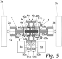
- Fig. 5 shows an electric drive axle 10 for a two-track motor vehicle in a second embodiment variant of the invention.
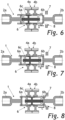
- the Fig. 6 to Fig. 9 show different switching positions A, B, C, D of this second embodiment variant, whereby the Fig. 6 to 8 with the switching positions A, B, C essentially Fig. 2 to Fig. 4 are equivalent to.
- the second embodiment variant differs from the first embodiment variant in that a further - fourth - switching position D is provided, in which the two half-shafts 2a, 2b are connected to one another in a rotationally fixed manner and the half-shafts 2a, 2b are also connected to a housing 7, so that they cannot rotate (see Fig. 9 ).
- the fourth switching position D thus forms a structurally simple parking lock 8 for the electric drive axle 1, which only has a few parts.
- Fig. 10 shows an electric drive axle 10 for a two-lane motor vehicle in a third embodiment variant of the invention, in which a parking lock 8 is also provided.
- the parking lock 8 is formed here by an additional ratchet wheel 8a arranged on the drive shaft 50b between the electric machine 5b and the gear stage 51, into which a locking member 8b, mounted fixed to the housing and actuated by an actuator (not shown), engages in a form-fitting manner and this drive shaft 50b is thus fixed to the housing , with simultaneous rotation-proof connection of the two half-shafts 2a, 2b in the switching position C.
- the parking lock 8 can also be arranged elsewhere in the drive path of the first electrical machine 5a or the second electrical machine 5b.
- a single switching element with three sliding sleeves 6a, 6b, 6c that are mechanically connected to one another - i.e. in the axial sliding direction - is required.
- the sliding sleeves 6a, 6b, 6c are in axial sliding direction connected to each other, but rotatable against each other.
- the third sliding sleeve 6c is designed to be rotatable relative to the first sliding sleeve 6a and the second sliding sleeve 6b.
- the switching element 6 not only the electrical machines 5a, 5b but also the driven wheels 4a, 4b and the gear stages can be selectively decoupled or coupled from the half shafts 2a, 2b. This function is particularly useful in off-road vehicles to ensure sufficient traction in difficult terrain or on surfaces with very different coefficients of friction.
Landscapes
- Engineering & Computer Science (AREA)
- Mechanical Engineering (AREA)
- Chemical & Material Sciences (AREA)
- Combustion & Propulsion (AREA)
- Transportation (AREA)
- General Engineering & Computer Science (AREA)
- Connection Of Motors, Electrical Generators, Mechanical Devices, And The Like (AREA)
- Arrangement And Mounting Of Devices That Control Transmission Of Motive Force (AREA)
Abstract
Die Erfindung betrifft eine elektrische Antriebsachse (1) für ein zweispuriges Kraftfahrzeug, mit einer ersten Halbwelle (2a) zum Antrieb eines ersten Rades (3a) und einer zweiten Halbwelle (2b) zum Antrieb eines zweiten Rades (3b) des Kraftfahrzeuges, wobei die erste Halbwelle (2a) über ein erstes Abtriebsrad (4a) durch eine erste elektrische Maschine (5a) und die zweite Halbwelle (2b) über ein zweites Abtriebsrad (4b) durch eine zweite elektrische Maschine (5b) antreibbar ist, wobei zumindest eine elektrische Maschine (5a, 5b) über ein Schaltelement (6) mit einem Rad (3a, 3b) antriebsverbindbar ist, wobei das Schaltelement (6) zumindest eine in einem ersten Antriebspfad zwischen dem ersten Abtriebsrad (4a) und der ersten Halbwelle (2a) koaxial zur ersten Halbwelle (2a) angeordnete und axial verschiebbare erste Schiebemuffe (6a) und zumindest eine in einem zweiten Antriebspfad zwischen dem zweiten Abtriebsrad (4b) und der zweiten Halbwelle (2b) koaxial zur zweiten Halbwelle (2b) angeordnete und axial verschiebbare zweite Schiebemuffe (6b) aufweist.Ein hoher Antriebswirkungsgrad kann erzielt werden, wenn die erste Schiebemuffe (6a) und die zweite Schiebemuffe (6b) über ein Verbindungselement (62c) fest miteinander verbunden sind.The invention relates to an electric drive axle (1) for a two-track motor vehicle, with a first half-shaft (2a) for driving a first wheel (3a) and a second half-shaft (2b) for driving a second wheel (3b) of the motor vehicle, the first Half shaft (2a) can be driven via a first driven gear (4a) by a first electrical machine (5a) and the second half shaft (2b) can be driven via a second driven gear (4b) by a second electrical machine (5b), wherein at least one electrical machine ( 5a, 5b) can be drive-connected to a wheel (3a, 3b) via a switching element (6), the switching element (6) being at least one in a first drive path between the first driven wheel (4a) and the first half shaft (2a) coaxially to the first Half shaft (2a) arranged and axially displaceable first sliding sleeve (6a) and at least one in a second drive path between the second driven gear (4b) and the second half shaft (2b) arranged coaxially to the second half shaft (2b) and axially displaceable second sliding sleeve (6b) A high drive efficiency can be achieved if the first sliding sleeve (6a) and the second sliding sleeve (6b) are firmly connected to one another via a connecting element (62c).
Description
Die Erfindung betrifft eine elektrische Antriebsachse für ein zweispuriges Kraftfahrzeug, mit einer ersten Halbwelle zum Antrieb eines ersten Rades und einer zweiten Halbwelle zum Antrieb eines zweiten Rades des Kraftfahrzeuges, wobei die erste Halbwelle über ein erstes Abtriebsrad durch eine erste elektrische Maschine und die zweite Halbwelle über ein zweites Abtriebsrad durch eine zweite elektrische Maschine antreibbar ist, wobei zumindest eine elektrische Maschine über ein Schaltelement mit einem Rad antriebsverbindbar ist, wobei das Schaltelement zumindest eine in einem ersten Antriebspfad zwischen dem ersten Abtriebsrad und der ersten Halbwelle koaxial zur ersten Halbwelle angeordnete und axial verschiebbare erste Schiebemuffe aufweist, welche ausgebildet ist, um in einer ersten Schaltstellung des Schaltelementes die erste Halbwelle vom ersten Abtriebsrad zu trennen und in einer zweiten Schaltstellung und/oder dritten Schaltstellung des Schaltelementes eine drehfeste Verbindung zwischen der ersten Halbwelle und dem ersten Abtriebsrad herzustellen, und wobei das Schaltelement zumindest eine in einem zweiten Antriebspfad zwischen dem zweiten Abtriebsrad und der zweiten Halbwelle koaxial zur zweiten Halbwelle angeordnete und axial verschiebbare zweite Schiebemuffe aufweist, welche ausgebildet ist, um in der ersten Schaltstellung des Schaltelementes die zweite Halbwelle vom zweiten Abtriebsrad zu trennen und in der zweiten Schaltstellung und/oder einer dritten Schaltstellung des Schaltelementes eine drehfeste Verbindung zwischen der zweiten Halbwelle und dem zweiten Abtriebsrad herzustellen.The invention relates to an electric drive axle for a two-track motor vehicle, with a first half-shaft for driving a first wheel and a second half-shaft for driving a second wheel of the motor vehicle, the first half-shaft being transmitted via a first driven wheel by a first electric machine and the second half-shaft via a second driven wheel can be driven by a second electric machine, wherein at least one electric machine can be driveably connected to a wheel via a switching element, the switching element being at least one which is arranged and axially displaceable in a first drive path between the first driven wheel and the first half-shaft coaxially with the first half-shaft has a first sliding sleeve, which is designed to separate the first half-shaft from the first driven gear in a first switching position of the switching element and to establish a rotationally fixed connection between the first half-shaft and the first driven gear in a second switching position and / or third switching position of the switching element, and where the switching element has at least one second sliding sleeve which is arranged coaxially to the second half shaft and is axially displaceable in a second drive path between the second driven gear and the second half shaft and which is designed to separate the second half shaft from the second driven gear in the first switching position of the switching element and in the second switching position and / or a third switching position of the switching element to establish a rotationally fixed connection between the second half shaft and the second driven gear.
Bekannt sind Anordnungen mit ein oder zwei Antriebsmaschinen. Anordnungen mit nur einer Antriebsmaschine verfügen über mechanisches Differentialgetriebe, um die Drehzahlunterschiede an den Rädern in Kurvenfahrt auszugleichen. Sofern kein mechanisches Torque-Vectoring-System vorgesehen ist, wird das Antriebsmoment immer 50:50 auf beide Räder aufgeteilt. Anordnungen mit zwei Antriebsmaschinen sind so ausgeführt, dass jeweils eine Maschine ein Rad antreibt. Der Vorteil dabei ist, dass hierbei kein Differentialgetriebe notwendig ist. Außerdem erlaubt es diese Anordnung, Torque-Vectoring rein durch regelungstechnische Maßnahmen darzustellen, was Fahrkomfort und -sicherheit wesentlich erhöht.Arrangements with one or two drive machines are known. Arrangements with only one drive machine have mechanical differential gears to compensate for the differences in speed at the wheels when cornering. Unless a mechanical torque vectoring system is provided, the drive torque is always split 50:50 between both wheels. Arrangements with two drive machines are designed so that one machine drives one wheel. The advantage is that no differential gear is necessary. This arrangement also allows torque vectoring to be represented purely through control measures, which significantly increases driving comfort and safety.
Elektrische Antriebsachsen werden mitunter als zusätzliche Antriebe genutzt. Wird eine Antriebsachse in gewissen Fahrsituationen nicht benötigt, kann es sinnvoll sein, den Antrieb mechanisch von den Rädern abzukoppeln, um ein dauerndes Mitschleppen zu verhindern, und somit den Antriebswirkungsgrad zu erhöhen. Die
Weiters ist aus der
Die
Die
Aufgabe der Erfindung ist eine elektrische Antriebsachse mit hohem Antriebswirkungsgrad bereitzustellen.The object of the invention is to provide an electric drive axle with high drive efficiency.
Diese Aufgabe wird erfindungsgemäß dadurch gelöst, dass die erste Schiebemuffe und die zweite Schiebemuffe über ein Verbindungselement fest miteinander verbunden sind.This object is achieved according to the invention in that the first sliding sleeve and the second sliding sleeve are firmly connected to one another via a connecting element.
In einer Ausführungsvariante der Erfindung ist vorgesehen, dass das Schaltelement zumindest eine in einem dritten Antriebspfad zwischen dem ersten Abtriebsrad und dem zweiten Abtriebsrad koaxial zur ersten und zweiten Halbwelle angeordnete und axial verschiebbare dritte Schiebemuffe aufweist, welche ausgebildet ist, um in der ersten und/oder zweiten Schaltstellung des Schaltelementes das erste Abtriebsrad und das zweite Abtriebsrad antriebsmäßig zu entkoppeln und in einer dritten Schaltstellung des Schaltelementes das erste und das zweite Abtriebsrad antriebsmäßig miteinander zu koppeln. In der dritten Schaltstellung kann somit eine vollständige Achssperre erzielt werden.In an embodiment variant of the invention it is provided that the switching element has at least one third sliding sleeve which is arranged in a third drive path between the first driven gear and the second driven gear coaxially to the first and second half shaft and is axially displaceable and which is designed to be in the first and/or In the second switching position of the switching element, the first driven gear and the second driven gear are drivingly decoupled and in a third switching position of the switching element, the first and second driven gears are drivingly coupled to one another. In the third switching position, a complete axle lock can be achieved.
Um ein gleichzeitiges Schalten der ersten Schiebemuffe und der zweiten Schiebemuffe zu ermöglichen, ist es vorteilhaft, wenn das Verbindungselement durch die dritte Schiebemuffe gebildet ist.In order to enable simultaneous switching of the first sliding sleeve and the second sliding sleeve, it is advantageous if the connecting element is formed by the third sliding sleeve.
Bevorzugt ist das erste Abtriebsrad und/oder das zweite Abtriebsrad durch ein Zahnrad einer Getriebestufe gebildet.Preferably, the first driven gear and/or the second driven gear is formed by a gear of a gear stage.
Günstigerweise ist die erste elektrische Maschine permanent mit dem ersten Abtriebsrad und/oder die zweite elektrische Maschine permanent mit dem zweiten Abtriebsrad antriebsverbunden. Die erste elektrische Maschine wirkt dabei direkt oder indirekt permanent - also ohne dazwischenliegendem Schaltelement auf das erste Abtriebsrad und die zweite elektrische Maschine direkt oder indirekt permanent auf das zweite Abtriebsrad ein.Advantageously, the first electrical machine is permanently connected to the first driven gear and/or the second electrical machine is permanently drive-connected to the second driven gear. The first electric machine acts directly or indirectly permanently - i.e. without an intermediate switching element - on the first driven wheel and the second electric machine directly or indirectly permanently acts on the second driven wheel.
Vorzugsweise sind die Schiebemuffen relativ zu den beiden Halbwellen und den beiden Abtriebsrädern axial verschiebbar gelagert.Preferably, the sliding sleeves are mounted so that they can move axially relative to the two half shafts and the two driven wheels.
Eine Ausführungsvariante der Erfindung sieht vor, dass die erste Schiebemuffe in jeder der Schaltstellungen permanent drehfest mit der ersten Halbwelle und die zweite Schiebemuffe in jeder der Schaltstellungen permanent drehfest mit dem zweiten Abtriebsrad verbunden sind.An embodiment variant of the invention provides that the first sliding sleeve is permanently connected in a rotationally fixed manner to the first half shaft in each of the switching positions and the second sliding sleeve is permanently connected in a rotationally fixed manner to the second driven wheel in each of the switching positions.
Vorzugsweise ist vorgesehen, dass in der ersten Schaltstellung die erste Schiebemuffe von dem ersten Abtriebsrad und die zweite Schiebemuffe von der zweiten Halbwelle getrennt sind.It is preferably provided that in the first switching position the first sliding sleeve is separated from the first driven wheel and the second sliding sleeve is separated from the second half shaft.
In weiterer Ausführung der Erfindung ist vorgesehen, dass in der zweiten und/oder dritten Schaltstellung die erste Schiebemuffe sowohl mit der ersten Halbwelle als auch mit dem ersten Abtriebsrad antriebsverbunden ist und die zweite Schiebemuffe sowohl mit der zweiten Halbwelle, als auch mit dem zweiten Abtriebsrad antriebsverbunden ist.In a further embodiment of the invention it is provided that in the second and/or third switching position the first sliding sleeve is drive-connected to both the first half-shaft and the first driven wheel, and the second sliding sleeve is drive-connected to both the second half-shaft and the second driven wheel is.
Besonders vorteilhaft ist es, wenn in der dritten Schaltstellung das erste Abtriebsrad und das zweite Abtriebsrad, vorzugsweise durch die dritte Schiebemuffe, miteinander gekoppelt sind. Auf diese Weise lässt sich ein starrer Antrieb auf die Abtriebsräder realisieren, um beispielsweise auf rutschigem Untergrund die Traktion zu erhöhen.It is particularly advantageous if, in the third switching position, the first driven gear and the second driven gear are coupled to one another, preferably by the third sliding sleeve. In this way, a rigid drive can be implemented on the driven wheels, for example to increase traction on slippery surfaces.
In einer Ausführungsvariante der Erfindung ist vorgesehen, dass in der dritten Schaltstellung zumindest ein Abtriebsrad über eine Parksperre blockierbar ist, wobei die Parksperre zumindest ein vorzugsweise auf einer Antriebswelle einer elektrischen Maschine angeordnetes Sperrrad aufweist, in welches ein gehäusefest gelagertes Sperrglied formschlüssig einlenkbar ist.In an embodiment variant of the invention it is provided that in the third switching position at least one driven wheel can be blocked via a parking lock, the parking lock having at least one locking wheel, preferably arranged on a drive shaft of an electric machine, into which a locking member mounted fixed to the housing can be positively deflected.
Eine weitere Ausführungsvariante der Erfindung sieht vor, dass in einer vierten Schaltstellung die erste Schiebemuffe sowohl mit der ersten Halbwelle, als auch mit dem ersten Abtriebsrad antriebsverbunden ist und die zweite Schiebemuffe sowohl mit der zweiten Halbwelle, als auch mit dem zweiten Abtriebsrad antriebsverbunden ist, wobei das erste Abtriebsrad und das zweite Abtriebsrad, vorzugsweise durch die dritte Schiebemuffe, miteinander gekoppelt sind, und dass das erste Schaltelement und/oder das zweite Schaltelement drehfest mit einem Gehäuse verbunden sind. Dies ermöglicht auf einfache Weise eine Parksperre mit einer minimalen Anzahl an Teilen.A further embodiment variant of the invention provides that in a fourth switching position, the first sliding sleeve is drive-connected to both the first half-shaft and the first driven wheel, and the second sliding sleeve is drive-connected to both the second half-shaft and the second driven wheel, whereby the first driven gear and the second driven gear are coupled to one another, preferably by the third sliding sleeve, and that the first switching element and / or the second switching element are connected to a housing in a rotationally fixed manner. This makes it easy to create a parking lock with a minimal number of parts.
Die beschrieben Antriebsachse ermöglicht einen hohen Wirkungsrad und eine sehr kompakte Bauweise.The drive axle described enables high efficiency and a very compact design.
Die Erfindung wird im Folgend anhand des in den nicht einschränkenden Figuren gezeigten Ausführungsbeispiels näher erläutert. Darin zeigen schematisch:
- Fig. 1
- eine erfindungsgemäße Antriebsachse in einer ersten Ausführungsvariante;
- Fig. 2
- diese Antriebsachse in einer ersten Schaltstellung;
- Fig. 3
- diese Antriebsachse in einer zweiten Schaltstellung;
- Fig. 4
- diese Antriebsachse in einer dritten Schaltstellung;
- Fig. 5
- eine erfindungsgemäße Antriebsachse in einer zweiten Ausführungsvariante;
- Fig. 6
- diese Antriebsachse in einer ersten Schaltstellung;
- Fig. 7
- diese Antriebsachse in einer zweiten Schaltstellung;
- Fig. 8
- diese Antriebsachse in einer dritten Schaltstellung;
- Fig. 9
- diese Antriebsachse in einer vierten Schaltstellung; und
- Fig. 10
- eine erfindungsgemäße Antriebsachse in einer dritten Ausführungsvariante.
- Fig. 1
- a drive axle according to the invention in a first embodiment variant;
- Fig. 2
- this drive axle in a first switching position;
- Fig. 3
- this drive axle in a second switching position;
- Fig. 4
- this drive axle in a third switching position;
- Fig. 5
- a drive axle according to the invention in a second embodiment variant;
- Fig. 6
- this drive axle in a first switching position;
- Fig. 7
- this drive axle in a second switching position;
- Fig. 8
- this drive axle in a third switching position;
- Fig. 9
- this drive axle in a fourth switching position; and
- Fig. 10
- a drive axle according to the invention in a third embodiment variant.
Die elektrischen Maschinen 5a, 5b können direkt oder indirekt über jeweils eine Antriebswelle 50a, 50b, zumindest eine Getriebestufe 51a, 51b und ein Zahnrad 52a, 52b auf das Abtriebsrad 4a, 4b einwirken. In gezeigten Ausführungsbeispiel der Erfindung werden das erste Abtriebsrad 4a und das zweite Abtriebsrad 4b jeweils durch ein Zahnrad 52a, 52b einer Getriebestufe 51a, 51b gebildet.The
Das Schaltelement 6 weist eine in einem ersten Antriebspfad zwischen dem ersten Abtriebsrad 4a und der ersten Halbwelle 2a koaxial zur ersten Halbwelle 2a angeordnete und axial verschiebbare erste Schiebemuffe 6a auf. Die erste Schiebemuffe 6a ist ausgebildet, um in einer ersten Schaltstellung des Schaltelementes 6 die erste Halbwelle 2a vom ersten Abtriebsrad 4a zu trennen und in einer zweiten Schaltstellung eine drehfeste Verbindung zwischen der ersten Halbwelle 2a und dem ersten Abtriebsrad 4a herzustellen.The switching
Das Schaltelement 6 weist weiters eine in einem zweiten Antriebspfad zwischen dem zweiten Abtriebsrad 4b und der zweiten Halbwelle 2b koaxial zur zweiten Halbwelle 2b angeordnete und axial verschiebbare zweite Schiebemuffe 6b auf. Diese ist ausgebildet, um in der ersten Schaltstellung des Schaltelementes 6 die zweite Halbwelle 2b vom zweiten Abtriebsrad 4b zu trennen und in einer zweiten Schaltstellung eine drehfeste Verbindung zwischen der zweiten Halbwelle 2b und dem zweiten Abtriebsrad 4b herzustellen.The switching
Die erste Schiebemuffe 6a und die zweite Schiebemuffe 6b sind dabei über ein Verbindungselement 7 fest miteinander verbunden.The first sliding
Das Schaltelement 6 weist darüber hinaus eine in einem dritten Antriebspfad zwischen dem ersten Abtriebsrad 4a und dem zweiten Abtriebsrad 4b koaxial zur ersten Halbwelle 2a und zweiten Halbwelle 2b angeordnete und axial verschiebbare dritte Schiebemuffe 6c auf. Die dritte Schiebemuffe 6c ist ausgebildet, um in der ersten und/oder zweiten Schaltstellung des Schaltelementes 6 das erste Abtriebsrad 4a und das zweite Abtriebsrad 4b antriebsmäßig zu entkoppeln und in einer dritten Schaltstellung des Schaltelementes 6 das erste Abtriebsrad 4a und das zweite Abtriebsrad 4b antriebsmäßig miteinander zu verbinden. Die dritte Schiebemuffe 6c bildet das Verbindungselement 62c zur Verbindung der ersten Schiebemuffe 6a und der zweiten Schiebemuffe 6b.The switching
Die zwei Abtriebsräder 4a und 4b sind als Zahnräder ausgeführt und jeweils über ein Getriebe (nicht dargestellt) mit den elektrischen Maschinen verbunden. Die zwei Halbwellen 2a und 2b treiben jeweils ein erstes, beispielsweise linkes Rad 3a bzw. zweites, beispielsweise rechtes Rad 3b des Fahrzeuges an. Die ersten 6a und zweiten Schiebemuffen 6b sind so ausgeführt, dass sie das erste Abtriebsrad 4a mit der ersten Halbwelle 2a bzw. das zweite Abtriebsrad 4b mit der zweiten Halbwelle 2b wahlweise drehfest verbinden oder entkoppeln. Die dritte Schiebemuffe 6c ist so ausgeführt, dass sie die beiden Abtriebsräder 4a und 4b wahlweise drehfest verbindet oder entkoppelt. Weiters sind die Schiebemuffen 6a, 6b und 6c so ausgeführt, dass sie sich zueinander verdrehen und nur gemeinsam axial verschieben lassen.The two driven
Das Schaltelement weist drei Schaltstellungen A, B, C auf, wobei die Schalstellungen durch unterschiedliche axiale Positionen der miteinander verbundenen Schiebermuffen 6a, 6b, 6c relativ zu den Halbwellen 2a, 2b und den Abtriebsrädern 4a, 4b charakterisiert sind. Die erste Schaltstellung A und die dritte Schaltstellung C bilden dabei Endstellungen des Schaltelementes 6 und die zweite Schaltstellung B eine zwischen der ersten A und der dritten Stellung C angeordnete Mittelstellung aus.The switching element has three switching positions A, B, C, the switching positions being characterized by different axial positions of the
Die beiden Halbwellen 2a, 2b weisen am den Abtriebsrädern 4a, 4b zugewandten Ende einen außenverzahnten Abschnitt 20a, 20b auf. Der außenverzahnte Abschnitt 20a der ersten Halbwelle 2a steht permanent - also in allen Schalstellungen A. B, C - mit einem innenverzahnten Bereich 60a der ersten Schiebemuffe 6a im Zahneingriff, wobei die erste Schiebemuffe 6a in Bezug auf die erste Halbwelle 2a verschiebbar ist. Weiters steht der außenverzahnte Abschnitt 20b der zweiten Halbwelle 2b mit einem innenverzahnten Bereich 60b der zweiten Schiebemuffe 6b in der zweiten Schaltstellung B und in der dritten Schaltstellung C im Zahneingriff. Die zweite Schiebemuffe 6b ist in Bezug auf die zweite Halbwelle 2b axial verschiebbar ausgebildet. In der ersten Schalstellung A stehen dagegen der außenverzahnte Abschnitt 20b der zweiten Halbwelle 2b und der innenverzahnte Bereich 60b der zweiten Schiebemuffe 6b nicht im Zahneingriff, sind also voneinander getrennt.The two half-
An dem den Halbwellen 2a, 2b abgewandten Ende weisen die erste Schaltmuffe 6a und die zweite Schaltmuffe 6b jeweils einen außenverzahnten Bereich 61a, 61b auf, der mit einer Außenverzahnung 40a, 40b des ersten Abtriebsrades 4a bzw. zweiten Abtriebsrades 4b korrespondiert. Die erste Schiebemuffe 6a ist relativ zum ersten Abtriebsrad 4a und die zweite Schiebemuffe 6b relativ zum zweiten Abtriebsrad 4b verschiebbar. In der ersten Schaltstellung A stehen dabei der außenverzahnte Bereich 61a der ersten Schaltmuffe 6a und die Außenverzahnung 40a des ersten Abtriebsrades 4a nicht im Zahneingriff, sind somit voneinander getrennt. In der zweiten Schaltstellung B und in der dritten Schaltstellung C stehen der außenverzahnte Bereich 61a der ersten Schaltmuffe 6a und die Außenverzahnung 40a des ersten Abtriebsrades im Zahneingriff, sind somit miteinander antriebsverbunden.At the end facing away from the
Die dritte Schiebemuffe 6c ist mittig und achsgleich zwischen der ersten Schiebemuffe 6c und der zweiten Schiebemuffe 6b angeordnet und weist einen Verbindungselement 62c auf, welcher die erste Schiebemuffe 6a und die zweite Schiebemuffe 6b miteinander verbindet. In axialer Verschieberichtung ist die dritte Schiebemuffe 6c fest - also relativ zur ersten Schaltmuffe 6a und zweiten Schaltmuffe 6b unverschieblich - mit der ersten 6a und der zweiten Schiebemuffe 6b verbunden, so dass alle drei Schiebemuffen 6a, 6b, 6c gemeinsam axial zwischen der ersten Schaltstellung A, der mittigen zweiten Schalt6stellung und der dritten Schaltstellung C verschoben werden können. Die dritte Schaltmuffe 6c ist aber an ihrem ersten Ende 60c ihres Verbindungselement 62c drehbar mit der ersten Schaltmuffe 6a und an ihrem zweiten Ende 61c des Wellenteils 62c drehbar mit der zweiten Schaltmuffe 6b verbunden, so dass die Schaltmuffen 6a, 6b, 6c relativ zueinander um die Drehachse 1a der Antriebsachse 1 verdreht werden können. Die dritte Schaltmuffe 6c weist einen mit dem Verbindungselement 62c drehfest verbundenen außenverzahnten Zahnradteil 63c auf, welcher permanent, also n jeder der drei Schaltstellungen A. B, C mit dem ersten Abtriebsrad 4a im Zahneingriff steht. In der ersten Schaltstellung A und der zweiten Schaltstellung B ist der Zahnradteil 63c vom zweiten Abtriebsrad 4b getrennt, steht in der dritten Schaltstellung C aber mit dem zweiten Abtriebsrad 4b und mit dem ersten Abtriebsrad 4a gleichzeitig im Zahneingriff. In der dritten Schaltstellung C sind somit das erste Abtriebsrad 4a und das zweite Abtriebsrad 4b antriebsmäßig gekoppelt, also drehfest miteinander verbunden.The third sliding
Die Schiebemuffen 6a, 6b, 6c sind so angeordnet und ausgeführt, dass
- in einer ersten Schaltstellung A sowohl
die Halbwellen 2a und 2bvon den Abtriebsrädern 4a und 4b, als auch dieAbtriebsräder 4a und 4b voneinander entkoppelt sind (Fig. 2 ), - in einer zweiten Schaltstellung B die erste Halbwelle 2a mit
dem ersten Abtriebsrad 4a und diezweite Halbwelle 2b mit dem zweiten Abtriebsrad 4b drehfest verbunden ist, diebeiden Abtriebsräder 4a und 4b aber voneinander entkoppelt sind (Fig. 3 ) und - in einer dritten Schalstellung 3 sowohl die
Halbwellen 2a und 2bmit den Abtriebsrädern 4a und 4b, als auch diebeiden Abtriebsräder 4a und 4b miteinander drehfest verbunden sind (Fig. 4 ).
- In a first switching position A, both the
half shafts wheels wheels Fig. 2 ), - in a second switching position B, the first half-
shaft 2a is connected in a rotationally fixed manner to the first drivengear 4a and the second half-shaft 2b to the second drivengear 4b, but the two drivengears Fig. 3 ) and - In a third switching position 3, both the
half shafts wheels wheels Fig. 4 ).
Die zweite Ausführungsvariante unterscheidet sich von der ersten Ausführungsvariante dadurch, dass eine weitere - vierte - Schaltstellung D vorgesehen ist, in der die beiden Halbwellen 2a, 2b drehfest miteinander verbunden sind und zudem die Halbwellen 2a, 2b mit einem Gehäuse 7 verbunden sind, sodass sie sich nicht drehen können (siehe
In allen Ausführungsvarianten ist nur ein einziges Schaltelement mit drei miteinander mechanisch -also in axialer Schieberichtung miteinander verbundenen Schiebemuffen 6a, 6b, 6c erforderlich. Die Schiebemuffen 6a, 6b, 6c sind zwar in axialer Schieberichtung miteinander verbunden, allerdings gegeneinander verdrehbar. Insbesondere ist die dritte Schiebemuffe 6c relativ zur ersten Schiebemuffe 6a und zur zweiten Schiebemuffe 6b verdrehbar ausgebildet.In all variants, only a single switching element with three sliding
Mit dem Schaltelement 6 können nicht nur die die elektrischen Maschinen 5a, 5b sondern auch die Abtriebsräder 4a, 4b und die Getriebestufen von den Halbwellen 2a, 2b wahlweise entkoppelt oder gekoppelt werden. Diese Funktion ist vor allem in geländegängigen Fahrzeugen sinnvoll, um in schwierigem Gelände oder auf Untergründen mit stark unterschiedlichen Reibkoeffizienten ausreichend Traktion sicher zu stellen.With the switching
Claims (12)
Applications Claiming Priority (1)
| Application Number | Priority Date | Filing Date | Title |
|---|---|---|---|
| ATA50253/2022A AT525812B1 (en) | 2022-04-19 | 2022-04-19 | ELECTRIC DRIVE AXLE |
Publications (2)
| Publication Number | Publication Date |
|---|---|
| EP4265459A1 true EP4265459A1 (en) | 2023-10-25 |
| EP4265459B1 EP4265459B1 (en) | 2024-05-01 |
Family
ID=86052434
Family Applications (1)
| Application Number | Title | Priority Date | Filing Date |
|---|---|---|---|
| EP23168181.8A Active EP4265459B1 (en) | 2022-04-19 | 2023-04-17 | Electric drive axle |
Country Status (2)
| Country | Link |
|---|---|
| EP (1) | EP4265459B1 (en) |
| AT (1) | AT525812B1 (en) |
Citations (8)
| Publication number | Priority date | Publication date | Assignee | Title |
|---|---|---|---|---|
| JP2018001845A (en) | 2016-06-29 | 2018-01-11 | 矢野 隆志 | Power system for performing speed control and torque vectoring control for electric vehicle |
| WO2018059783A1 (en) | 2016-09-28 | 2018-04-05 | Audi Ag | Drive device for a vehicle axle, in particular a rear axle |
| CN108819690A (en) | 2018-06-29 | 2018-11-16 | 北京新能源汽车股份有限公司 | Vehicle |
| CN109017251A (en) | 2018-06-29 | 2018-12-18 | 北京新能源汽车股份有限公司 | Vehicle |
| JP2019206204A (en) | 2018-05-28 | 2019-12-05 | 矢野 隆志 | Power system for executing torque vectoring control, variable rating output control, and shift control for electric vehicle |
| US20200238807A1 (en) * | 2017-07-27 | 2020-07-30 | Jing-Jin Electric Technologies Co., Ltd. | Vehicle two-power-source dual driving assembly |
| CN112406497A (en) | 2020-11-19 | 2021-02-26 | 北京汽车股份有限公司 | Dual-motor torque vector control system and method, power assembly and vehicle |
| EP3951211A1 (en) * | 2019-03-28 | 2022-02-09 | Mitsubishi Jidosha Kogyo Kabushiki Kaisha | Left-right wheel drive device |
-
2022
- 2022-04-19 AT ATA50253/2022A patent/AT525812B1/en active
-
2023
- 2023-04-17 EP EP23168181.8A patent/EP4265459B1/en active Active
Patent Citations (8)
| Publication number | Priority date | Publication date | Assignee | Title |
|---|---|---|---|---|
| JP2018001845A (en) | 2016-06-29 | 2018-01-11 | 矢野 隆志 | Power system for performing speed control and torque vectoring control for electric vehicle |
| WO2018059783A1 (en) | 2016-09-28 | 2018-04-05 | Audi Ag | Drive device for a vehicle axle, in particular a rear axle |
| US20200238807A1 (en) * | 2017-07-27 | 2020-07-30 | Jing-Jin Electric Technologies Co., Ltd. | Vehicle two-power-source dual driving assembly |
| JP2019206204A (en) | 2018-05-28 | 2019-12-05 | 矢野 隆志 | Power system for executing torque vectoring control, variable rating output control, and shift control for electric vehicle |
| CN108819690A (en) | 2018-06-29 | 2018-11-16 | 北京新能源汽车股份有限公司 | Vehicle |
| CN109017251A (en) | 2018-06-29 | 2018-12-18 | 北京新能源汽车股份有限公司 | Vehicle |
| EP3951211A1 (en) * | 2019-03-28 | 2022-02-09 | Mitsubishi Jidosha Kogyo Kabushiki Kaisha | Left-right wheel drive device |
| CN112406497A (en) | 2020-11-19 | 2021-02-26 | 北京汽车股份有限公司 | Dual-motor torque vector control system and method, power assembly and vehicle |
Also Published As
| Publication number | Publication date |
|---|---|
| AT525812A4 (en) | 2023-08-15 |
| AT525812B1 (en) | 2023-08-15 |
| EP4265459B1 (en) | 2024-05-01 |
Similar Documents
| Publication | Publication Date | Title |
|---|---|---|
| EP3873756B1 (en) | Electric drive axle of a vehicle | |
| WO2013083220A1 (en) | Drive train of a purely electrically all-wheel drivable motor vehicle | |
| WO2019020280A1 (en) | Axle drive | |
| DE19721091A1 (en) | Two-position drive disconnection unit for differential of motor vehicle | |
| DE102019107538A1 (en) | Torque vectoring transmission for a motor vehicle | |
| DE102016213233B4 (en) | Differential gear with shutdown function and locking function | |
| EP1254326B1 (en) | Differential gearbox with locking coupling and distributor gearbox for motor vehicles equipped therewith | |
| WO2017194322A1 (en) | Transmission for a tunnel boring machine with a planetary stage which is selectively engageable | |
| EP4265459B1 (en) | Electric drive axle | |
| WO2023187209A1 (en) | Improved switching of axial couplings with flat teeth under load | |
| DE102009027342A1 (en) | Superposition gear for a steering system | |
| DE102020117269B3 (en) | Gear arrangement | |
| EP1199237B1 (en) | Transmission for a rail vehicle | |
| DE102021109712A1 (en) | Switching unit and drive unit for an electrified drive train of a motor vehicle and axle module | |
| DE102020112624A1 (en) | Transmission device for an electric drive of a vehicle | |
| DE102021100448B3 (en) | Locking differential gear for a motor vehicle and method for operating a locking differential gear for a motor vehicle | |
| DE102018003897A1 (en) | Electric drive for a motor vehicle, in particular for a motor vehicle | |
| DE102022207819B4 (en) | Differential device with side shaft activation and switchable locking function | |
| DE102022111557B4 (en) | Parking lock device for an electric drive axle and electric drive axle with a parking lock device | |
| WO2018133998A1 (en) | Transmission arrangement for the controllable distribution of a drive torque from an input element to at least one output element in an all-wheel drive train of an all-wheel drive motor vehicle | |
| WO2018086798A1 (en) | Transmission assembly for a vehicle, and vehicle having the transmission assembly | |
| DE19942532B4 (en) | Gear and clutch for it | |
| WO2024008718A1 (en) | Electric drive assembly for a vehicle | |
| DE102022203304A1 (en) | Drive arrangement for a vehicle and electric axle with the drive arrangement | |
| DE102020125804A1 (en) | Driving device for a motor vehicle |
Legal Events
| Date | Code | Title | Description |
|---|---|---|---|
| PUAI | Public reference made under article 153(3) epc to a published international application that has entered the european phase |
Free format text: ORIGINAL CODE: 0009012 |
|
| STAA | Information on the status of an ep patent application or granted ep patent |
Free format text: STATUS: THE APPLICATION HAS BEEN PUBLISHED |
|
| AK | Designated contracting states |
Kind code of ref document: A1 Designated state(s): AL AT BE BG CH CY CZ DE DK EE ES FI FR GB GR HR HU IE IS IT LI LT LU LV MC ME MK MT NL NO PL PT RO RS SE SI SK SM TR |
|
| STAA | Information on the status of an ep patent application or granted ep patent |
Free format text: STATUS: REQUEST FOR EXAMINATION WAS MADE |
|
| 17P | Request for examination filed |
Effective date: 20231122 |
|
| RBV | Designated contracting states (corrected) |
Designated state(s): AL AT BE BG CH CY CZ DE DK EE ES FI FR GB GR HR HU IE IS IT LI LT LU LV MC ME MK MT NL NO PL PT RO RS SE SI SK SM TR |
|
| GRAP | Despatch of communication of intention to grant a patent |
Free format text: ORIGINAL CODE: EPIDOSNIGR1 |
|
| STAA | Information on the status of an ep patent application or granted ep patent |
Free format text: STATUS: GRANT OF PATENT IS INTENDED |
|
| INTG | Intention to grant announced |
Effective date: 20240131 |
|
| GRAS | Grant fee paid |
Free format text: ORIGINAL CODE: EPIDOSNIGR3 |
|
| GRAA | (expected) grant |
Free format text: ORIGINAL CODE: 0009210 |
|
| STAA | Information on the status of an ep patent application or granted ep patent |
Free format text: STATUS: THE PATENT HAS BEEN GRANTED |
|
| AK | Designated contracting states |
Kind code of ref document: B1 Designated state(s): AL AT BE BG CH CY CZ DE DK EE ES FI FR GB GR HR HU IE IS IT LI LT LU LV MC ME MK MT NL NO PL PT RO RS SE SI SK SM TR |
|
| REG | Reference to a national code |
Ref country code: GB Ref legal event code: FG4D Free format text: NOT ENGLISH |