EP4265209A1 - Schalteinheit zum betrieb eines multikathetersystems - Google Patents
Schalteinheit zum betrieb eines multikathetersystems Download PDFInfo
- Publication number
- EP4265209A1 EP4265209A1 EP23168182.6A EP23168182A EP4265209A1 EP 4265209 A1 EP4265209 A1 EP 4265209A1 EP 23168182 A EP23168182 A EP 23168182A EP 4265209 A1 EP4265209 A1 EP 4265209A1
- Authority
- EP
- European Patent Office
- Prior art keywords
- sockets
- catheters
- catheter
- signals
- console
- Prior art date
- Legal status (The legal status is an assumption and is not a legal conclusion. Google has not performed a legal analysis and makes no representation as to the accuracy of the status listed.)
- Pending
Links
- 238000000034 method Methods 0.000 claims description 34
- 108091006146 Channels Proteins 0.000 description 50
- 238000002679 ablation Methods 0.000 description 15
- 230000007831 electrophysiology Effects 0.000 description 9
- 238000002001 electrophysiology Methods 0.000 description 9
- 238000013507 mapping Methods 0.000 description 4
- 230000004044 response Effects 0.000 description 4
- 230000006870 function Effects 0.000 description 3
- 230000000747 cardiac effect Effects 0.000 description 2
- 230000007274 generation of a signal involved in cell-cell signaling Effects 0.000 description 2
- 238000003780 insertion Methods 0.000 description 2
- 230000037431 insertion Effects 0.000 description 2
- 230000003287 optical effect Effects 0.000 description 2
- 210000000056 organ Anatomy 0.000 description 2
- 238000012545 processing Methods 0.000 description 2
- 238000002059 diagnostic imaging Methods 0.000 description 1
- 238000004520 electroporation Methods 0.000 description 1
- 230000002708 enhancing effect Effects 0.000 description 1
- 230000002427 irreversible effect Effects 0.000 description 1
- 238000012986 modification Methods 0.000 description 1
- 230000004048 modification Effects 0.000 description 1
- 239000000523 sample Substances 0.000 description 1
- 230000008054 signal transmission Effects 0.000 description 1
- 230000001225 therapeutic effect Effects 0.000 description 1
- 238000012546 transfer Methods 0.000 description 1
- 210000005166 vasculature Anatomy 0.000 description 1
Images

Classifications
-
- A—HUMAN NECESSITIES
- A61—MEDICAL OR VETERINARY SCIENCE; HYGIENE
- A61B—DIAGNOSIS; SURGERY; IDENTIFICATION
- A61B18/00—Surgical instruments, devices or methods for transferring non-mechanical forms of energy to or from the body
- A61B18/04—Surgical instruments, devices or methods for transferring non-mechanical forms of energy to or from the body by heating
- A61B18/12—Surgical instruments, devices or methods for transferring non-mechanical forms of energy to or from the body by heating by passing a current through the tissue to be heated, e.g. high-frequency current
- A61B18/14—Probes or electrodes therefor
- A61B18/1492—Probes or electrodes therefor having a flexible, catheter-like structure, e.g. for heart ablation
-
- A—HUMAN NECESSITIES
- A61—MEDICAL OR VETERINARY SCIENCE; HYGIENE
- A61B—DIAGNOSIS; SURGERY; IDENTIFICATION
- A61B18/00—Surgical instruments, devices or methods for transferring non-mechanical forms of energy to or from the body
- A61B18/04—Surgical instruments, devices or methods for transferring non-mechanical forms of energy to or from the body by heating
- A61B18/12—Surgical instruments, devices or methods for transferring non-mechanical forms of energy to or from the body by heating by passing a current through the tissue to be heated, e.g. high-frequency current
- A61B18/1206—Generators therefor
-
- A—HUMAN NECESSITIES
- A61—MEDICAL OR VETERINARY SCIENCE; HYGIENE
- A61B—DIAGNOSIS; SURGERY; IDENTIFICATION
- A61B18/00—Surgical instruments, devices or methods for transferring non-mechanical forms of energy to or from the body
- A61B18/04—Surgical instruments, devices or methods for transferring non-mechanical forms of energy to or from the body by heating
- A61B18/12—Surgical instruments, devices or methods for transferring non-mechanical forms of energy to or from the body by heating by passing a current through the tissue to be heated, e.g. high-frequency current
- A61B18/14—Probes or electrodes therefor
-
- A—HUMAN NECESSITIES
- A61—MEDICAL OR VETERINARY SCIENCE; HYGIENE
- A61B—DIAGNOSIS; SURGERY; IDENTIFICATION
- A61B18/00—Surgical instruments, devices or methods for transferring non-mechanical forms of energy to or from the body
- A61B2018/00053—Mechanical features of the instrument of device
- A61B2018/00172—Connectors and adapters therefor
- A61B2018/00178—Electrical connectors
-
- A—HUMAN NECESSITIES
- A61—MEDICAL OR VETERINARY SCIENCE; HYGIENE
- A61B—DIAGNOSIS; SURGERY; IDENTIFICATION
- A61B18/00—Surgical instruments, devices or methods for transferring non-mechanical forms of energy to or from the body
- A61B2018/00315—Surgical instruments, devices or methods for transferring non-mechanical forms of energy to or from the body for treatment of particular body parts
- A61B2018/00345—Vascular system
- A61B2018/00351—Heart
-
- A—HUMAN NECESSITIES
- A61—MEDICAL OR VETERINARY SCIENCE; HYGIENE
- A61B—DIAGNOSIS; SURGERY; IDENTIFICATION
- A61B18/00—Surgical instruments, devices or methods for transferring non-mechanical forms of energy to or from the body
- A61B2018/00571—Surgical instruments, devices or methods for transferring non-mechanical forms of energy to or from the body for achieving a particular surgical effect
- A61B2018/00577—Ablation
-
- A—HUMAN NECESSITIES
- A61—MEDICAL OR VETERINARY SCIENCE; HYGIENE
- A61B—DIAGNOSIS; SURGERY; IDENTIFICATION
- A61B18/00—Surgical instruments, devices or methods for transferring non-mechanical forms of energy to or from the body
- A61B2018/00636—Sensing and controlling the application of energy
- A61B2018/0066—Sensing and controlling the application of energy without feedback, i.e. open loop control
-
- A—HUMAN NECESSITIES
- A61—MEDICAL OR VETERINARY SCIENCE; HYGIENE
- A61B—DIAGNOSIS; SURGERY; IDENTIFICATION
- A61B18/00—Surgical instruments, devices or methods for transferring non-mechanical forms of energy to or from the body
- A61B2018/00636—Sensing and controlling the application of energy
- A61B2018/00773—Sensed parameters
- A61B2018/00839—Bioelectrical parameters, e.g. ECG, EEG
-
- A—HUMAN NECESSITIES
- A61—MEDICAL OR VETERINARY SCIENCE; HYGIENE
- A61B—DIAGNOSIS; SURGERY; IDENTIFICATION
- A61B18/00—Surgical instruments, devices or methods for transferring non-mechanical forms of energy to or from the body
- A61B2018/0091—Handpieces of the surgical instrument or device
- A61B2018/00916—Handpieces of the surgical instrument or device with means for switching or controlling the main function of the instrument or device
-
- A—HUMAN NECESSITIES
- A61—MEDICAL OR VETERINARY SCIENCE; HYGIENE
- A61B—DIAGNOSIS; SURGERY; IDENTIFICATION
- A61B18/00—Surgical instruments, devices or methods for transferring non-mechanical forms of energy to or from the body
- A61B18/04—Surgical instruments, devices or methods for transferring non-mechanical forms of energy to or from the body by heating
- A61B18/12—Surgical instruments, devices or methods for transferring non-mechanical forms of energy to or from the body by heating by passing a current through the tissue to be heated, e.g. high-frequency current
- A61B18/1206—Generators therefor
- A61B2018/124—Generators therefor switching the output to different electrodes, e.g. sequentially
-
- A—HUMAN NECESSITIES
- A61—MEDICAL OR VETERINARY SCIENCE; HYGIENE
- A61B—DIAGNOSIS; SURGERY; IDENTIFICATION
- A61B2562/00—Details of sensors; Constructional details of sensor housings or probes; Accessories for sensors
- A61B2562/22—Arrangements of medical sensors with cables or leads; Connectors or couplings specifically adapted for medical sensors
- A61B2562/225—Connectors or couplings
Definitions
- the present disclosure relates generally to medical devices, and particularly to methods and systems for operating a medical system having multiple catheters.
- U.S. Patent Application Publication 2018/0168729 describes a catheter system for ablating a tissue portion of a body and visualizing the ablation in real time.
- An operating console of the EP system typically has a fixed number of sockets and channels available for the catheters. In some cases, there is a mismatch between the number of sockets and/or channels (i) required for the catheters and (ii) available in the console. In such cases, the user of the EP system may have to unplug a given catheters from the console, and subsequently, to re-plug the given catheter to the console, which is time consuming and interferes with the EP procedure.
- Examples of the present disclosure that are described hereafter provide improved techniques for operating a medical system having multiple catheters and managing all the channels without forcing the user to handle the unplugging and re-plugging of catheters during the procedure.
- a system having a plurality of multi-channel catheters comprises a switching unit, and circuitry.
- the switching unit comprises (i) first sockets, which are configured to connect between the switching unit and the channels of one or more catheters, and (ii) second sockets, which are configured to connect, via the switching unit, between the first sockets a console.
- the system comprises memory devices, such as electrically erasable programmable read-only memory (EEPROM) devices, each of which is coupled to a respective catheter of the multi-channel catheters.
- EEPROM electrically erasable programmable read-only memory
- the EEPROM is configured to store information about the channels of the respective catheter.
- the information may comprise, for example, properties of the signal, and the source and destination of the signal of each channel.
- the circuitry is configured, based on information received from the EEPROM devices of the one or more catheters, to produce a control signal for routing the signals.
- the circuitry is configured to provide instructions to the switching unit on how to route the signals for each channel of each catheter plugged into the first sockets.
- the switching unit comprises a switch, which is configured, based on the control signal received from the circuitry to route signals conducted in the channels between the first and second sockets, so that each signal is routed between the source and destination stored in the respective EEPROM device.
- the console comprises third sockets, so that the first, second, and third sockets comprise first, second and third interconnects, respectively, which are configured to conduct the signals.
- the number of the first interconnects may differ from the number of the second interconnects, and the number of the third interconnects is similar to the number of the second interconnects.
- the user of the system can plug any number of catheters into the first sockets of the switching unit, and the signals are automatically routed between the source and the destination.
- the circuitry when first and second catheters are plugged into the switching unit, the circuitry is configured to detect that the first catheter is active and the second catheter is inactive, and responsively, to produce the control signal that controls the switching unit to connect between the first catheter and the console, and to disconnect between the second catheter and the console. Moreover, the circuitry is configured to control the switching unit to carry out the connecting and disconnecting in a channel level. In other words, to connect active channels, and to temporary disconnect inactive channels. Note that whenever a given channel and/or a given catheter is active (e.g., intended to send and/or receive a signal), the circuitry is configured to re-connect the given channel and/or catheter.
- the disclosed techniques improve the versatility and ease-of-use of multi-catheter medical systems, and improve the robustness of signal transmission during medical procedures that require using a plurality of multi-channel catheters.
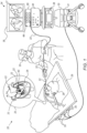
- Fig. 1 is a schematic, pictorial illustration of a catheter-based tracking and ablation system 20, in accordance with an example of the present disclosure.
- system 20 comprises a multi-catheter system configured to operate a plurality of one or more types of catheters.
- system 20 comprises multiple cardiac catheters 22, which are configured to carry out cardiac procedures, and a control console 24.
- catheters 22 may be used for any suitable therapeutic and/or diagnostic purposes, such as sensing electro-anatomical signals and/or ablation of tissue in a heart 26.
- console 24 comprises a processor 33, typically a general-purpose computer, with suitable front end and interface circuits for receiving signals via catheters 22 and for controlling the other components of system 20 described herein.
- Console 24 further comprises a user display 35, which is configured to receive from processor 33 graphical and/or textual display items, such as a map 27 of heart 26, and to display map 27.
- map 27 may comprise any suitable type of three-dimensional (3D) anatomical map produced using any suitable technique.
- the anatomical map may be produced using an anatomical image produced by using a suitable medical imaging system, or using a fast anatomical mapping (FAM) technique available in the CARTO TM system, produced by Biosense Webster Inc. (Irvine, Calif.), or using any other suitable technique, or using any suitable combination of the above.
- FAM fast anatomical mapping
- console 24 comprises a recording unit 38, which is configured to record in case of failure in the CARTO TM and/or a failure to pace in certain electrodes.
- a patient interface unit (PIU) 44 which is configured to produce a signal indicative of the location and electrocardiogram (ECG) signals that are acquired and processed.
- ECG electrocardiogram
- system 20 comprises a switching unit (SU) 55, which is connected to PIU 44 of console 24, and has one or more sockets 66 for connecting with catheters 22, respectively.
- SU switching unit
- PIU 44 of console 24 has one or more sockets 66 for connecting with catheters 22, respectively.
- only one catheter 22 is connected to a respective socket 66, for the sake of clarity.
- the proximal end of all catheters 22 are connected to respective sockets 66 of SU 55.
- SU 55 is configured to route signals between catheters 22 and console 24.
- the structure and functionality of SU 55 are described in detail in Fig. 2 below.
- the PIU and the switching unit may be integrated together, so that the user of system 20 is plugging (and unplugging) the catheters and other components to the integrated entity.
- a physician 30 inserts one or more catheters, such as catheter 22, through the vasculature system of a patient 28 lying on a table 29, so as to perform electro-anatomical (EA) mapping of tissue in question of heart 26.
- EA electro-anatomical
- catheter 22 comprises a distal-end assembly 40 having multiple sensing electrodes (not shown).
- distal-end assembly 40 may comprise: (i) a basket catheter having multiple splines, each spline having multiple sensing electrodes, (ii) a balloon catheter having multiple sensing electrodes disposed on the surface of the balloon, or (iii) a focal catheter having multiple sensing electrodes.
- Each sensing electrode is configured to produce, in response to sensing electrophysiological (EP) signals in tissue of heart 26, one or more signals indicative of the sensed EP signals.
- EP electrophysiological
- Fig. 1 three catheters 22 are inserted into heart 26, but in other examples, any other suitable number of catheters may be inserted into an organ in question.
- the catheterization procedure may require the insertion of between about 5 and 8 catheters.
- different type of catheters may be inserted and used at the same time, for example: a balloon or basket catheter (for performing sensing and/or ablation at multiple locations), together with a focal catheter (for sensing or ablating tissue at a single position).
- the proximal end of catheter 22 is connected, inter alia, to interface circuits (not shown) of PIU, or to SU 55 (as shown in the example of Fig. 1 ), so as to transfer these signals to processor 33 for performing the EA mapping.
- catheter 22 may comprise one or more ablation electrodes (not shown) coupled to distal-end assembly 40.
- the ablation electrodes are configured to ablate tissue at a target location of heart 26, which is determined based on the analysis of the EA mapping of the tissue in question of heart 26.
- physician 30 navigates distal-end assembly 40 in close proximity to the target location in heart 26 e.g., using a manipulator 32 for manipulating catheter 22.
- physician 30 places one or more of the ablation electrodes (of a selected catheter) in contact with the target tissue, and applies, to the tissue, one or more ablation signals.
- physician 30 may use any different sorts of suitable catheters for ablating tissue of heart 26 so as to carry out the aforementioned ablation plan.
- the position of distal-end assembly 40 in the heart cavity is measured using a position sensor (not shown) of a magnetic position tracking system.
- console 24 comprises a driver circuit 41, which is configured to drive magnetic field generators 36 placed at known positions external to patient 28 lying on table 29, e.g., below the patient's torso.
- the position sensor is coupled to the distal end, and is configured to generate position signals in response to sensed external magnetic fields from field generators 36.
- the position signals are indicative of the position the distal end of catheter 22 in the coordinate system of the position tracking system.
- This method of position sensing is implemented in various medical applications, for example, in the CARTO TM system, produced by Biosense Webster Inc. (Irvine, Calif.) and is described in detail in U.S. Patents 5,391,199 , 6, 690, 963 , 6,484,118 , 6, 239, 724 , 6, 618, 612 and 6, 332, 089 , in PCT Patent Publication WO 96/05768 , and in U.S. Patent Application Publications 2002/0065455 A1 , 2003/0120150 A1 and 2004/0068178 A1 , whose disclosures are all incorporated herein by reference.
- the coordinate system of the position tracking system is registered with the coordinate systems of system 20 and map 27, so that processor 33 is configured to display, the position of distal-end assembly 40, over the anatomical or EA map (e.g., map 27).
- processor 33 typically comprises a general-purpose computer, which is programmed in software to carry out the functions described herein.
- the software may be downloaded to the computer in electronic form, over a network, for example, or it may, alternatively or additionally, be provided and/or stored on non-transitory tangible media, such as magnetic, optical, or electronic memory.
- system 20 is shown by way of example, in order to illustrate certain problems that are addressed by examples of the present disclosure and to demonstrate the application of these examples in enhancing the performance of such a system.
- Examples of the present disclosure are by no means limited to this specific sort of example system, and the principles described herein may similarly be applied to other sorts of medical systems.
- Fig. 2 is a schematic, pictorial illustration of switching unit (SU) 55 connecting between catheters 22 and PIU 44 of console 24, in accordance with an example of the present disclosure.
- SU switching unit
- SU 55 comprises sockets 66a, 66b and 66c, which are configured to connect between SU 55 and channels of one or more catheters.
- three catheters, 22a, 22b and 22c are connected to SU 55 via sockets 66a, 66b and 66c, respectively.
- each socket 66 comprises about eight (8) channels 77, but in other examples, each socket 66 may have any suitable number of channels (e.g., socket 66a may have about eight channels 77, and socket 66b may have about twenty (20) channels 77).
- catheters 22a, 22b and 22c comprise suitable plug, which are configured to snugly fit into sockets 66a, 66b and 66c, respectively.
- Each socket and plug may have any suitable number of channels configured to exchange signals between catheters 22a, 22b and 22c and sockets 66a, 66b and 66c, respectively.
- SU 55 comprises sockets 99, which are configured to connect, via SU 55, between sockets 66 and PIU 44 of console 24.
- PIU 44 may be integrated with SU 55, so that sockets 99 are configured to connect between sockets 66 and console 24 directly.
- SU 55 comprises a socket 99a having about four (4) channels 77 and a socket 99b having about six (6) channels 77.
- PIU 44 of console 24 (or any other interface of console 24) has sockets 98a and 98b.
- sockets 99a and 98a have the same number of channels 77 (e.g., about 4 channels), and sockets 99b and 98b have the same number of channels 77 (e.g., about 6 channels).
- the connection between SU 55 and PIU 44 comprises one-to-one connection, which is enabled by the same number of channels.
- each pair of channels is interconnected using a cable 70.
- system 20 instead of a pair of sockets (e.g., sockets 99a and 98a) and cable 70, system 20 comprises a pair of plug and socket.
- a plug instead of socket 99a, which is configured to fit into socket 98a, or vice versa, so as to conduct signals in channels 77, between SU 55 and PIU 44.
- SU 55 may comprise respective plugs.
- at least one of catheters 22 (and/or cables 68) may have a socket and SU 55 may have a suitable plug for connecting between the respective catheter 22 and SU 55.
- each catheter 22 may have between about 3 and 500 channels 77.
- a focal catheter 22 may have about 3 channels 77 (e.g., for a position sensor, and one or two electrocardiogram (ECG) and/or temperature sensors), whereas a multi-electrode basket catheter 22 may have about 500 channels 77 (e.g., for position sensors, temperature sensors, ECG sensors, contact force sensors, and for ablation electrodes).
- ECG electrocardiogram
- a multi-electrode basket catheter 22 may have about 500 channels 77 (e.g., for position sensors, temperature sensors, ECG sensors, contact force sensors, and for ablation electrodes).
- At least one of, and typically each catheter 22, comprises a memory device.
- catheters 22a, 22b and 22c comprise electrically erasable programmable read-only memory (EEPROM) devices 42a, 42b and 42c, respectively.
- EEPROM device 42 of respective catheter 22 is configured to store information related to the respective catheter 22, such as but not limited to catheter identification, type of signals intended to be conducted in each channel of the catheter, and the destination of each signal).
- system 20 comprises circuitry 64, which is configured to receive from each EEPROM device 42, information about the number of channels 77, the type of signal, and the destination of each signal conducted in each respective channel 77.
- the information is received over cables 68 of catheters 22, and for each catheter 22 and respective socket 66, one of channels 77 may be allocated to the information received from the respective EEPROM device 42.
- circuitry 64 is configured, to receive the information from EEPROM devices 42a, 42b and 42c, of catheters 22a, 22b, and 22c, respectively. Based on information received from EEPROM devices 42, circuitry 64 is configured to produce a control signal for routing the signals between sockets 66 and 99, so as to route the signals between catheters 22 and console 24. In other words, circuitry 64 is configured to provide instructions to SU 55 on how to route the signals for each channel of each catheter plugged into sockets 66.
- SU 55 comprises a switch 88, which is configured, based on the control signal, to route the signals conducted in channels 77, between sockets 66 and 99.
- switch 88 comprises about three internal switches (ISs) 60, configured to perform the signal routing between each channel 77 and a respective channel 99.
- At least one of catheters 22 is active and at least one of catheters 22 (e.g., catheter 22c) is inactive.
- circuitry 64 based on the information received from EEPROM devices 42, circuitry 64 is configured to detect that catheter 22a is active and catheter 22c is inactive. In such examples, circuitry 64 is configured to produce the control signal that controls switch 88 of SU 55 to connect between the catheter 22a and console 24, and to disconnect between catheter 22c and console 24. Note that in response to receiving from EEPROM device 42c a signal indicative of catheter 22c being activated, circuitry 64 is configured to produce an additional control signal that controls switch 88 of SU 55 to reconnect between the catheter 22c and console 24.
- circuitry 64 typically comprises a general-purpose processing device, which is programmed in software to carry out the functions described herein.
- the software may be downloaded to the processing device in electronic form, over a network, for example, or it may, alternatively or additionally, be provided and/or stored on non-transitory tangible media, such as magnetic, optical, or electronic memory.
- Fig. 3 is a flow charts that schematically illustrate a method for operating system 20 using SU 55, in accordance with examples of the present disclosure.
- the method begins at a catheter insertion step 100, with physician 30 inserting multiple catheters 22 into patient organ (e.g., heart 26), and circuitry 64 receiving from EEPROM devices 42, signals and information about the respective catheters 22 and signals, as described in detail in Fig. 2 above.
- patient organ e.g., heart 26
- circuitry 64 receiving from EEPROM devices 42, signals and information about the respective catheters 22 and signals, as described in detail in Fig. 2 above.
- circuitry 64 produces one or more control signals for routing of the signals within SU 55 having: (i) sockets 66 for connecting between SU 55 and channels of catheters 22, and (ii) sockets 99 for connecting, via SU 55, between the sockets 66 and sockets 98 of PIU 44 of console 24.
- the control signal generation and the structure and functionality of SU 55 are described in detail in Fig. 2 above.
- control signals are applied to switch 88 for routing the signals conducted in channels 77, between the sockets 66 and 99.
- the control signals comprise routing instructions for each of the signals received from each channel of catheters 22.
- switch 88 is configured to route the respective signals (via the channels defined in the control signals) to the destination within console 24.
- signals from a position sensor are routed to a position tracking system or module
- ECG signals may be routed to processor 33
- ablation signals may be routed from a radiofrequency (RF) generator (not shown) that is implemented, e.g., in console 24, to ablation electrodes of a respective catheter 22.
- RF radiofrequency
- physician 30 plugs all catheters 22 into sockets 66 of SU 55 and SU 55 routes the channels from the different catheters 22 to PIU 44 or to other parts of system 20 as needed (e.g., an RF generator, or an irreversible electroporation (IRE) generator, or processor 33).
- PIU 44 e.g., an RF generator, or an irreversible electroporation (IRE) generator, or processor 33.
- IRE irreversible electroporation
- circuitry 64 in response to detecting that catheter 22a is active and catheter 22c is inactive, is configured to produce the control signal that controls switch 88 of SU 55 to connect between catheter 22a and console 24, and to disconnect between catheter 22c and console 24, as described in Fig. 2 above.
- the methods and systems described herein can also be used in other applications, such as in any catheterization procedure using multiple catheters or probes having multiple signals intended to be routed between the catheters and other parts of the respective medical system.
- Example 1 The system according to Example 1, wherein the console includes third sockets, wherein the first, second, and third sockets include first, second and third interconnects, respectively, which are configured to conduct the signals, and wherein the first sockets include a first number of the first interconnects, different from a second number of the second interconnects.
- Example 1 The system according to Example 1, wherein at least one of the catheters includes a memory device, which is configured to store the information.
- Example 4 The system according to Example 4, wherein the memory device includes an electrically erasable programmable read-only memory (EEPROM).
- EEPROM electrically erasable programmable read-only memory
- the catheters include first and second catheters
- the circuitry is configured to: (i) detect that the first catheter is active and the second catheter is inactive, and (ii) produce the control signal that controls the switching unit to connect between the first catheter and the console, and to disconnect between the second catheter and the console.
- a method including:
- Example 7 The method according to Example 7, wherein the console includes third sockets, wherein the first, second, and third sockets include first, second and third interconnects, respectively, for conducting the signals, and wherein the first sockets include a first number of the first interconnects, different from a second number of the second interconnects.
- Example 7 The method according to Example 7, wherein at least one of the catheters includes a memory device for storing the information, and wherein the information is received from the memory device.
- Example 10 The method according to Example 10, wherein the memory device includes an electrically erasable programmable read-only memory (EEPROM).
- EEPROM electrically erasable programmable read-only memory
- the catheters include first and second catheters, wherein, receiving the information includes detecting that the first catheter is active and the second catheter is inactive, and producing the control signal includes controlling the switching unit to connect between the first catheter and the console, and to disconnect between the second catheter and the console.
Applications Claiming Priority (1)
| Application Number | Priority Date | Filing Date | Title |
|---|---|---|---|
| US17/722,664 US20230329779A1 (en) | 2022-04-18 | 2022-04-18 | Switching unit for operating a multi-catheter system |
Publications (1)
| Publication Number | Publication Date |
|---|---|
| EP4265209A1 true EP4265209A1 (de) | 2023-10-25 |
Family
ID=86052128
Family Applications (1)
| Application Number | Title | Priority Date | Filing Date |
|---|---|---|---|
| EP23168182.6A Pending EP4265209A1 (de) | 2022-04-18 | 2023-04-17 | Schalteinheit zum betrieb eines multikathetersystems |
Country Status (4)
| Country | Link |
|---|---|
| US (1) | US20230329779A1 (de) |
| EP (1) | EP4265209A1 (de) |
| JP (1) | JP2023158655A (de) |
| CN (1) | CN116898560A (de) |
Citations (13)
| Publication number | Priority date | Publication date | Assignee | Title |
|---|---|---|---|---|
| US5391199A (en) | 1993-07-20 | 1995-02-21 | Biosense, Inc. | Apparatus and method for treating cardiac arrhythmias |
| WO1996005768A1 (en) | 1994-08-19 | 1996-02-29 | Biosense, Inc. | Medical diagnosis, treatment and imaging systems |
| US6239724B1 (en) | 1997-12-30 | 2001-05-29 | Remon Medical Technologies, Ltd. | System and method for telemetrically providing intrabody spatial position |
| US6332089B1 (en) | 1996-02-15 | 2001-12-18 | Biosense, Inc. | Medical procedures and apparatus using intrabody probes |
| US20020065455A1 (en) | 1995-01-24 | 2002-05-30 | Shlomo Ben-Haim | Medical diagnosis, treatment and imaging systems |
| US6484118B1 (en) | 2000-07-20 | 2002-11-19 | Biosense, Inc. | Electromagnetic position single axis system |
| US20030120150A1 (en) | 2001-12-21 | 2003-06-26 | Assaf Govari | Wireless position sensor |
| US6618612B1 (en) | 1996-02-15 | 2003-09-09 | Biosense, Inc. | Independently positionable transducers for location system |
| US20040068178A1 (en) | 2002-09-17 | 2004-04-08 | Assaf Govari | High-gradient recursive locating system |
| US20140275991A1 (en) * | 2013-03-15 | 2014-09-18 | St. Jude Medical, Atrial Fibrillation Division, Inc. | System for detecting catheter electrodes entering into and exiting from an introducer |
| US20160135878A1 (en) * | 2014-11-14 | 2016-05-19 | General Electric Company | System and method for nervous system modulation |
| US20180168729A1 (en) | 2015-05-25 | 2018-06-21 | Lazcath Pty Ltd | Catheter system and method of ablating a tissue |
| US20220039856A1 (en) * | 2020-08-07 | 2022-02-10 | Biosig Technologies, Inc. | Controlled switching network for electrophysiology procedures |
-
2022
- 2022-04-18 US US17/722,664 patent/US20230329779A1/en active Pending
-
2023
- 2023-04-17 CN CN202310406417.7A patent/CN116898560A/zh active Pending
- 2023-04-17 EP EP23168182.6A patent/EP4265209A1/de active Pending
- 2023-04-17 JP JP2023067042A patent/JP2023158655A/ja active Pending
Patent Citations (14)
| Publication number | Priority date | Publication date | Assignee | Title |
|---|---|---|---|---|
| US5391199A (en) | 1993-07-20 | 1995-02-21 | Biosense, Inc. | Apparatus and method for treating cardiac arrhythmias |
| WO1996005768A1 (en) | 1994-08-19 | 1996-02-29 | Biosense, Inc. | Medical diagnosis, treatment and imaging systems |
| US6690963B2 (en) | 1995-01-24 | 2004-02-10 | Biosense, Inc. | System for determining the location and orientation of an invasive medical instrument |
| US20020065455A1 (en) | 1995-01-24 | 2002-05-30 | Shlomo Ben-Haim | Medical diagnosis, treatment and imaging systems |
| US6332089B1 (en) | 1996-02-15 | 2001-12-18 | Biosense, Inc. | Medical procedures and apparatus using intrabody probes |
| US6618612B1 (en) | 1996-02-15 | 2003-09-09 | Biosense, Inc. | Independently positionable transducers for location system |
| US6239724B1 (en) | 1997-12-30 | 2001-05-29 | Remon Medical Technologies, Ltd. | System and method for telemetrically providing intrabody spatial position |
| US6484118B1 (en) | 2000-07-20 | 2002-11-19 | Biosense, Inc. | Electromagnetic position single axis system |
| US20030120150A1 (en) | 2001-12-21 | 2003-06-26 | Assaf Govari | Wireless position sensor |
| US20040068178A1 (en) | 2002-09-17 | 2004-04-08 | Assaf Govari | High-gradient recursive locating system |
| US20140275991A1 (en) * | 2013-03-15 | 2014-09-18 | St. Jude Medical, Atrial Fibrillation Division, Inc. | System for detecting catheter electrodes entering into and exiting from an introducer |
| US20160135878A1 (en) * | 2014-11-14 | 2016-05-19 | General Electric Company | System and method for nervous system modulation |
| US20180168729A1 (en) | 2015-05-25 | 2018-06-21 | Lazcath Pty Ltd | Catheter system and method of ablating a tissue |
| US20220039856A1 (en) * | 2020-08-07 | 2022-02-10 | Biosig Technologies, Inc. | Controlled switching network for electrophysiology procedures |
Also Published As
| Publication number | Publication date |
|---|---|
| CN116898560A (zh) | 2023-10-20 |
| JP2023158655A (ja) | 2023-10-30 |
| US20230329779A1 (en) | 2023-10-19 |
Similar Documents
| Publication | Publication Date | Title |
|---|---|---|
| US11026630B2 (en) | Connector interface for ECG-based catheter positioning system | |
| CN105125283B (zh) | 具有多个热电偶的导管电极 | |
| US20220000537A1 (en) | Devices and Methods for Electrosurgical Navigation | |
| JP2021000446A (ja) | マルチアームプローブのレンダリング | |
| EP4265209A1 (de) | Schalteinheit zum betrieb eines multikathetersystems | |
| CN111132613B (zh) | 缆线及相关的导通监测系统和方法 | |
| EP4183342A1 (de) | Abbildungssystem mit echtzeit-elektrogrammüberlagerung | |
| EP4321091A1 (de) | Visualisierung und clusterung mehrerer elektroden eines auf eine gewebeoberfläche projizierten hochauflösenden katheters | |
| US20230404677A1 (en) | Applying ablation signals to both sides of tissue | |
| US11218142B2 (en) | Signal quality in a multiplexing system by actively disconnecting unused connections | |
| US11903639B2 (en) | Flexible distal-end assembly with double-sided electrode array and irrigation | |
| EP4137051A1 (de) | Elektro-anatomische kartierung und beschriftung bei elektrophysiologischen verfahren | |
| EP4134006A1 (de) | Darstellung von qualitätsmessungen der gewebeablation in einem blutgefäss mithilfe einer zweidimensionalen karte | |
| CN116211437A (zh) | 导管连接配置系统 | |
| EP4101375A1 (de) | Automatische anatomische merkmalsidentifizierung und abbildungssegmentierung | |
| US20220193370A1 (en) | Accurate Measurement of Distal End Dimension | |
| EP4104763A1 (de) | Verbesserung der wellenausbreitungssteuerung | |
| US20230210588A1 (en) | Basket Catheter Having Ablation Electrodes and Electro-Anatomical Sensing Electrodes | |
| CN115500932A (zh) | 双极电极对选择 | |
| WO2023223130A1 (en) | Displaying orthographic and endoscopic views of a plane selected in a three-dimensional anatomical image | |
| CN114288012A (zh) | 用作公共电极的可膨胀导管的近侧印刷电极 | |
| IL288121A (en) | Purchase orientation for electroanatomical mapping |
Legal Events
| Date | Code | Title | Description |
|---|---|---|---|
| STAA | Information on the status of an ep patent application or granted ep patent |
Free format text: STATUS: THE APPLICATION HAS BEEN PUBLISHED |
|
| PUAI | Public reference made under article 153(3) epc to a published international application that has entered the european phase |
Free format text: ORIGINAL CODE: 0009012 |
|
| AK | Designated contracting states |
Kind code of ref document: A1 Designated state(s): AL AT BE BG CH CY CZ DE DK EE ES FI FR GB GR HR HU IE IS IT LI LT LU LV MC ME MK MT NL NO PL PT RO RS SE SI SK SM TR |
|
| STAA | Information on the status of an ep patent application or granted ep patent |
Free format text: STATUS: REQUEST FOR EXAMINATION WAS MADE |
|
| 17P | Request for examination filed |
Effective date: 20231110 |
|
| RBV | Designated contracting states (corrected) |
Designated state(s): AL AT BE BG CH CY CZ DE DK EE ES FI FR GB GR HR HU IE IS IT LI LT LU LV MC ME MK MT NL NO PL PT RO RS SE SI SK SM TR |