EP4265189A1 - Computertomographiegerät und verfahren zum ausführen von translationsbewegungen von gantryteilen eines computertomographiegeräts - Google Patents
Computertomographiegerät und verfahren zum ausführen von translationsbewegungen von gantryteilen eines computertomographiegeräts Download PDFInfo
- Publication number
- EP4265189A1 EP4265189A1 EP22199104.5A EP22199104A EP4265189A1 EP 4265189 A1 EP4265189 A1 EP 4265189A1 EP 22199104 A EP22199104 A EP 22199104A EP 4265189 A1 EP4265189 A1 EP 4265189A1
- Authority
- EP
- European Patent Office
- Prior art keywords
- gantry part
- gantry
- connection unit
- connection
- relative
- Prior art date
- Legal status (The legal status is an assumption and is not a legal conclusion. Google has not performed a legal analysis and makes no representation as to the accuracy of the status listed.)
- Granted
Links
Images






Classifications
-
- A—HUMAN NECESSITIES
- A61—MEDICAL OR VETERINARY SCIENCE; HYGIENE
- A61B—DIAGNOSIS; SURGERY; IDENTIFICATION
- A61B6/00—Apparatus or devices for radiation diagnosis; Apparatus or devices for radiation diagnosis combined with radiation therapy equipment
- A61B6/02—Arrangements for diagnosis sequentially in different planes; Stereoscopic radiation diagnosis
- A61B6/03—Computed tomography [CT]
- A61B6/032—Transmission computed tomography [CT]
- A61B6/035—Mechanical aspects of CT
-
- A—HUMAN NECESSITIES
- A61—MEDICAL OR VETERINARY SCIENCE; HYGIENE
- A61B—DIAGNOSIS; SURGERY; IDENTIFICATION
- A61B6/00—Apparatus or devices for radiation diagnosis; Apparatus or devices for radiation diagnosis combined with radiation therapy equipment
- A61B6/44—Constructional features of apparatus for radiation diagnosis
- A61B6/4405—Constructional features of apparatus for radiation diagnosis the apparatus being movable or portable, e.g. handheld or mounted on a trolley
-
- A—HUMAN NECESSITIES
- A61—MEDICAL OR VETERINARY SCIENCE; HYGIENE
- A61B—DIAGNOSIS; SURGERY; IDENTIFICATION
- A61B6/00—Apparatus or devices for radiation diagnosis; Apparatus or devices for radiation diagnosis combined with radiation therapy equipment
- A61B6/44—Constructional features of apparatus for radiation diagnosis
- A61B6/4429—Constructional features of apparatus for radiation diagnosis related to the mounting of source units and detector units
- A61B6/4435—Constructional features of apparatus for radiation diagnosis related to the mounting of source units and detector units the source unit and the detector unit being coupled by a rigid structure
-
- A—HUMAN NECESSITIES
- A61—MEDICAL OR VETERINARY SCIENCE; HYGIENE
- A61B—DIAGNOSIS; SURGERY; IDENTIFICATION
- A61B6/00—Apparatus or devices for radiation diagnosis; Apparatus or devices for radiation diagnosis combined with radiation therapy equipment
- A61B6/44—Constructional features of apparatus for radiation diagnosis
- A61B6/4429—Constructional features of apparatus for radiation diagnosis related to the mounting of source units and detector units
- A61B6/4452—Constructional features of apparatus for radiation diagnosis related to the mounting of source units and detector units the source unit and the detector unit being able to move relative to each other
-
- A—HUMAN NECESSITIES
- A61—MEDICAL OR VETERINARY SCIENCE; HYGIENE
- A61B—DIAGNOSIS; SURGERY; IDENTIFICATION
- A61B6/00—Apparatus or devices for radiation diagnosis; Apparatus or devices for radiation diagnosis combined with radiation therapy equipment
- A61B6/54—Control of apparatus or devices for radiation diagnosis
Definitions
- the invention relates to a computer tomography device.
- the invention further relates to a method for carrying out translational movements of gantry parts of a computer tomography device.
- a scanning movement can be carried out.
- the examination object and a projection data acquisition system of the computer tomography device are moved in translation relative to one another, while projection data from an examination area of the examination object is recorded by means of the projection data acquisition system, in particular in order to be able to generate a multi-layer medical image data set.
- the scanning movement can be carried out while the examination object is at rest relative to an environment of the computer tomography device, in particular relative to an examination room.
- the projection data acquisition system of the computer tomography device is moved translationally relative to the surroundings of the computer tomography device, while projection data from the examination area of the examination object is acquired by means of the projection data acquisition system.
- a gantry part of the computer tomography device which has the projection data acquisition system, can be moved translationally relative to a gantry part of the computer tomography device, which is at rest relative to the examination object and relative to the environment of the computer tomography device.
- the object of the invention is to provide an alternative to conventional solutions that involve carrying out translational movements of gantry parts of a computer tomography device relative to one another.
- Each subject of an independent claim solves this task. Further advantageous aspects of the invention are taken into account in the dependent claims.
- the invention relates to a computer tomography device, having a gantry with a first gantry part, a second gantry part and a third gantry part, - the first gantry part having a rotor with a projection data acquisition system and being movably mounted relative to the second gantry part by means of a first linear guide in such a way that a Translational movement of the first gantry part can be carried out relative to the second gantry part, in particular can be carried out along the first linear guide, the first gantry part having a first connection unit and the second gantry part having a second connection unit.
- the third gantry part has a third connection unit, which is designed to correspond to the first connection unit in such a way that a first connection can be established by means of the first connection unit and the third connection unit, which releasably fixes the third gantry part relative to the first gantry part, the third Gantry part follows the translational movement of the first gantry part relative to the second gantry part when the first connection is established.
- the third gantry part has a fourth connection unit, which is designed to correspond to the second connection unit in such a way that a second connection can be established by means of the second connection unit and the fourth connection unit, which releasably fixes the third gantry part relative to the second gantry part, during which Translational movement of the first gantry part relative to the second gantry part, the third gantry part rests relative to the second gantry part when the first connection is released and the second connection is established.
- a fourth connection unit which is designed to correspond to the second connection unit in such a way that a second connection can be established by means of the second connection unit and the fourth connection unit, which releasably fixes the third gantry part relative to the second gantry part, during which Translational movement of the first gantry part relative to the second gantry part, the third gantry part rests relative to the second gantry part when the first connection is released and the second connection is established.
- the third gantry part rests relative to the first gantry part when the first connection is established.
- the first linear guide can, for example, have a rail system and a carriage system which interacts with the rail system.
- the first gantry part has the carriage system and/or that the second gantry part has the rail system.
- the gantry can, for example, further have a linear drive for driving the translational movement of the first gantry part relative to the second gantry part.
- the linear drive can, for example, have a threaded spindle and a threaded drive that interacts with the threaded spindle.
- the first gantry part has the screw drive and/or that the second gantry part has the threaded spindle.
- first connection is positive and/or that the second connection is non-positive.
- a non-positive second connection can reduce the risk of jamming compared to a positive second connection that is also possible in principle.
- the second connection unit is located on a surface of the second gantry part and/or that the fourth connection unit is located on a surface of the third gantry part.
- the second connection is based on a magnetic attraction between the second connection unit and the fourth connection unit.
- the second connection can be magnetic, for example.
- the surface of the gantry in the area of the second connection unit and/or in the area of the fourth connection unit can be designed to be cleaning-optimized.
- the second connection unit has an electromagnet and/or that the fourth connection unit has a ferromagnetic material.
- the fourth connection unit can, for example, have a ferromagnetic plate, for example made of steel.
- the second connection can be established by switching on the electromagnet when the ferromagnetic material of the fourth connection unit is in an effective area of the electromagnet.
- the second connection can be released by switching off the electromagnet.
- the first connection unit has a latch and an actuator for moving the latch and/or that the third connection unit is set up to receive the latch in a form-fitting manner.
- the first connection unit can be, for example, a lifting cylinder, in particular in the form of an electric cylinder, pneumatic cylinder or hydraulic cylinder.
- One embodiment provides that the third gantry part is mounted movably relative to the first gantry part by means of a second linear guide and/or that the second linear guide is aligned parallel to the first linear guide.
- the first connection is based on a lock, which secures the third gantry part in a form-fitting manner against a translational movement of the third gantry part along the second linear guide relative to the first gantry part.
- the second linear guide has a set of mutually parallel guide shafts and a set of ball bushings and/or that each guide shaft of the set of mutually parallel guide shafts is mounted in a corresponding ball bushing of the set of ball bushings for a longitudinal movement of this guide shaft.
- the first gantry part has the set of ball bushings and that the third gantry part has the set of mutually parallel guide shafts.
- the third gantry part has the set of ball bushings and that the first gantry part has the set of mutually parallel guide shafts.
- the first gantry part it is also possible for the first gantry part to have a first guide shaft of the set of mutually parallel guide shafts and a first ball bushing of the set of ball bushings and for the third gantry part to have a second guide shaft of the set of mutually parallel guide shafts corresponding to the first ball bushing and one to has a second ball bushing of the set of ball bushings corresponding to the first guide shaft.
- the friction between the third gantry part and the first gantry part can be reduced.
- the weight of the third gantry part are received by the second gantry part essentially via the set of mutually parallel guide shafts and the set of ball bushings, so that it is not necessary to design the second connection to hold a substantial part of the weight of the third gantry part.
- the electromagnet of the second connection unit can therefore be designed to be less powerful.
- the third gantry part has at least one guide shaft of the set of mutually parallel guide shafts, which has a notch for positively receiving a correspondingly arranged bolt of the first connecting unit.
- the at least one guide shaft of the set of mutually parallel guide shafts can thus form the third connection unit. This means that it is not necessary to install separate locking counterparts in addition to the guide shafts.
- the gantry has an opening, the opening being designed such that an examination object can be introduced into the opening along a system axis of the gantry, and/or that the translational movement of the first gantry part relative to the second gantry part along the System axis takes place.
- first linear guide is aligned parallel to the system axis and/or that the second linear guide is aligned parallel to the system axis.
- each guide shaft of the set of mutually parallel guide shafts is parallel to the system axis and/or that for each guide shaft of the set of mutually parallel guide shafts, the longitudinal movement of this guide shaft takes place along the system axis.
- the first gantry part is arranged in a substantially ring-shaped manner around the system axis and/or that the third gantry part is arranged in a substantially ring-shaped manner around the system axis.
- the mutually parallel guide shafts of the set of mutually parallel guide shafts are arranged around the system axis at a substantially uniform angular distance from one another relative to the system axis.
- three mutually parallel guide shafts can be provided, each of which has an angular distance of 120 degrees from one another relative to the system axis.
- the first gantry part has a rotary bearing and a support structure and that the rotor is connected to the support structure by means of the rotary bearing and is rotatably mounted relative to the support structure about the system axis.
- the examination object can be, for example, a body part, in particular a human or animal body part, or a phantom.
- the object of examination can in particular be a human head.
- the computer tomography device can in particular be designed as a head computer tomography device and/or as a mobile computer tomography device.
- the first gantry part has a back side of a cladding of the gantry, wherein the back side of the cladding of the gantry surrounds a back side of the opening in a ring, and/or that the third gantry part has a front side of a cladding of the gantry, wherein the front of the gantry panel surrounds a front of the opening in a ring.
- the fourth connection unit is attached to the front of the gantry panel.
- the ferromagnetic plate of the fourth connection unit extends flatly essentially parallel to a surface of the front side of the cladding of the gantry and/or that a plate plane of the ferromagnetic plate is essentially perpendicular, in particular perpendicular, to the system axis.
- the second direction can be opposite to the first direction.
- it can be provided that the first direction is parallel to the system axis and/or that the second direction is parallel to the system axis.
- an examination object is so relative to the gantry is positioned so that through the translational movement of the first gantry part relative to the second gantry part in the second direction, the examination object is introduced into the opening along the system axis of the gantry, wherein during the translational movement of the first gantry part relative to the second gantry part in the second direction, the examination object rests relative to the second gantry part.
- projection data from an examination area of the examination object is recorded by means of the projection data acquisition system.
- the first connection unit has a latch and an actuator for moving the latch, the third connection unit being set up to positively receive the latch, the first connection being established by moving the latch towards the third connection unit by means of the actuator is displaced and received in a form-fitting manner by means of the third connection unit, the first connection being released by moving the latch away from the third connection unit by means of the actuator.
- the first connection can be established, for example, by a lock which secures the third gantry part in a form-fitting manner against a translational movement of the third gantry part along the second linear guide relative to the first gantry part.
- the first connection can be released, for example, by unlocking, which releases the translational movement of the third gantry part along the second linear guide relative to the first gantry part.
- the second connection unit has an electromagnet
- the fourth connection unit has a ferromagnetic material
- the ferromagnetic material of the fourth connection unit is brought into an effective area of the electromagnet while the electromagnet is turned off, the second connection being made by turning the electromagnet on.
- the second connection can be released, for example, by switching off the electromagnet.
- the fourth connection unit is brought closer to the second connection unit up to a positive stop. This makes it possible to avoid a jerky movement of the first gantry part when the electromagnet is switched on, as well as the associated risk of damage and/or bruising.
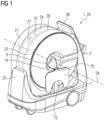
- the Fig. 1 shows a computer tomography device 1 in the form of a mobile head computer tomography device with a head shell 19 and a shoulder board 7.
- the computer tomography device 1 has the gantry 20 with a first gantry part 21, a second gantry part 22 and a third gantry part 23, the first gantry part 21 having a rotor 24 with a projection data acquisition system 27 and is mounted movably relative to the second gantry part 22 by means of a first linear guide in such a way that a translational movement of the first gantry part 21 can be carried out relative to the second gantry part 22, in particular can be carried out along the first linear guide.
- the first gantry part 21 has a rotary bearing 25 and a support structure 26, wherein the rotor 24 is connected to the support structure 26 by means of the rotary bearing 25 and is rotatably mounted relative to the support structure 26 about the system axis SA.
- the shoulder board 7 is connected to the holding device 72 by means of the pivoting device 70 and is pivotally mounted relative to the gantry 20 about a pivot axis perpendicular to the system axis SA.
- the system axis SA is horizontal and parallel to the first direction Z1 and parallel to the second direction Z2.
- the second gantry part 22 has a chassis for a horizontal transport movement of the gantry 20.
- the gantry 20 also has the touch-sensitive screen 38 for operating the computer tomography device 1.
- the gantry 20 has an opening 9, the opening 9 being designed such that an examination object can be inserted into the opening 9 along a system axis SA of the gantry 20, with the translational movement of the first gantry part 21 relative to the second gantry part 22 along the System axis SA takes place.
- the first gantry part 21 is arranged essentially in a ring shape around the system axis SA and/or that the third gantry part 23 is arranged in a substantially ring shape around the system axis SA.
- the first gantry part 21 has a back of a panel V of the gantry 20, the back of the panel V of the gantry 20 surrounding a back of the opening 9 in a ring.
- the third gantry part 23 has a front of a panel V of the gantry 20, the front of the panel V of the gantry 20 surrounding a front of the opening 9 in a ring.
- the fourth connection unit C4 is attached to the front of the panel V of the gantry 20.
- the Fig. 2 shows a computer tomography device 1 in a first operating state.
- the first gantry part 21 and the third gantry part 23 are located at the rear end of the gantry 20. This means that more space is available at the front of the gantry 20 for positioning an examination object.
- the Fig. 3 shows a sectional view of the computer tomography device 1 in the first operating state.
- the first connection is established and the second connection is released, so that the third gantry part 23 follows the translational movement of the first gantry part 21 relative to the second gantry part 22 and in particular during the translational movement of the first gantry part 21 relative to the second gantry part 22 the first gantry part 21 rests.
- the first gantry part 21 has a first connection unit C1.
- the second gantry part 22 has a second connection unit C2.
- the third gantry part 23 has a third connection unit C3, which is designed to correspond to the first connection unit C1 in such a way that the first connection can be established by means of the first connection unit C1 and the third connection unit C3, which connects the third gantry part 23 relative to the first gantry part 21 releasably fixed, the third gantry part 23 following the translational movement of the first gantry part 21 relative to the second gantry part 22 when the first connection is established.
- the third gantry part 23 has a fourth connection unit C4, which is designed to correspond to the second connection unit C2 in such a way that the second connection can be established by means of the second connection unit C2 and the fourth connection unit C4, which connects the third gantry part 23 relative to the second gantry part 22 releasably fixed, wherein during the translational movement of the first gantry part 21 relative to the second gantry part 22, the third gantry part 23 rests relative to the second gantry part 22 when the first connection is released and the second connection is established.
- the first linear guide can, for example, have a rail system 42 and a carriage system 41, which interacts with the rail system 42.
- the first gantry part 21 has the carriage system 41 and/or that the second gantry part 22 has the rail system 42.
- the gantry 20 can, for example, further have a linear drive 44 for driving the translational movement of the first gantry part 21 relative to the second gantry part 22.
- the second gantry part 22 has the holding device 72.
- the shoulder board 72 and the second connecting unit C2 can be attached to the holding device 72.
- the holding device 72 extends along the vertical direction Y.
- the smallest possible distance between the second connection unit C2 and the fourth connection unit C4 from the system axis SA is advantageous in order to reduce tilting of the third gantry part 23 when a tensile force is applied to the third via the second connection Gantry part 23 is exercised.
- the fourth connection unit C4 is located between the first gantry part 21 and the second connection unit C2 with respect to the system axis SA.
- the front of the panel V of the gantry 20 extends in a frontal plane that is essentially perpendicular to the system axis SA.
- the third gantry part 23 is mounted movably relative to the first gantry part 21 by means of a second linear guide, the second linear guide being aligned parallel to the first linear guide.
- the first connection is based on a lock which secures the third gantry part 23 in a form-fitting manner against a translational movement of the third gantry part 23 along the second linear guide relative to the first gantry part 21.
- the second linear guide has a set of mutually parallel guide shafts 53 and a set of ball bushings 51, each guide shaft of the set of mutually parallel guide shafts 53 being mounted in a corresponding ball bushing of the set of ball bushings 51 for a longitudinal movement of this guide shaft.
- the first gantry part 21 has the set of ball bushings 51 and that the third gantry part 23 has the set of mutually parallel guide shafts 53.
- first linear guide is aligned parallel to the system axis SA and/or that the second linear guide is aligned parallel to the system axis SA.
- each guide shaft of the set of mutually parallel guide shafts 53 is parallel to the system axis SA and / or that for each guide shaft of the set of mutually parallel guide shafts 53 the longitudinal movement of this guide shaft takes place along the system axis SA.
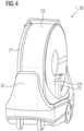
- the Fig. 4 shows the computer tomography device 1 in a second operating state.
- the first gantry part 21 and the third gantry part 23 are located at the front end of the gantry 20.
- the projection data acquisition system 27 is in a starting position of a scanning movement.
- the Fig. 5 shows a sectional view of the computer tomography device 1 in an intermediate state. It is in the intermediate state the first connection is established and the second connection is established. The computed tomography device 1 is therefore between the first operating state and the second operating state.
- the Fig. 6 shows a sectional view of the computer tomography device 1 in the second operating state.
- the first connection is released and the second connection is established, so that during the translational movement of the first gantry part 21 relative to the second gantry part 22, the third gantry part 23 rests relative to the second gantry part 22.
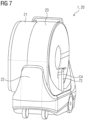
- the Fig. 7 shows the computer tomography device 1 in a third operating state.
- the first gantry part 21 is at the rear end of the gantry 20 and the third gantry part 23 is at the front end of the gantry 20.
- the Fig. 8 shows a sectional view of the computer tomography device 1 in the third operating state.
- the first connection is released and the second connection is established, so that during the translational movement of the first gantry part 21 relative to the second gantry part 22, the third gantry part 23 rests relative to the second gantry part 22.
- the second direction Z2 can be opposite to the first direction Z1.
- the first direction Z1 is parallel to the system axis SA and/or that the second direction Z2 is parallel to the system axis SA.
Landscapes
- Health & Medical Sciences (AREA)
- Life Sciences & Earth Sciences (AREA)
- Engineering & Computer Science (AREA)
- Medical Informatics (AREA)
- Radiology & Medical Imaging (AREA)
- Molecular Biology (AREA)
- Biophysics (AREA)
- Nuclear Medicine, Radiotherapy & Molecular Imaging (AREA)
- Optics & Photonics (AREA)
- Pathology (AREA)
- Physics & Mathematics (AREA)
- Biomedical Technology (AREA)
- Heart & Thoracic Surgery (AREA)
- High Energy & Nuclear Physics (AREA)
- Surgery (AREA)
- Animal Behavior & Ethology (AREA)
- General Health & Medical Sciences (AREA)
- Public Health (AREA)
- Veterinary Medicine (AREA)
- Pulmonology (AREA)
- Theoretical Computer Science (AREA)
- Apparatus For Radiation Diagnosis (AREA)
Abstract
Description
- Die Erfindung betrifft ein Computertomographiegerät. Die Erfindung betrifft ferner ein Verfahren zum Ausführen von Translationsbewegungen von Gantryteilen eines Computertomographiegeräts.
- Um ein Untersuchungsobjekt mit Hilfe eines Computertomographiegeräts zu untersuchen, kann beispielsweise eine Scanbewegung durchgeführt werden. Dabei werden das Untersuchungsobjekt und ein Projektionsdatenakquisitionssystem des Computertomographiegeräts relativ zueinander translatorisch bewegt, während mittels des Projektionsdatenakquisitionssystems Projektionsdaten von einem Untersuchungsbereich des Untersuchungsobjekts erfasst werden, insbesondere um einen mehrschichtigen medizinischen Bilddatensatz erzeugen zu können.
- In bestimmten Situation kann es vorteilhaft sein, wenn die Scanbewegung durchgeführt werden kann, während das Untersuchungsobjekt relativ zu einer Umgebung des Computertomographiegeräts, insbesondere relativ zu einem Untersuchungsraum, ruht. Dafür wird das Projektionsdatenakquisitionssystem des Computertomographiegeräts relativ zu der Umgebung des Computertomographiegeräts translatorisch bewegt, während mittels des Projektionsdatenakquisitionssystems Projektionsdaten von dem Untersuchungsbereich des Untersuchungsobjekts erfasst werden.
- Beispielsweise kann dafür ein Gantryteil des Computertomographiegeräts, der das Projektionsdatenakquisitionssystem aufweist, relativ zu einem Gantryteil des Computertomographiegeräts, der relativ zu dem Untersuchungsobjekt und relativ zu der Umgebung des Computertomographiegeräts ruht, translatorisch bewegt werden.
- Die Erfindung hat die Aufgabe, eine Alternative zu herkömmlichen Lösungen, die das Ausführen von Translationsbewegungen von Gantryteilen eines Computertomographiegeräts relativ zueinander betreffen, bereitzustellen. Jeder Gegenstand eines unabhängigen Anspruchs löst diese Aufgabe. In den abhängigen Ansprüchen sind weitere vorteilhafte Aspekte der Erfindung berücksichtigt.
- Die Erfindung betrifft ein Computertomographiegerät, aufweisend eine Gantry mit einem ersten Gantryteil, einem zweiten Gantryteil und einem dritten Gantryteil, - wobei der erste Gantryteil einen Rotor mit einem Projektionsdatenakquisitionssystem aufweist und mittels einer ersten Linearführung derart relativ zu dem zweiten Gantryteil bewegbar gelagert ist, dass eine Translationsbewegung des ersten Gantryteils relativ zu dem zweiten Gantryteil ausgeführt werden kann, insbesondere entlang der ersten Linearführung ausgeführt werden kann, wobei der erste Gantryteil eine erste Verbindungseinheit aufweist und der zweite Gantryteil eine zweite Verbindungseinheit aufweist.
- Der dritte Gantryteil weist eine dritte Verbindungseinheit auf, die derart zu der ersten Verbindungseinheit korrespondierend ausgebildet ist, dass mittels der ersten Verbindungseinheit und der dritten Verbindungseinheit eine erste Verbindung hergestellt werden kann, welche den dritten Gantryteil relativ zu dem ersten Gantryteil lösbar fixiert, wobei der dritte Gantryteil der Translationsbewegung des ersten Gantryteils relativ zu dem zweiten Gantryteil folgt, wenn die erste Verbindung hergestellt ist.
- Der dritte Gantryteil weist eine vierte Verbindungseinheit auf, die derart zu der zweiten Verbindungseinheit korrespondierend ausgebildet ist, dass mittels der zweiten Verbindungseinheit und der vierten Verbindungseinheit eine zweite Verbindung hergestellt werden kann, welche den dritten Gantryteil relativ zu dem zweiten Gantryteil lösbar fixiert, wobei während der Translationsbewegung des ersten Gantryteils relativ zu dem zweiten Gantryteil der dritte Gantryteil relativ zu dem zweiten Gantryteil ruht, wenn die erste Verbindung gelöst ist und die zweite Verbindung hergestellt ist.
- Insbesondere kann vorgesehen sein, dass während der Translationsbewegung des ersten Gantryteils relativ zu dem zweiten Gantryteil der dritte Gantryteil relativ zu dem ersten Gantryteil ruht, wenn die erste Verbindung hergestellt ist.
- Die erste Linearführung kann beispielsweise ein Schienensystem und ein Wagensystem, welches mit dem Schienensystem zusammenwirkt, aufweisen. Insbesondere kann vorgesehen sein, dass der erste Gantryteil das Wagensystem aufweist und/oder dass der zweite Gantryteil das Schienensystem aufweist. Die Gantry kann beispielsweise ferner einen Linearantrieb zum Antreiben der Translationsbewegung des ersten Gantryteils relativ zu dem zweiten Gantryteil aufweisen. Der Linearantrieb kann beispielsweise eine Gewindespindel und einen Gewindetrieb, der mit der Gewindespindel zusammenwirkt, aufweisen. Insbesondere kann vorgesehen sein, dass der erste Gantryteil den Gewindetrieb aufweist und/oder dass der zweite Gantryteil die Gewindespindel aufweist.
- Eine Ausführungsform sieht vor, dass die erste Verbindung formschlüssig ist und/oder dass die zweite Verbindung kraftschlüssig ist. Durch eine kraftschlüssige zweite Verbindung kann die Gefahr einer Klemmung im Vergleich zu einer grundsätzlich auch möglichen formschlüssigen zweiten Verbindung verringert werden. Insbesondere kann vorgesehen sein, dass sich die zweite Verbindungseinheit an einer Oberfläche des zweiten Gantryteils befindet und/oder dass sich die vierte Verbindungseinheit an einer Oberfläche des dritten Gantryteils befindet.
- Eine Ausführungsform sieht vor, dass die zweite Verbindung auf einer magnetischen Anziehung zwischen der zweiten Verbindungseinheit und der vierten Verbindungseinheit basiert. Die zweite Verbindung kann beispielsweise magnetisch sein. Durch die Verwendung einer kraftschlüssigen magnetischen zweiten Verbindung kann die Oberfläche der Gantry im Bereich der zweiten Verbindungseinheit und/oder im Bereich der vierten Verbindungseinheit reinigungsoptimiert gestaltet werden.
- Eine Ausführungsform sieht vor, dass die zweite Verbindungseinheit einen Elektromagneten aufweist und/oder dass die vierte Verbindungseinheit ein ferromagnetisches Material aufweist. Die vierte Verbindungseinheit kann beispielsweise eine ferromagnetische Platte, beispielsweise aus Stahl, aufweisen. Beispielsweise kann ein Herstellen der zweiten Verbindung durch ein Einschalten des Elektromagneten erfolgen, wenn sich das ferromagnetische Material der vierten Verbindungseinheit in einem Wirkungsbereich des Elektromagneten befindet. Beispielsweise kann ein Lösen der zweiten Verbindung durch ein Ausschalten des Elektromagneten erfolgen.
- Eine Ausführungsform sieht vor, dass die erste Verbindungseinheit einen Riegel und einen Aktor zum Verschieben des Riegels aufweist und/oder dass die dritte Verbindungseinheit zur formschlüssigen Aufnahme des Riegels eingerichtet ist. Die erste Verbindungseinheit kann beispielsweise ein Hubzylinder, insbesondere in Form eines Elektrozylinders, Pneumatikzylinders oder Hydraulikzylinders, sein.
- Es sind somit keine aktiven Komponenten auf dem dritten Gantryteil erforderlich, um die erste Verbindung und die zweite Verbindung herstellen bzw. lösen zu können. Somit ist für diese Zwecke eine Übertragung von Steuerungsdaten und/oder elektrischer Energie zum dritten Gantryteil nicht erforderlich.
- Eine Ausführungsform sieht vor, dass der dritte Gantryteil mittels einer zweiten Linearführung relativ zu dem ersten Gantryteil bewegbar gelagert ist und/oder dass die zweite Linearführung parallel zu der ersten Linearführung ausgerichtet ist.
- Eine Ausführungsform sieht vor, dass die erste Verbindung auf einer Verriegelung basiert, welche den dritten Gantryteil formschlüssig gegen eine Translationsbewegung des dritten Gantryteils entlang der zweiten Linearführung relativ zu dem ersten Gantryteil sichert.
- Eine Ausführungsform sieht vor, dass die zweite Linearführung einen Satz von zueinander parallelen Führungswellen und einen Satz von Kugelbuchsen aufweist und/oder dass jede Führungswelle des Satzes von zueinander parallelen Führungswellen in einer entsprechenden Kugelbuchse des Satzes von Kugelbuchsen für eine Längsbewegung dieser Führungswelle gelagert ist.
- Insbesondere kann vorgesehen sein, dass der erste Gantryteil den Satz von Kugelbuchsen aufweist und dass der dritte Gantryteil den Satz von zueinander parallelen Führungswellen aufweist.
- Alternativ dazu kann vorgesehen sein, dass der dritte Gantryteil den Satz von Kugelbuchsen aufweist und dass der erste Gantryteil den Satz von zueinander parallelen Führungswellen aufweist. Grundsätzlich ist es auch möglich, dass der erste Gantryteil eine erste Führungswelle des Satzes von zueinander parallelen Führungswellen und eine erste Kugelbuchse des Satzes von Kugelbuchsen aufweist und dass der dritte Gantryteil eine zu der ersten Kugelbuchse korrespondierende zweite Führungswelle des Satzes von zueinander parallelen Führungswellen und eine zu der ersten Führungswelle korrespondierende zweite Kugelbuchse des Satzes von Kugelbuchsen aufweist.
- Dadurch kann dann, wenn während der Translationsbewegung des ersten Gantryteils relativ zu dem zweiten Gantryteil der dritte Gantryteil relativ zu dem zweiten Gantryteil ruht, die Reibung zwischen dem dritten Gantryteil und dem ersten Gantryteil verringert werden. Außerdem kann auch dann, wenn während der Translationsbewegung des ersten Gantryteils relativ zu dem zweiten Gantryteil der dritte Gantryteil relativ zu dem zweiten Gantryteil ruht, das Gewicht des dritten Gantryteils von dem zweiten Gantryteil im Wesentlichen über den Satz von zueinander parallelen Führungswellen und den Satz von Kugelbuchsen aufgenommen werden, sodass es nicht erforderlich ist, die zweite Verbindung für ein Halten eines wesentlichen Teils des Gewichts des dritten Gantryteils auszulegen. Insbesondere kann der Elektromagnet der zweiten Verbindungseinheit somit weniger leistungsstark ausgeführt werden.
- Dadurch wird ein ruhiger und gleichmäßiger Lauf des dritten Gantryteils relativ zu dem ersten Gantryteil dann, wenn während der Translationsbewegung des ersten Gantryteils relativ zu dem zweiten Gantryteil der dritte Gantryteil relativ zu dem zweiten Gantryteil ruht, ermöglicht.
- Eine Ausführungsform sieht vor, dass der dritte Gantryteil wenigstens eine Führungswelle des Satzes von zueinander parallelen Führungswellen aufweist, welche eine Einkerbung zur formschlüssigen Aufnahme eines entsprechend angeordneten Riegels der ersten Verbindungseinheit aufweist. Die wenigstens eine Führungswelle des Satzes von zueinander parallelen Führungswellen kann somit die dritte Verbindungseinheit bilden. Damit ist es nicht erforderlich, zusätzlich zu den Führungswellen separate Verriegelungs-Gegenstücke einzubauen.
- Eine Ausführungsform sieht vor, dass die Gantry eine Öffnung aufweist, wobei die Öffnung derart ausgebildet ist, dass ein Untersuchungsobjekt entlang einer Systemachse der Gantry in die Öffnung eingeführt werden kann, und/oder dass die Translationsbewegung des ersten Gantryteils relativ zu dem zweiten Gantryteil entlang der Systemachse erfolgt.
- Insbesondere kann vorgesehen sein, dass die erste Linearführung parallel zu der Systemachse ausgerichtet ist und/oder dass die zweite Linearführung parallel zu der Systemachse ausgerichtet ist. Insbesondere kann vorgesehen sein, dass jede Führungswelle des Satzes von zueinander parallelen Führungswellen zu der Systemachse parallel ist und/oder dass für jede Führungswelle des Satzes von zueinander parallelen Führungswellen die Längsbewegung dieser Führungswelle entlang der Systemachse erfolgt.
- Insbesondere kann vorgesehen sein, dass der erste Gantryteil im Wesentlichen ringförmig um die Systemachse herum angeordnet ist und/oder dass der dritte Gantryteil im Wesentlichen ringförmig um die Systemachse herum angeordnet ist.
- Insbesondere kann vorgesehen sein, dass die zueinander parallelen Führungswellen des Satzes von zueinander parallelen Führungswellen um die Systemachse herum in einem im Wesentlichen gleichmäßigen auf die Systemachse bezogenen Winkelabstand voneinander angeordnet sind. Beispielsweise können drei zueinander parallele Führungswellen vorgesehen sein, die voneinander jeweils einen auf die Systemachse bezogenen Winkelabstand von 120 Grad haben.
- Insbesondere kann vorgesehen sein, dass der erste Gantryteil eine Drehlagerung und eine Tragstruktur aufweist und dass der Rotor mittels der Drehlagerung mit der Tragstruktur verbunden und relativ zu der Tragstruktur um die Systemachse drehbar gelagert ist.
- Das Untersuchungsobjekt kann beispielsweise ein Körperteil, insbesondere ein menschliches oder tierisches Körperteil, oder ein Phantom sein. Das Untersuchungsobjekt kann insbesondere ein Kopf eines Menschen sein. Das Computertomographiegerät kann insbesondere als Kopf-Computertomographiegerät und/oder als mobiles Computertomographiegerät ausgebildet sein.
- Eine Ausführungsform sieht vor, dass der erste Gantryteil eine Rückseite einer Verkleidung der Gantry aufweist, wobei die Rückseite der Verkleidung der Gantry eine Rückseite der Öffnung ringförmig umgibt, und/oder dass der dritte Gantryteil eine Vorderseite einer Verkleidung der Gantry aufweist, wobei die Vorderseite der Verkleidung der Gantry eine Vorderseite der Öffnung ringförmig umgibt.
- Eine Ausführungsform sieht vor, dass die vierte Verbindungseinheit an der Vorderseite der Verkleidung der Gantry befestigt ist. Insbesondere kann vorgesehen sein, dass sich die ferromagnetische Platte der vierten Verbindungseinheit im Wesentlichen parallel zu einer Oberfläche der Vorderseite der Verkleidung der Gantry flächig erstreckt und/oder dass eine Plattenebene der ferromagnetischen Platte zu der Systemachse im Wesentlichen senkrecht, insbesondere senkrecht, ist.
- Die Erfindung betrifft ferner ein Verfahren zum Ausführen von Translationsbewegungen von Gantryteilen eines erfindungsgemäßen Computertomographiegeräts, das Verfahren umfassend:
- ein Herstellen der ersten Verbindung,
- ein erstes Ausführen der Translationsbewegung des ersten Gantryteils relativ zu dem zweiten Gantryteil in eine erste Richtung, wobei der dritte Gantryteil der Translationsbewegung des ersten Gantryteils relativ zu dem zweiten Gantryteil folgt,
- ein erstes Ausführen der Translationsbewegung des ersten Gantryteils relativ zu dem zweiten Gantryteil in eine zweite Richtung, wobei der dritte Gantryteil der Translationsbewegung des ersten Gantryteils relativ zu dem zweiten Gantryteil folgt,
- ein Herstellen der zweiten Verbindung,
- ein Lösen der ersten Verbindung,
- ein zweites Ausführen der Translationsbewegung des ersten Gantryteils relativ zu dem zweiten Gantryteil in die erste Richtung, wobei der dritte Gantryteil relativ zu dem zweiten Gantryteil ruht.
- Insbesondere kann die zweite Richtung zu der ersten Richtung entgegengesetzt sein. Insbesondere kann vorgesehen sein, dass die erste Richtung zu der Systemachse parallel ist und/oder dass die zweite Richtung zu der Systemachse parallel ist.
- Insbesondere kann vorgesehen sein, dass nach dem ersten Ausführen der Translationsbewegung des ersten Gantryteils relativ zu dem zweiten Gantryteil in die erste Richtung und vor dem ersten Ausführen der Translationsbewegung des ersten Gantryteils relativ zu dem zweiten Gantryteil in die zweite Richtung ein Untersuchungsobjekt derart relativ zu der Gantry positioniert wird, dass durch die Translationsbewegung des ersten Gantryteils relativ zu dem zweiten Gantryteil in die zweite Richtung das Untersuchungsobjekt entlang der Systemachse der Gantry in die Öffnung eingeführt wird, wobei während der Translationsbewegung des ersten Gantryteils relativ zu dem zweiten Gantryteil in die zweite Richtung das Untersuchungsobjekt relativ zu dem zweiten Gantryteil ruht.
- Insbesondere kann vorgesehen sein, dass während des zweiten Ausführens der Translationsbewegung des ersten Gantryteils relativ zu dem zweiten Gantryteil in die erste Richtung Projektionsdaten von einem Untersuchungsbereich des Untersuchungsobjekts mittels des Projektionsdatenakquisitionssystems erfasst werden.
- Eine Ausführungsform sieht vor, dass die erste Verbindungseinheit einen Riegel und einen Aktor zum Verschieben des Riegels aufweist, wobei die dritte Verbindungseinheit zur formschlüssigen Aufnahme des Riegels eingerichtet ist, wobei die erste Verbindung hergestellt wird, indem der Riegel mittels des Aktors hin zu der dritten Verbindungseinheit verschoben und mittels der dritten Verbindungseinheit formschlüssig aufgenommen wird, wobei die erste Verbindung gelöst wird, indem der Riegel mittels des Aktors weg von der dritten Verbindungseinheit verschoben wird.
- Das Herstellen der ersten Verbindung kann beispielsweise durch eine Verriegelung erfolgen, welche den dritten Gantryteil formschlüssig gegen eine Translationsbewegung des dritten Gantryteils entlang der zweiten Linearführung relativ zu dem ersten Gantryteil sichert. Das Lösen der ersten Verbindung kann beispielsweise durch eine Entriegelung erfolgen, welche die Translationsbewegung des dritten Gantryteils entlang der zweiten Linearführung relativ zu dem ersten Gantryteil freigibt.
- Eine Ausführungsform sieht vor, dass die zweite Verbindungseinheit einen Elektromagneten aufweist, wobei die vierte Verbindungseinheit ein ferromagnetisches Material aufweist, wobei durch das erste Ausführen der Translationsbewegung des ersten Gantryteils relativ zu dem zweiten Gantryteil in die zweite Richtung das ferromagnetische Material der vierten Verbindungseinheit in einen Wirkungsbereich des Elektromagneten gebracht wird, während der Elektromagnet ausgeschaltet ist, wobei die zweite Verbindung hergestellt wird, indem der Elektromagnet eingeschaltet wird.
- Die zweite Verbindung kann beispielsweise gelöst werden, indem der Elektromagnet ausgeschaltet wird. Insbesondere kann vorgesehen sein, dass durch das erste Ausführen der Translationsbewegung des ersten Gantryteils relativ zu dem zweiten Gantryteil in die zweite Richtung die vierte Verbindungseinheit bis zu einem formschlüssigen Anschlag an die zweite Verbindungseinheit angenähert wird. Dadurch kann eine ruckartige Bewegung des ersten Gantryteils beim Einschalten des Elektromagneten sowie das damit verbundene Risiko für Beschädigungen und/oder Quetschungen vermieden werden.
- Im Rahmen der Erfindung können Merkmale, welche in Bezug auf unterschiedliche Ausführungsformen der Erfindung und/oder unterschiedliche Anspruchskategorien (Verfahren, Verwendung, Vorrichtung, System, Anordnung usw.) beschrieben sind, zu weiteren Ausführungsformen der Erfindung kombiniert werden. Beispielsweise kann ein Anspruch, der eine Vorrichtung betrifft, auch mit Merkmalen, die im Zusammenhang mit einem Verfahren beschrieben oder beansprucht sind, weitergebildet werden und umgekehrt. Funktionale Merkmale eines Verfahrens können dabei durch entsprechend ausgebildete gegenständliche Komponenten ausgeführt werden. Die Verwendung der unbestimmten Artikel "ein" bzw. "eine" schließt nicht aus, dass das betroffene Merkmal auch mehrfach vorhanden sein kann.
- Im Folgenden wird die Erfindung anhand von Ausführungsbeispielen unter Hinweis auf die beigefügten Figuren erläutert. Die Darstellung in den Figuren ist schematisch, stark vereinfacht und nicht zwingend maßstabsgetreu.
- Die
Fig. 1 zeigt ein Computertomographiegerät in Form eines mobilen Kopf-Computertomographiegeräts mit einer Kopfschale und einer Körperstützvorrichtung. - Die
Fig. 2 zeigt ein Computertomographiegerät in einem ersten Betriebszustand. - Die
Fig. 3 zeigt eine Schnittansicht des Computertomographiegeräts in dem ersten Betriebszustand. - Die
Fig. 4 zeigt das Computertomographiegerät in einem zweiten Betriebszustand. - Die
Fig. 5 zeigt eine Schnittansicht des Computertomographiegeräts in einem Zwischenzustand. - Die
Fig. 6 zeigt eine Schnittansicht des Computertomographiegeräts in dem zweiten Betriebszustand. - Die
Fig. 7 zeigt das Computertomographiegerät in einem dritten Betriebszustand. - Die
Fig. 8 zeigt eine Schnittansicht des Computertomographiegeräts in dem dritten Betriebszustand. - Die
Fig. 9 zeigt ein Ablaufdiagramm eines Verfahrens zum Ausführen von Translationsbewegungen von Gantryteilen eines Computertomographiegeräts - Die
Fig. 1 zeigt ein Computertomographiegerät 1 in Form eines mobilen Kopf-Computertomographiegeräts mit einer Kopfschale 19 und einem Schulterbrett 7. Das Computertomographiegerät 1 weist die Gantry 20 mit einem ersten Gantryteil 21, einem zweiten Gantryteil 22 und einem dritten Gantryteil 23, wobei der erste Gantryteil 21 einen Rotor 24 mit einem Projektionsdatenakquisitionssystem 27 aufweist und mittels einer ersten Linearführung derart relativ zu dem zweiten Gantryteil 22 bewegbar gelagert ist, dass eine Translationsbewegung des ersten Gantryteils 21 relativ zu dem zweiten Gantryteil 22 ausgeführt werden kann, insbesondere entlang der ersten Linearführung ausgeführt werden kann. - Der erste Gantryteil 21 weist eine Drehlagerung 25 und eine Tragstruktur 26 auf, wobei der Rotor 24 mittels der Drehlagerung 25 mit der Tragstruktur 26 verbunden und relativ zu der Tragstruktur 26 um die Systemachse SA drehbar gelagert ist. Das Schulterbrett 7 ist mittels der Schwenkvorrichtung 70 mit der Haltevorrichtung 72 verbunden und relativ zu der Gantry 20 um eine zu der Systemachse SA senkrechte Schwenkachse schwenkbar gelagert. Die Systemachse SA ist horizontal und parallel zu der ersten Richtung Z1 und parallel zu der zweiten Richtung Z2. Der zweite Gantryteil 22 weist ein Fahrwerk für eine horizontale Transportbewegung der Gantry 20 auf. Die Gantry 20 weist ferner den berührungsempfindlichen Bildschirm 38 zur Bedienung des Computertomographiegeräts 1 auf.
- Die Gantry 20 weist eine Öffnung 9 auf, wobei die Öffnung 9 derart ausgebildet ist, dass ein Untersuchungsobjekt entlang einer Systemachse SA der Gantry 20 in die Öffnung 9 eingeführt werden kann, wobei die Translationsbewegung des ersten Gantryteils 21 relativ zu dem zweiten Gantryteil 22 entlang der Systemachse SA erfolgt. Insbesondere ist vorgesehen, dass der erste Gantryteil 21 im Wesentlichen ringförmig um die Systemachse SA herum angeordnet ist und/oder dass der dritte Gantryteil 23 im Wesentlichen ringförmig um die Systemachse SA herum angeordnet ist.
- Der erste Gantryteil 21 weist eine Rückseite einer Verkleidung V der Gantry 20 auf, wobei die Rückseite der Verkleidung V der Gantry 20 eine Rückseite der Öffnung 9 ringförmig umgibt. Der dritte Gantryteil 23 weist eine Vorderseite einer Verkleidung V der Gantry 20 auf, wobei die Vorderseite der Verkleidung V der Gantry 20 eine Vorderseite der Öffnung 9 ringförmig umgibt. Die vierte Verbindungseinheit C4 ist an der Vorderseite der Verkleidung V der Gantry 20 befestigt.
- Die
Fig. 2 zeigt ein Computertomographiegerät 1 in einem ersten Betriebszustand. In dem ersten Betriebszustand befinden sich der erste Gantryteil 21 und der dritte Gantryteil 23 am hinteren Ende der Gantry 20. Dadurch steht mehr Platz an der Vorderseite der Gantry 20 für eine Positionierung eines Untersuchungsobjekts zu Verfügung. - Die
Fig. 3 zeigt eine Schnittansicht des Computertomographiegeräts 1 in dem ersten Betriebszustand. In dem ersten Betriebszustand ist die erste Verbindung hergestellt und die zweite Verbindung gelöst, sodass der dritte Gantryteil 23 der Translationsbewegung des ersten Gantryteils 21 relativ zu dem zweiten Gantryteil 22 folgt und insbesondere während der Translationsbewegung des ersten Gantryteils 21 relativ zu dem zweiten Gantryteil 22 relativ zu dem ersten Gantryteil 21 ruht. Der erste Gantryteil 21 weist eine erste Verbindungseinheit C1 auf. Der zweite Gantryteil 22 weist eine zweite Verbindungseinheit C2 auf. - Der dritte Gantryteil 23 weist eine dritte Verbindungseinheit C3 auf, die derart zu der ersten Verbindungseinheit C1 korrespondierend ausgebildet ist, dass mittels der ersten Verbindungseinheit C1 und der dritten Verbindungseinheit C3 die erste Verbindung hergestellt werden kann, welche den dritten Gantryteil 23 relativ zu dem ersten Gantryteil 21 lösbar fixiert, wobei der dritte Gantryteil 23 der Translationsbewegung des ersten Gantryteils 21 relativ zu dem zweiten Gantryteil 22 folgt, wenn die erste Verbindung hergestellt ist.
- Der dritte Gantryteil 23 weist eine vierte Verbindungseinheit C4 auf, die derart zu der zweiten Verbindungseinheit C2 korrespondierend ausgebildet ist, dass mittels der zweiten Verbindungseinheit C2 und der vierten Verbindungseinheit C4 die zweite Verbindung hergestellt werden kann, welche den dritten Gantryteil 23 relativ zu dem zweiten Gantryteil 22 lösbar fixiert, wobei während der Translationsbewegung des ersten Gantryteils 21 relativ zu dem zweiten Gantryteil 22 der dritte Gantryteil 23 relativ zu dem zweiten Gantryteil 22 ruht, wenn die erste Verbindung gelöst ist und die zweite Verbindung hergestellt ist.
- Die erste Linearführung kann beispielsweise ein Schienensystem 42 und ein Wagensystem 41, welches mit dem Schienensystem 42 zusammenwirkt, aufweisen. Insbesondere kann vorgesehen sein, dass der erste Gantryteil 21 das Wagensystem 41 aufweist und/oder dass der zweite Gantryteil 22 das Schienensystem 42 aufweist. Die Gantry 20 kann beispielsweise ferner einen Linearantrieb 44 zum Antreiben der Translationsbewegung des ersten Gantryteils 21 relativ zu dem zweiten Gantryteil 22 aufweisen.
- Der zweite Gantryteil 22 weist die Haltevorrichtung 72 auf. An der Haltevorrichtung 72 können das Schulterbrett 72 und die zweite Verbindungseinheit C2 befestigt werden. Die Haltevorrichtung 72 erstreckt sich entlang der vertikalen Richtung Y. Ein möglichst kleiner Abstand der zweiten Verbindungseinheit C2 und der vierten Verbindungseinheit C4 zur Systemachse SA ist vorteilhaft, um ein Verkanten des dritten Gantryteils 23 zu verringern, wenn über die zweite Verbindung eine Zugkraft auf das dritte Gantryteil 23 ausgeübt wird. Die vierte Verbindungseinheit C4 befindet sich in Bezug auf die Systemachse SA zwischen dem ersten Gantryteil 21 und der zweiten Verbindungseinheit C2. Die Vorderseite der Verkleidung V der Gantry 20 erstreckt sich in einer Frontalebene, die zu der Systemachse SA im Wesentlichen senkrecht ist.
- Der dritte Gantryteil 23 ist mittels einer zweiten Linearführung relativ zu dem ersten Gantryteil 21 bewegbar gelagert, wobei die zweite Linearführung parallel zu der ersten Linearführung ausgerichtet ist. Die erste Verbindung basiert auf einer Verriegelung, welche den dritten Gantryteil 23 formschlüssig gegen eine Translationsbewegung des dritten Gantryteils 23 entlang der zweiten Linearführung relativ zu dem ersten Gantryteil 21 sichert.
- Die zweite Linearführung weist einen Satz von zueinander parallelen Führungswellen 53 und einen Satz von Kugelbuchsen 51 auf, wobei jede Führungswelle des Satzes von zueinander parallelen Führungswellen 53 in einer entsprechenden Kugelbuchse des Satzes von Kugelbuchsen 51 für eine Längsbewegung dieser Führungswelle gelagert ist. Insbesondere ist vorgesehen, dass der erste Gantryteil 21 den Satz von Kugelbuchsen 51 aufweist und dass der dritte Gantryteil 23 den Satz von zueinander parallelen Führungswellen 53 aufweist.
- Insbesondere ist vorgesehen, dass die erste Linearführung parallel zu der Systemachse SA ausgerichtet ist und/oder dass die zweite Linearführung parallel zu der Systemachse SA ausgerichtet ist. Insbesondere kann vorgesehen sein, dass jede Führungswelle des Satzes von zueinander parallelen Führungswellen 53 zu der Systemachse SA parallel ist und/oder dass für jede Führungswelle des Satzes von zueinander parallelen Führungswellen 53 die Längsbewegung dieser Führungswelle entlang der Systemachse SA erfolgt.
- Die
Fig. 4 zeigt das Computertomographiegerät 1 in einem zweiten Betriebszustand. In dem zweiten Betriebszustand befinden sich der erste Gantryteil 21 und der dritte Gantryteil 23 am vorderen Ende der Gantry 20. Dadurch befindet sich das Projektionsdatenakquisitionssystem 27 in einer Start-Position einer Scanbewegung. - Die
Fig. 5 zeigt eine Schnittansicht des Computertomographiegeräts 1 in einem Zwischenzustand. In dem Zwischenzustand ist die erste Verbindung hergestellt und die zweite Verbindung hergestellt. Das Computertomographiegerät 1 befindet sich somit zwischen dem ersten Betriebszustand und dem zweiten Betriebszustand. - Die
Fig. 6 zeigt eine Schnittansicht des Computertomographiegeräts 1 in dem zweiten Betriebszustand. In dem zweiten Betriebszustand ist die erste Verbindung gelöst und die zweite Verbindung hergestellt, sodass während der Translationsbewegung des ersten Gantryteils 21 relativ zu dem zweiten Gantryteil 22 der dritte Gantryteil 23 relativ zu dem zweiten Gantryteil 22 ruht. - Die
Fig. 7 zeigt das Computertomographiegerät 1 in einem dritten Betriebszustand. In dem dritten Betriebszustand befindet sich der erste Gantryteil 21 am hinteren Ende der Gantry 20 und der dritte Gantryteil 23 am vorderen Ende der Gantry 20. - Die
Fig. 8 zeigt eine Schnittansicht des Computertomographiegeräts 1 in dem dritten Betriebszustand. In dem dritten Betriebszustand ist die erste Verbindung gelöst und die zweite Verbindung hergestellt, sodass während der Translationsbewegung des ersten Gantryteils 21 relativ zu dem zweiten Gantryteil 22 der dritte Gantryteil 23 relativ zu dem zweiten Gantryteil 22 ruht. - Die
Fig. 9 zeigt ein Ablaufdiagramm eines Verfahrens zum Ausführen von Translationsbewegungen von Gantryteilen eines Computertomographiegeräts 1, das Verfahren umfassend: - ein Herstellen M1 der ersten Verbindung,
- ein erstes Ausführen M2 der Translationsbewegung des ersten Gantryteils 21 relativ zu dem zweiten Gantryteil 22 in eine erste Richtung Z1, wobei der dritte Gantryteil 23 der Translationsbewegung des ersten Gantryteils 21 relativ zu dem zweiten Gantryteil 22 folgt,
- ein erstes Ausführen M3 der Translationsbewegung des ersten Gantryteils 21 relativ zu dem zweiten Gantryteil 22 in eine zweite Richtung Z2, wobei der dritte Gantryteil 23 der Translationsbewegung des ersten Gantryteils 21 relativ zu dem zweiten Gantryteil 22 folgt,
- ein Herstellen M4 der zweiten Verbindung,
- ein Lösen M5 der ersten Verbindung,
- ein zweites Ausführen M6 der Translationsbewegung des ersten Gantryteils 21 relativ zu dem zweiten Gantryteil 22 in die erste Richtung Z1, wobei der dritte Gantryteil 23 relativ zu dem zweiten Gantryteil 22 ruht.
- Insbesondere kann die zweite Richtung Z2 zu der ersten Richtung Z1 entgegengesetzt sein. Insbesondere kann vorgesehen sein, dass die erste Richtung Z1 zu der Systemachse SA parallel ist und/oder dass die zweite Richtung Z2 zu der Systemachse SA parallel ist.
Claims (15)
- Computertomographiegerät (1), aufweisend eine Gantry (20) mit einem ersten Gantryteil (21), einem zweiten Gantryteil (22) und einem dritten Gantryteil (23),- wobei der erste Gantryteil (21) einen Rotor (24) mit einem Projektionsdatenakquisitionssystem (27) aufweist und mittels einer ersten Linearführung derart relativ zu dem zweiten Gantryteil (22) bewegbar gelagert ist, dass eine Translationsbewegung des ersten Gantryteils (21) relativ zu dem zweiten Gantryteil (22) ausgeführt werden kann,- wobei der erste Gantryteil (21) eine erste Verbindungseinheit (C1) aufweist und der zweite Gantryteil (22) eine zweite Verbindungseinheit (C2) aufweist,- wobei der dritte Gantryteil (23) eine dritte Verbindungseinheit (C3) aufweist, die derart zu der ersten Verbindungseinheit (C1) korrespondierend ausgebildet ist, dass mittels der ersten Verbindungseinheit (C1) und der dritten Verbindungseinheit (C3) eine erste Verbindung hergestellt werden kann, welche den dritten Gantryteil (23) relativ zu dem ersten Gantryteil (21) lösbar fixiert, wobei der dritte Gantryteil (23) der Translationsbewegung des ersten Gantryteils (21) relativ zu dem zweiten Gantryteil (22) folgt, wenn die erste Verbindung hergestellt ist,- wobei der dritte Gantryteil (23) eine vierte Verbindungseinheit (C4) aufweist, die derart zu der zweiten Verbindungseinheit (C2) korrespondierend ausgebildet ist, dass mittels der zweiten Verbindungseinheit (C2) und der vierten Verbindungseinheit (C4) eine zweite Verbindung hergestellt werden kann, welche den dritten Gantryteil (23) relativ zu dem zweiten Gantryteil (22) lösbar fixiert, wobei während der Translationsbewegung des ersten Gantryteils (21) relativ zu dem zweiten Gantryteil (22) der dritte Gantryteil (23) relativ zu dem zweiten Gantryteil (22) ruht, wenn die erste Verbindung gelöst ist und die zweite Verbindung hergestellt ist.
- Computertomographiegerät (1) nach Anspruch 1,- wobei die erste Verbindung formschlüssig ist und/oder- wobei die zweite Verbindung kraftschlüssig ist.
- Computertomographiegerät (1) nach Anspruch 1 oder 2,- wobei die zweite Verbindung auf einer magnetischen Anziehung zwischen der zweiten Verbindungseinheit (C2) und der vierten Verbindungseinheit (C4) basiert.
- Computertomographiegerät (1) nach einem der Ansprüche 1 bis 3,- wobei die zweite Verbindungseinheit (C2) einen Elektromagneten aufweist,- wobei die vierte Verbindungseinheit (C4) ein ferromagnetisches Material aufweist.
- Computertomographiegerät (1) nach einem der Ansprüche 1 bis 4,- wobei die erste Verbindungseinheit (C1) einen Riegel und einen Aktor zum Verschieben des Riegels aufweist,- wobei die dritte Verbindungseinheit (C3) zur formschlüssigen Aufnahme des Riegels eingerichtet ist.
- Computertomographiegerät (1) nach einem der Ansprüche 1 bis 5,- wobei der dritte Gantryteil (23) mittels einer zweiten Linearführung relativ zu dem ersten Gantryteil (21) bewegbar gelagert ist,- wobei die zweite Linearführung parallel zu der ersten Linearführung ausgerichtet ist.
- Computertomographiegerät (1) nach Anspruch 6,- wobei die erste Verbindung auf einer Verriegelung basiert, welche den dritten Gantryteil (23) formschlüssig gegen eine Translationsbewegung des dritten Gantryteils (23) entlang der zweiten Linearführung relativ zu dem ersten Gantryteil (21) sichert.
- Computertomographiegerät (1) nach Anspruch 6 oder 7,- wobei die zweite Linearführung einen Satz von zueinander parallelen Führungswellen (53) und einen Satz von Kugelbuchsen (51) aufweist,- wobei jede Führungswelle des Satzes von zueinander parallelen Führungswellen (53) in einer entsprechenden Kugelbuchse des Satzes von Kugelbuchsen (51) für eine Längsbewegung dieser Führungswelle gelagert ist.
- Computertomographiegerät (1) nach Anspruch 8,- wobei der dritte Gantryteil (23) wenigstens eine Führungswelle des Satzes von zueinander parallelen Führungswellen (53) aufweist, welche eine Einkerbung zur formschlüssigen Aufnahme eines entsprechend angeordneten Riegels der ersten Verbindungseinheit (C1) aufweist.
- Computertomographiegerät (1) nach einem der Ansprüche 1 bis 9,- wobei die Gantry (20) eine Öffnung (9) aufweist, wobei die Öffnung (9) derart ausgebildet ist, dass ein Untersuchungsobjekt entlang einer Systemachse (SA) der Gantry (20) in die Öffnung (9) eingeführt werden kann,- wobei die Translationsbewegung des ersten Gantryteils (21) relativ zu dem zweiten Gantryteil (22) entlang der Systemachse (SA) erfolgt.
- Computertomographiegerät (1) nach Anspruch 10,- wobei der erste Gantryteil (21) eine Rückseite einer Verkleidung (V) der Gantry (20) aufweist, wobei die Rückseite der Verkleidung (V) der Gantry (20) eine Rückseite der Öffnung (9) ringförmig umgibt,- wobei der dritte Gantryteil (23) eine Vorderseite einer Verkleidung (V) der Gantry (20) aufweist, wobei die Vorderseite der Verkleidung (V) der Gantry (20) eine Vorderseite der Öffnung (9) ringförmig umgibt.
- Computertomographiegerät (1) nach Anspruch 11,- wobei die vierte Verbindungseinheit (C4) an der Vorderseite der Verkleidung (V) der Gantry (20) befestigt ist.
- Verfahren zum Ausführen von Translationsbewegungen von Gantryteilen eines Computertomographiegeräts (1) nach einem der Ansprüche 1 bis 12, das Verfahren umfassend:- ein Herstellen (M1) der ersten Verbindung,- ein erstes Ausführen (M2) der Translationsbewegung des ersten Gantryteils (21) relativ zu dem zweiten Gantryteil (22) in eine erste Richtung (Z1), wobei der dritte Gantryteil (23) der Translationsbewegung des ersten Gantryteils (21) relativ zu dem zweiten Gantryteil (22) folgt,- ein erstes Ausführen (M3) der Translationsbewegung des ersten Gantryteils (21) relativ zu dem zweiten Gantryteil (22) in eine zweite Richtung (Z2), wobei der dritte Gantryteil (23) der Translationsbewegung des ersten Gantryteils (21) relativ zu dem zweiten Gantryteil (22) folgt,- ein Herstellen (M4) der zweiten Verbindung,- ein Lösen (M5) der ersten Verbindung,- ein zweites Ausführen (M6) der Translationsbewegung des ersten Gantryteils (21) relativ zu dem zweiten Gantryteil (22) in die erste Richtung (Z1), wobei der dritte Gantryteil (23) relativ zu dem zweiten Gantryteil (22) ruht.
- Verfahren nach Anspruch 13,- wobei die erste Verbindungseinheit (C1) einen Riegel und einen Aktor zum Verschieben des Riegels aufweist,- wobei die dritte Verbindungseinheit (C3) zur formschlüssigen Aufnahme des Riegels eingerichtet ist,- wobei die erste Verbindung hergestellt wird, indem der Riegel mittels des Aktors hin zu der dritten Verbindungseinheit (C3) verschoben und mittels der dritten Verbindungseinheit (C3) formschlüssig aufgenommen wird,- wobei die erste Verbindung gelöst wird, indem der Riegel mittels des Aktors weg von der dritten Verbindungseinheit (C3) verschoben wird.
- Verfahren nach Anspruch 13 oder 14,- wobei die zweite Verbindungseinheit (C2) einen Elektromagneten aufweist,- wobei die vierte Verbindungseinheit (C4) ein ferromagnetisches Material aufweist,- wobei durch das erste Ausführen (M3) der Translationsbewegung des ersten Gantryteils (21) relativ zu dem zweiten Gantryteil (22) in die zweite Richtung (Z2) das ferromagnetische Material der vierten Verbindungseinheit (C4) in einen Wirkungsbereich des Elektromagneten gebracht wird, während der Elektromagnet ausgeschaltet ist,- wobei die zweite Verbindung hergestellt wird, indem der Elektromagnet eingeschaltet wird.
Priority Applications (3)
| Application Number | Priority Date | Filing Date | Title |
|---|---|---|---|
| EP22199104.5A EP4265189B1 (de) | 2022-09-30 | 2022-09-30 | Computertomographiegerät und verfahren zum ausführen von translationsbewegungen von gantryteilen eines computertomographiegeräts |
| CN202311268059.4A CN117814820A (zh) | 2022-09-30 | 2023-09-28 | 计算机断层摄影设备和用于执行计算机断层摄影设备的机架部分的平动的方法 |
| US18/478,742 US12440177B2 (en) | 2022-09-30 | 2023-09-29 | Computed tomography device and method for executing translation movements of gantry parts of a computed tomography device |
Applications Claiming Priority (1)
| Application Number | Priority Date | Filing Date | Title |
|---|---|---|---|
| EP22199104.5A EP4265189B1 (de) | 2022-09-30 | 2022-09-30 | Computertomographiegerät und verfahren zum ausführen von translationsbewegungen von gantryteilen eines computertomographiegeräts |
Publications (3)
| Publication Number | Publication Date |
|---|---|
| EP4265189A1 true EP4265189A1 (de) | 2023-10-25 |
| EP4265189C0 EP4265189C0 (de) | 2025-09-10 |
| EP4265189B1 EP4265189B1 (de) | 2025-09-10 |
Family
ID=83546955
Family Applications (1)
| Application Number | Title | Priority Date | Filing Date |
|---|---|---|---|
| EP22199104.5A Active EP4265189B1 (de) | 2022-09-30 | 2022-09-30 | Computertomographiegerät und verfahren zum ausführen von translationsbewegungen von gantryteilen eines computertomographiegeräts |
Country Status (3)
| Country | Link |
|---|---|
| US (1) | US12440177B2 (de) |
| EP (1) | EP4265189B1 (de) |
| CN (1) | CN117814820A (de) |
Citations (3)
| Publication number | Priority date | Publication date | Assignee | Title |
|---|---|---|---|---|
| EP3342348A1 (de) * | 2016-12-29 | 2018-07-04 | Samsung Electronics Co., Ltd. | Medizinische vorrichtung |
| CN114098790A (zh) * | 2021-12-24 | 2022-03-01 | 南京安科医疗科技有限公司 | 一种ct扫描移动装置及其扫描方法 |
| CN114947922A (zh) * | 2022-06-09 | 2022-08-30 | 上海西门子医疗器械有限公司 | 构建ct装置在双源宽体模式下的图像数据的方法及介质 |
Family Cites Families (23)
| Publication number | Priority date | Publication date | Assignee | Title |
|---|---|---|---|---|
| DE19505276A1 (de) * | 1995-02-16 | 1996-08-29 | Siemens Ag | Computertomograph |
| US5799054A (en) * | 1996-12-31 | 1998-08-25 | General Electric Company | Methods and apparatus for stabilizing a gantry in a computed tomography system |
| DE19908494A1 (de) * | 1999-02-26 | 2000-10-05 | Siemens Ag | Computertomograph |
| CN100482165C (zh) * | 2002-06-11 | 2009-04-29 | 分离成像有限责任公司 | 用于x射线成像的悬臂式支架装置 |
| US6865254B2 (en) * | 2002-07-02 | 2005-03-08 | Pencilbeam Technologies Ab | Radiation system with inner and outer gantry parts |
| DE60333018D1 (de) * | 2002-08-21 | 2010-07-29 | Breakaway Imaging Llc | Gerüstpositionierungsgerät für röntgengeräte |
| DE10304661B4 (de) * | 2003-02-05 | 2007-03-01 | Siemens Ag | Kühlsystem und Verfahren zur Kühlung einer Gantry |
| US7564945B2 (en) * | 2005-02-11 | 2009-07-21 | University Of Florida Research Foundation, Inc. | System including computed tomography device for image guided treatment |
| WO2014189048A1 (ja) * | 2013-05-22 | 2014-11-27 | 株式会社 東芝 | X線コンピュータ断層撮影装置、天板制御装置、および天板制御方法 |
| US8971480B2 (en) * | 2013-06-07 | 2015-03-03 | General Electric Company | System and method for mounting x-ray tube on a CT gantry for high G-load applications |
| US9895113B2 (en) * | 2013-09-27 | 2018-02-20 | General Electric Company | Systems and methods for planar imaging with detectors having moving detector heads |
| US9192346B2 (en) * | 2013-12-19 | 2015-11-24 | General Electric Company | Systems and methods for multi-modality imaging |
| US10016171B2 (en) * | 2014-11-12 | 2018-07-10 | Epica International, Inc. | Radiological imaging device with improved functionality |
| JP6611428B2 (ja) * | 2014-12-09 | 2019-11-27 | キヤノン株式会社 | マンモ断層撮像システム |
| US10182777B2 (en) * | 2016-02-22 | 2019-01-22 | Morpho Detection, Llc | Open drum gantry for computed tomography system |
| DE102016204006B4 (de) * | 2016-03-11 | 2025-06-18 | Siemens Healthineers Ag | Anordnung mit einem stationären Teil und einem ersten rotierenden Teil einer Gantry eines Computertomographiegeräts und Verfahren zur Wartung einer Komponente einer Gantry eines Computertomographiegeräts |
| DE102016208123B4 (de) * | 2016-05-11 | 2020-03-19 | Siemens Healthcare Gmbh | Verfahren und System zum Ausführen einer Scanbewegung einer Bildgebungsdaten-Akquisitionseinheit |
| US10267930B2 (en) * | 2016-09-30 | 2019-04-23 | Shanghai United Imaging Healthcare Co., Ltd. | Systems for PET imaging |
| US10624596B2 (en) * | 2016-11-23 | 2020-04-21 | Mobius Imaging, Llc | Cantilevered x-ray CT system for multi-axis imaging |
| DE102018211669B4 (de) * | 2018-07-12 | 2020-01-23 | Siemens Healthcare Gmbh | Omnidirektionales Fahrwerk für eine Gantry eines Computertomographiegeräts |
| DE102019207419B3 (de) * | 2019-05-21 | 2020-10-29 | Siemens Healthcare Gmbh | Verfahren zur Generierung von Bilddaten, Computertomographie-System und Computerprogrammprodukt |
| DE102019209543A1 (de) * | 2019-06-28 | 2020-09-17 | Siemens Healthcare Gmbh | Verfahren zum Bereitstellen einer Kollisionsinformation und medizinische Bildgebungsvorrichtung |
| WO2022060793A1 (en) * | 2020-09-15 | 2022-03-24 | Mobius Imaging, Llc | Medical imaging device and methods |
-
2022
- 2022-09-30 EP EP22199104.5A patent/EP4265189B1/de active Active
-
2023
- 2023-09-28 CN CN202311268059.4A patent/CN117814820A/zh active Pending
- 2023-09-29 US US18/478,742 patent/US12440177B2/en active Active
Patent Citations (3)
| Publication number | Priority date | Publication date | Assignee | Title |
|---|---|---|---|---|
| EP3342348A1 (de) * | 2016-12-29 | 2018-07-04 | Samsung Electronics Co., Ltd. | Medizinische vorrichtung |
| CN114098790A (zh) * | 2021-12-24 | 2022-03-01 | 南京安科医疗科技有限公司 | 一种ct扫描移动装置及其扫描方法 |
| CN114947922A (zh) * | 2022-06-09 | 2022-08-30 | 上海西门子医疗器械有限公司 | 构建ct装置在双源宽体模式下的图像数据的方法及介质 |
Also Published As
| Publication number | Publication date |
|---|---|
| EP4265189C0 (de) | 2025-09-10 |
| US12440177B2 (en) | 2025-10-14 |
| CN117814820A (zh) | 2024-04-05 |
| US20240108295A1 (en) | 2024-04-04 |
| EP4265189B1 (de) | 2025-09-10 |
Similar Documents
| Publication | Publication Date | Title |
|---|---|---|
| DE102015218025B4 (de) | Aufzugsystem | |
| DE102015013488B4 (de) | Mobilkran mit Ballastaufnahmevorrichtung | |
| DE102007003878B4 (de) | Partikeltherapie-Anlage mit beweglichem Bodensegment | |
| DE102017106468A1 (de) | Rotatives Beaufschlagen einer Herstellungsplatte zum additiven Herstellen | |
| DE102012210546A1 (de) | Vorrichtung zum einspannen eines blechs für ein fahrzeug | |
| DE102007011399A1 (de) | Partikeltherapie-Anlage | |
| EP0277545A2 (de) | Vorrichtung zum Aufbringen einer Hülse auf einen Druckwerkzylinder | |
| EP1248272A1 (de) | Verfahren zum Prüfen von Objekten, insbesondere zur Feststellung von Fehlern oder Unregelmässigkeiten in denselben mittels Röntgenstrahlung, sowie Vorrichtung zur Durchführung des Verfahrens | |
| EP3766640B1 (de) | Magnetfuss | |
| DE102015105604B3 (de) | Vorrichtung und Verfahren zur Beflockung | |
| DE3325693C2 (de) | Vorrichtung zum Be- und Entladen einer Vulkanisierpresse für Kraftfahrzeugreifen | |
| EP4171960B1 (de) | Druckvorrichtung und drucksystem mit schablonenmagazin zum bedrucken flächiger substrate | |
| DE102018101734A1 (de) | Angetriebene trittbrettbaugruppe und verfahren zu deren betrieb | |
| EP4265189B1 (de) | Computertomographiegerät und verfahren zum ausführen von translationsbewegungen von gantryteilen eines computertomographiegeräts | |
| EP3200959B1 (de) | Manipulator zur erzeugung einer translationsbewegung | |
| WO2002022478A2 (de) | Be- und entladevorrichtung für rollenmaterial sowie kombination einer druckvorrichtung mit einer be- und entladevorrichtung | |
| EP2539115A1 (de) | Manipulationsvorrichtung | |
| DE10311309B4 (de) | Tomographie-Abbildungssystem mit einer Aufnahmeeinheit und einem Patientenliegetisch mit horizontal verfahrbarem Patientenbrett | |
| DE102024206036A1 (de) | Gantry für ein Computertomographiegerät und Verfahren zum Ausführen einer Translationsbewegung in einer Gantry | |
| DE10111798A1 (de) | Mobiles medizintechnisches Gerät und Verwendung eines elektrischen Direktantriebs für ein derartiges medizintechnisches Gerät | |
| DE102019203460A1 (de) | Patiententisch mit einer Auflagefläche für einen Patienten | |
| EP4360560A1 (de) | System mit computertomographie-gantry und hubvorrichtung | |
| DE102021104519B4 (de) | Vorrichtung zum Öffnen und Verschließen einer Zugriffsöffnung in einer Fahrzeugkarosserie | |
| DE102018209222A1 (de) | Vorrichtung, umfassend ein metallurgisches Gefäß | |
| DE102022202048B4 (de) | System und Verfahren zum Bewegen einer Computertomographie-Gantry |
Legal Events
| Date | Code | Title | Description |
|---|---|---|---|
| PUAI | Public reference made under article 153(3) epc to a published international application that has entered the european phase |
Free format text: ORIGINAL CODE: 0009012 |
|
| STAA | Information on the status of an ep patent application or granted ep patent |
Free format text: STATUS: THE APPLICATION HAS BEEN PUBLISHED |
|
| AK | Designated contracting states |
Kind code of ref document: A1 Designated state(s): AL AT BE BG CH CY CZ DE DK EE ES FI FR GB GR HR HU IE IS IT LI LT LU LV MC MK MT NL NO PL PT RO RS SE SI SK SM TR |
|
| STAA | Information on the status of an ep patent application or granted ep patent |
Free format text: STATUS: REQUEST FOR EXAMINATION WAS MADE |
|
| 17P | Request for examination filed |
Effective date: 20231103 |
|
| RBV | Designated contracting states (corrected) |
Designated state(s): AL AT BE BG CH CY CZ DE DK EE ES FI FR GB GR HR HU IE IS IT LI LT LU LV MC MK MT NL NO PL PT RO RS SE SI SK SM TR |
|
| RAP1 | Party data changed (applicant data changed or rights of an application transferred) |
Owner name: SIEMENS HEALTHINEERS AG |
|
| GRAP | Despatch of communication of intention to grant a patent |
Free format text: ORIGINAL CODE: EPIDOSNIGR1 |
|
| STAA | Information on the status of an ep patent application or granted ep patent |
Free format text: STATUS: GRANT OF PATENT IS INTENDED |
|
| INTG | Intention to grant announced |
Effective date: 20250519 |
|
| GRAS | Grant fee paid |
Free format text: ORIGINAL CODE: EPIDOSNIGR3 |
|
| GRAA | (expected) grant |
Free format text: ORIGINAL CODE: 0009210 |
|
| STAA | Information on the status of an ep patent application or granted ep patent |
Free format text: STATUS: THE PATENT HAS BEEN GRANTED |
|
| AK | Designated contracting states |
Kind code of ref document: B1 Designated state(s): AL AT BE BG CH CY CZ DE DK EE ES FI FR GB GR HR HU IE IS IT LI LT LU LV MC MK MT NL NO PL PT RO RS SE SI SK SM TR |
|
| REG | Reference to a national code |
Ref country code: GB Ref legal event code: FG4D Free format text: NOT ENGLISH |
|
| REG | Reference to a national code |
Ref country code: CH Ref legal event code: EP |
|
| REG | Reference to a national code |
Ref country code: IE Ref legal event code: FG4D Free format text: LANGUAGE OF EP DOCUMENT: GERMAN |
|
| U01 | Request for unitary effect filed |
Effective date: 20250910 |
|
| U07 | Unitary effect registered |
Designated state(s): AT BE BG DE DK EE FI FR IT LT LU LV MT NL PT RO SE SI Effective date: 20250915 |
|
| U20 | Renewal fee for the european patent with unitary effect paid |
Year of fee payment: 4 Effective date: 20250919 |
|
| PG25 | Lapsed in a contracting state [announced via postgrant information from national office to epo] |
Ref country code: NO Free format text: LAPSE BECAUSE OF FAILURE TO SUBMIT A TRANSLATION OF THE DESCRIPTION OR TO PAY THE FEE WITHIN THE PRESCRIBED TIME-LIMIT Effective date: 20251210 |
|
| PG25 | Lapsed in a contracting state [announced via postgrant information from national office to epo] |
Ref country code: HR Free format text: LAPSE BECAUSE OF FAILURE TO SUBMIT A TRANSLATION OF THE DESCRIPTION OR TO PAY THE FEE WITHIN THE PRESCRIBED TIME-LIMIT Effective date: 20250910 |
|
| PG25 | Lapsed in a contracting state [announced via postgrant information from national office to epo] |
Ref country code: GR Free format text: LAPSE BECAUSE OF FAILURE TO SUBMIT A TRANSLATION OF THE DESCRIPTION OR TO PAY THE FEE WITHIN THE PRESCRIBED TIME-LIMIT Effective date: 20251211 |
|
| PG25 | Lapsed in a contracting state [announced via postgrant information from national office to epo] |
Ref country code: PL Free format text: LAPSE BECAUSE OF FAILURE TO SUBMIT A TRANSLATION OF THE DESCRIPTION OR TO PAY THE FEE WITHIN THE PRESCRIBED TIME-LIMIT Effective date: 20250910 |
|
| PG25 | Lapsed in a contracting state [announced via postgrant information from national office to epo] |
Ref country code: RS Free format text: LAPSE BECAUSE OF FAILURE TO SUBMIT A TRANSLATION OF THE DESCRIPTION OR TO PAY THE FEE WITHIN THE PRESCRIBED TIME-LIMIT Effective date: 20251210 |
|
| PG25 | Lapsed in a contracting state [announced via postgrant information from national office to epo] |
Ref country code: ES Free format text: LAPSE BECAUSE OF FAILURE TO SUBMIT A TRANSLATION OF THE DESCRIPTION OR TO PAY THE FEE WITHIN THE PRESCRIBED TIME-LIMIT Effective date: 20250910 |
|
| PG25 | Lapsed in a contracting state [announced via postgrant information from national office to epo] |
Ref country code: SM Free format text: LAPSE BECAUSE OF FAILURE TO SUBMIT A TRANSLATION OF THE DESCRIPTION OR TO PAY THE FEE WITHIN THE PRESCRIBED TIME-LIMIT Effective date: 20250910 |
|
| PG25 | Lapsed in a contracting state [announced via postgrant information from national office to epo] |
Ref country code: IS Free format text: LAPSE BECAUSE OF FAILURE TO SUBMIT A TRANSLATION OF THE DESCRIPTION OR TO PAY THE FEE WITHIN THE PRESCRIBED TIME-LIMIT Effective date: 20260110 |
|
| PG25 | Lapsed in a contracting state [announced via postgrant information from national office to epo] |
Ref country code: CZ Free format text: LAPSE BECAUSE OF FAILURE TO SUBMIT A TRANSLATION OF THE DESCRIPTION OR TO PAY THE FEE WITHIN THE PRESCRIBED TIME-LIMIT Effective date: 20250910 |
|
| PG25 | Lapsed in a contracting state [announced via postgrant information from national office to epo] |
Ref country code: SK Free format text: LAPSE BECAUSE OF FAILURE TO SUBMIT A TRANSLATION OF THE DESCRIPTION OR TO PAY THE FEE WITHIN THE PRESCRIBED TIME-LIMIT Effective date: 20250910 |
|
| REG | Reference to a national code |
Ref country code: CH Ref legal event code: H13 Free format text: ST27 STATUS EVENT CODE: U-0-0-H10-H13 (AS PROVIDED BY THE NATIONAL OFFICE) Effective date: 20260504 |
|
| PG25 | Lapsed in a contracting state [announced via postgrant information from national office to epo] |
Ref country code: MC Free format text: LAPSE BECAUSE OF FAILURE TO SUBMIT A TRANSLATION OF THE DESCRIPTION OR TO PAY THE FEE WITHIN THE PRESCRIBED TIME-LIMIT Effective date: 20250910 |
|
| PG25 | Lapsed in a contracting state [announced via postgrant information from national office to epo] |
Ref country code: CH Free format text: LAPSE BECAUSE OF NON-PAYMENT OF DUE FEES Effective date: 20250930 Ref country code: IE Free format text: LAPSE BECAUSE OF NON-PAYMENT OF DUE FEES Effective date: 20250930 |
|
| PLBE | No opposition filed within time limit |
Free format text: ORIGINAL CODE: 0009261 |
|
| STAA | Information on the status of an ep patent application or granted ep patent |
Free format text: STATUS: NO OPPOSITION FILED WITHIN TIME LIMIT |
|
| REG | Reference to a national code |
Ref country code: CH Ref legal event code: L10 Free format text: ST27 STATUS EVENT CODE: U-0-0-L10-L00 (AS PROVIDED BY THE NATIONAL OFFICE) Effective date: 20260722 |