EP4265177B1 - Vorrichtung zum erfassen von vitalparametern in einem ohr eines menschen und verfahren zum messen von vitalparametern eines menschen - Google Patents
Vorrichtung zum erfassen von vitalparametern in einem ohr eines menschen und verfahren zum messen von vitalparametern eines menschen Download PDFInfo
- Publication number
- EP4265177B1 EP4265177B1 EP22169290.8A EP22169290A EP4265177B1 EP 4265177 B1 EP4265177 B1 EP 4265177B1 EP 22169290 A EP22169290 A EP 22169290A EP 4265177 B1 EP4265177 B1 EP 4265177B1
- Authority
- EP
- European Patent Office
- Prior art keywords
- radiation
- data
- temperature
- distance
- optical sensor
- Prior art date
- Legal status (The legal status is an assumption and is not a legal conclusion. Google has not performed a legal analysis and makes no representation as to the accuracy of the status listed.)
- Active
Links
Images


Classifications
-
- A—HUMAN NECESSITIES
- A61—MEDICAL OR VETERINARY SCIENCE; HYGIENE
- A61B—DIAGNOSIS; SURGERY; IDENTIFICATION
- A61B5/00—Measuring for diagnostic purposes; Identification of persons
- A61B5/68—Arrangements of detecting, measuring or recording means, e.g. sensors, in relation to patient
- A61B5/6801—Arrangements of detecting, measuring or recording means, e.g. sensors, in relation to patient specially adapted to be attached to or worn on the body surface
- A61B5/6813—Specially adapted to be attached to a specific body part
- A61B5/6814—Head
- A61B5/6815—Ear
- A61B5/6817—Ear canal
-
- A—HUMAN NECESSITIES
- A61—MEDICAL OR VETERINARY SCIENCE; HYGIENE
- A61B—DIAGNOSIS; SURGERY; IDENTIFICATION
- A61B5/00—Measuring for diagnostic purposes; Identification of persons
- A61B5/01—Measuring temperature of body parts ; Diagnostic temperature sensing, e.g. for malignant or inflamed tissue
-
- A—HUMAN NECESSITIES
- A61—MEDICAL OR VETERINARY SCIENCE; HYGIENE
- A61B—DIAGNOSIS; SURGERY; IDENTIFICATION
- A61B5/00—Measuring for diagnostic purposes; Identification of persons
- A61B5/145—Measuring characteristics of blood in vivo, e.g. gas concentration or pH-value ; Measuring characteristics of body fluids or tissues, e.g. interstitial fluid or cerebral tissue
- A61B5/1455—Measuring characteristics of blood in vivo, e.g. gas concentration or pH-value ; Measuring characteristics of body fluids or tissues, e.g. interstitial fluid or cerebral tissue using optical sensors, e.g. spectral photometrical oximeters
Definitions
- the present invention relates according to claim 1 to a device for detecting vital parameters in an ear of a human and according to claim 12 to a method for measuring vital parameters of a human.
- a device for detecting at least one and particularly preferably two or at least two vital parameters according to claim 1.
- Such a device preferably has at least: an optical sensor device for detecting at least one vital parameter of a living being, wherein the optical sensor device has a radiation source for emitting radiation and a radiation detector for detecting radiation, wherein the radiation source and the radiation detector are arranged next to one another, in particular on a PCB.
- Next to one another here means that the radiation source and the radiation detector are preferably arranged on the same surface and in particular in the same orientation.
- the device preferably has an elongated insertion part for insertion into an ear canal and for positioning the optical sensor device in a part of the ear canal surrounded by bone.
- Elongated preferably means that the extension of the insertion part in its longitudinal direction is many times greater than the extension in a direction orthogonal to the longitudinal direction of the insertion part, in particular at least 3 times as long or at least 5 times as long or at least 10 times as long or eg up to 20 times as long or eg up to 50 times as long.
- the optical sensor device is particularly preferably attached to the elongated Insertion part arranged or part thereof and wherein a temperature sensor for detecting the body core temperature is arranged on the elongated insertion part or is part thereof.
- a coupled with the insertion part, in particular detachably coupled evaluation component is provided, wherein the evaluation component and the optical sensor device are at least temporarily connected to one another in terms of signal technology, in particular in a coupled state.
- the device or probe is preferably suitable for use in adults and adolescents (>14 years old). Its dimensions are particularly preferably designed for a craniomorphometric anatomy that corresponds to the majority of white Caucasian/Asian people at the time of filing the present patent application, in particular a related defined ear canal with a preferably minimum length of 12 mm and a preferably maximum length of 25 mm.
- the radiation source is arranged or designed on a front side of a substrate for emitting radiation in the direction of a tympanic membrane, in particular in the extension direction of the insertion part
- the radiation detector is particularly preferably also arranged or designed on the front side of the substrate for detecting radiation from the direction of the tympanic membrane, in particular from the extension direction of the insertion part.
- the substrate is particularly preferably a printed circuit board (PCB), wherein the PCB can preferably be connected or is connected to the evaluation part by means of lines, in particular flexible lines, such as cables, for transmitting the detected signals and/or data.
- PCB printed circuit board
- a radiation barrier is preferably formed between the radiation source and the radiation detector, wherein the radiation source is designed as at least two light sources, in particular a first LED or OLED and a second LED or OLED, for emitting radiation of different wavelengths.
- a radiation barrier in the sense of the present invention is understood to mean a device which prevents direct illumination of the radiation detector with radiation from the radiation source.
- the radiation barrier is particularly preferably designed as a wall-like device or elevation between the radiation source and the radiation detector.
- the radiation barrier is preferably made of silicon, for example. This embodiment is advantageous because the radiation emitted by the radiation source is reflected very well by the eardrum and the structures behind it, which means that the vital parameters can be recorded very precisely.
- the elongated insertion portion is designed to position the optical sensor device at a distance of equal to or less than 7 mm from the eardrum, in particular from the eardrum of a defined auditory canal, in particular at a distance of between 7 mm and 3 mm from the eardrum.
- the elongated insertion portion can have a length of between 12 mm and 25 mm, in particular between 14 mm and 23 mm and particularly preferably between 16 mm and 21 mm and most preferably of 18 mm or essentially 18 mm or approximately 18 mm or exactly 18 mm. Both embodiments or definitions of the insertion portion are advantageous because they advantageously predetermine the distance of the optical sensor device from the eardrum.
- the radiation source is arranged or designed on a top side of a substrate for emitting radiation in the direction of an auditory canal wall, in particular in the radial direction of the insertion part
- the radiation detector is preferably also arranged or designed on the top side of the substrate for detecting radiation from the direction of the auditory canal wall, in particular from the radial direction of the insertion part.
- the radiation source and the radiation detector are preferably oriented in the same direction, in particular in such a way that radiation emitted by the radiation source can be detected as a result of reflection by the radiation detector.
- the substrate is particularly preferably a printed circuit board (PCB), wherein the PCB can be connected or is preferably connected to the evaluation part by means of lines, in particular flexible lines, such as cables, for transmitting the detected signals and/or data.
- a radiation barrier is preferably formed between the radiation source and the radiation detector.
- the radiation barrier is particularly preferably designed as a wall-like device or elevation between the radiation source and the radiation detector.
- the radiation barrier is preferably made of silicon, for example.
- the radiation source is preferably designed as at least two light sources, in particular a first LED or OLED and a second LED or OLED, for emitting radiation of different wavelengths. This embodiment is advantageous because the radiation source and the radiation detector are aligned very close to the eardrum in the direction of the ear canal wall, which means that very precise vital parameters can be recorded.
- the elongated insertion portion is designed to position the optical sensor device in a portion of the auditory canal surrounded by bone and/or at a distance of equal to or less than 12mm from the eardrum, in particular from the eardrum of a defined auditory canal, in particular at a distance between 7mm and 3mm from the eardrum.
- the elongated insertion portion has a length of between 12mm and 25mm, in particular between 14mm and 23mm and particularly preferably between 16mm and 21mm and most preferably 18mm or essentially 18mm or approximately 18mm or exactly 18mm. Both embodiments or definitions of the insertion portion are advantageous because they advantageously predetermine the positioning of the optical sensor device very close to the eardrum.
- a light source or a first light source of the radiation source can emit radiation with wavelengths in the range of 860 nm and 900 nm, in particular in the range of 875 nm and 885 nm and preferably 880 nm.
- a light source or another light source or a further light source of the radiation source can emit radiation with wavelengths in the range of 620 nm and 700 nm, in particular in the range of 655 nm and 665 nm and preferably 660 nm.
- the radiation source has a light source or a further light source or a third light source, wherein the third light source can emit radiation in the range of 480 nm and 580 nm and preferably in a range of 510 nm and 545 nm and particularly preferably in a range of 520-535 nm.
- the radiation detector is particularly preferably configured to detect radiation from the light source, the other light source and the third light source.
- a defined vital parameter in particular oxygen saturation
- the embodiment is also advantageous because the pulse rate can be detected additionally or alternatively by means of the light source or the third light source.
- the radiation source and/or the radiation detector are enclosed, in particular embedded, in a material that is transparent to the radiation from the radiation source and elastically deformable, in particular a polymer material.
- a material that is transparent to the radiation from the radiation source and elastically deformable in particular a polymer material.
- the elastically deformable material protects the very vulnerable components of the ear canal.
- the transparent material makes it possible to optically record the vital parameter(s).
- the substrate is mostly enclosed by an elastically deformable material, in particular a polymer material, wherein the deformable material forms at least one recess, wherein the radiation source and/or the Radiation detector are arranged.
- an elastically deformable material in particular a polymer material, wherein the deformable material forms at least one recess, wherein the radiation source and/or the Radiation detector are arranged.
- the embodiment is advantageous because the transparency requirement for the deformable material is not met, whereby it can be selected more cost-effectively, especially if the deformable material would alternatively have to be transparent for several wavelength ranges.
- a surface of the radiation source via which the radiation from the radiation source can be emitted, is arranged at a first distance from the substrate, and an outer surface of the deformable material has a second distance from the substrate at least in the area surrounding the recess, the second distance being either the same or greater than the first distance.
- the elongated insertion part that can be inserted into the auditory canal forms an inner end in its longitudinal direction and the elongated insertion part has or forms one or at least one sealing element for closing the auditory canal, the temperature sensor being arranged or formed between the inner end and the sealing element.
- This embodiment is advantageous because the temperature sensor can be arranged in an area in which the core body temperature can be detected.
- the arrangement of the temperature sensor for determining the core body temperature is configured such that the temperature sensor can be arranged at a distance of 9 mm and 2 mm or at a distance of less than 9 mm, in particular less than 7 mm or between 7 mm and 2 mm, and/or at a distance of at least 0.1 mm from the eardrum, and wherein the temperature sensor is designed to determine the air temperature of an air volume present between the sealing element and the inner end.
- the sealing element separates an area of the ear canal from the environment and the air present in this area can thus be heated very quickly to the level of the core body temperature. This enables very precise temperature measurements to be taken within a short time.
- the evaluation part and the temperature sensor are at least temporarily connected to one another in terms of signaling, in particular in the coupled state.
- the temperature sensor is preferably a sensor that is different from an optical sensor.
- the temperature sensor is particularly preferably a thermistor, wherein the temperature sensor is preferably arranged or formed on a rear side of the substrate or PCB.
- the rear side is preferably parallel or preferably partially parallel to the top.
- the above-mentioned object is also achieved by a method according to claim 10 for measuring vital parameters of a human.
- the method according to the invention preferably comprises at least the following steps: providing a device for detecting at least two vital parameters, in particular a device according to the invention, introducing the elongated insertion part into an ear canal of a person, positioning the optical sensor device at a distance of 7 mm or less than 7 mm from the eardrum, positioning the temperature sensor at a distance of 16 mm or less than 16 mm from the eardrum, demarcating a volume portion of the ear canal containing air from the environment by means of a sealing element of the elongated insertion part, generating temperature data, in particular core temperature data, wherein the temperature data represent the temperature of the air in the demarcated volume portion after a defined minimum period after the volume portion has been demarcated from the environment, wherein the temperature data are generated by the temperature sensor or are derived from analog sensor signals of the temperature sensor after the temperature sensor has detected the temperature of the air
- the optical sensor device is positioned at a distance of 6 mm or less than 6 mm from the eardrum, and the temperature sensor is preferably positioned at a distance of 16 mm or less than 16 mm from the eardrum and the evaluation part and the elongated insertion part are preferably connected to one another via a plug connection to create a data connection, in particular a data and energy connection, wherein the optical sensor device transmits the vital parameter data or vital parameter signals to the evaluation part and wherein the temperature sensor the temperature data or temperature signals are transmitted to the evaluation part.
- the device for recording at least two vital parameters can be connected to a cover for completely covering the ear and preferably for at least partially and preferably completely covering the mastoid, wherein the cover has the display device, in particular a display, wherein the display device is controlled depending on the vital parameter data and/or core temperature data.
- the evaluation part can have a communication interface for wireless data exchange, wherein a data connection is established between the communication interface and a mobile terminal for transmitting the vital parameter data and/or the temperature data or for transmitting evaluation data generated by the evaluation part, wherein the evaluation data is generated from the vital parameter data and/or the temperature data.
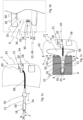
- Fig. 1a shows an example of a device 1 according to the invention.
- the device 1 according to the invention is preferably designed to record one or more vital parameters. Vital parameters are considered to be, for example, the core body temperature, the oxygen saturation of the blood or the pulse rate.
- the device 1 can thus alternatively be referred to as a device for recording vital parameters or alternatively as a pulse rate recording device or as an oxygen saturation recording device or as a core body temperature recording device.
- the device 1 preferably has several parts that can be detachably coupled to one another, namely an elongated insertion part 12 and a cover 62.
- the elongated insertion part 12 can preferably be connected to one another by means of a coupling device 60, in particular a plug connection, via which signals and/or data and/or power can be transmitted particularly preferably.
- a coupling device 60 in particular a plug connection
- the elongated insertion part 12 and the cover can be permanently connected to one another.
- the elongated insertion portion 12 is designed to be inserted into an ear canal of a living being 4 (cf. Fig. 1c ), in particular people, and has at least one sensor device, in particular an optical sensor device 2 and/or a temperature sensor 18.
- the optical sensor device 2 is preferably arranged on a front side 22 (cf. Fig. 1b ) of the elongate insertion portion 12.
- the front side 22 is preferably aligned substantially orthogonally to the longitudinal extension direction L of the elongate insertion portion 12.
- the front side 22 forms at least a part or a majority or a complete end 48 (cf. Fig. 1b ) of the elongated insertion portion 12.
- the end formed by the front side 22 can also be referred to as the inner end 48, since it extends the part in the longitudinal direction L of the elongated insertion portion 12 furthest into the auditory canal 14 of the ear 17 (cf. Fig. 1c ) of the living being 4 ( Fig. 1c ) insertable portion of the elongated insertion portion 12.
- the optical sensor device 2 preferably has a radiation source 6 and a radiation detector 8 for detecting radiation 7 emitted by the radiation source 6.
- the radiation source 6 and the radiation detector 8 are particularly preferably arranged next to one another, in particular at a distance of less than 5 mm or preferably less than 4 mm or particularly preferably less than 3 mm from one another.
- a radiation barrier 26 can be provided or formed between the radiation source 6 and the radiation detector 8.
- the radiation barrier can, for example, consist of the same material as the substrate 10 (cf. Fig. 1b ).
- the radiation barrier 28 is not permeable at least to radiation from the radiation source 6.
- the optical sensor device 2 preferably has at least one illuminant 28 and preferably two or more than two illuminants 28 and 30 and particularly preferably three or more than three illuminants 28, 30 and 31 (cf. Fig. 1b ).
- the first illuminant 28 of the radiation source 6 can emit radiation with wavelengths in the range of 860 nm and 900 nm, in particular in the range of 875 nm and 885 nm and preferably 880 nm.
- Another or second illuminant 30 of the radiation source 6 is preferably designed to emit radiation with wavelengths in the range of 620 nm and 700 nm, in particular in the range of 655 nm and 665 nm and preferably 660 nm.
- the radiation source 6 can have at least one third illuminant 31, wherein the third illuminant 31 can emit radiation in the range of 480 nm and 580 nm and preferably in a range of 510 nm and 545 nm and particularly preferably in a range of 520-535 nm.
- the light source designated as the third light source 31 is understood as the first light source or as the second light source.
- the first light source 29 can thus alternatively be understood as the second or third light source.
- the radiation detector 8 for detecting radiation 7 from the radiation source 6 is thus configured to detect radiation from the first illuminant 28 and the second illuminant 30 and the third illuminant 31 and to convert it into data or analog signals.
- the temperature sensor 18 is preferably mounted on a side facing the front 22 (cf. Fig. 1b ) inclined surface of the elongated introduction portion 12. Furthermore, a capacitor 66, in particular for supplying the radiation source 6 and/or the radiation detector 8 and/or the temperature sensor 18 with electrical energy, can be arranged or formed on the substrate.
- the elongated insertion portion 12 preferably has a sealing element 50 for sealing an ear canal 14 (cf. Fig. 1c ).
- the sealing element 50 is preferably arranged permanently or replaceably on the elongated insertion part 12. Particularly preferably, the position of the sealing element 50 can be adjusted or moved in the longitudinal direction L of the elongated insertion part 12. Alternatively, however, it is also possible for the sealing element 50 to be arranged fixedly (but preferably replaceably) at a defined position.
- the reference numeral 68 designates a connecting element which is preferably connected by means of a coupling device 60, in particular a detachable plug connection or a detachable magnetic connection, to the evaluation part 20, which preferably has at least one microprocessor 21 for processing the vital parameter data and/or for controlling the sensor device 2 and/or the temperature sensor 18.
- Signals and/or data and/or electrical energy can be conducted between the sensor device 2 and/or the temperature sensor 18 and the evaluation part 20 by means of one or more line elements (not shown).
- the line element or the line elements preferably run inside the elongated insertion part 20 and inside the connecting element 68.
- the elongated insertion part 20 and the connecting element 68 can alternatively be designed as a continuous device or as a device with a common housing or enclosure, in particular as an elongated insertion part 20 with an external connecting section.
- the reference number 58 designates a display device, in particular for displaying information, in particular vital parameter results or changes in vital parameters or operating instructions.
- input means (not shown), in particular buttons and switches, can also be provided for entering control commands.
- the display device 58 is preferably designed as a touchscreen and thus enables the selection or control of functions in addition to the optical output of information.
- the device 1 can have an acoustic output device (not shown) for the acoustic output of information, in particular vital parameter results or changes in vital parameters or operating instructions.
- the evaluation part 20 preferably has a communication means or a communication device 64, in particular a communication device for wireless data exchange, in particular for data exchange via radio transmission, such as NFC or Bluetooth or WLAN or 3G, 4G, 5G or 6G, or is connected to such a communication device 64.
- Fig. 1b shows an enlarged view of the area of the eardrum 24 (cf. Fig. 1c ) part of the device 1.
- the elastically deformable material 34 preferably has or forms a recess, whereby the radiation 7 emitted by the lighting means 28, 30, 31 can be introduced into the living being 4 via the eardrum 24 and reflected radiation 7 can reach the radiation detector 8 without the radiation having to penetrate through non-biological material.
- the reference number 36 designates a recess, ie an area in the beam path of the radiation 7 that is not filled with the elastic material 34.
- the elastically deformable material 34 can deformable material 34 completely encloses the sensor device 2, in which case the elastically deformable material would have to be transparent to the radiation 7 emitted by the at least one illuminant and preferably by the illuminants.
- Fig. 1c shows schematically a device 1 according to the invention, wherein the elongated insertion part 12 is introduced into the auditory canal 14 of a living being 4.
- the elastically deformable part 34 contacts the auditory canal wall 15 and prevents, for example, sharp-edged parts of the elongated part 12 from coming into contact with the very sensitive auditory canal wall 15.
- the sensor device 2 is arranged at a distance A of less than 7 mm from the eardrum 24.
- the sealing element 50 is preferably arranged such that it is positioned in a portion 161 of the auditory canal 14 surrounded by tissue. Alternatively, however, the sealing element 50 can also be arranged such that it is positioned in a portion 16 of the auditory canal 14 surrounded by bone. As a result of the positioning of the sealing element 50, an air volume 52 which is located between the sealing element 50 and the eardrum 24 is separated from the environment 56.
- the Fig. 2a-2c show a non-claimed example of the device 1.
- the Fig. 2a-2c The device 1 shown essentially corresponds to the one in Fig. 1a-1c shown device 1, only the arrangement of the sensor device 2 and/or the temperature sensor 18 is different, whereby the same reference numerals are used for the same components and the above-mentioned explanations apply analogously.
- Fig. 2b It can be seen that the radiation source 6 is arranged on a top side 32 of a substrate 10 for emitting radiation 7 in the direction of an ear canal wall 15 (cf. Fig. 2c ), in particular in the radial direction of the insertion portion 12.
- the radiation detector 8 is also arranged or formed on the upper side 32 of the substrate 10 for detecting radiation 7 from the direction of the auditory canal wall 15 (cf. Fig. 2c ), in particular from the radial direction of the insertion portion 12.
- the substrate 10 is preferably designed as a PCB and a radiation barrier 26 is particularly preferably formed between the radiation source 6 and the radiation detector 8.
- the radiation source 6 can be designed as at least two lighting means 28, 30, in particular a first LED or OLED and a second LED or OLED, for emitting radiation 7 of different wavelengths.
- the elongated insertion portion 12 is preferably designed so that the optical sensor device 2 is in a portion 16 of the auditory canal 14 surrounded by bone and/or at a distance (B) of equal to or less than 12mm from the eardrum 24 (cf. Fig. 2c ), especially for Eardrum 24 of a defined auditory canal 14, in particular at a distance of between 7mm and 3mm from the tympanic membrane 24 (cf. Fig. 2c ) can be positioned.
- Fig. 3 shows a further example of a sensor head 70.
- the sensor head 70 is formed by the elongated insertion portion 12 and at least a portion of the connecting element 68.
- the reference numeral 38 designates a surface spaced apart from the substrate 10, via which the radiation 7 can be emitted.
- the surface 38 is spaced apart from the nearest substrate surface portion by a distance 40.
- the reference numeral 34 designates an elastic material which is used to protect the auditory canal 14 (cf. Fig. 1c or Fig. 2c ) is provided.
- the elastic material has a distance 42 to the nearest substrate surface portion in an area adjacent to the radiation source 6, in particular directly.
- the distance 42 is preferably equal to the distance 40 or the distance 42 is greater than the distance 40.
- the present disclosure thus generally relates to a device 1 for detecting at least two vital parameters, wherein this device 1 has an optical sensor device 2, an elongated insertion part 12 and an evaluation part 20.
- the optical sensor device 2 is preferably used to detect at least one vital parameter of a living being 4, in particular a human, wherein the optical sensor device 2 has a radiation source 6 for emitting radiation 7 and a radiation detector 8 for detecting radiation 7, wherein the radiation source 6 and the radiation detector 8 are particularly preferably arranged next to one another.
- the elongated insertion part 12 is preferably used for insertion into an ear canal 14 and for positioning the optical sensor device 2 in a part 16 of the ear canal 14 surrounded by bone.
- the optical sensor device 2 is preferably arranged on the elongated insertion part 12 or is a component thereof.
- a temperature sensor 18 for detecting the core body temperature is preferably arranged on the elongated insertion part 12 or is part of it.
- the evaluation part 20 is preferably coupled to the insertion part 12, in particular detachably coupled, wherein the evaluation part 20 and the optical sensor device 2 are at least temporarily connected to one another in terms of signaling, in particular in a coupled state.
- the temperature sensor 18 and/or the capacitor 66 is/are arranged or formed on a rear side 54 facing away from the top side 32.
- the temperature sensor 18 and/or the capacitor 66 is arranged or formed on the same side, ie, for example, on the top side 32, on which the sensor device 2 is also arranged or formed.
Landscapes
- Health & Medical Sciences (AREA)
- Life Sciences & Earth Sciences (AREA)
- Physics & Mathematics (AREA)
- General Health & Medical Sciences (AREA)
- Veterinary Medicine (AREA)
- Engineering & Computer Science (AREA)
- Biomedical Technology (AREA)
- Heart & Thoracic Surgery (AREA)
- Medical Informatics (AREA)
- Molecular Biology (AREA)
- Surgery (AREA)
- Animal Behavior & Ethology (AREA)
- Biophysics (AREA)
- Public Health (AREA)
- Pathology (AREA)
- Otolaryngology (AREA)
- Spectroscopy & Molecular Physics (AREA)
- Optics & Photonics (AREA)
- Measurement Of The Respiration, Hearing Ability, Form, And Blood Characteristics Of Living Organisms (AREA)
- Measuring And Recording Apparatus For Diagnosis (AREA)
- Cardiology (AREA)
- Physiology (AREA)
- Measuring Pulse, Heart Rate, Blood Pressure Or Blood Flow (AREA)
- General Physics & Mathematics (AREA)
- Pulmonology (AREA)
Description
- Die vorliegende Erfindung bezieht sich gemäß Anspruch 1 auf eine Vorrichtung zum Erfassen von Vitalparametern in einem Ohr eines Menschen und gemäß Anspruch 12 auf ein Verfahren zum Messen von Vitalparametern eines Menschen.
- Die Druckschrift
EP3020327A offenbart beispielsweise ein Ohrthermometer, welches bereits vorteilhafte Resultate liefert, da eine Abdichtung des Gehörgangs zur Umgebung bereits im Gehörgang vorgeschlagen wird, wodurch ein vorteilhaftes Klima im abgedichteten Bereich entsteht. Dennoch ist es wünschenswert noch genauere und vielfältigere Informationen über den Gesundheitszustand einer in Not geratenen Person zu erhalten. Weiter Vorrichtungen zum Erfassen von Vitalparametern im Ohr werden durch die DruckschriftenWO2017/015661A1 ,WO99/23941A1 DE102017007040A1 undWO2017/203251A1 offenbart. - Es ist somit die Aufgabe der vorliegenden Erfindung eine genauere Erfassung des Gesundheitszustandes einer in Not geratenen Person, insbesondere unterkühlten Person, zu ermöglichen.
- Die zuvor genannten Aufgabe wird erfindungsgemäß durch eine Vorrichtung zum Erfassen von zumindest einem und besonders bevorzugt zwei oder zumindest zwei Vitalparametern nach Anspruch 1 gelöst. Eine solche Vorrichtung weist bevorzugt zumindest auf: Eine optische Sensoreinrichtung zur Erfassung von mindestens einem Vitalparameter eines Lebewesens, wobei die optische Sensoreinrichtung eine Strahlungsquelle zum Emittieren von Strahlung und einen Strahlungsdetektor zum Detektieren von Strahlung aufweist, wobei die Strahlungsquelle und der Strahlungsdetektor nebeneinander, insbesondere auf einem PCB, angeordnet sind. Nebeneinander bedeutet hierbei, dass die Strahlungsquelle und der Strahlungsdetektor bevorzugt auf derselben Oberfläche und insbesondere in derselben Orientierung angeordnet sind. Weiterhin weist die Vorrichtung bevorzugt einen länglichen Einbringanteil zum Einbringen in einen Gehörgang und zum Positionieren der optischen Sensoreinrichtung in einem von Knochen umgebenen Anteil des Gehörgangs auf. Länglich bedeutet hierbei bevorzugt, dass die Erstreckung des Einbringanteils in seiner Längsrichtung ein Vielfaches größer ist als die Erstreckung in einer Richtung orthogonal zur Längsrichtung des Einbringanteils, insbesondere mindestens 3-mal solange oder mindestens 5mal solange oder mindestens 10mal solange oder z.B. bis zu 20-mal solange oder z.B. bis zu 50-mal solange ist. Die optische Sensoreinrichtung ist besonders bevorzugt an dem länglichen Einbringanteil angeordnet oder Bestandteil davon und wobei ein Temperatursensor zur Erfassung der Körperkerntemperatur an dem länglichen Einbringanteil angeordnet ist oder Bestandteil davon ist. Weiterhin ist ein mit dem Einbringanteil gekoppelter, insbesondere lösbar gekoppelter, Auswerteanteil vorgesehen, wobei der Auswerteanteil und die optische Sensoreinrichtung zumindest zeitweise, insbesondere in einem gekoppelten Zustand, signaltechnisch miteinander verbunden sind.
- Diese Lösung ist vorteilhaft, da durch die Anordnung der Strahlungsquelle neben dem Strahlungsdetektor eine sehr kompakte Bauform ermöglicht wird, wodurch die optische Sensoreinrichtung sehr tief im Gehörgang positionierbar ist. Die Positionierung im Bereich des Trommelfells hat den Vorteil, dass die Vitalparameter sehr genau erfassbar sind.
- Die Vorrichtung bzw. Sonde ist bevorzugt für die Verwendung bei Erwachsenen und Jugendlichen (>14 Jahre alt) geeignet. Ihre Abmessungen sind besonders bevorzugt für eine kranio-morphometrische Anatomie konzipiert, die zum Zeitpunkt der Anmeldung des vorliegenden Schutzrechts der Mehrheit der weißen kaukasischen/asiatischen Menschen entspricht, insbesondere einen darauf bezogenen definierten Gehörgang mit einer bevorzugt minimalen Länge von 12mm und einer bevorzugt maximalen Länge von 25mm.
- Weitere bevorzugte Ausführungsformen der vorliegenden Erfindung sind Gegenstand der nachfolgenden Beschreibungsteile und/oder der Unteransprüche.
- Die Strahlungsquelle ist gemäß der vorliegenden Erfindung auf einer Vorderseite eines Substrats zum Emittieren von Strahlung in Richtung eines Trommelfells, insbesondere in Verlängerungsrichtung des Einbringanteils, angeordnet oder ausgebildet und der Strahlungsdetektor ist besonders bevorzugt ebenfalls auf der Vorderseite des Substrats zum Detektieren von Strahlung aus Richtung des Trommelfells, insbesondere aus der Verlängerungsrichtung des Einbringanteils, angeordnet oder ausgebildet. Das Substrat ist besonders bevorzugt eine Leiterplatine bzw. ein Printed Circuit Board (PCB), wobei das PCB bevorzugt mittels Leitungen, insbesondere flexiblen Leitungen, wie z.B. Kabeln, zum Übermitteln der erfassten Signale und/oder Daten mit dem Auswerteanteil verbindbar oder verbunden ist. Bevorzugt ist zwischen der Strahlungsquelle und dem Strahlungsdetektor eine Strahlungsbarriere ausgebildet, wobei die Strahlungsquelle als zumindest zwei Leuchtmittel, insbesondere eine erste LED oder OLED und eine zweite LED oder OLED, zum Emittieren von Strahlung unterschiedlicher Wellenlängen ausgebildet ist. Als Strahlungsbarriere im Sinne der vorliegenden Erfindung wird eine Einrichtung verstanden, welche eine direkte Beleuchtung des Strahlungsdetektors mit Strahlung der Strahlungsquelle verhindert. Besonders bevorzugt ist die Strahlungsbarriere als wandartige Einrichtung oder Erhebung zwischen der Strahlungsquelle und dem Strahlungsdetektor ausgebildet. Bevorzugt besteht die Strahlungsbarriere z.B. aus Silizium. Diese Ausführungsform ist vorteilhaft, da die von der Strahlungsquelle emittierte Strahlung sehr gut vom Trommelfell und den dahinterliegenden Strukturen reflektiert wird, wodurch die Vitalparameter sehr genau erfasst werden können.
- Der längliche Einbringanteil ist gemäß einer weiteren bevorzugten Ausführungsform der vorliegenden Erfindung dazu eingerichtet, die optische Sensoreinrichtung in einem Abstand von gleich oder weniger als 7mm zum Trommelfell, insbesondere zum Trommelfell eines definierten Gehörgangs, zu positionieren, insbesondere in einem Abstand zwischen 7mm und 3mm zum Trommelfell zu positionieren. Zusätzlich oder alternativ kann der längliche Einbringanteil eine Länge zwischen 12mm und 25mm, insbesondere zwischen 14mm und 23mm und besonders bevorzugt zwischen 16mm und 21mm und höchst bevorzugt von 18mm bzw. im Wesentlichen 18mm oder ca. 18mm oder genau 18mm, aufweisen. Beide Ausführungsformen bzw. Definitionen des Einbringanteil sind vorteilhaft, da dadurch der Abstand der optischen Sensoreinrichtung zum Trommelfell vorteilhaft vorgegeben wird.
- Die Strahlungsquelle ist gemäß einer nicht beanspruchten Ausführungsform auf einer Oberseite eines Substrats zum Emittieren von Strahlung in Richtung einer Gehörgangwandung, insbesondere in radialer Richtung des Einbringanteils, angeordnet oder ausgebildet und der Strahlungsdetektor ist bevorzugt ebenfalls auf der Oberseite des Substrats zum Detektieren von Strahlung aus Richtung der Gehörgangwandung, insbesondere aus radialer Richtung des Einbringanteils, angeordnet oder ausgebildet. Die Strahlungsquelle und der Strahlungsdetektor sind bevorzugt in dieselbe Richtung orientiert, insbesondere derart, dass von der Strahlungsquelle emittierte Strahlung infolge von Reflexion durch den Strahlungsdetektor erfassbar ist. Das Substrat ist besonders bevorzugt eine Leiterplatine bzw. ein Printed Circuit Board (PCB), wobei das PCB bevorzugt mittels Leitungen, insbesondere flexiblen Leitungen, wie z.B. Kabeln, zum Übermitteln der erfassten Signale und/oder Daten mit dem Auswerteanteil verbindbar oder verbunden ist. Zwischen der Strahlungsquelle und dem Strahlungsdetektor ist bevorzugt eine Strahlungsbarriere ausgebildet. Besonders bevorzugt ist die Strahlungsbarriere als wandartige Einrichtung oder Erhebung zwischen der Strahlungsquelle und dem Strahlungsdetektor ausgebildet. Bevorzugt besteht die Strahlungsbarriere z.B. aus Silizium. Die Strahlungsquelle ist bevorzugt als zumindest zwei Leuchtmittel, insbesondere eine erste LED oder OLED und eine zweite LED oder OLED, zum Emittieren von Strahlung unterschiedlicher Wellenlängen ausgebildet. Diese Ausführungsform ist vorteilhaft, da die Strahlungsquelle und der Strahlungsdetektor sehr nah am Trommelfell in Richtung der Gehörgangswandung ausgerichtet sind, wodurch sehr präzise Vitalparameter erfassbar sind.
- Der längliche Einbringanteil ist gemäß einer nicht beanspruchten Ausführungsform dazu eingerichtet, die optische Sensoreinrichtung in einem von Knochen umgebenen Anteil des Gehörgangs und/oder in einem Abstand von gleich oder weniger als 12mm zum Trommelfell, insbesondere zum Trommelfell eines definierten Gehörgangs, zu positionieren, insbesondere in einem Abstand zwischen 7mm und 3mm zum Trommelfell zu positionieren. Zusätzlich oder alternativ weist der längliche Einbringanteil eine Länge zwischen 12mm und 25mm, insbesondere zwischen 14mm und 23mm und besonders bevorzugt zwischen 16mm und 21mm und höchst bevorzugt von 18mm bzw. im Wesentlichen 18mm oder ca. 18mm oder genau 18mm, auf. Beide Ausführungsformen bzw. Definitionen des Einbringanteil sind vorteilhaft, da dadurch die Positionierung der optischen Sensoreinrichtung sehr nah zum Trommelfell beabstandet vorteilhaft vorgegeben wird.
- Durch ein Leuchtmittel bzw. ein erstes Leuchtmittel der Strahlungsquelle ist gemäß einer weiteren bevorzugten Ausführungsform der vorliegenden Erfindung Strahlung mit Wellenlängen im Bereich von 860nm und 900nm, insbesondere im Bereich von 875nm und 885nm und bevorzugt von 880nm, emittierbar. Zusätzlich oder alternativ ist durch ein Leuchtmittel bzw. ein anderes Leuchtmittel oder ein weiteres Leuchtmittel der Strahlungsquelle gemäß einer weiteren bevorzugten Ausführungsform der vorliegenden Erfindung Strahlung mit Wellenlängen im Bereich von 620nm und 700nm, insbesondere im Bereich von 655nm und 665nm und bevorzugt von 660nm, emittierbar. Zusätzlich oder alternativ weist die Strahlungsquelle gemäß einer weiteren bevorzugten Ausführungsform der vorliegenden Erfindung ein Leuchtmittel bzw. ein weiteres Leuchtmittel bzw. ein drittes Leuchtmittel auf, wobei durch das dritte Leuchtmittel Strahlung im Bereich von 480nm und 580nm und bevorzugt in einem Bereich von 510nm und 545nm und besonders bevorzugt in einem Bereich von 520-535 nm emittierbar ist. Der Strahlungsdetektor ist besonders bevorzugt zum Detektieren von Strahlung des Leuchtmittels, des anderen Leuchtmittels und des dritten Leuchtmittels konfiguriert. Diese Ausführungsform ist vorteilhaft, da mittels der Strahlung des ersten Leuchtmittels und/oder der Strahlung des zweiten Leuchtmittels ein definierter Vitalparameter, insbesondere die Sauerstoffsättigung, erfassbar ist. Die Ausführungsform ist ferner vorteilhaft, da zusätzlich oder alternativ mittels dem Leuchtmittel bzw. dem dritten Leuchtmittel die Pulsrate erfassbar ist.
- Die Strahlungsquelle und/oder der Strahlungsdetektor sind gemäß einer weiteren bevorzugten Ausführungsform der vorliegenden Erfindung von einem für die Strahlung der Strahlungsquelle transparentem und elastisch verformbaren Material, insbesondere einem Polymermaterial, umschlossen, insbesondere darin eingebettet. Diese Ausführungsform ist vorteilhaft, da durch das elastisch verformbare Material die sehr verletzlichen Bestandteile des Gehörgangs geschützt sind. Weiterhin wird durch das transparente Material ermöglich, dass die optische Erfassung des bzw. der Vitalparameter bewirkbar ist.
- Das Substrat ist gemäß einer weiteren bevorzugten Ausführungsform der vorliegenden Erfindung mehrheitlich von einem elastisch verformbaren Material, insbesondere einem Polymermaterial, umschlossen, wobei das verformbare Material zumindest eine Ausnehmung ausbildet, wobei in der Ausnehmung die Strahlungsquelle und/oder der Strahlungsdetektor angeordnet sind. Die Ausführungsform ist vorteilhaft, da die Transparenzanforderung an das verformbare Material nicht gegeben ist, wodurch dieses kostengünstiger ausgewählt werden kann, insbesondere wenn das verformbare Material alternativ für mehrere Wellenlängenbereiche transparent sein müsste.
- Eine Oberfläche der Strahlungsquelle, über welche die Strahlung der Strahlungsquelle emittierbar ist, ist gemäß einer weiteren bevorzugten Ausführungsform der vorliegenden Erfindung in einem ersten Abstand zum Substrat angeordnet, und wobei eine äußere Oberfläche des verformbaren Materials zumindest in dem die Ausnehmung umgebenen Bereich einen zweiten Abstand zum Substrat aufweist, wobei der zweite Abstand entweder gleich groß oder größer als der erste Abstand ist. Diese Ausführungsform ist vorteilhaft, da dadurch der Mindestabstand zwischen der Sensoreinrichtung und der Gehörgangsoberfläche definiert ist.
- Der in den Gehörgang einbringbare längliche Einbringanteil bildet gemäß der vorliegenden Erfindung in seiner Längsrichtung ein inneres Ende aus und wobei der längliche Einbringanteil ein oder mindestens ein Abdichtungselement zum Verschließen des Gehörgangs aufweist oder ausbildet, wobei der Temperatursensor zwischen dem inneren Ende und dem Abdichtungselement angeordnet oder ausgebildet ist. Diese Ausführungsform ist vorteilhaft, da der Temperatursensor in einem Bereich anordenbar ist, in dem die Körperkerntemperatur erfassbar ist.
- Die Anordnung des Temperatursensors zur Bestimmung der Körperkerntemperatur ist gemäß einer bevorzugten Ausführungsform der vorliegenden Erfindung derart konfiguriert, dass der Temperatursensor in einem Abstand von 9mm und 2mm oder in einem Abstand von weniger als 9mm, insbesondere weniger als 7mm oder zwischen 7mm und 2mm, und/oder in einem Abstand von mindestens 0,1mm vom Trommelfell beabstandet anordenbar ist, und wobei der Temperatursensor zur Bestimmung der Lufttemperatur eines zwischen dem Abdichtungselement und dem inneren Ende vorhandenen Luftvolumens eingerichtet ist. Diese Ausführungsform ist vorteilhaft, da durch das Abdichtungselement ein Bereich des Gehörgangs von der Umgebung abgegrenzt wird und sich in diesem Bereich die vorhandene Luft somit sehr schnell auf das Niveau der Körperkerntemperatur erwärmen lässt. Dadurch sind innerhalb kurzer Zeit sehr genaue Temperaturmessungen möglich.
- Der Auswerteanteil und der Temperatursensor sind gemäß einer bevorzugten Ausführungsform der vorliegenden Erfindung zumindest zeitweise, insbesondere im gekoppelten Zustand, signaltechnisch miteinander verbunden sind. Der Temperatursensor ist bevorzugt ein von einem optischen Sensor verschiedener Sensor. Der Temperatursensor ist besonders bevorzugt ein Thermistor, wobei der Temperatursensor bevorzugt auf einer Rückseite des Substrats bzw. PCB angeordnet oder ausgebildet ist. Die Rückseite ist bevorzugt parallel oder bevorzugt abschnittsweise parallel zur Oberseite ausgebildet. Diese Lösung ist vorteilhaft, da mit einem sehr kleinen PCB mehrere Funktionsgruppen sehr nah am Trommelfell bzw. sehr tief im Gehörgang, insbesondere in inneren von Knochen umgebenen Gehörgangsanteil anordenbar sind.
- Die oben genannte Aufgabe wird ebenfalls durch ein Verfahren gemäß Anspruch 10 zum Messen von Vitalparametern eines Menschen gelöst. Das erfindungsgemäße Verfahren weist bevorzugt mindestens die Schritte auf: Bereitstellen einer Vorrichtung zum Erfassen von zumindest zwei Vitalparametern, insbesondere eine erfindungsgemäße Vorrichtung, Einbringen des länglichen Einbringanteil in einem Gehörgang eines Menschen, Positionieren der optische Sensoreinrichtung in einem Abstand von 7mm oder von weniger als 7mm zum Trommelfell, Positionieren des Temperatursensors in einem Abstand von 16mm oder von weniger als 16mm zum Trommelfell, Abgrenzen eines Luft beinhaltenden Volumenanteils des Gehörgangs mittels eines Abdichtungselements des länglichen Einbringanteil gegenüber der Umgebung, Erzeugen von Temperaturdaten, insbesondere Kerntemperaturdaten, wobei die Temperaturdaten die Temperatur der im abgegrenzten Volumenanteil befindlichen Luft nach einer definierten Mindestdauer nachdem der Volumenanteil gegenüber der Umgebung abgegrenzt wurde repräsentieren, wobei die Temperaturdaten von dem Temperatursensor erzeugt werden oder aus analogen Sensorsignalen des Temperatursensors abgeleitet werden nachdem der Temperatursensor die Temperatur der im abgegrenzten Volumenanteil befindlichen Luft erfasst hat, Erzeugen von Vitalparameterdaten, wobei die Vitalparameterdaten von der optischen Sensoreinrichtung erzeugt werden oder aus analogen Sensorsignaldaten der optischen Sensoreinrichtung abgeleitet werden, wobei die Vitalparameterdaten zumindest einen Vitalparameter des Menschen repräsentieren, wobei die optische Sensoreinrichtung den zumindest einen Vitalparameter erfasst hat, Ansteuern einer Anzeigeeinrichtung in Abhängigkeit der Temperaturdaten und/oder der Vitalparameterdaten. Diese Lösung ist vorteilhaft, da durch die Anordnung der Sensoreinrichtung in unmittelbarer Nähe zum Trommelfell sehr präzise ein Vitalparameter oder eine Vielzahl an Vitalparametern erfasst werden kann.
- Die optische Sensoreinrichtung wird gemäß einer weiteren bevorzugten Ausführungsform der vorliegenden Erfindung in einem Abstand von 6mm oder von weniger als 6mm zum Trommelfell positioniert, und der Temperatursensor wird bevorzugt in einem Abstand von 16mm oder von weniger als 16mm zum Trommelfell positioniert und der Auswerteanteil und der längliche Einbringanteil werden bevorzugt über eine Steckverbindung zur Erzeugung einer Datenverbindung, insbesondere Daten- und Energieverbindung, miteinander verbunden, wobei die optische Sensoreinrichtung die Vitalparameterdaten oder Vitalparametersignale an den Auswerteanteil übermittelt und wobei der Temperatursensor die Temperaturdaten oder Temperatursignale an den Auswerteanteil übermittelt. Zusätzlich oder alternativ kann die Vorrichtung zum Erfassen von zumindest zwei Vitalparametern, insbesondere der Sauerstoffsättigung und der Pulsfrequenz, mit einer Abdeckung zum vollständigen Abdecken des Ohrs und bevorzugt zur zumindest teilweisen und bevorzugt vollständigen Abdeckung des Mastoides verbunden werden, wobei die Abdeckung die Anzeigeeinrichtung, insbesondere ein Display, aufweist, wobei die Anzeigeeinrichtung in Abhängigkeit der Vitalparameterdaten und/oder Kerntemperaturdaten angesteuert wird. Zusätzlich oder alternativ kann der Auswerteanteil eine Kommunikationsschnittstelle zum kabellosen Datenaustausch aufweisen, wobei zwischen der Kommunikationsschnittstelle und einem mobilen Endgerät eine Datenverbindung zum Übermitteln der Vitalparameterdaten und/oder der Temperaturdaten oder zum Übermitteln von durch den Auswerteanteil erzeugten Auswertedaten aufgebaut wird, wobei die Auswertedaten aus den Vitalparameterdaten und/oder den Temperaturdaten erzeugt werden.
- Einzelne oder alle Darstellungen der im Nachfolgenden beschriebenen Figuren sind bevorzugt als Konstruktionszeichnungen anzusehen, d.h. die sich aus der bzw. den Figuren ergebenden Abmessungen, Proportionen, Funktionszusammenhänge und/oder Anordnungen entsprechen bevorzugt genau oder bevorzugt im Wesentlichen denen der erfindungsgemäßen Vorrichtung/en bzw. des erfindungsgemäßen Produkts bzw. des erfindungsgemäßen Systems bzw. visualisieren im Wesentlichen oder genau Schritte des erfindungsgemäßen Verfahrens bzw. der erfindungsgemäßen Verfahren.
- Darin zeigt:
- Fig. 1a
- eine schematische Ansicht einer beispielhaften erfindungsgemäßen Vorrichtung zur Einbringung in einen Gehörgang eines Menschen;
- Fig. 1b
- eine schematische und vergrößerte Ansicht der in
Fig. 1a lediglich skizzierten Sensoreinrichtung; - Fig. 1c
- eine schematische Ansicht der beispielhaften erfindungsgemäßen Vorrichtung nach
Fig. 1a eingesetzt in den Gehörgang eines Menschen; - Fig. 2a
- eine schematische Ansicht einer weiteren nicht beanspruchten Vorrichtung zum Einsetzen in den Gehörgang eines Menschen;
- Fig. 2b
- eine schematische und vergrößerte Ansicht der in
Fig. 2a lediglich skizzierten Sensoreinrichtung; - Fig. 2c
- eine schematische Ansicht der beispielhaften erfindungsgemäßen Vorrichtung nach
Fig. 2a eingesetzt in den Gehörgang eines Menschen; und - Fig. 3
- eine schematische Ansicht eines alternativen Sensorkopfes einer nicht beanspruchten Vorrichtung.
-
Fig. 1a zeigt ein Beispiel einer erfindungsgemäßen Vorrichtung 1. Die erfindungsgemäße Vorrichtung 1 ist dabei bevorzugt zum Erfassen eines oder mehrerer Vitalparameter ausgebildet. Als Vitalparameter wird hierbei beispielsweise die Körperkerntemperatur, die Sauerstoffsättigung des Blutes oder die Pulsfrequenz angesehen. Die Vorrichtung 1 kann somit alternativ als Vorrichtung zur Erfassung von Vitalparametern oder alternativ als Pulsfrequenzerfassungsvorrichtung oder als Sauerstoffsättigungserfassungsvorrichtung oder als Körperkerntemperaturerfassungsvorrichtung bezeichnet werden. Bevorzugt weist die Vorrichtung 1 mehrere miteinander lösbar koppelbare Anteile, nämlich einen länglichen Einbringanteil 12 und eine Abdeckung 62 auf. Der längliche Einbringanteil 12 ist dabei bevorzugt mittels einer Kopplungseinrichtung 60, insbesondere einer Steckverbindung, über welche besonders bevorzugt Signale und/oder Daten und/oder Strom übertragbar ist miteinander verbindbar. Es ist jedoch alternativ auch möglich, dass der längliche Einbringanteil 12 und die Abdeckung unlösbar miteinander verbunden sind. - Der längliche Einbringanteil 12 ist zur Einbringung in einen Gehörgang eines Lebewesens 4 (vgl.
Fig. 1c ), insbesondere Menschen, gestaltet und weist zumindest eine Sensoreinrichtung, insbesondere eine optische Sensoreinrichtung 2 und/oder einen Temperatursensor 18, auf. Die optische Sensoreinrichtung 2 ist bevorzugt auf einer Vorderseite 22 (vgl.Fig. 1b ) des länglichen Einbringanteils 12 angeordnet oder ausgebildet. Die Vorderseite 22 ist bevorzugt im Wesentlichen orthogonal zur Längserstreckungsrichtung L des länglichen Einbringanteils 12 ausgerichtet. Bevorzugt bildet die Vorderseite 22 zumindest einen Teil oder mehrheitlich oder vollständig ein Ende 48 (vgl.Fig. 1b ) des länglichen Einbringanteils 12 auf. Das von der Vorderseite 22 ausgebildete Ende kann auch als inneres Ende 48 bezeichnet werden, da es den in Längsrichtung L des länglichen Einbringanteil 12 am weitesten in den Gehörgang 14 des Ohrs 17 (vgl.Fig. 1c ) des Lebewesens 4 (Fig. 1c ) einbringbaren Anteil des länglichen Einbringanteils 12 ausbildet bzw. darstellt. Die optische Sensoreinrichtung 2 weist bevorzugt eine Strahlungsquelle 6 und einen Strahlungsdetektor 8 zum Detektieren von Strahlung 7, welche von der Strahlungsquelle 6 emittiert wurde auf. Besonders bevorzugt sind die Strahlungsquelle 6 und der Strahlungsdetektor 8 nebeneinander, insbesondere in einem Abstand von weniger als 5mm oder bevorzugt weniger als 4mm oder besonders bevorzugt weniger als 3mm zueinander angeordnet. Es ist hierbei möglich, dass eine Strahlungsbarriere 26 zwischen der Strahlungsquelle 6 und dem Strahlungsdetektor 8 vorgesehen bzw. ausgebildet ist. Die Strahlungsbarriere kann beispielsweise aus demselben Material bestehen, aus dem auch das Substrat 10 (vgl.Fig. 1b ) besteht. Bevorzugt ist die Strahlungsbarriere 28 jedoch zumindest für Strahlung der Strahlungsquelle 6 nicht durchlässig. - Die optische Sensoreinrichtung 2 weist bevorzugt zumindest ein Leuchtmittel 28 und bevorzugt zwei oder mehr als zwei Leuchtmittel 28 und 30 und besonders bevorzugt drei oder mehr als drei Leuchtmittel 28, 30 und 31 (vgl.
Fig. 1b ) auf. Bevorzugt kann durch das erste Leuchtmittel 28 der Strahlungsquelle 6 Strahlung mit Wellenlängen im Bereich von 860nm und 900nm, insbesondere im Bereich von 875nm und 885nm und bevorzugt von 880nm, emittierbar sein. Ein anderes bzw. zweites Leuchtmittel 30 der Strahlungsquelle 6 ist bevorzugt zum emittieren von Strahlung mit Wellenlängen im Bereich von 620nm und 700nm, insbesondere im Bereich von 655nm und 665nm und bevorzugt von 660nm, ausgebildet. Bevorzugt kann die Strahlungsquelle 6 zumindest ein drittes Leuchtmittel 31 aufweisen, wobei durch das dritte Leuchtmittel 31 Strahlung im Bereich von 480nm und 580nm und bevorzugt in einem Bereich von 510nm und 545nm und besonders bevorzugt in einem Bereich von 520-535 nm emittierbar ist. Es ist hierbei selbstverständlich möglich, dass -je nach erforderlichen Vitalparametern - das als drittes Leuchtmittel 31 bezeichnete Leuchtmittel als erstes Leuchtmittel oder als zweites Leuchtmittel verstanden wird. Ebenso kann für das zweite Leuchtmittel 30 gelten, dass es alternativ als erstes oder drittes Leuchtmittel verstanden werden kann. Das erste Leuchtmittel 29 kann somit alternativ als zweites oder drittes Leuchtmittel verstanden werden. - Der Strahlungsdetektor 8 zum Detektieren von Strahlung 7 der Strahlungsquelle 6 ist somit konfiguriert Strahlung des ersten Leuchtmittels 28 und des zweiten Leuchtmittels 30 und des dritten Leuchtmittels 31 zu erfassen und in Daten oder analoge Signale zu überführen.
- Der Temperatursensor 18 ist bevorzugt auf einer zur Vorderseite 22 (vgl.
Fig. 1b ) geneigten Oberfläche des länglichen Einbringanteils 12 angeordnet oder ausgebildet. Weiterhin kann ein Kondensator 66, insbesondere zur Versorgung der Strahlungsquelle 6 und/oder des Strahlungsdetektors 8 und/oder des Temperatursensors 18 mit elektrischer Energie, auf dem Substrat angeordnet oder ausgebildet sein. - Ferner weist der längliche Einbringanteil 12 bevorzugt ein Abdichtungselement 50 zum Abdichten eines Gehörgangs 14 (vgl.
Fig. 1c ) auf. Das Abdichtungselement 50 ist dabei bevorzugt dauerhaft oder austauschbar am länglichen Einbringanteil 12 angeordnet. Besonders bevorzugt lässt sich die Position des Abdichtungselements 50 in Längsrichtung L des längliche Einbringanteils 12 einstellen oder verschieben. Alternativ ist es jedoch auch möglich, dass das Abdichtungselement 50 an einer definierten Position fest (jedoch bevorzugt austauschbar) angeordnet ist. - Das Bezugszeichen 68 kennzeichnet ein Verbindungselement, welches bevorzugt mittels einer Kopplungseinrichtung 60, insbesondere einer lösbaren Steckverbindung oder einer lösbaren magnetischen Verbindung, mit dem Auswerteanteil 20, welcher bevorzugt über zumindest einen Microprozessor 21 zum Aufbereiten der Vitalparameterdaten und/oder zum Ansteuern der Sensoreinrichtung 2 und/oder dem Temperatursensor 18 verfügt, verbunden ist.
- Signale und/oder Daten und/oder elektrische Energie ist dabei mittels einem oder mehreren Leitungselement/en (nicht gezeigt) zwischen der Sensoreinrichtung 2 und/oder dem Temperatursensor 18 und dem Auswertanteil 20 leitbar. Das Leitungselement oder die Leitungselemente verlaufen dabei bevorzugt im Inneren des länglichen Einbringanteils 20 sowie im Inneren des Verbindungselements 68. Der längliche Einbringanteil 20 und das Verbindungselement 68 können alternativ als eine kontinuierliche Einrichtung bzw. als Einrichtung mit einem gemeinsamen Gehäuse oder Einhausung, insbesondere als länglicher Einbringanteil 20 mit äußerem Verbindungsabschnitt, ausgeführt sein. Das Bezugszeichen 58 kennzeichnet eine Anzeigeeinrichtung, insbesondere zum Anzeigen von Informationen, insbesondere Vitalparameterergebnisse oder Veränderungen von Vitalparametern oder Bedienanweisungen. Weiterhin können auch Eingabemittel (nicht gezeigt), insbesondere Taster und Schalter, zum Eingeben von Steuerbefehlen vorgesehen sein. Bevorzugt ist die Anzeigeeinrichtung 58 als Touchscreen ausgebildet und ermöglich somit neben der optischen Ausgabe von Information auch die Auswahl oder Ansteuerung von Funktionen. Ferner kann die Vorrichtung 1 eine akustische Ausgabeeinrichtung (nicht gezeigt) zur akustischen Ausgabe von Informationen, insbesondere Vitalparameterergebnisse oder Veränderungen von Vitalparametern oder Bedienanweisungen, aufweisen. Weiterhin weist der Auswerteanteil 20 bevorzugt ein Kommunikationsmittel bzw. eine Kommunikationseinrichtung 64, insbesondere eine Kommunikationseinrichtung zum kabellosen Datenaustausch, insbesondere zum Datenaustausch per Funkübertragung, wie z.B. NFC oder Bluetooth oder WLAN oder 3G, 4G, 5G oder 6G, auf oder ist mit einer solchen Kommunikationseinrichtung 64 verbunden.
-
Fig. 1b zeigt eine vergrößerte Darstellung des im Bereich des Trommelfells 24 (vgl.Fig. 1c ) anordenbaren Anteils der Vorrichtung 1. Es ist erkennbar, dass das elastisch verformbare Material 34 bevorzugt eine Ausnehmung aufweist oder ausbildet, wobei die Strahlung 7, welche von den Leuchtmitteln 28, 30, 31 emittiert wird, über das Trommelfell 24 in das Lebewesen 4 einleitbar ist und reflektierte Strahlung 7 zum Strahlungsdetektor 8 gelangen kann, ohne dass die Strahlung durch nichtbiologisches Material hindurchdringen muss. Das Bezugszeichen 36 kennzeichnet hierbei eine Ausnehmung, d.h. einen nicht vom elastischen Material 34 gefüllten Bereich im Strahlengang der Strahlung 7. Alternativ kann das elastisch verformbare Material 34 die Sensoreinrichtung 2 vollständig einhausen, wobei in diesem Fall das elastisch verformbare Material für die von dem mindestens einen Leuchtmittel und bevorzugt von den Leuchtmitteln emittierte Strahlung 7 transparent sein müsste. -
Fig. 1c zeigt schematisch eine erfindungsgemäße Vorrichtung 1, wobei der längliche Einbringanteil 12 in den Gehörgang 14 eines Lebewesens 4 eingebracht ist. Der elastisch verformbare Anteil 34 kontaktiert dabei die Gehörgangswandung 15 und verhindert z.B., dass scharfkantige Anteile des länglichen Anteils 12 mit der sehr empfindlichen Gehörgangswandung 15 in Kontakt kommt. - Die Sensoreinrichtung 2 ist in der gezeigten Anordnung in einem Abstand A von weniger als 7mm zum Trommelfell 24 beabstandet angeordnet.
- Das Abdichtungselement 50 ist bevorzugt derart angeordnet, dass in einem von Gewebe umgebenen Anteil 161 des Gehörgangs 14 positioniert wird. Alternativ kann das Abdichtelement 50 jedoch auch derart angeordnet sein, dass es in einem von Knochen umgebenen Anteil 16 des Gehörgangs 14 positioniert wird. Infolge der Positionierung des Abdichtungselements 50 wird ein Luftvolumen 52, welches sich zwischen dem Abdichtungselement 50 und dem Trommelfell 24 befindet von der Umgebung 56 abgegrenzt.
- Die
Fig. 2a-2c zeigen ein nicht beanspruchtes Beispiel der Vorrichtung 1. Die in denFig. 2a-2c gezeigte Vorrichtung 1 stimmt im Wesentlichen mit der inFig. 1a-1c gezeigten Vorrichtung 1 überein, wobei lediglich die Anordnung der Sensoreinrichtung 2 und/oder des Temperatursensors 18 verschieden ist, wodurch für dieselben Komponenten dieselben Bezugszeichen verwendet werden und die zuvor genannten Erläuterungen analog gelten. Es ist hierbei z.B.Fig. 2b entnehmbar, dass die Strahlungsquelle 6 auf einer Oberseite 32 eines Substrats 10 zum Emittieren von Strahlung 7 in Richtung einer Gehörgangwandung 15 (vgl.Fig. 2c ), insbesondere in radialer Richtung des Einbringanteils 12, angeordnet oder ausgebildet ist. Der Strahlungsdetektor 8 ist ebenfalls auf der Oberseite 32 des Substrats 10 zum Detektieren von Strahlung 7 aus Richtung der Gehörgangwandung 15 (vgl.Fig. 2c ), insbesondere aus radialer Richtung des Einbringanteils 12, angeordnet oder ausgebildet. Das Substrat 10 ist bevorzugt als ein PCB ausgeführt und zwischen der Strahlungsquelle 6 und dem Strahlungsdetektor 8 ist besonders bevorzugt eine Strahlungsbarriere 26 ausgebildet ist. Die Strahlungsquelle 6 kann dabei als zumindest zwei Leuchtmittel 28, 30, insbesondere eine erste LED oder OLED und eine zweite LED oder OLED, zum Emittieren von Strahlung 7 unterschiedlicher Wellenlängen ausgebildet sein. Der längliche Einbringanteil 12 ist bevorzugt dazu eingerichtet, dass die optische Sensoreinrichtung 2 in einem von Knochen umgebenen Anteil 16 des Gehörgangs 14 und/oder in einem Abstand (B) von gleich oder weniger als 12mm zum Trommelfell 24 (vgl.Fig. 2c ), insbesondere zum Trommelfell 24 eines definierten Gehörgangs 14, positionierbar ist, insbesondere in einem Abstand zwischen 7mm und 3mm zum Trommelfell 24 (vgl.Fig. 2c ) positionierbar ist.Fig. 3 zeigt ein weiteres Beispiel eines Sensorkopfes 70. Der Sensorkopf 70 wird dabei durch den länglichen Einbringanteil 12 und zumindest einen Anteil des Verbindungselements 68 ausgebildet. Das Bezugszeichen 38 kennzeichnet dabei eine vom Substrat 10 beabstandete Oberfläche, über welche die Strahlung 7 emittierbar ist. Die Oberfläche 38 ist dabei in einem Abstand 40 zum nächstliegenden Substratoberflächenanteil beabstandet. Das Bezugszeichen 34 kennzeichnet ein elastisches Material, welches zum Schutz des Gehörgangs 14 (vgl.Fig. 1c oderFig. 2c ) vorgesehen ist. Das elastische Material hat in einem an die Strahlungsquelle 6, insbesondere unmittelbar, angrenzenden Bereich einen Abstand 42 zum nächstliegenden Substratoberflächenanteil. Der Abstand 42 ist bevorzugt gleich dem Abstand 40 oder der Abstand 42 ist größer als der Abstand 40. - Die vorliegende Offenbarung bezieht sich somit allgemein auf eine Vorrichtung 1 zum Erfassen von zumindest zwei Vitalparametern, wobei diese Vorrichtung 1 eine optische Sensoreinrichtung 2, einen länglichen Einbringanteil 12 und einen Auswerteanteil 20 aufweist. Die optische Sensoreinrichtung 2 dient bevorzugt zur Erfassung von mindestens einem Vitalparameter eines Lebewesens 4, insbesondere Menschen, wobei die optische Sensoreinrichtung 2 eine Strahlungsquelle 6 zum Emittieren von Strahlung 7 und einen Strahlungsdetektor 8 zum Detektieren von Strahlung 7 aufweist, wobei die Strahlungsquelle 6 und der Strahlungsdetektor 8 besonders bevorzugt nebeneinander angeordnet sind. Der längliche Einbringanteil 12 dient bevorzugt zum Einbringen in einen Gehörgang 14 und zum Positionieren der optischen Sensoreinrichtung 2 in einem von Knochen umgebenen Anteil 16 des Gehörgangs 14. Die optische Sensoreinrichtung 2 ist bevorzugt an dem länglichen Einbringanteil 12 angeordnet oder ist Bestandteil davon. Ein Temperatursensor 18 zur Erfassung der Körperkerntemperatur ist bevorzugt an dem länglichen Einbringanteil 12 angeordnet oder Bestandteil davon. Der Auswerteanteil 20 ist bevorzugt mit dem Einbringanteil 12 gekoppelt, insbesondere lösbar gekoppelt, wobei der Auswerteanteil 20 und die optische Sensoreinrichtung 2 zumindest zeitweise, insbesondere in einem gekoppelten Zustand, signaltechnisch miteinander verbunden sind. Weiterhin lässt sich
Fig. 2b entnehmen, dass der Temperatursensor 18 und/oder der Kondensator 66 auf einer der Oberseite 32 abgewandten Rückseite 54 angeordnet oder ausgebildet ist/sind. Es ist hierbei jedoch alternativ möglich, dass der Temperatursensor 18 und/oder der Kondensator 66 auf derselben Seite, d.h. z.B. auf der Oberseite 32, angeordnet oder ausgebildet ist auf der ebenfalls die Sensoreinrichtung 2 angeordnet oder ausgebildet ist. -
- 1
- Vorrichtung zur Erfassung von zumindest einem Vitalparameter und bevorzugt zumindest zwei Vitalparametern
- 2
- optische Sensoreinrichtung
- 4
- Lebewesen
- 6
- Strahlungsquelle
- 7
- Strahlung
- 8
- Strahlungsdetektor
- 10
- Substrat
- 12
- länglicher Einbringanteil
- 14
- Gehörgang
- 15
- Gehörgangswandung
- 16
- von Knochen umgebener Anteil
- 17
- Ohr
- 18
- Temperatursensor
- 20
- Auswerteanteil
- 22
- Vorderseite
- 24
- Trommelfell
- 26
- Strahlungsbarriere
- 28
- erstes Leuchtmittel
- 30
- zweites Leuchtmittel
- 31
- drittes Leuchtmittel
- 32
- Oberseite
- 34
- elastisch verformbares Material
- 36
- Ausnehmung
- 38
- Oberfläche
- 40
- erster Abstand
- 42
- äußere Oberfläche
- 44
- umgebende Bereich
- 46
- zweiter Abstand
- 48
- inneres Ende
- 50
- Abdichtungselement
- 52
- Luftvolumen
- 54
- Rückseite
- 56
- Umgebung
- 58
- Anzeigeeinrichtung
- 60
- Steckverbindung
- 62
- Abdeckung
- 64
- Kommunikationsschnittstelle
- 66
- Kondensator
- 68
- Verbindungselement
- 70
- Sensorkopf
- 161
- von Gewebe umgebener Anteil
- A
- Abstand zwischen Trommelfell und auf Vorderseite angeordneter Sensoreinrichtung
- B
- Abstand zwischen Trommelfell und auf Oberseite angeordneter Sensoreinrichtung
- L
- Längserstreckungsrichtung des länglichen Einbringanteils
Claims (11)
- Vorrichtung (1) zum Erfassen von zumindest zwei Vitalparametern,mindestens aufweisendeine optische Sensoreinrichtung (2) zur Erfassung von mindestens einem Vitalparametereines Lebewesens (4), wobei die optische Sensoreinrichtung (2) eine Strahlungsquelle (6) zum Emittieren von Strahlung (7) und einen Strahlungsdetektor (8) zum Detektieren von Strahlung (7) aufweist, wobei die Strahlungsquelle (6) und der Strahlungsdetektor (8) nebeneinander angeordnet sind,einen länglichen Einbringanteil (12) zum Einbringen in einen Gehörgang (14) und zum Positionieren der optischen Sensoreinrichtung (2) in einem von Knochen umgebenen Anteil (16) des Gehörgangs (14),wobei die optische Sensoreinrichtung (2) an dem länglichen Einbringanteil (12) angeordnet ist oder Bestandteil davon ist und wobei ein Temperatursensor (18) zur Erfassung der Körperkerntemperatur an dem länglichen Einbringanteil (12) angeordnet ist oder Bestandteil davon ist,ein mit dem Einbringanteil (12) gekoppelter, insbesondere lösbar gekoppelter, Auswerteanteil (20), wobei der Auswerteanteil (20) und die optische Sensoreinrichtung (2) zumindest zeitweise, insbesondere in einem gekoppelten Zustand, signaltechnisch miteinander verbunden sind,wobei der in den Gehörgang (14) einbringbare längliche Einbringanteil (12) in seiner Längsrichtung (L) ein inneres Ende (48) ausbildet und wobei der längliche Einbringanteil (12) ein oder mindestens ein Abdichtungselement (50) zum Verschließen des Gehörgangs (14) aufweist oder ausbildet, wobei der Temperatursensor (18) zwischen dem inneren Ende (48) und dem Abdichtungselement (50) angeordnet oder ausgebildet ist,dadurch gekennzeichnet, dassdie Strahlungsquelle (6) auf einer Vorderseite (22) eines Substrats (10) zum Emittieren von Strahlung (7) in Richtung eines Trommelfells (24) in Verlängerungsrichtung des Einbringanteils (12) angeordnet oder ausgebildet ist undder Strahlungsdetektor (8) auf der Vorderseite (22) des Substrats (10) zum Detektieren von Strahlung (7) aus Richtung des Trommelfells (24)in der Verlängerungsrichtung des Einbringanteils (12) angeordnet oder ausgebildet ist,wobei das Substrat (10) ein PCB ist undwobei zwischen der Strahlungsquelle (6) und dem Strahlungsdetektor (8) eine Strahlungsbarriere (26) ausgebildet ist,wobei die Strahlungsquelle (6) als zumindest zwei Leuchtmittel (28, 30), insbesondere eine erste LED oder OLED und eine zweite LED oder OLED, zum Emittieren von Strahlung (7) unterschiedlicher Wellenlängen ausgebildet ist.
- Vorrichtung nach Anspruch 1,
dadurch gekennzeichnet, dassder längliche Einbringanteil (12) dazu eingerichtet ist, die optische Sensoreinrichtung (2) in einem Abstand von gleich oder weniger als 7mm zum Trommelfell (24), insbesondere zum Trommelfell (24) eines definierten Gehörgangs (14), zu positionieren, insbesondere in einem Abstand zwischen 7mm und 3mm zum Trommelfell (24) zu positionieren und/oderder längliche Einbringanteil (12) eine Länge zwischen 12mm und 25mm aufweist. - Vorrichtung nach einem der Ansprüche 1 bis 2,
dadurch gekennzeichnet, dassdurch ein Leuchtmittel (28) der Strahlungsquelle (6) Strahlung mit Wellenlängen im Bereich von 860nm und 900nm, insbesondere im Bereich von 875nm und 885nm und bevorzugt von 880nm, emittierbar ist
undwobei durch ein anderes Leuchtmittel (30) der Strahlungsquelle (6) Strahlung mit Wellenlängen im Bereich von 620nm und 700nm, insbesondere im Bereich von 655nm und 665nm und bevorzugt von 660nm, emittierbar ist. - Vorrichtung nach Anspruch 3,
dadurch gekennzeichnet, dassdie Strahlungsquelle (6) zumindest ein drittes Leuchtmittel (31) aufweist, wobei durch das dritte Leuchtmittel (31) Strahlung im Bereich von 480nm und 580nm und bevorzugt in einem Bereich von 510nm und 545nm und besonders bevorzugt in einem Bereich von 520-535 nm emittierbar ist,wobei der Strahlungsdetektor (8) zum Detektieren von Strahlung (7) des Leuchtmittels (28), des anderen Leuchtmittels (30) und des dritten Leuchtmittels (31) konfiguriert ist. - Vorrichtung nach einem der Ansprüche 1 bis 4,
dadurch gekennzeichnet, dass
die Strahlungsquelle (6) und/oder der Strahlungsdetektor (8) von einem für die Strahlung (7) der Strahlungsquelle (6) transparentem und elastisch verformbaren Material (34) umschlossen, insbesondere darin eingebettet, sind. - Vorrichtung nach einem der Ansprüche 1 bis 5,
dadurch gekennzeichnet, dass
das Substrat (10) mehrheitlich von einem elastisch verformbaren Material (34) umschlossen ist, wobei das elastisch verformbare Material (34) zumindest eine Ausnehmung (36) ausbildet, wobei in der Ausnehmung (36) die Strahlungsquelle (6) und/oder der Strahlungsdetektor (8) angeordnet sind. - Vorrichtung nach Anspruch 6,
dadurch gekennzeichnet, dass
eine Oberfläche (38) der Strahlungsquelle (6), über welche die Strahlung (7) der Strahlungsquelle (6) emittierbar ist, in einem ersten Abstand (40) zum Substrat (10) angeordnet ist, und wobei eine äußere Oberfläche (42) des elastisch verformbaren Materials (34) zumindest in dem die Ausnehmung (36) umgebenen Bereich (44) einen zweiten Abstand (46) zum Substrat (10) aufweist, wobei der zweite Abstand (46) entweder gleich groß oder größer als der erste Abstand (40) ist. - Vorrichtung nach Anspruch 1,
dadurch gekennzeichnet, dass
die Anordnung des Temperatursensors (18) zur Bestimmung der Körperkerntemperatur derart konfiguriert ist, dass der Temperatursensor (18) in einem Abstand von 9mm und 2mm oder in einem Abstand von weniger als 9mm, insbesondere weniger als 7mm oder zwischen 7mm und 2mm, und/oder in einem Abstand von mindestens 0,1mm vom Trommelfell (18) beabstandet anordenbar ist, und wobei der Temperatursensor (18) zur Bestimmung der Lufttemperatur eines zwischen dem Abdichtungselement (50) und dem inneren Ende (48) vorhandenen Luftvolumens (52) eingerichtet ist. - Vorrichtung nach Anspruch 8,
dadurch gekennzeichnet, dass
der Auswerteanteil (20) und der Temperatursensor (18) zumindest zeitweise, insbesondere im gekoppelten Zustand, signaltechnisch miteinander verbunden sind, wobei der Temperatursensor (18) ein von einem optischen Sensor verschiedener Sensor ist, wobei der Temperatursensor (18) ein Thermistor ist, wobei der Temperatursensor bevorzugt auf einer Rückseite (54) des Substrats (10) angeordnet oder ausgebildet ist, wobei die Rückseite (54) bevorzugt parallel oder bevorzugt abschnittsweise parallel zur Oberseite (32) ausgebildet ist. - Verfahren zum Messen von Vitalparametern eines Menschen (4), mindestens umfassend die Schritte:Bereitstellen einer Vorrichtung (1) zum Erfassen von zumindest zwei Vitalparametern nach einem der vorangegangenen Ansprüche,Einbringen des länglichen Einbringanteil (12) in einem Gehörgang (14) eines Menschen (4), Positionieren der optische Sensoreinrichtung (2) in einem Abstand von 7mm oder von weniger als 7mm zum Trommelfell (24),Positionieren des Temperatursensors (18) in einem Abstand von 16mm oder von weniger als 16mm zum Trommelfell (24),Abgrenzen eines Luft beinhaltenden Volumenanteils (52) des Gehörgangs (14) mittels eines Abdichtungselements (50) des länglichen Einbringanteil (12) gegenüber der Umgebung (56), Erzeugen von Temperaturdaten, insbesondere Kerntemperaturdaten, wobei die Temperaturdaten die Temperatur der im abgegrenzten Volumenanteil (52) befindlichen Luft nach einer definierten Mindestdauer nachdem der Volumenanteil (52) gegenüber der Umgebung (56) abgegrenzt wurde repräsentieren, wobei die Temperaturdaten von dem Temperatursensor (18) erzeugt werden oder aus analogen Sensorsignalen des Temperatursensors (18) abgeleitet werden nachdem der Temperatursensor (18) die Temperatur der im abgegrenzten Volumenanteil befindlichen Luft erfasst hat,Erzeugen von Vitalparameterdaten, wobei die Vitalparameterdaten von der optischen Sensoreinrichtung (2) erzeugt werden oder aus analogen Sensorsignaldaten der optischen Sensoreinrichtung (2) abgeleitet werden, wobei die Vitalparameterdaten zumindest einen Vitalparameter des Menschen (4) repräsentieren, wobei die optische Sensoreinrichtung (2) den zumindest einen Vitalparameter erfasst hat,Ansteuern einer Anzeigeeinrichtung (58) in Abhängigkeit der Temperaturdaten und/oder der Vitalparameterdaten.
- Verfahren nach Anspruch 10,
dadurch gekennzeichnet, dassdie optische Sensoreinrichtung (2) in einem Abstand von 6mm oder von weniger als 6mm zum Trommelfell (24) positioniert wird, undder Temperatursensor (18) in einem Abstand von 16mm oder von weniger als 16mm zum Trommelfell (24) positioniert wird
undwobei der Auswerteanteil (20) und der längliche Einbringanteil (12) über eine Steckverbindung (60) zur Erzeugung einer Datenverbindung, insbesondere Daten- und Energieverbindung, miteinander verbunden werden, wobei die optische Sensoreinrichtung (2) die Vitalparameterdaten oder Vitalparametersignale an den Auswerteanteil (20) übermittelt und wobei der Temperatursensor (18) die Temperaturdaten oder Temperatursignale an den Auswerteanteil (20) übermittelt
undwobei die Vorrichtung (1) zum Erfassen von zumindest zwei Vitalparametern, insbesondere der Sauerstoffsättigung und der Pulsfrequenz, mit einer Abdeckung (62) zum vollständigen Abdecken des Ohrs (17) und bevorzugt zur zumindest teilweisen und bevorzugt vollständigen Abdeckung des Mastoides verbunden wird, wobei die Abdeckung (62) die Anzeigeeinrichtung (58), insbesondere ein Display (58), aufweist, wobei die Anzeigeeinrichtung (58) in Abhängigkeit der Vitalparameterdaten und/oder Kerntemperaturdaten angesteuert wird
undwobei der Auswerteanteil (20) eine Kommunikationsschnittstelle (64) zum kabellosen Datenaustausch aufweist, wobei zwischen der Kommunikationsschnittstelle (64) und einem mobilen Endgerät (66) eine Datenverbindung (68) zum Übermitteln der Vitalparameterdaten und/oder der Temperaturdaten oder zum Übermitteln von durch den Auswerteanteil (20) erzeugten Auswertedaten aufgebaut wird, wobei die Auswertedaten aus den Vitalparameterdaten und/oder den Temperaturdaten erzeugt werden.
Priority Applications (6)
| Application Number | Priority Date | Filing Date | Title |
|---|---|---|---|
| PL22169290.8T PL4265177T3 (pl) | 2022-04-21 | 2022-04-21 | Urządzenie do wykrywania parametrów życiowych w uchu człowieka oraz sposób pomiaru parametrów życiowych człowieka |
| EP22169290.8A EP4265177B1 (de) | 2022-04-21 | 2022-04-21 | Vorrichtung zum erfassen von vitalparametern in einem ohr eines menschen und verfahren zum messen von vitalparametern eines menschen |
| US18/858,105 US20250268480A1 (en) | 2022-04-21 | 2023-04-06 | Apparatus for detecting vital parameters in an ear of a human, and method for measuring vital parameters of a human |
| JP2024562237A JP2025518627A (ja) | 2022-04-21 | 2023-04-06 | ヒトの耳のバイタルパラメータを検出するための装置、及びヒトのバイタルパラメータを測定する方法 |
| PCT/EP2023/059159 WO2023202894A1 (de) | 2022-04-21 | 2023-04-06 | Vorrichtung zum erfassen von vitalparametern in einem ohr eines menschen und verfahren zum messen von vitalparametern eines menschen |
| EP23718742.2A EP4510916A1 (de) | 2022-04-21 | 2023-04-06 | Vorrichtung zum erfassen von vitalparametern in einem ohr eines menschen und verfahren zum messen von vitalparametern eines menschen |
Applications Claiming Priority (1)
| Application Number | Priority Date | Filing Date | Title |
|---|---|---|---|
| EP22169290.8A EP4265177B1 (de) | 2022-04-21 | 2022-04-21 | Vorrichtung zum erfassen von vitalparametern in einem ohr eines menschen und verfahren zum messen von vitalparametern eines menschen |
Publications (2)
| Publication Number | Publication Date |
|---|---|
| EP4265177A1 EP4265177A1 (de) | 2023-10-25 |
| EP4265177B1 true EP4265177B1 (de) | 2024-10-09 |
Family
ID=81750567
Family Applications (2)
| Application Number | Title | Priority Date | Filing Date |
|---|---|---|---|
| EP22169290.8A Active EP4265177B1 (de) | 2022-04-21 | 2022-04-21 | Vorrichtung zum erfassen von vitalparametern in einem ohr eines menschen und verfahren zum messen von vitalparametern eines menschen |
| EP23718742.2A Pending EP4510916A1 (de) | 2022-04-21 | 2023-04-06 | Vorrichtung zum erfassen von vitalparametern in einem ohr eines menschen und verfahren zum messen von vitalparametern eines menschen |
Family Applications After (1)
| Application Number | Title | Priority Date | Filing Date |
|---|---|---|---|
| EP23718742.2A Pending EP4510916A1 (de) | 2022-04-21 | 2023-04-06 | Vorrichtung zum erfassen von vitalparametern in einem ohr eines menschen und verfahren zum messen von vitalparametern eines menschen |
Country Status (5)
| Country | Link |
|---|---|
| US (1) | US20250268480A1 (de) |
| EP (2) | EP4265177B1 (de) |
| JP (1) | JP2025518627A (de) |
| PL (1) | PL4265177T3 (de) |
| WO (1) | WO2023202894A1 (de) |
Family Cites Families (11)
| Publication number | Priority date | Publication date | Assignee | Title |
|---|---|---|---|---|
| JPH06233745A (ja) * | 1993-02-09 | 1994-08-23 | Terumo Corp | 血液酸素量測定機能付体温計 |
| AUPP030997A0 (en) * | 1997-11-10 | 1997-12-04 | Clift, Vaughan | Intra aural integrated vital signs monitor |
| JP2002000576A (ja) * | 2000-06-22 | 2002-01-08 | Omron Corp | 生体情報計測センサ |
| US20050209516A1 (en) * | 2004-03-22 | 2005-09-22 | Jacob Fraden | Vital signs probe |
| EP3020327B1 (de) | 2014-11-12 | 2018-01-31 | Europäische Akademie Bozen | Ohrthermometer |
| WO2017015661A1 (en) * | 2015-07-23 | 2017-01-26 | Yono Health Inc. | System for body temperature measurement |
| GB2554632B (en) * | 2016-05-24 | 2021-02-24 | Inova Design Solution Ltd | Portable physiology monitor |
| DE102017007040A1 (de) * | 2017-07-26 | 2019-01-31 | Ines Große | Ohrstopfen mit Infrarotbelichtungseinheit |
| JP2022539462A (ja) * | 2019-07-04 | 2022-09-09 | ディピティ・プロプライエタリー・リミテッド | 内臓を評価するための装置、システム及び方法 |
| JP7379995B2 (ja) * | 2019-09-24 | 2023-11-15 | カシオ計算機株式会社 | 生体情報検出装置 |
| CN114027833A (zh) * | 2021-11-12 | 2022-02-11 | 上海长征医院 | 一种外耳道置入的耳蜗血氧饱和度探测仪 |
-
2022
- 2022-04-21 EP EP22169290.8A patent/EP4265177B1/de active Active
- 2022-04-21 PL PL22169290.8T patent/PL4265177T3/pl unknown
-
2023
- 2023-04-06 JP JP2024562237A patent/JP2025518627A/ja active Pending
- 2023-04-06 US US18/858,105 patent/US20250268480A1/en active Pending
- 2023-04-06 WO PCT/EP2023/059159 patent/WO2023202894A1/de not_active Ceased
- 2023-04-06 EP EP23718742.2A patent/EP4510916A1/de active Pending
Also Published As
| Publication number | Publication date |
|---|---|
| EP4265177A1 (de) | 2023-10-25 |
| WO2023202894A1 (de) | 2023-10-26 |
| JP2025518627A (ja) | 2025-06-18 |
| EP4510916A1 (de) | 2025-02-26 |
| US20250268480A1 (en) | 2025-08-28 |
| PL4265177T3 (pl) | 2025-03-31 |
Similar Documents
| Publication | Publication Date | Title |
|---|---|---|
| EP2408347B1 (de) | Medizinisches, insbesondere zahnmedizinisches diagnosegerät mit bilderfassungsmitteln | |
| EP1414335B1 (de) | Vorrichtung zur untersuchung und überwachung von vitalparametern des körpers | |
| DE102005010650B4 (de) | Tragbare Jacke mit Datenkommunikationsfunktion und mit der tragbaren Jacke arbeitendes Endoskopsystem | |
| DE19827343A1 (de) | Gerät zur Durchführung von Messungen im Ohr | |
| DE60001561T2 (de) | Faseroptischer lichtmischer | |
| DE69230998T2 (de) | Rauscharmer optischer wandler | |
| DE69702437T2 (de) | Hybrid-Sensor zur Wieder-Erkennung von Gewebe-Typen | |
| DE112009000407B4 (de) | Elektronisches Thermometer | |
| EP2233074A1 (de) | Vorrichtung und Verfahren zum Messen der Distanz zum Trommelfell | |
| DE102008018922A1 (de) | Bildgebende Systeme und Verfahren, insbesondere zur Verwendung mit einem bei offener Chirurgie verwendeten Instrument | |
| EP2042085A2 (de) | Verfahren zur Messung eines mindestens eine semitransparente Schicht aufweisenden Körpers | |
| DE3910749A1 (de) | Verfahren und vorrichtung zur nichtinvasiven ueberwachung von physiologischen messgroessen | |
| DE102013005616A1 (de) | Dentalkamerasystem | |
| WO2019185903A1 (de) | Messsystem für spektroskopische untersuchungen von lebendem gewebe | |
| EP0986326B1 (de) | In-vivo Detektion der Richtung von Linien einer kosmetisch optimalen chirurgischen Schnittführung | |
| EP1335666B1 (de) | Sensor und verfahren zum messen physiologischer parameter | |
| DE102005032039A1 (de) | Endoskopsystem mit Einführlängenerfassung | |
| DE112017005511T5 (de) | Bildverarbeitungsvorrichtung | |
| DE19638809A1 (de) | Vorrichtung zur Prüfung und/oder Justierung eines PDD- oder PDT-Systems und/oder zur Schulung an einem derartigen System | |
| EP4265177B1 (de) | Vorrichtung zum erfassen von vitalparametern in einem ohr eines menschen und verfahren zum messen von vitalparametern eines menschen | |
| DE202015106811U1 (de) | Klemmhalter zum Halten einer Sensoreinrichtung | |
| Tyler et al. | Masking, temporal integration and speech intelligibility in individuals with noise-induced hearing loss | |
| EP3664683A1 (de) | 3d-video-endoskop | |
| WO2006018163A2 (de) | Vorrichtung zur messung einer position eines chirurgischen arbeitsinstrumentes | |
| EP3020327B1 (de) | Ohrthermometer |
Legal Events
| Date | Code | Title | Description |
|---|---|---|---|
| STAA | Information on the status of an ep patent application or granted ep patent |
Free format text: STATUS: THE APPLICATION HAS BEEN PUBLISHED |
|
| PUAI | Public reference made under article 153(3) epc to a published international application that has entered the european phase |
Free format text: ORIGINAL CODE: 0009012 |
|
| AK | Designated contracting states |
Kind code of ref document: A1 Designated state(s): AL AT BE BG CH CY CZ DE DK EE ES FI FR GB GR HR HU IE IS IT LI LT LU LV MC MK MT NL NO PL PT RO RS SE SI SK SM TR |
|
| STAA | Information on the status of an ep patent application or granted ep patent |
Free format text: STATUS: REQUEST FOR EXAMINATION WAS MADE |
|
| 17P | Request for examination filed |
Effective date: 20240322 |
|
| RBV | Designated contracting states (corrected) |
Designated state(s): AL AT BE BG CH CY CZ DE DK EE ES FI FR GB GR HR HU IE IS IT LI LT LU LV MC MK MT NL NO PL PT RO RS SE SI SK SM TR |
|
| GRAP | Despatch of communication of intention to grant a patent |
Free format text: ORIGINAL CODE: EPIDOSNIGR1 |
|
| STAA | Information on the status of an ep patent application or granted ep patent |
Free format text: STATUS: GRANT OF PATENT IS INTENDED |
|
| INTG | Intention to grant announced |
Effective date: 20240510 |
|
| GRAS | Grant fee paid |
Free format text: ORIGINAL CODE: EPIDOSNIGR3 |
|
| GRAA | (expected) grant |
Free format text: ORIGINAL CODE: 0009210 |
|
| STAA | Information on the status of an ep patent application or granted ep patent |
Free format text: STATUS: THE PATENT HAS BEEN GRANTED |
|
| AK | Designated contracting states |
Kind code of ref document: B1 Designated state(s): AL AT BE BG CH CY CZ DE DK EE ES FI FR GB GR HR HU IE IS IT LI LT LU LV MC MK MT NL NO PL PT RO RS SE SI SK SM TR |
|
| REG | Reference to a national code |
Ref country code: CH Ref legal event code: EP |
|
| REG | Reference to a national code |
Ref country code: DE Ref legal event code: R096 Ref document number: 502022001827 Country of ref document: DE |
|
| REG | Reference to a national code |
Ref country code: IE Ref legal event code: FG4D Free format text: LANGUAGE OF EP DOCUMENT: GERMAN |
|
| RAP4 | Party data changed (patent owner data changed or rights of a patent transferred) |
Owner name: MINNOVA MED DER MICHAELA EGEBRECHT Owner name: KERR S.R.L. Owner name: EURAC RESEARCH |
|
| REG | Reference to a national code |
Ref country code: LT Ref legal event code: MG9D |
|
| REG | Reference to a national code |
Ref country code: DE Ref legal event code: R081 Ref document number: 502022001827 Country of ref document: DE Owner name: MINNOVA MED DER MICHAELA EGEBRECHT, IT Free format text: FORMER OWNERS: EURAC RESEARCH, BOLZANO, IT; KERR S.R.L., BOLZANO, IT; MINNOVA MED DER MICHAELA EGEBRECHT, MERANO, IT Ref country code: DE Ref legal event code: R081 Ref document number: 502022001827 Country of ref document: DE Owner name: KERR S.R.L., IT Free format text: FORMER OWNERS: EURAC RESEARCH, BOLZANO, IT; KERR S.R.L., BOLZANO, IT; MINNOVA MED DER MICHAELA EGEBRECHT, MERANO, IT Ref country code: DE Ref legal event code: R081 Ref document number: 502022001827 Country of ref document: DE Owner name: EURAC RESEARCH, IT Free format text: FORMER OWNERS: EURAC RESEARCH, BOLZANO, IT; KERR S.R.L., BOLZANO, IT; MINNOVA MED DER MICHAELA EGEBRECHT, MERANO, IT |
|
| P01 | Opt-out of the competence of the unified patent court (upc) registered |
Free format text: CASE NUMBER: APP_1175/2025 Effective date: 20250108 |
|
| REG | Reference to a national code |
Ref country code: NL Ref legal event code: MP Effective date: 20241009 |
|
| PG25 | Lapsed in a contracting state [announced via postgrant information from national office to epo] |
Ref country code: NL Free format text: LAPSE BECAUSE OF FAILURE TO SUBMIT A TRANSLATION OF THE DESCRIPTION OR TO PAY THE FEE WITHIN THE PRESCRIBED TIME-LIMIT Effective date: 20241009 |
|
| PG25 | Lapsed in a contracting state [announced via postgrant information from national office to epo] |
Ref country code: NL Free format text: LAPSE BECAUSE OF FAILURE TO SUBMIT A TRANSLATION OF THE DESCRIPTION OR TO PAY THE FEE WITHIN THE PRESCRIBED TIME-LIMIT Effective date: 20241009 |
|
| PG25 | Lapsed in a contracting state [announced via postgrant information from national office to epo] |
Ref country code: PT Free format text: LAPSE BECAUSE OF FAILURE TO SUBMIT A TRANSLATION OF THE DESCRIPTION OR TO PAY THE FEE WITHIN THE PRESCRIBED TIME-LIMIT Effective date: 20250210 Ref country code: IS Free format text: LAPSE BECAUSE OF FAILURE TO SUBMIT A TRANSLATION OF THE DESCRIPTION OR TO PAY THE FEE WITHIN THE PRESCRIBED TIME-LIMIT Effective date: 20250209 Ref country code: HR Free format text: LAPSE BECAUSE OF FAILURE TO SUBMIT A TRANSLATION OF THE DESCRIPTION OR TO PAY THE FEE WITHIN THE PRESCRIBED TIME-LIMIT Effective date: 20241009 |
|
| PG25 | Lapsed in a contracting state [announced via postgrant information from national office to epo] |
Ref country code: FI Free format text: LAPSE BECAUSE OF FAILURE TO SUBMIT A TRANSLATION OF THE DESCRIPTION OR TO PAY THE FEE WITHIN THE PRESCRIBED TIME-LIMIT Effective date: 20241009 |
|
| PG25 | Lapsed in a contracting state [announced via postgrant information from national office to epo] |
Ref country code: BG Free format text: LAPSE BECAUSE OF FAILURE TO SUBMIT A TRANSLATION OF THE DESCRIPTION OR TO PAY THE FEE WITHIN THE PRESCRIBED TIME-LIMIT Effective date: 20241009 |
|
| PG25 | Lapsed in a contracting state [announced via postgrant information from national office to epo] |
Ref country code: ES Free format text: LAPSE BECAUSE OF FAILURE TO SUBMIT A TRANSLATION OF THE DESCRIPTION OR TO PAY THE FEE WITHIN THE PRESCRIBED TIME-LIMIT Effective date: 20241009 |
|
| PG25 | Lapsed in a contracting state [announced via postgrant information from national office to epo] |
Ref country code: NO Free format text: LAPSE BECAUSE OF FAILURE TO SUBMIT A TRANSLATION OF THE DESCRIPTION OR TO PAY THE FEE WITHIN THE PRESCRIBED TIME-LIMIT Effective date: 20250109 |
|
| PG25 | Lapsed in a contracting state [announced via postgrant information from national office to epo] |
Ref country code: LV Free format text: LAPSE BECAUSE OF FAILURE TO SUBMIT A TRANSLATION OF THE DESCRIPTION OR TO PAY THE FEE WITHIN THE PRESCRIBED TIME-LIMIT Effective date: 20241009 Ref country code: GR Free format text: LAPSE BECAUSE OF FAILURE TO SUBMIT A TRANSLATION OF THE DESCRIPTION OR TO PAY THE FEE WITHIN THE PRESCRIBED TIME-LIMIT Effective date: 20250110 |
|
| PG25 | Lapsed in a contracting state [announced via postgrant information from national office to epo] |
Ref country code: RS Free format text: LAPSE BECAUSE OF FAILURE TO SUBMIT A TRANSLATION OF THE DESCRIPTION OR TO PAY THE FEE WITHIN THE PRESCRIBED TIME-LIMIT Effective date: 20250109 |
|
| PG25 | Lapsed in a contracting state [announced via postgrant information from national office to epo] |
Ref country code: SM Free format text: LAPSE BECAUSE OF FAILURE TO SUBMIT A TRANSLATION OF THE DESCRIPTION OR TO PAY THE FEE WITHIN THE PRESCRIBED TIME-LIMIT Effective date: 20241009 |
|
| PGFP | Annual fee paid to national office [announced via postgrant information from national office to epo] |
Ref country code: PL Payment date: 20250422 Year of fee payment: 4 Ref country code: DE Payment date: 20250417 Year of fee payment: 4 |
|
| PG25 | Lapsed in a contracting state [announced via postgrant information from national office to epo] |
Ref country code: DK Free format text: LAPSE BECAUSE OF FAILURE TO SUBMIT A TRANSLATION OF THE DESCRIPTION OR TO PAY THE FEE WITHIN THE PRESCRIBED TIME-LIMIT Effective date: 20241009 |
|
| REG | Reference to a national code |
Ref country code: DE Ref legal event code: R097 Ref document number: 502022001827 Country of ref document: DE |
|
| PGFP | Annual fee paid to national office [announced via postgrant information from national office to epo] |
Ref country code: IT Payment date: 20250430 Year of fee payment: 4 |
|
| PG25 | Lapsed in a contracting state [announced via postgrant information from national office to epo] |
Ref country code: EE Free format text: LAPSE BECAUSE OF FAILURE TO SUBMIT A TRANSLATION OF THE DESCRIPTION OR TO PAY THE FEE WITHIN THE PRESCRIBED TIME-LIMIT Effective date: 20241009 |
|
| PGFP | Annual fee paid to national office [announced via postgrant information from national office to epo] |
Ref country code: CH Payment date: 20250501 Year of fee payment: 4 |
|
| PG25 | Lapsed in a contracting state [announced via postgrant information from national office to epo] |
Ref country code: RO Free format text: LAPSE BECAUSE OF FAILURE TO SUBMIT A TRANSLATION OF THE DESCRIPTION OR TO PAY THE FEE WITHIN THE PRESCRIBED TIME-LIMIT Effective date: 20241009 |
|
| PGFP | Annual fee paid to national office [announced via postgrant information from national office to epo] |
Ref country code: AT Payment date: 20250721 Year of fee payment: 4 |
|
| PG25 | Lapsed in a contracting state [announced via postgrant information from national office to epo] |
Ref country code: SK Free format text: LAPSE BECAUSE OF FAILURE TO SUBMIT A TRANSLATION OF THE DESCRIPTION OR TO PAY THE FEE WITHIN THE PRESCRIBED TIME-LIMIT Effective date: 20241009 |
|
| PG25 | Lapsed in a contracting state [announced via postgrant information from national office to epo] |
Ref country code: CZ Free format text: LAPSE BECAUSE OF FAILURE TO SUBMIT A TRANSLATION OF THE DESCRIPTION OR TO PAY THE FEE WITHIN THE PRESCRIBED TIME-LIMIT Effective date: 20241009 |
|
| PLBE | No opposition filed within time limit |
Free format text: ORIGINAL CODE: 0009261 |
|
| STAA | Information on the status of an ep patent application or granted ep patent |
Free format text: STATUS: NO OPPOSITION FILED WITHIN TIME LIMIT |
|
| PG25 | Lapsed in a contracting state [announced via postgrant information from national office to epo] |
Ref country code: SE Free format text: LAPSE BECAUSE OF FAILURE TO SUBMIT A TRANSLATION OF THE DESCRIPTION OR TO PAY THE FEE WITHIN THE PRESCRIBED TIME-LIMIT Effective date: 20241009 |
|
| 26N | No opposition filed |
Effective date: 20250710 |
|
| PG25 | Lapsed in a contracting state [announced via postgrant information from national office to epo] |
Ref country code: LU Free format text: LAPSE BECAUSE OF NON-PAYMENT OF DUE FEES Effective date: 20250421 |
|
| PG25 | Lapsed in a contracting state [announced via postgrant information from national office to epo] |
Ref country code: MC Free format text: LAPSE BECAUSE OF FAILURE TO SUBMIT A TRANSLATION OF THE DESCRIPTION OR TO PAY THE FEE WITHIN THE PRESCRIBED TIME-LIMIT Effective date: 20241009 |
|
| REG | Reference to a national code |
Ref country code: BE Ref legal event code: MM Effective date: 20250430 |
|
| PG25 | Lapsed in a contracting state [announced via postgrant information from national office to epo] |
Ref country code: FR Free format text: LAPSE BECAUSE OF NON-PAYMENT OF DUE FEES Effective date: 20250430 |
|
| PG25 | Lapsed in a contracting state [announced via postgrant information from national office to epo] |
Ref country code: BE Free format text: LAPSE BECAUSE OF NON-PAYMENT OF DUE FEES Effective date: 20250430 |