EP4264397B1 - Structure pour interface haptique a deux degrés de liberté - Google Patents
Structure pour interface haptique a deux degrés de liberté Download PDFInfo
- Publication number
- EP4264397B1 EP4264397B1 EP21851671.4A EP21851671A EP4264397B1 EP 4264397 B1 EP4264397 B1 EP 4264397B1 EP 21851671 A EP21851671 A EP 21851671A EP 4264397 B1 EP4264397 B1 EP 4264397B1
- Authority
- EP
- European Patent Office
- Prior art keywords
- spherical element
- housing
- rotation
- effector
- spherical
- Prior art date
- Legal status (The legal status is an assumption and is not a legal conclusion. Google has not performed a legal analysis and makes no representation as to the accuracy of the status listed.)
- Active
Links
Images


Classifications
-
- G—PHYSICS
- G05—CONTROLLING; REGULATING
- G05G—CONTROL DEVICES OR SYSTEMS INSOFAR AS CHARACTERISED BY MECHANICAL FEATURES ONLY
- G05G5/00—Means for preventing, limiting or returning the movements of parts of a control mechanism, e.g. locking controlling member
- G05G5/03—Means for enhancing the operator's awareness of arrival of the controlling member at a command or datum position; Providing feel, e.g. means for creating a counterforce
-
- G—PHYSICS
- G05—CONTROLLING; REGULATING
- G05G—CONTROL DEVICES OR SYSTEMS INSOFAR AS CHARACTERISED BY MECHANICAL FEATURES ONLY
- G05G9/00—Manually-actuated control mechanisms provided with one single controlling member co-operating with two or more controlled members, e.g. selectively, simultaneously
- G05G9/02—Manually-actuated control mechanisms provided with one single controlling member co-operating with two or more controlled members, e.g. selectively, simultaneously the controlling member being movable in different independent ways, movement in each individual way actuating one controlled member only
- G05G9/04—Manually-actuated control mechanisms provided with one single controlling member co-operating with two or more controlled members, e.g. selectively, simultaneously the controlling member being movable in different independent ways, movement in each individual way actuating one controlled member only in which movement in two or more ways can occur simultaneously
- G05G9/047—Manually-actuated control mechanisms provided with one single controlling member co-operating with two or more controlled members, e.g. selectively, simultaneously the controlling member being movable in different independent ways, movement in each individual way actuating one controlled member only in which movement in two or more ways can occur simultaneously the controlling member being movable by hand about orthogonal axes, e.g. joysticks
-
- G—PHYSICS
- G06—COMPUTING OR CALCULATING; COUNTING
- G06F—ELECTRIC DIGITAL DATA PROCESSING
- G06F3/00—Input arrangements for transferring data to be processed into a form capable of being handled by the computer; Output arrangements for transferring data from processing unit to output unit, e.g. interface arrangements
- G06F3/01—Input arrangements or combined input and output arrangements for interaction between user and computer
- G06F3/016—Input arrangements with force or tactile feedback as computer generated output to the user
-
- G—PHYSICS
- G06—COMPUTING OR CALCULATING; COUNTING
- G06F—ELECTRIC DIGITAL DATA PROCESSING
- G06F3/00—Input arrangements for transferring data to be processed into a form capable of being handled by the computer; Output arrangements for transferring data from processing unit to output unit, e.g. interface arrangements
- G06F3/01—Input arrangements or combined input and output arrangements for interaction between user and computer
- G06F3/03—Arrangements for converting the position or the displacement of a member into a coded form
- G06F3/033—Pointing devices displaced or positioned by the user, e.g. mice, trackballs, pens or joysticks; Accessories therefor
- G06F3/0338—Pointing devices displaced or positioned by the user, e.g. mice, trackballs, pens or joysticks; Accessories therefor with detection of limited linear or angular displacement of an operating part of the device from a neutral position, e.g. isotonic or isometric joysticks
-
- G—PHYSICS
- G06—COMPUTING OR CALCULATING; COUNTING
- G06F—ELECTRIC DIGITAL DATA PROCESSING
- G06F3/00—Input arrangements for transferring data to be processed into a form capable of being handled by the computer; Output arrangements for transferring data from processing unit to output unit, e.g. interface arrangements
- G06F3/01—Input arrangements or combined input and output arrangements for interaction between user and computer
- G06F3/03—Arrangements for converting the position or the displacement of a member into a coded form
- G06F3/033—Pointing devices displaced or positioned by the user, e.g. mice, trackballs, pens or joysticks; Accessories therefor
- G06F3/038—Control and interface arrangements therefor, e.g. drivers or device-embedded control circuitry
- G06F3/0383—Signal control means within the pointing device
-
- G—PHYSICS
- G05—CONTROLLING; REGULATING
- G05G—CONTROL DEVICES OR SYSTEMS INSOFAR AS CHARACTERISED BY MECHANICAL FEATURES ONLY
- G05G9/00—Manually-actuated control mechanisms provided with one single controlling member co-operating with two or more controlled members, e.g. selectively, simultaneously
- G05G9/02—Manually-actuated control mechanisms provided with one single controlling member co-operating with two or more controlled members, e.g. selectively, simultaneously the controlling member being movable in different independent ways, movement in each individual way actuating one controlled member only
- G05G9/04—Manually-actuated control mechanisms provided with one single controlling member co-operating with two or more controlled members, e.g. selectively, simultaneously the controlling member being movable in different independent ways, movement in each individual way actuating one controlled member only in which movement in two or more ways can occur simultaneously
- G05G9/047—Manually-actuated control mechanisms provided with one single controlling member co-operating with two or more controlled members, e.g. selectively, simultaneously the controlling member being movable in different independent ways, movement in each individual way actuating one controlled member only in which movement in two or more ways can occur simultaneously the controlling member being movable by hand about orthogonal axes, e.g. joysticks
- G05G2009/04703—Mounting of controlling member
- G05G2009/04707—Mounting of controlling member with ball joint
-
- G—PHYSICS
- G05—CONTROLLING; REGULATING
- G05G—CONTROL DEVICES OR SYSTEMS INSOFAR AS CHARACTERISED BY MECHANICAL FEATURES ONLY
- G05G9/00—Manually-actuated control mechanisms provided with one single controlling member co-operating with two or more controlled members, e.g. selectively, simultaneously
- G05G9/02—Manually-actuated control mechanisms provided with one single controlling member co-operating with two or more controlled members, e.g. selectively, simultaneously the controlling member being movable in different independent ways, movement in each individual way actuating one controlled member only
- G05G9/04—Manually-actuated control mechanisms provided with one single controlling member co-operating with two or more controlled members, e.g. selectively, simultaneously the controlling member being movable in different independent ways, movement in each individual way actuating one controlled member only in which movement in two or more ways can occur simultaneously
- G05G9/047—Manually-actuated control mechanisms provided with one single controlling member co-operating with two or more controlled members, e.g. selectively, simultaneously the controlling member being movable in different independent ways, movement in each individual way actuating one controlled member only in which movement in two or more ways can occur simultaneously the controlling member being movable by hand about orthogonal axes, e.g. joysticks
- G05G2009/04703—Mounting of controlling member
- G05G2009/04714—Mounting of controlling member with orthogonal axes
-
- G—PHYSICS
- G05—CONTROLLING; REGULATING
- G05G—CONTROL DEVICES OR SYSTEMS INSOFAR AS CHARACTERISED BY MECHANICAL FEATURES ONLY
- G05G9/00—Manually-actuated control mechanisms provided with one single controlling member co-operating with two or more controlled members, e.g. selectively, simultaneously
- G05G9/02—Manually-actuated control mechanisms provided with one single controlling member co-operating with two or more controlled members, e.g. selectively, simultaneously the controlling member being movable in different independent ways, movement in each individual way actuating one controlled member only
- G05G9/04—Manually-actuated control mechanisms provided with one single controlling member co-operating with two or more controlled members, e.g. selectively, simultaneously the controlling member being movable in different independent ways, movement in each individual way actuating one controlled member only in which movement in two or more ways can occur simultaneously
- G05G9/047—Manually-actuated control mechanisms provided with one single controlling member co-operating with two or more controlled members, e.g. selectively, simultaneously the controlling member being movable in different independent ways, movement in each individual way actuating one controlled member only in which movement in two or more ways can occur simultaneously the controlling member being movable by hand about orthogonal axes, e.g. joysticks
- G05G2009/04766—Manually-actuated control mechanisms provided with one single controlling member co-operating with two or more controlled members, e.g. selectively, simultaneously the controlling member being movable in different independent ways, movement in each individual way actuating one controlled member only in which movement in two or more ways can occur simultaneously the controlling member being movable by hand about orthogonal axes, e.g. joysticks providing feel, e.g. indexing means, means to create counterforce
-
- G—PHYSICS
- G06—COMPUTING OR CALCULATING; COUNTING
- G06F—ELECTRIC DIGITAL DATA PROCESSING
- G06F2203/00—Indexing scheme relating to G06F3/00 - G06F3/048
- G06F2203/01—Indexing scheme relating to G06F3/01
- G06F2203/015—Force feedback applied to a joystick
Definitions
- the present invention relates to a structure for a two-degree-of-freedom haptic interface with reduced bulk, and to a haptic interface comprising such a structure.
- a haptic interface can be used to command or control a system, such as a handling machine or an overhead crane or in the entertainment field for video game controllers or remote controls in model making.
- the haptic interface comprises an effector, also called a joystick, with two degrees of freedom.
- a resistive force opposes the movement of the effector depending on its position, for example.
- By modulating the resistive force depending on the position of the effector and the desired direction it is possible to guide the movement of the joystick in preferred directions and to define haptic patterns, such as a notch, which will be felt by the user when moving the effector.
- the document EP3516483 describes a haptic interface comprising a joystick with at least two degrees of freedom implementing two magnetorheological brakes which form two passive brakes, each braking more or less the rotation of an axis which is connected by a cardan system to the joystick. Passive brakes can only generate a resistive force opposing a force applied by the user. This interface is satisfactory, however it has a significant bulkiness which does not allow its integration into portable or mobile systems.
- a structure for a haptic interface with two degrees of freedom in rotation comprising an effector intended to be manipulated by the user and two pivot joints around two axes, to which the effector is connected, the two pivot joints being nested one inside the other and forming passive brakes around each of their axes.
- Each brake uses, for example, a magnetorheological fluid.
- This brake system allows the movements of the effector to be controlled independently in both directions. In addition, by nesting the two pivot joints, a significant space saving is obtained.
- each pivot joint is formed by a ball joint limited to rotation about a single axis. One of the joints is received in the other joint.
- Each pivot connection has an inner sphere received in an outer sphere, the magnetorheological fluid being received between the two spheres.
- the magnetorheological fluid is confined in the interface housing by means of a membrane.
- this membrane reduces friction and makes the movement of the effector more transparent, particularly during operation without the application of braking.
- it can provide a function of returning the effector to the rest position.
- the first and second fluids are magnetorheological fluids.
- the means for generating the first and second stimuli comprise a first electric coil carried by the first spherical element or the second element and a second electric coil carried by the third element or the housing. At least a portion of the first spherical element and a portion of the second spherical element form a first magnetic circuit and at least a portion of the third spherical element and a portion of the housing form a second magnetic circuit.
- the structure may comprise an envelope of non-magnetic material between the second spherical element and the third spherical element isolating the first magnetic circuit in the first brake and the second magnetic circuit in the second brake.
- the structure comprises a first axis passing through the first spherical element and the ends of which are received in the second spherical element, said first axis being coaxial with the first direction of rotation, and second aligned axes each mounted between the third spherical element and the housing, the two second axes being coaxial with the second direction of rotation.
- the first coil is in the first spherical element and an electrical connection of said coil with an electrical source passes through the first axis.
- the structure according to may comprise a housing housing the first and second haptic brakes and comprising an opening from which the effector projects, said interface also comprising a membrane sealed to the edge of the opening of the housing and to the effector so as to confine the first and second fluids in the housing.
- the first and second fluids are the same and the fluid filling of the structure is done through said opening of the housing.
- the membrane has elastic properties such that they provide a return function on the effector.
- the present application also relates to a portable control interface for a machine comprising at least one haptic interface according to the invention.
- the brakes use a magnetorheological fluid whose viscosity is modified by application of a magnetic field.
- the present invention can implement brakes with electro-rheological fluid, i.e. whose viscosity is modified by application of an electric field.
- a haptic interface according to the invention. It comprises a housing 2 and an effector 4 or joystick intended to be manipulated by a user.
- the effector is mounted in the housing 2 movable around two axes X and Y, preferably orthogonal.
- the joystick extends along an axis Z orthogonal to the axes X and Y.
- the interface comprises two pivot joints P1 and P2 between the effector 4 and the housing 2, these joints each integrating a magnetorheological fluid brake.
- the pivot joint P1 is designated “inner pivot joint” and the pivot joint P2 is designated “outer pivot joint”.
- the inner pivot joint P1 shown alone. It comprises a first sphere S1 to which the effector 4 is fixed, a second hollow sphere S2 in which the first sphere S1 is housed.
- the first sphere S1 and the second sphere S2 are concentric.
- the second sphere S2 comprises an opening 6 for the passage of the effector 4, the opening 6 is sized to offer the effector sufficient clearance.
- An axis X1 extending in the X direction is provided between the first sphere S1 and the second sphere S2, thus limiting the movement of the first sphere S1 relative to the second sphere S2 to a rotational movement about the X axis.
- the axis X1 passes right through the first sphere and its longitudinal ends are received in two diametrically opposed holes 8 made in the wall of the second sphere.
- the ends of the X1 axis are received in plain bearings 10 mounted in the holes, thus reducing friction.
- the outer diameter of the first sphere S1 and the inner diameter of the second sphere S2 are such that a space E1 sufficient to receive fluid magnetorheological space is defined between the two spheres S1 and S2.
- the width of the space E1 is for example between 0.1 mm and 1 mm.
- the space E1 has a width of 0.25 mm.
- the inner pivot joint P1 comprises means for generating a magnetic field, for example a coil 14, housed in the first sphere S1.
- the coil 14 forms a part of the outer surface of the first sphere S1 and is coaxial with the effector.
- the arrangement of the coil relative to the space E1 is such that the magnetic field lines B1 generated by the coil 14 pass through the space E1 and therefore the magnetorheological fluid that it contains and modify its viscosity according to the amplitude of the magnetic field.
- the first sphere S1 and the second sphere S2 form a first magnetic circuit.
- the coil 14 is connected to a power supply by a wired connection going up through the inside of the sphere S1 and through the axis of the effector 4 which is advantageously hollow.
- the implementation of the magnetorheological fluid and the coil allows the integration of a passive brake in the first pivot joint.
- the external pivot joint P2 is shown alone on the Figures 6, 7 and 8 .
- the outer pivot joint P2 comprises a third hollow sphere S3 for housing the second sphere S2 and a housing 18 comprising a spherical inner surface S4, housing the third sphere S3, the housing 18 is fixed relative to the housing.
- the housing S4 is formed by the housing 2 which comprises a spherical inner surface.
- the third sphere S3 and the inner surface S4 are concentric.
- the third sphere has an opening 20 for the passage of the effector, this is sized to allow sufficient movement of the effector, and the housing 18 has an opening 22 for the passage of the effector, this is sized to allow sufficient movement of the effector,
- a space 2 is provided between the outer surface of the third sphere S3 and the inner surface S4 to accommodate magnetorheological fluid.
- the external pivot connection P2 comprises means for generating a magnetic field, for example an electric coil 24, housed in the housing 18.
- the coil 24 forms a part of the spherical surface S4 and is coaxial with the effector in the rest position.
- the arrangement of the coil relative to the space E2 is such that the magnetic field lines B2 generated by the coil 24 pass through the space E2 and therefore the magnetorheological fluid that it contains and modify its viscosity according to the amplitude of the magnetic field.
- the third sphere S3 and the housing 18 form a second magnetic circuit.
- the housing 2 in which the housing 18 is arranged comprises a lower part 2.1 made of ferromagnetic material and a part 2.2 made of non-magnetic material, which makes it possible to concentrate the magnetic flux on areas facing the sphere S3, in particular when the latter is in an extreme position such as that shown in the figure. figure 12 .
- the housing 2 in which the housing 18 is arranged comprises a lower part 2.1 made of ferromagnetic material and a part 2.2 made of non-magnetic material, which makes it possible to concentrate the magnetic flux on areas facing the sphere S3, in particular when the latter is in an extreme position such as that shown in the figure. figure 12 .
- the housing 2 in which the housing 18 is arranged comprises a lower part 2.1 made of ferromagnetic material and a part 2.2 made of non-magnetic material, which makes it possible to concentrate the magnetic flux on areas facing the sphere S3, in particular when the latter is in an extreme position such as that shown in the figure. figure 12 .
- the implementation of the magnetorheological fluid and the coil makes it possible to integrate a passive brake into the external pivot joint P2.
- the coil 24 is carried by the housing 18, thus the connection to the electrical source is simplified.
- the coil 24 is carried by the third sphere S3.
- Each Y1 axis is mounted in a bore 28 made in the wall of the third sphere S3 and in a bore 30 made in the housing 18.
- the Y1 axes are fixed in the bores 30 and are mounted in plain bearings 32 housed in the bores 28.
- the second sphere S2 is mounted in the third sphere S3.
- the first, second and third spheres and the housing 18 are made of ferromagnetic material, for example soft iron.
- Magnetic isolation is provided between the two pivot joints P1, P2 to prevent the activation of a coil of one of the pivot joints from having an action on the magnetorheological fluid of the other pivot joint.
- the magnetic isolation is obtained by a non-magnetic envelope 26 forming a spacer between the second sphere S2 and the third sphere S3.
- the envelope 26 is such that it completely envelops the second sphere S2 and also covers the edges of the opening 6 in order to best confine the field lines in the space E1, and to prevent the field lines B1 from circulating in the third sphere or in the fluid not included in the space E1.
- the envelope 26 advantageously ensures the immobilization in rotation of the second sphere S2 in the third sphere S3.
- the envelope 26 comprises radial projections 34 penetrating into the holes 28 of the third sphere S3 ( figure 10 ), housing the Y1 axes.
- the casing 26 is for example made of aluminum or non-conductive plastic material.
- the envelope is advantageously molded or made by 3D printing, in particular when it is made of plastic material. Alternatively, when it is made of metal, the envelope can be machined.
- the sealed confinement of the magnetorheological fluid is achieved by means of a membrane 36 provided with a passage for the passage of the effector and fixed on the effector and on the edges of the opening 22 of the housing 18.
- This membrane has the advantage of not generating friction unlike O-rings.
- the membrane 36 is stretched between the effector and the housing and has elastic properties, it then ensures a function of returning the effector to the rest position.
- the membrane is made of an elastomer material compatible with the magnetorheological fluid, in particular with the oils contained in the magnetorheological fluids.
- the membrane is made of butadiene-acrylonitrile copolymers, also called "nitrile rubbers" designated NBR (Nitrile Butadiene Rubber in English terminology) or EPDM (ethylene-propylene-diene monomer).
- NBR Nonrile Butadiene Rubber in English terminology
- EPDM ethylene-propylene-diene monomer
- the outer edge of the membrane is pinched between the housing and a cover 38, and the effector comprises two parts 4.1 and 4.2 for example secured by screwing, the edge of the passage is then pinched between the two parts 4.1 and 4.2, additional bonding can be envisaged.
- the cover 38 is for example screwed onto the housing 2.
- This arrangement allows for easy and simultaneous filling of the two spaces E1, E2 with the magnetorheological fluid. Then the membrane is put in place. Alternatively, each space is filled with a different fluid and the two spaces are sealed from each other.
- the joint thus produced blocks the rotation of the effector around the Z axis, which advantageously allows the effector to keep the effector in the defined orientation.
- the reference S designates the shear zones of the fluid, i.e. the zones of the spaces E1 and E2 crossed by the field lines B1 and B2 respectively. It can be seen that when the two coils each generate their magnetic flux, there is no magnetic flux leakage. The two brakes are therefore magnetically isolated from each other and can be actuated without having any effect on the other brake.
- the magnetorheological fluid present in spaces E1 and E2 is subjected to a shear phenomenon during the rotation of spheres S1 and S3. Since the viscosity of the magnetorheological fluid at rest is low, the torques exerted on the spheres are almost zero. However, when an electric current passes through the coil of a brake, a magnetic field is generated in its magnetic circuit. The fluid is then crossed in several zones by this magnetic field. Due to the alignment of the ferromagnetic microparticles of the fluid, its viscosity is increased in these areas. This phenomenon creates a resistant force between the fixed and mobile spheres, proportional to the intensity of the control electric current.
- the operation is similar when an electric current passes through the coil 24, a magnetic field B2 is generated in the space E2 and therefore in the magnetorheological fluid contained in the space E2, the apparent viscosity of that increases and a torque proportional to the intensity of the control electric current opposes the rotation of the third sphere S3 around the Y axis.
- the interface includes sensors for knowing the angles of rotation of the spheres around the X and Y directions.
- rotation sensors can be positioned directly on the X1 and Y1 axes.
- the rotation of the effector around the X and Y directions is measured using, for example, arches ARC1 and ARC2 mounted to rotate around the X and Y directions respectively and each comprising a window F1 and F2 through which the effector passes.
- any movement of the effector around the X and Y directions causes the rotation of the arch ARC1 around the X direction and/or of the arch ARC2 around the Y direction.
- Rotation sensors C1 and C2 are, for example, positioned at the ends of the arches articulated on the housing.
- the interface also comprises a sensor for detecting the user's intention to act on the effector, which makes it possible to improve the behavior of the interface, in particular by reducing or even avoiding sticking phenomena.
- the sensor for detecting the user's intention to act comprises, for example, a torque sensor around the X or Y axes and/or a force sensor around the X and Y axes.
- the sensor is, for example, arranged under the housing, between the housing and the frame B on which the interface is fixed.
- the haptic patterns are designed to account for this overall torque difference between the two brakes.
- each space E1 and E2 is filled with a different fluid, in order to have a shear action would be stronger on the X axis to compensate for the difference in size between the two brakes.
- the fluid filling the space E1 would be more concentrated in ferromagnetic particles.
- joints are provided between the spheres to avoid the circulation of the fluid between the two spaces E1 and E2.
- magnetorheological fluid brake has the advantage of being very robust. Indeed, if the force exerted by the operator on the effector is too great against a braking torque, there is no breakage of any part of the system, but a slippage of the mobile spheres following a separation of the chains of particles of the fluid.
- the structure of the two pivot joints are movable along the Z direction, for example to allow a "click", for example on a push button placed under the structure.
- a shorter Y-axis stroke is desired along the foot located at a value of X ⁇ 0 and for values of Y>0 and Y ⁇ 0, compared to the foot located at a value of X>0.
- the limitation of the movement along X and/or Y is obtained by activating the brake(s) so that the braking torque or torques generated are sufficient to block the movement of the effector both around the X axis and around the Y axis.
- the device according to the invention is very compact.
- the housing 2 can have an external diameter of 34 mm and a height of 30 mm. It can thus be relatively easily integrated into mobile controls, such as tablets or joysticks.
- the present invention applies to joystick-type control interfaces which require configuration according to use, for example to joysticks for controlling overhead crane-type machines, handling machines, and to video game controllers, in remote controls for model making.
Landscapes
- Engineering & Computer Science (AREA)
- General Engineering & Computer Science (AREA)
- Theoretical Computer Science (AREA)
- Physics & Mathematics (AREA)
- General Physics & Mathematics (AREA)
- Human Computer Interaction (AREA)
- Automation & Control Theory (AREA)
- Mechanical Control Devices (AREA)
- Manipulator (AREA)
- Fluid-Damping Devices (AREA)
Description
- La présente invention se rapporte à une structure pour interface haptique à deux degrés de liberté à encombrement réduit, et à une interface haptique comportant une telle structure.
- Une interface haptique peut être utilisée pour commander ou contrôler un système, tel qu'une machine de manutention ou un pont roulant ou dans le domaine du divertissement pour les manettes de jeu vidéo ou les télécommandes en modélisme.
- L'interface haptique comporte un effecteur, également appelé joystick, à deux degrés de liberté. Un effort résistant s'oppose au déplacement de l'effecteur en fonction par exemple de sa position. En modulant l'effort résistant en fonction de la position de l'effecteur et de la direction souhaitée, il est possible de guider le déplacement du joystick suivant des directions privilégiées et de définir des motifs haptiques, tels qu'un crantage, qui seront ressentis par l'utilisateur lorsqu'il déplace l'effecteur.
- Le document
EP3516483 décrit une interface haptique comportant un joystick à au moins deux degré de liberté mettant en œuvre deux freins magnéto rhéologiques qui forme deux freins passifs, chacun freinant plus ou moins la rotation d'un axe qui est relié par un système de cardan au joystick. Les freins passifs ne peuvent générer qu'un effort résistant s'opposant à un effort appliqué par l'utilisateur. Cette interface donne satisfaction cependant elle présente un encombrement important qui ne permet pas son intégration dans des systèmes portables ou mobiles. - Le document « Spherical MR-Brake with Nintendo Wii Sensors for Haptics », Doruk Senkal and Hakan Gurocak in Haptics: Generating and Perceiving Tangible Sensations, International Conference, EuroHaptics 2010 Amsterdam, July 8-10, 2010 Proceedings, Part Il, Pages 161-165, décrit un joystick utilisant un frein à fluide magnétorhéologique comportant une sphère à laquelle est fixé le joystick, reçue dans un logement sphérique. Un fluide magnétorhéologique est reçu entre la sphère et le logement. Ce frein ne permet pas de guider l'utilisateur dans des directions privilégiées.
- C'est par conséquent un but de la présente invention d'offrir une structure pour interface haptique à deux degrés de liberté en rotation permettant un guidage amélioré de l'effecteur mis en mouvement par l'opérateur, et présentant un encombrement réduit par rapport aux interfaces de l'état de la technique.
- Le but énoncé ci-dessus est atteint par une structure pour interface haptique à deux degrés de liberté en rotation comportant un effecteur destiné à être manipulé par l'utilisateur et deux articulations pivots autour deux axes, auxquelles l'effecteur est relié, les deux articulations pivots étant imbriquées l'une dans l'autre et formant des freins passifs autour de chacune de leur axe. Chaque frein met par exemple en œuvre un fluide magnétorhéologique.
- Ce système de frein permet de contrôler indépendamment les mouvements de l'effecteur dans les deux directions. En outre, en imbriquant les deux articulations pivots, un gain de place important est obtenu.
- Dans un exemple préféré, chaque articulation pivot est formée par une liaison rotule limitée à une rotation autour d'un seul axe. L'une des liaisons est reçue dans l'autre liaison.
- Chaque liaison pivot comporte une sphère intérieure reçue dans une sphère extérieure, le fluide magnétorhéologique étant reçu entre les deux sphères.
- De manière avantageuse, le fluide magnétorhéologique est confiné dans le carter de l'interface au moyen d'une membrane. Comparé à une solution d'étanchéité par joint torique directement au contact des sphères, cette membrane permet de réduire les frottements et rend plus transparent le déplacement de l'effecteur notamment lors d'un fonctionnement sans application d'un freinage. En outre elle peut assurer une fonction de rappel de l'effecteur en position repos.
- La présente demande a alors pour objet une structure pour interface haptique à deux degrés de liberté comportant :
- un élément d'interaction avec l'utilisateur, destiné à être mobile selon deux degrés de liberté,
- un premier frein passif et un deuxième frein passif aptes à exercer un effort résistant autour d'un premier axe et d'un deuxième axe respectivement,
- le premier frein passif comportant une première liaison pivot autour d'une première direction de rotation comportant un premier élément sphérique auquel est fixé l'effecteur, reçu dans un deuxième élément sphérique formant logement pour le premier élément sphérique, le déplacement du premier élément sphérique dans le deuxième élément sphérique étant une rotation autour de la première direction de rotation,
- le deuxième frein passif comportant une deuxième liaison pivot autour d'une deuxième direction de rotation comportant un troisième élément sphérique solidaire en mouvement du deuxième élément sphérique et reçu dans un logement comportant une paroi sphérique, le déplacement du troisième élément sphérique dans le logement étant une rotation autour de la deuxième direction de rotation,
- un premier fluide dont la viscosité apparente varie en fonction d'un premier stimulus extérieur entre le premier élément sphérique et le deuxième élément sphérique,
- un deuxième fluide dont la viscosité apparente varie en fonction d'un deuxième stimulus extérieur entre le troisième élément sphérique et le logement,
- des moyens de génération desdits premier et deuxième stimuli sur commande dans lesdits premier et deuxième fluides.
- Dans un exemple préféré, le premier et le deuxième fluide sont des fluides magnétorhéologique. Les moyens de génération des premier et deuxième stimuli comportent une première bobine électrique portée par le premier élément sphérique ou le deuxième élément et une deuxième bobine électrique portée par le troisième élément ou le logement. Au moins une partie du premier élément sphérique et une partie du deuxième élément sphérique forment un premier circuit magnétique et au moins une partie du troisième élément sphérique et une partie du logement forment un deuxième circuit magnétique.
- La structure peut comporter une enveloppe en matériau amagnétique entre le deuxième élément sphérique et le troisième élément sphérique isolant le premier circuit magnétique dans le premier frein et le deuxième circuit magnétique dans le deuxième frein.
- De préférence, la structure comporte un premier axe traversant le premier élément sphérique et dont les extrémités sont reçues dans le deuxième élément sphérique, ledit premier axe étant coaxial avec la première direction de rotation, et des deuxièmes axes alignés montés chacun entre le troisième élément sphérique et le logement, les deux deuxièmes axes étant coaxiaux à la deuxième direction de rotation.
- Par exemple, la première bobine est dans le premier élément sphérique et une connexion électrique de ladite bobine avec une source électrique passe à travers le premier axe.
- La structure selon peut comporter un boîtier logeant les premier et deuxième freins haptiques et comprenant une ouverture duquel fait saillie l'effecteur, ladite interface comportant également une membrane fixée de manière étanche au bord de l'ouverture du boîtier et à l'effecteur de sorte à confiner les premier et deuxième fluides dans le boîtier.
- De préférence, le premier et le deuxième fluide sont les mêmes et le remplissage en fluide de la structure se fait par ladite ouverture du boîtier.
- Avantageusement, la membrane présente des propriétés élastiques telles qu'elles assurent une fonction de rappel sur l'effecteur.
- La présente demande a également pour objet une interface haptique comportant :
- une structure selon l'invention,
- des moyens de mesure d'une position de l'élément d'interaction avec un utilisateur,
- une unité de commande apte à envoyer des ordres audits freins en fonction des informations sur la position de l'élément d'interaction avec l'utilisateur, de sorte que lesdits freins passifs génèrent des efforts résistants selon au moins un motif haptique donné.
- La présente demande a également pour objet une interface de commande portable pour machine comportant au moins une interface haptique selon l'invention.
- La présente invention sera mieux comprise sur la base de la description qui va suivre et des dessins en annexe sur lesquels:
- la
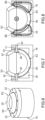
figure 1 est une vue en perspective d'un exemple d'interface haptique selon l'invention, - la
figure 2 est une vue en coupe de l'interface de lafigure 1 selon les plans AA et BB orthogonaux, - la
figure 3 est une vue extérieure de la liaison pivot intérieure représentée seule, - la
figure 4 est une vue en coupe longitudinale de l'interface de lafigure 1 selon le plan AA, dans laquelle la liaison pivot intérieure a été retirée - la
figure 5 est une vue en coupe longitudinale selon le plan BB orthogonal au plan AA dans laquelle la liaison pivot intérieure a été retirée, - la
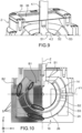
figure 6 est une vue extérieure de la liaison pivot extérieure représentée seule, - la
figure 7 est une vue en coupe longitudinale de l'interface de lafigure 1 selon le plan BB dans laquelle la liaison pivot extérieure a été retirée - la
figure 8 est une vue en coupe longitudinale selon le plan AA orthogonal au plan AA, dans laquelle la liaison pivot intérieure a été retirée, - la
figure 9 est une vue de détail de l'interface de lafigure 1 au niveau d'une membrane d'étanchéité, - la
figure 10 est une vue en coupe selon le plan de l'interface de lafigure 1 représentant les lignes de champ lorsque les bobines sont activées, - la
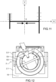
figure 11 est une représentation d'un exemple de combinaison de mouvements pouvant être imposée à l'effecteur grâce à la présente invention - la
figure 12 est une vue en coupe longitudinale selon la plan AA de l'interface de lafigure 1 dans une position extrême de l'effecteur. - la
figure 13A et lafigure 13B sont des vue en perspective d'un exemple d'interface comportant des capteurs permettant de détecter la position de l'effecteur. - Dans la description qui va suivre, les freins utilisent un fluide magnétorhéologique dont la viscosité est modifiée par application d'un champ magnétique. Néanmoins, la présente invention peut mettre en œuvre des freins à fluide électro-rhéologique, i.e. dont la viscosité est modifiée par application d'un champ électrique.
- Sur les
figures 1 et 2 , on peut voir un exemple d'une interface haptique selon l'invention. Il comporte un boîtier 2 et un effecteur 4 ou joystick destiné à être manipulé par un utilisateur. L'effecteur est monté dans le boîtier 2 mobile autour de deux axes X et Y, de préférence orthogonaux. Le joystick s'étend selon un axe Z orthogonal aux axes X et Y. - L'interface comporte deux articulations pivots P1 et P2 entre l'effecteur 4 et le boîtier 2, ces articulations intégrant chacune un frein à fluide magnétorhéologique. L'articulation pivot P1 et désignée « articulation pivot intérieure » et l'articulation pivot P2 est désignée « articulation pivot extérieure ».
- Sur les
figures 3, 4 et 5 , on peut voir l'articulation pivot intérieure P1 représentée seule. Elle comporte une première sphère S1 à laquelle est fixé l'effecteur 4, une deuxième sphère creuse S2 dans laquelle est logée la première sphère S1. La première sphère S1 et la deuxième sphère S2 sont concentriques. La deuxième sphère S2 comporte une ouverture 6 pour le passage de l'effecteur 4, l'ouverture 6 est dimensionnée pour offrir à l'effecteur un débattement suffisant. Un axe X1 s'étendant dans la direction X est prévu entre la première sphère S1 et la deuxième sphère S2, limitant ainsi le déplacement de la première sphère S1 par rapport à la deuxième sphère S2 à un déplacement en rotation autour de l'axe X. L'axe X1 traverse de part en part la première sphère et ses extrémités longitudinales sont reçues dans deux perçages 8 diamétralement opposés réalisés dans la paroi de la deuxième sphère. Avantageusement les extrémités de l'axe X1 sont reçues dans des paliers lisses 10 montés dans les perçages, réduisant ainsi les frottements. - Le diamètre extérieur de la première sphère S1 et le diamètre intérieur de la deuxième sphère S2 sont tels qu'un espace E1 suffisant pour recevoir du fluide magnétorhéologique est défini entre les deux sphères S1 et S2. La largeur de l'espace E1 est par exemple comprise entre 0,1 mm et 1 mm. Par exemple, ou une sphère S1 de rayon extérieur de 8 mm et une sphère S2 de rayon extérieur de 13 mm, l'espace E1 a une largeur de 0,25 mm.
- L'articulation pivot intérieure P1 comporte des moyens de génération d'un champ magnétique par exemple une bobine 14, logés dans la première sphère S1. De préférence la bobine 14 forme une partie de la surface extérieure de la première sphère S1 et est coaxiale avec l'effecteur. La disposition de la bobine par rapport à l'espace E1 est telle que les lignes de champ magnétique B1 générées par la bobine 14 traversent l'espace E1 et donc le fluide magnétorhéologique qu'il contient et modifie sa viscosité suivant l'amplitude du champ magnétique. La première sphère S1 et la deuxième sphère S2 forme un premier circuit magnétique.
- De manière très avantageuse, la bobine 14 est connectée à une alimentation électrique par une connexion filaire remontant par l'intérieur de la sphère S1 et par l'axe de l'effecteur 4 qui est avantageusement creux.
- La mise en œuvre du fluide magnétorhéologique et de la bobine permet d'intégrer un frein passif dans la première articulation pivot.
- L'articulation pivot extérieure P2 est représentée seule sur les
figures 6, 7 et 8 . L'articulation pivot extérieure P2 comporte une troisième sphère S3 creuse pour loger la deuxième sphère S2 et un logement 18 comportant un surface intérieure sphérique S4, logeant la troisième sphère S3, le logement 18 est fixe par rapport au boîtier. Dans l'exemple représenté, le logement S4 est formé par le boîtier 2 qui comporte une surface intérieure sphérique. La troisième sphère S3 et la surface intérieure S4 sont concentriques. - La troisième sphère comporte une ouverture 20 pour le passage de l'effecteur, celle-ci est dimensionnée pour permettre un débattement suffisant de l'effecteur, et le logement 18 comporte une ouverture 22 pour le passage de l'effecteur, celle-ci est dimensionnée pour permettre un débattement suffisant de l'effecteur,
- Un espace 2 est ménagé entre la surface extérieure de la troisième sphère S3 et la surface intérieure S4 pour loger du fluide magnétorhéologique.
- La liaison pivot extérieure P2 comporte des moyens de génération d'un champ magnétique par exemple une bobine électrique 24, logés dans le logement 18. De préférence, la bobine 24 forme une partie de la surface sphérique S4 et est coaxiale avec l'effecteur en position repos. La disposition de la bobine par rapport à l'espace E2 est telle que les lignes de champ magnétique B2 générées par la bobine 24 traversent l'espace E2 et donc le fluide magnétorhéologique qu'il contient et modifie sa viscosité suivant l'amplitude du champ magnétique. La troisième sphère S3 et le logement 18 forment un deuxième circuit magnétique.
- Dans l'exemple représenté, le boîtier 2 dans lequel est ménagé le logement 18 comporte une partie inférieure 2.1 en matériau ferromagnétique et une partie 2.2 en matériau amagnétique, ce qui permet de concentrer le flux magnétique sur des zones en regard avec la sphère S3, notamment lorsque celle-ci est dans une position extrême comme celle représenté sur la
figure 12 . Ainsi il n'y a pas de perte de flux magnétique hors de l'espace E1. - La mise en œuvre du fluide magnétorhéologique et de la bobine permet d'intégrer un frein passif dans l'articulation pivot extérieure P2.
- De préférence, la bobine 24 est portée par le logement 18, ainsi la connexion à la source électrique est simplifiée. En variante, la bobine 24 est portée par la troisième sphère S3.
- Deux axes Y1 s'étendant dans la direction Y sont prévus entre la troisième sphère S3 et le logement 18, limitant ainsi le déplacement de la troisième sphère S3 par rapport à au logement 18 à un déplacement en rotation autour de l'axe Y. Chaque axe Y1 est monté dans un perçage 28 réalisé dans la paroi de troisième sphère S3 et dans un perçage 30 réalisé dans le logement 18. Avantageusement et comme cela est représenté, les axes Y1 sont fixés dans les perçages 30 et sont montés dans des paliers lisses 32 logés dans les perçages 28.
- La deuxième sphère S2 est montée dans la troisième sphère S3.
- Les première, deuxième et troisième sphères et le logement 18 sont en matériau ferromagnétique, par exemple en fer doux.
- Une isolation magnétique est prévue entre les deux articulations pivots P1, P2 pour éviter que l'activation d'une bobine de l'une des liaisons pivots ait une action sur le fluide magnétorhéologique de l'autre liaison pivot. Ainsi les deux articulations P1 et P2 sont indépendantes et le ressenti haptique est largement amélioré. L'isolation magnétique est obtenue par une enveloppe amagnétique 26 formant entretoise entre la deuxième sphère S2 et la troisième sphère S3. Comme cela est visible sur la
figure 2 , l'enveloppe 26 est telle qu'elle enveloppe entièrement la deuxième sphère S2 et recouvre également les rebords de l'ouverture 6 afin de confiner au mieux les lignes de champ dans l'espace E1, et d'éviter que les lignes de champ B1 circulent dans la troisième sphère ou dans le fluide non compris dans l'espace E1. L'enveloppe 26 assure avantageusement l'immobilisation en rotation de la deuxième sphère S2 dans la troisième sphère S3. Dans l'exemple représenté, l'enveloppe 26 comporte des saillies radiales 34 pénétrant dans les perçages 28 de la troisième sphère S3 (figure 10 ), logeant les axes Y1. L'enveloppe 26 est par exemple en aluminium ou en matériau plastique non conducteur. - L'enveloppe est avantageusement moulée ou réalisée par impression 3D, notamment lorsqu'elle est en matériau plastique. En variante lorsqu'elle est en métal l'enveloppe peut être usinée.
- De manière très avantageuse et comme cela est représenté en détail sur la
figure 9 , le confinement étanche du fluide magnétorhéologique est réalisé au moyen d'une membrane 36 munie d'un passage pour le passage de l'effecteur et fixé sur l'effecteur et sur les bords de l'ouverture 22 du logement 18. Cette membrane présente l'avantage de ne pas générer de frottement contrairement à des joints toriques. - De manière avantageuse, la membrane 36 est tendue entre l'effecteur et le boîtier et possède des propriétés élastiques, elle assure alors une fonction de rappel de l'effecteur en position repos. Par exemple la membrane est réalisée dans un matériau élastomère compatible avec le fluide magnétorhéologique, notamment avec les huiles contenues dans les fluide magnétorhéologiques. Par exemple la membrane est copolymères butadiène-acrylonitrile, aussi appelés « caoutchoucs nitrile » désignés NBR (Nitrile Butadiene Rubber en terminologie anglo-saxonne) ou en EPDM (éthylène-propylène-diène monomère). L'intensité de la force de rappel peut être facilement ajustée en choisissant une membrane plus ou moins épaisse et/ou un matériau plus ou moins rigide.
- Dans l'exemple représenté, le bord extérieur de la membrane est pincé entre le boîtier et un couvercle 38, et l'effecteur comporte deux parties 4.1 et 4.2 par exemple solidarisées par vissage, le bord du passage est alors pincé entre les deux parties 4.1 et 4.2, un collage supplémentaire peut être envisagé. Le couvercle 38 est par exemple vissé sur le boîtier 2.
- Cet arrangement permet un remplissage facilité et simultané des deux espaces E1, E2 avec le fluide magnétorhéologique. Ensuite la membrane est mise en place. En variante, chaque espace est rempli avec un fluide différent et les deux espaces sont isolés de manière étanche l'un de l'autre.
- Il sera compris que pour l'assemblage de l'interface, plusieurs éléments sont réalisés en deux parties ou plus, tels que la deuxième sphère, la troisième sphère, le logement 18 est réalisée en deux parties. Les différentes parties de chaque sphère sont par exemple assemblées par collage.
- L'articulation ainsi réalisée bloque la rotation de l'effecteur autour de l'axe Z, ce qui est permet avantageusement à l'effecteur de conserver l'effecteur dans l'orientation définie.
- Sur la partie gauche de
figure 10 , la référence S désigne les zones de cisaillement du fluide, i.e. les zones des espaces E1 et E2 traversées par les lignes de champ B1 et B2 respectivement. On constate que lorsque les deux bobines génèrent chacune leur flux magnétique, il n'y pas de fuite de flux magnétique. Les deux freins sont donc isolés magnétiquement l'un de l'autre et peuvent être actionnés sans avoir d'effet sur l'autre frein. - Le fluide magnétorhéologique présent dans les espaces E1 et E2 est soumis à un phénomène de cisaillement lors de la rotation des sphères S1 et S3. La viscosité du fluide magnétorhéologique au repos étant faible, les couples exercés sur les sphères sont quasiment nuls. Cependant, lorsque la bobine d'un frein est parcourue par un courant électrique, un champ magnétique est généré dans son circuit magnétique. Le fluide est alors traversé en plusieurs zones par ce champ magnétique. Du fait de l'alignement des microparticules ferromagnétiques du fluide, sa viscosité est augmentée dans ces zones. Ce phénomène crée un effort résistant entre les sphères fixe et mobile, proportionnel à l'intensité du courant électrique de commande.
- Lorsque la bobine 14 est parcourue par un courant électrique de commande, un champ magnétique B1 est généré dans le circuit magnétique et traverse l'espace E1. Les microparticules ferromagnétiques du fluide magnétorhéologique s'alignent et sa viscosité augmente. Un couple proportionnel à l'intensité du courant électrique de commande s'oppose à la rotation de la première sphère S1 autour de l'axe X.
- Le fonctionnement est similaire lorsqu'un courant électrique traverse la bobine 24, un champ magnétique B2 est généré dans l'espace E2 et donc dans le fluide magnétorhéologique contenu dans l'espace E2, la viscosité apparente de celui augmente et un couple proportionnel à l'intensité du courant électrique de commande s'oppose à la rotation de la troisième sphère S3 autour de l'axe Y.
- Avantageusement, l'interface comporte des capteurs pour connaître les angles de rotation des sphères autour des directions X et Y. Par exemple, des capteurs de rotation peuvent être positionnés directement sur les axes X1 et Y1. De préférence et comme cela est représenté à titre d'exemple sur les
figures 13A et 13B , on mesure la rotation de l'effecteur autour des directions X et Y en utilisant par exemple des arceaux ARC1 et ARC2 montés respectivement en rotation autour des directions X et Y et comportant chacun une fenêtre F1 et F2 traversée par l'effecteur. Ainsi tout mouvement de l'effecteur autour des directions X et Y provoquent la rotation de l'arceau ARC1 autour de la direction X et/ou de l'arceau ARC2 autour de la direction Y. Des capteurs de rotations C1, et C2 sont par exemple positionnés au niveau des extrémités des arceaux articulées sur le boîtier. - Avantageusement, l'interface comporte également un capteur de détection de l'intention d'action de l'utilisateur sur l'effecteur, ce qui permet d'améliorer le comportement de l'interface, notamment en réduisant, voire en évitant les phénomènes de collage. Le capteur de détection de l'intention d'action de l'utilisateur comporte par exemple un capteur de couple autour de axes X ou Y et/ou un capteur de force autour des axes X et Y. Le capteur est par exemple disposé sous le boîtier, entre le boîtier et le bâti B sur lequel est fixée l'interface.
- Du fait de la différence de taille entre les deux circuits magnétiques, un effort de freinage moins important s'applique sur l'axe X. Les motifs haptiques sont conçus de sorte à tenir compte de cette différence de couple générale entre les deux freins.
- Dans l'exemple décrit, c'est le même fluide dans les deux espaces E1 et E2. Dans un autre exemple, chaque espace E1 et E2 est rempli avec un fluide différent, afin d'avoir une action en cisaillement serait plus forte sur l'axe X pour compenser la différence de taille entre les deux freins. Par exemple, le fluide remplissant l'espace E1 serait plus concentré en particules ferromagnétiques. Dans cet exemple des joints sont prévus entre les sphères pour éviter la circulation du fluide entre les deux espaces E1 et E2.
- La mise en œuvre de frein à fluide magnétorhéologique présente l'avantage d'être très robuste. En effet, si l'effort exercé par l'opérateur sur l'effecteur est trop important à l'encontre d'un couple de freinage, il n'y a aucune rupture de pièce du système, mais un glissement des sphères mobiles suite à une désolidarisation des chaînes de particules du fluide.
- Il peut être envisagé que la structure des deux articulations pivots soient mobiles le long de la direction Z, par exemple pour permettre un « clic », par exemple sur un bouton poussoir placé sous la structure.
- Sur la
figure 11 , on peut voir une visualisation d'un exemple d'un motif de déplacement réalisable grâce à la présente invention. - On souhaite que l'effecteur ne puisse se déplacer que suivant un motif haptique en forme de « H ». On considère un repère XOY avec l'origine O au centre de la barre du H, l'axe X contenant la barre du H. Les deux pieds du H sont orientés parallèlement à l'axe Y. Les deux freins peuvent être facilement configurés pour n'autoriser que ces déplacements.
- En outre, on souhaite une course suivante l'axe Y plus courte le long du pied situé à une valeur X<0 et pour des valeurs de Y>0 et Y<0, par rapport au pied situé à valeur de X>0.
- En outre, on souhaite un crantage serré (symbolisé par les traits rapprochés) sur la course le long de Y pour X<0 et Y>0, haut », et un crantage distant (symbolisé par traits plus éloignés) sur la course le long de Y pour X>0 et Y>0.
- La limitation du déplacement selon X et/ou Y est obtenu en activant le ou les freins de sorte que le couple ou les couples de freinage générés soient suffisants pour bloquer le déplacement de l'effecteur à la fois autour de l'axe X et autour de l'axe Y.
- Le dispositif selon l'invention présente une grande compacité. Par exemple le boîtier 2 peut présenter un diamètre extérieur de 34 mm et une hauteur de 30 mm. Il peut ainsi être relativement facilement intégrable dans des commandes mobiles, type tablette ou manette.
- La présente invention s'applique à des interfaces de commande de type joystick qui nécessitent une configuration suivant l'usage, par exemple à des joysticks pour la commande de machines de type pont roulant, machines de manutention, et à des manettes de jeux vidéo, dans les télécommandes pour le modélisme.
Claims (10)
- Structure pour interface haptique à deux degrés de liberté comportant :- un élément d'interaction avec l'utilisateur, destiné à être mobile selon deux degrés de liberté,- un premier frein passif et un deuxième frein passif aptes à exercer un effort résistant autour d'un premier axe et d'un deuxième axe respectivement,- le premier frein passif comportant une première liaison pivot (P1) autour d'une première direction de rotation (X) comportant un premier élément sphérique (S1) auquel est fixé l'effecteur (4), reçu dans un deuxième élément sphérique (S2) formant logement pour le premier élément sphérique (S1), le déplacement du premier élément sphérique (S1) dans le deuxième élément sphérique (S2) étant une rotation autour de la première direction de rotation (X),- le deuxième frein passif comportant une deuxième liaison pivot autour d'une deuxième direction de rotation (Y) comportant un troisième élément sphérique (S3) solidaire en mouvement du deuxième élément sphérique (S2) et reçu dans un logement (18) comportant une paroi sphérique (S4), le déplacement du troisième élément sphérique (S3) dans le logement (18) étant une rotation autour de la deuxième direction de rotation (Y),- un premier fluide dont la viscosité apparente varie en fonction d'un premier stimulus extérieur entre le premier élément sphérique (S1) et le deuxième élément sphérique (S2),- un deuxième fluide dont la viscosité apparente varie en fonction d'un deuxième stimulus extérieur entre le troisième élément sphérique (S3) et le logement (18),- des moyens de génération desdits premier et deuxième stimuli sur commande dans lesdits premier et deuxième fluides.
- Structure selon la revendication 1, dans laquelle le premier et le deuxième fluide sont des fluides magnétorhéologiques, dans lequel les moyens de génération des premier et deuxième stimulus comportent un première bobine électrique (14) portée par le premier élément sphérique (S1) ou le deuxième élément (S2) et une deuxième bobine électrique (24) portée par le troisième élément (S3) ou le logement (18), et dans lequel au moins une partie du premier élément sphérique (S1) et une partie du deuxième élément sphérique (S2) forment un premier circuit magnétique et au moins une partie du troisième élément sphérique (S3) et une partie du logement (18) forment un deuxième circuit magnétique.
- Structure selon la revendication 2, comporte une enveloppe (26) en matériau amagnétique entre le deuxième élément sphérique (S2) et le troisième élément sphérique(S3) isolant le premier circuit magnétique dans le premier frein et le deuxième circuit magnétique dans le deuxième frein.
- Structure selon l'une des revendications 1 à 3, comportant un premier axe (X1) traversant le premier élément sphérique (S1) et dont les extrémités sont reçues dans le deuxième élément sphérique (S2), ledit premier axe (X1) étant coaxial avec la première direction de rotation (X), et des deuxièmes axes (Y1) alignés montés chacun entre le troisième élément sphérique (S3) et le logement (18), les deux deuxièmes axes (Y1) étant coaxiaux à la deuxième direction de rotation (Y).
- Structure selon la revendication 2 ou la revendication 3 en combinaison avec la revendication 4, dans laquelle la première bobine (14) est dans le premier élément sphérique (S1) et une connexion électrique de ladite bobine (14) avec une source électrique passe à travers le premier axe (X1).
- Structure selon l'une des revendications 1 à 5, comportant un boîtier (2) logeant les premier et deuxième freins passifs et comprenant une ouverture duquel fait saillie l'effecteur (4), ladite interface comportant également une membrane (36) fixée de manière étanche au bord de l'ouverture du boîtier et à l'effecteur de sorte à confiner les premier et deuxième fluides dans le boîtier.
- Structure selon la revendication précédente, dans laquelle le premier et le deuxième fluide sont les mêmes et dans lequel le remplissage en fluide de la structure se fait par ladite ouverture du boîtier.
- Structure selon la revendication 6 ou la revendication 7, dans laquelle la membrane (36) présente des propriétés élastiques telles qu'elles assurent une fonction de rappel sur l'effecteur.
- Interface haptique comportant :- une structure selon l'une des revendications précédentes,- des moyens de mesure d'une position de l'élément d'interaction avec un utilisateur,- une unité de commande apte à envoyer des ordres audits freins en fonction des informations sur la position de l'élément d'interaction avec l'utilisateur, de sorte que lesdits freins passifs génèrent des efforts résistants selon au moins un motif haptique donné.
- Interface de commande portable pour machine comportant au moins une interface haptique selon la revendication précédente.
Applications Claiming Priority (2)
| Application Number | Priority Date | Filing Date | Title |
|---|---|---|---|
| FR2013864A FR3118215B1 (fr) | 2020-12-21 | 2020-12-21 | Structure pour interface haptique a deux degrés de liberté |
| PCT/FR2021/052308 WO2022136768A1 (fr) | 2020-12-21 | 2021-12-13 | Structure pour interface haptique a deux degrés de liberté |
Publications (2)
| Publication Number | Publication Date |
|---|---|
| EP4264397A1 EP4264397A1 (fr) | 2023-10-25 |
| EP4264397B1 true EP4264397B1 (fr) | 2025-02-05 |
Family
ID=74759056
Family Applications (1)
| Application Number | Title | Priority Date | Filing Date |
|---|---|---|---|
| EP21851671.4A Active EP4264397B1 (fr) | 2020-12-21 | 2021-12-13 | Structure pour interface haptique a deux degrés de liberté |
Country Status (3)
| Country | Link |
|---|---|
| EP (1) | EP4264397B1 (fr) |
| FR (1) | FR3118215B1 (fr) |
| WO (1) | WO2022136768A1 (fr) |
Families Citing this family (1)
| Publication number | Priority date | Publication date | Assignee | Title |
|---|---|---|---|---|
| DE102023125682A1 (de) * | 2023-09-21 | 2025-03-27 | Karl Storz Se & Co. Kg | Haptische vorrichtung |
Family Cites Families (2)
| Publication number | Priority date | Publication date | Assignee | Title |
|---|---|---|---|---|
| FR2887657B1 (fr) * | 2005-06-27 | 2007-09-07 | Itt Mfg Enterprises Inc | Dispositif a boule de commande des deplacements d'un curseur sur un ecran |
| FR3056315B1 (fr) | 2016-09-21 | 2018-09-28 | Commissariat A L'energie Atomique Et Aux Energies Alternatives | Interface haptique a au moins deux degres de liberte presentant un ressenti haptique ameliore |
-
2020
- 2020-12-21 FR FR2013864A patent/FR3118215B1/fr active Active
-
2021
- 2021-12-13 EP EP21851671.4A patent/EP4264397B1/fr active Active
- 2021-12-13 WO PCT/FR2021/052308 patent/WO2022136768A1/fr not_active Ceased
Also Published As
| Publication number | Publication date |
|---|---|
| FR3118215B1 (fr) | 2022-12-09 |
| EP4264397A1 (fr) | 2023-10-25 |
| FR3118215A1 (fr) | 2022-06-24 |
| WO2022136768A1 (fr) | 2022-06-30 |
Similar Documents
| Publication | Publication Date | Title |
|---|---|---|
| EP3516483B1 (fr) | Interface haptique a au moins deux degres de liberte presentant un ressenti haptique ameliore | |
| EP2277095B1 (fr) | Actionneur electromagnetique et dispositif de commande a retour haptique correspondant | |
| EP4154090A1 (fr) | Interface de commande à retour haptique | |
| FR3010547A1 (fr) | Interface de commande a retour haptique | |
| WO2009133056A1 (fr) | Interface a retour d'effort a sensation ameliorée | |
| FR2831626A1 (fr) | Joint homocinetique fixe notamment destine a une colonne de direction de vehicule automobile | |
| EP4264397B1 (fr) | Structure pour interface haptique a deux degrés de liberté | |
| EP3198369B1 (fr) | Procédé et interface de commande à retour haptique pour véhicule automobile | |
| WO2015150439A2 (fr) | Dispositif de commande passif magnétique | |
| EP2244168B1 (fr) | Dispositif de commande à retour haptique et actionneur correspondant | |
| EP3198368A1 (fr) | Procédé et interface de commande à retour haptique pour véhicule automobile | |
| FR3010550B1 (fr) | Procede et interface de commande a retour haptique pour vehicule automobile | |
| WO2005010743A9 (fr) | Peripherique d'entree pour ordinateur ou similaire | |
| FR3084940A1 (fr) | Interface de commande a retour haptique | |
| FR3026501A1 (fr) | Procede et interface de commande a retour haptique pour vehicule automobile | |
| EP3215911A1 (fr) | Procédé et interface de commande à retour haptique pour véhicule automobile | |
| JP2008076161A (ja) | 荷重センサ | |
| EP3198371B1 (fr) | Interface de commande à retour haptique pour véhicule automobile | |
| FR2900086A1 (fr) | Organe de commande a cables tendus | |
| FR2859783A1 (fr) | Organe de manoeuvre | |
| FR2861473A1 (fr) | Dispositif de pointage bi-dimensionnel | |
| WO2016016520A1 (fr) | Interface et procede de commande d'une interface de commande a retour haptique pour vehicule automobile |
Legal Events
| Date | Code | Title | Description |
|---|---|---|---|
| STAA | Information on the status of an ep patent application or granted ep patent |
Free format text: STATUS: UNKNOWN |
|
| STAA | Information on the status of an ep patent application or granted ep patent |
Free format text: STATUS: THE INTERNATIONAL PUBLICATION HAS BEEN MADE |
|
| PUAI | Public reference made under article 153(3) epc to a published international application that has entered the european phase |
Free format text: ORIGINAL CODE: 0009012 |
|
| STAA | Information on the status of an ep patent application or granted ep patent |
Free format text: STATUS: REQUEST FOR EXAMINATION WAS MADE |
|
| 17P | Request for examination filed |
Effective date: 20230621 |
|
| AK | Designated contracting states |
Kind code of ref document: A1 Designated state(s): AL AT BE BG CH CY CZ DE DK EE ES FI FR GB GR HR HU IE IS IT LI LT LU LV MC MK MT NL NO PL PT RO RS SE SI SK SM TR |
|
| DAV | Request for validation of the european patent (deleted) | ||
| DAX | Request for extension of the european patent (deleted) | ||
| GRAP | Despatch of communication of intention to grant a patent |
Free format text: ORIGINAL CODE: EPIDOSNIGR1 |
|
| STAA | Information on the status of an ep patent application or granted ep patent |
Free format text: STATUS: GRANT OF PATENT IS INTENDED |
|
| INTG | Intention to grant announced |
Effective date: 20240902 |
|
| RAP3 | Party data changed (applicant data changed or rights of an application transferred) |
Owner name: COMMISSARIAT A L'ENERGIE ATOMIQUE ET AUX ENERGIESALTERNATIVES |
|
| GRAS | Grant fee paid |
Free format text: ORIGINAL CODE: EPIDOSNIGR3 |
|
| GRAA | (expected) grant |
Free format text: ORIGINAL CODE: 0009210 |
|
| STAA | Information on the status of an ep patent application or granted ep patent |
Free format text: STATUS: THE PATENT HAS BEEN GRANTED |
|
| AK | Designated contracting states |
Kind code of ref document: B1 Designated state(s): AL AT BE BG CH CY CZ DE DK EE ES FI FR GB GR HR HU IE IS IT LI LT LU LV MC MK MT NL NO PL PT RO RS SE SI SK SM TR |
|
| REG | Reference to a national code |
Ref country code: GB Ref legal event code: FG4D Free format text: NOT ENGLISH |
|
| REG | Reference to a national code |
Ref country code: CH Ref legal event code: EP |
|
| REG | Reference to a national code |
Ref country code: IE Ref legal event code: FG4D Free format text: LANGUAGE OF EP DOCUMENT: FRENCH |
|
| REG | Reference to a national code |
Ref country code: DE Ref legal event code: R096 Ref document number: 602021025832 Country of ref document: DE |
|
| REG | Reference to a national code |
Ref country code: NL Ref legal event code: MP Effective date: 20250205 |
|
| PG25 | Lapsed in a contracting state [announced via postgrant information from national office to epo] |
Ref country code: RS Free format text: LAPSE BECAUSE OF FAILURE TO SUBMIT A TRANSLATION OF THE DESCRIPTION OR TO PAY THE FEE WITHIN THE PRESCRIBED TIME-LIMIT Effective date: 20250505 |
|
| PG25 | Lapsed in a contracting state [announced via postgrant information from national office to epo] |
Ref country code: FI Free format text: LAPSE BECAUSE OF FAILURE TO SUBMIT A TRANSLATION OF THE DESCRIPTION OR TO PAY THE FEE WITHIN THE PRESCRIBED TIME-LIMIT Effective date: 20250205 |
|
| PG25 | Lapsed in a contracting state [announced via postgrant information from national office to epo] |
Ref country code: PL Free format text: LAPSE BECAUSE OF FAILURE TO SUBMIT A TRANSLATION OF THE DESCRIPTION OR TO PAY THE FEE WITHIN THE PRESCRIBED TIME-LIMIT Effective date: 20250205 |
|
| PG25 | Lapsed in a contracting state [announced via postgrant information from national office to epo] |
Ref country code: ES Free format text: LAPSE BECAUSE OF FAILURE TO SUBMIT A TRANSLATION OF THE DESCRIPTION OR TO PAY THE FEE WITHIN THE PRESCRIBED TIME-LIMIT Effective date: 20250205 |
|
| REG | Reference to a national code |
Ref country code: LT Ref legal event code: MG9D |
|
| PG25 | Lapsed in a contracting state [announced via postgrant information from national office to epo] |
Ref country code: IS Free format text: LAPSE BECAUSE OF FAILURE TO SUBMIT A TRANSLATION OF THE DESCRIPTION OR TO PAY THE FEE WITHIN THE PRESCRIBED TIME-LIMIT Effective date: 20250605 Ref country code: NO Free format text: LAPSE BECAUSE OF FAILURE TO SUBMIT A TRANSLATION OF THE DESCRIPTION OR TO PAY THE FEE WITHIN THE PRESCRIBED TIME-LIMIT Effective date: 20250505 |
|
| PG25 | Lapsed in a contracting state [announced via postgrant information from national office to epo] |
Ref country code: NL Free format text: LAPSE BECAUSE OF FAILURE TO SUBMIT A TRANSLATION OF THE DESCRIPTION OR TO PAY THE FEE WITHIN THE PRESCRIBED TIME-LIMIT Effective date: 20250205 |
|
| PG25 | Lapsed in a contracting state [announced via postgrant information from national office to epo] |
Ref country code: HR Free format text: LAPSE BECAUSE OF FAILURE TO SUBMIT A TRANSLATION OF THE DESCRIPTION OR TO PAY THE FEE WITHIN THE PRESCRIBED TIME-LIMIT Effective date: 20250205 |
|
| PG25 | Lapsed in a contracting state [announced via postgrant information from national office to epo] |
Ref country code: LV Free format text: LAPSE BECAUSE OF FAILURE TO SUBMIT A TRANSLATION OF THE DESCRIPTION OR TO PAY THE FEE WITHIN THE PRESCRIBED TIME-LIMIT Effective date: 20250205 Ref country code: PT Free format text: LAPSE BECAUSE OF FAILURE TO SUBMIT A TRANSLATION OF THE DESCRIPTION OR TO PAY THE FEE WITHIN THE PRESCRIBED TIME-LIMIT Effective date: 20250605 |
|
| PG25 | Lapsed in a contracting state [announced via postgrant information from national office to epo] |
Ref country code: BG Free format text: LAPSE BECAUSE OF FAILURE TO SUBMIT A TRANSLATION OF THE DESCRIPTION OR TO PAY THE FEE WITHIN THE PRESCRIBED TIME-LIMIT Effective date: 20250205 Ref country code: GR Free format text: LAPSE BECAUSE OF FAILURE TO SUBMIT A TRANSLATION OF THE DESCRIPTION OR TO PAY THE FEE WITHIN THE PRESCRIBED TIME-LIMIT Effective date: 20250506 |
|
| REG | Reference to a national code |
Ref country code: AT Ref legal event code: MK05 Ref document number: 1764991 Country of ref document: AT Kind code of ref document: T Effective date: 20250205 |
|
| PG25 | Lapsed in a contracting state [announced via postgrant information from national office to epo] |
Ref country code: SE Free format text: LAPSE BECAUSE OF FAILURE TO SUBMIT A TRANSLATION OF THE DESCRIPTION OR TO PAY THE FEE WITHIN THE PRESCRIBED TIME-LIMIT Effective date: 20250205 |
|
| PG25 | Lapsed in a contracting state [announced via postgrant information from national office to epo] |
Ref country code: SM Free format text: LAPSE BECAUSE OF FAILURE TO SUBMIT A TRANSLATION OF THE DESCRIPTION OR TO PAY THE FEE WITHIN THE PRESCRIBED TIME-LIMIT Effective date: 20250205 |
|
| PG25 | Lapsed in a contracting state [announced via postgrant information from national office to epo] |
Ref country code: DK Free format text: LAPSE BECAUSE OF FAILURE TO SUBMIT A TRANSLATION OF THE DESCRIPTION OR TO PAY THE FEE WITHIN THE PRESCRIBED TIME-LIMIT Effective date: 20250205 |
|
| PG25 | Lapsed in a contracting state [announced via postgrant information from national office to epo] |
Ref country code: IT Free format text: LAPSE BECAUSE OF FAILURE TO SUBMIT A TRANSLATION OF THE DESCRIPTION OR TO PAY THE FEE WITHIN THE PRESCRIBED TIME-LIMIT Effective date: 20250205 |
|
| PG25 | Lapsed in a contracting state [announced via postgrant information from national office to epo] |
Ref country code: AT Free format text: LAPSE BECAUSE OF FAILURE TO SUBMIT A TRANSLATION OF THE DESCRIPTION OR TO PAY THE FEE WITHIN THE PRESCRIBED TIME-LIMIT Effective date: 20250205 |
|
| PG25 | Lapsed in a contracting state [announced via postgrant information from national office to epo] |
Ref country code: EE Free format text: LAPSE BECAUSE OF FAILURE TO SUBMIT A TRANSLATION OF THE DESCRIPTION OR TO PAY THE FEE WITHIN THE PRESCRIBED TIME-LIMIT Effective date: 20250205 Ref country code: CZ Free format text: LAPSE BECAUSE OF FAILURE TO SUBMIT A TRANSLATION OF THE DESCRIPTION OR TO PAY THE FEE WITHIN THE PRESCRIBED TIME-LIMIT Effective date: 20250205 |
|
| PG25 | Lapsed in a contracting state [announced via postgrant information from national office to epo] |
Ref country code: RO Free format text: LAPSE BECAUSE OF FAILURE TO SUBMIT A TRANSLATION OF THE DESCRIPTION OR TO PAY THE FEE WITHIN THE PRESCRIBED TIME-LIMIT Effective date: 20250205 |
|
| PG25 | Lapsed in a contracting state [announced via postgrant information from national office to epo] |
Ref country code: SK Free format text: LAPSE BECAUSE OF FAILURE TO SUBMIT A TRANSLATION OF THE DESCRIPTION OR TO PAY THE FEE WITHIN THE PRESCRIBED TIME-LIMIT Effective date: 20250205 |
|
| REG | Reference to a national code |
Ref country code: DE Ref legal event code: R097 Ref document number: 602021025832 Country of ref document: DE |
|
| PLBE | No opposition filed within time limit |
Free format text: ORIGINAL CODE: 0009261 |
|
| STAA | Information on the status of an ep patent application or granted ep patent |
Free format text: STATUS: NO OPPOSITION FILED WITHIN TIME LIMIT |
|
| 26N | No opposition filed |
Effective date: 20251106 |