EP4264397B1 - Struktur für eine haptische schnittstelle mit zwei freiheitsgraden - Google Patents
Struktur für eine haptische schnittstelle mit zwei freiheitsgraden Download PDFInfo
- Publication number
- EP4264397B1 EP4264397B1 EP21851671.4A EP21851671A EP4264397B1 EP 4264397 B1 EP4264397 B1 EP 4264397B1 EP 21851671 A EP21851671 A EP 21851671A EP 4264397 B1 EP4264397 B1 EP 4264397B1
- Authority
- EP
- European Patent Office
- Prior art keywords
- spherical element
- housing
- rotation
- effector
- spherical
- Prior art date
- Legal status (The legal status is an assumption and is not a legal conclusion. Google has not performed a legal analysis and makes no representation as to the accuracy of the status listed.)
- Active
Links
Images


Classifications
-
- G—PHYSICS
- G05—CONTROLLING; REGULATING
- G05G—CONTROL DEVICES OR SYSTEMS INSOFAR AS CHARACTERISED BY MECHANICAL FEATURES ONLY
- G05G5/00—Means for preventing, limiting or returning the movements of parts of a control mechanism, e.g. locking controlling member
- G05G5/03—Means for enhancing the operator's awareness of arrival of the controlling member at a command or datum position; Providing feel, e.g. means for creating a counterforce
-
- G—PHYSICS
- G05—CONTROLLING; REGULATING
- G05G—CONTROL DEVICES OR SYSTEMS INSOFAR AS CHARACTERISED BY MECHANICAL FEATURES ONLY
- G05G9/00—Manually-actuated control mechanisms provided with one single controlling member co-operating with two or more controlled members, e.g. selectively, simultaneously
- G05G9/02—Manually-actuated control mechanisms provided with one single controlling member co-operating with two or more controlled members, e.g. selectively, simultaneously the controlling member being movable in different independent ways, movement in each individual way actuating one controlled member only
- G05G9/04—Manually-actuated control mechanisms provided with one single controlling member co-operating with two or more controlled members, e.g. selectively, simultaneously the controlling member being movable in different independent ways, movement in each individual way actuating one controlled member only in which movement in two or more ways can occur simultaneously
- G05G9/047—Manually-actuated control mechanisms provided with one single controlling member co-operating with two or more controlled members, e.g. selectively, simultaneously the controlling member being movable in different independent ways, movement in each individual way actuating one controlled member only in which movement in two or more ways can occur simultaneously the controlling member being movable by hand about orthogonal axes, e.g. joysticks
-
- G—PHYSICS
- G06—COMPUTING OR CALCULATING; COUNTING
- G06F—ELECTRIC DIGITAL DATA PROCESSING
- G06F3/00—Input arrangements for transferring data to be processed into a form capable of being handled by the computer; Output arrangements for transferring data from processing unit to output unit, e.g. interface arrangements
- G06F3/01—Input arrangements or combined input and output arrangements for interaction between user and computer
- G06F3/016—Input arrangements with force or tactile feedback as computer generated output to the user
-
- G—PHYSICS
- G06—COMPUTING OR CALCULATING; COUNTING
- G06F—ELECTRIC DIGITAL DATA PROCESSING
- G06F3/00—Input arrangements for transferring data to be processed into a form capable of being handled by the computer; Output arrangements for transferring data from processing unit to output unit, e.g. interface arrangements
- G06F3/01—Input arrangements or combined input and output arrangements for interaction between user and computer
- G06F3/03—Arrangements for converting the position or the displacement of a member into a coded form
- G06F3/033—Pointing devices displaced or positioned by the user, e.g. mice, trackballs, pens or joysticks; Accessories therefor
- G06F3/0338—Pointing devices displaced or positioned by the user, e.g. mice, trackballs, pens or joysticks; Accessories therefor with detection of limited linear or angular displacement of an operating part of the device from a neutral position, e.g. isotonic or isometric joysticks
-
- G—PHYSICS
- G06—COMPUTING OR CALCULATING; COUNTING
- G06F—ELECTRIC DIGITAL DATA PROCESSING
- G06F3/00—Input arrangements for transferring data to be processed into a form capable of being handled by the computer; Output arrangements for transferring data from processing unit to output unit, e.g. interface arrangements
- G06F3/01—Input arrangements or combined input and output arrangements for interaction between user and computer
- G06F3/03—Arrangements for converting the position or the displacement of a member into a coded form
- G06F3/033—Pointing devices displaced or positioned by the user, e.g. mice, trackballs, pens or joysticks; Accessories therefor
- G06F3/038—Control and interface arrangements therefor, e.g. drivers or device-embedded control circuitry
- G06F3/0383—Signal control means within the pointing device
-
- G—PHYSICS
- G05—CONTROLLING; REGULATING
- G05G—CONTROL DEVICES OR SYSTEMS INSOFAR AS CHARACTERISED BY MECHANICAL FEATURES ONLY
- G05G9/00—Manually-actuated control mechanisms provided with one single controlling member co-operating with two or more controlled members, e.g. selectively, simultaneously
- G05G9/02—Manually-actuated control mechanisms provided with one single controlling member co-operating with two or more controlled members, e.g. selectively, simultaneously the controlling member being movable in different independent ways, movement in each individual way actuating one controlled member only
- G05G9/04—Manually-actuated control mechanisms provided with one single controlling member co-operating with two or more controlled members, e.g. selectively, simultaneously the controlling member being movable in different independent ways, movement in each individual way actuating one controlled member only in which movement in two or more ways can occur simultaneously
- G05G9/047—Manually-actuated control mechanisms provided with one single controlling member co-operating with two or more controlled members, e.g. selectively, simultaneously the controlling member being movable in different independent ways, movement in each individual way actuating one controlled member only in which movement in two or more ways can occur simultaneously the controlling member being movable by hand about orthogonal axes, e.g. joysticks
- G05G2009/04703—Mounting of controlling member
- G05G2009/04707—Mounting of controlling member with ball joint
-
- G—PHYSICS
- G05—CONTROLLING; REGULATING
- G05G—CONTROL DEVICES OR SYSTEMS INSOFAR AS CHARACTERISED BY MECHANICAL FEATURES ONLY
- G05G9/00—Manually-actuated control mechanisms provided with one single controlling member co-operating with two or more controlled members, e.g. selectively, simultaneously
- G05G9/02—Manually-actuated control mechanisms provided with one single controlling member co-operating with two or more controlled members, e.g. selectively, simultaneously the controlling member being movable in different independent ways, movement in each individual way actuating one controlled member only
- G05G9/04—Manually-actuated control mechanisms provided with one single controlling member co-operating with two or more controlled members, e.g. selectively, simultaneously the controlling member being movable in different independent ways, movement in each individual way actuating one controlled member only in which movement in two or more ways can occur simultaneously
- G05G9/047—Manually-actuated control mechanisms provided with one single controlling member co-operating with two or more controlled members, e.g. selectively, simultaneously the controlling member being movable in different independent ways, movement in each individual way actuating one controlled member only in which movement in two or more ways can occur simultaneously the controlling member being movable by hand about orthogonal axes, e.g. joysticks
- G05G2009/04703—Mounting of controlling member
- G05G2009/04714—Mounting of controlling member with orthogonal axes
-
- G—PHYSICS
- G05—CONTROLLING; REGULATING
- G05G—CONTROL DEVICES OR SYSTEMS INSOFAR AS CHARACTERISED BY MECHANICAL FEATURES ONLY
- G05G9/00—Manually-actuated control mechanisms provided with one single controlling member co-operating with two or more controlled members, e.g. selectively, simultaneously
- G05G9/02—Manually-actuated control mechanisms provided with one single controlling member co-operating with two or more controlled members, e.g. selectively, simultaneously the controlling member being movable in different independent ways, movement in each individual way actuating one controlled member only
- G05G9/04—Manually-actuated control mechanisms provided with one single controlling member co-operating with two or more controlled members, e.g. selectively, simultaneously the controlling member being movable in different independent ways, movement in each individual way actuating one controlled member only in which movement in two or more ways can occur simultaneously
- G05G9/047—Manually-actuated control mechanisms provided with one single controlling member co-operating with two or more controlled members, e.g. selectively, simultaneously the controlling member being movable in different independent ways, movement in each individual way actuating one controlled member only in which movement in two or more ways can occur simultaneously the controlling member being movable by hand about orthogonal axes, e.g. joysticks
- G05G2009/04766—Manually-actuated control mechanisms provided with one single controlling member co-operating with two or more controlled members, e.g. selectively, simultaneously the controlling member being movable in different independent ways, movement in each individual way actuating one controlled member only in which movement in two or more ways can occur simultaneously the controlling member being movable by hand about orthogonal axes, e.g. joysticks providing feel, e.g. indexing means, means to create counterforce
-
- G—PHYSICS
- G06—COMPUTING OR CALCULATING; COUNTING
- G06F—ELECTRIC DIGITAL DATA PROCESSING
- G06F2203/00—Indexing scheme relating to G06F3/00 - G06F3/048
- G06F2203/01—Indexing scheme relating to G06F3/01
- G06F2203/015—Force feedback applied to a joystick
Definitions
- the present invention relates to a structure for a two-degree-of-freedom haptic interface with reduced bulk, and to a haptic interface comprising such a structure.
- a haptic interface can be used to command or control a system, such as a handling machine or an overhead crane or in the entertainment field for video game controllers or remote controls in model making.
- the haptic interface comprises an effector, also called a joystick, with two degrees of freedom.
- a resistive force opposes the movement of the effector depending on its position, for example.
- By modulating the resistive force depending on the position of the effector and the desired direction it is possible to guide the movement of the joystick in preferred directions and to define haptic patterns, such as a notch, which will be felt by the user when moving the effector.
- the document EP3516483 describes a haptic interface comprising a joystick with at least two degrees of freedom implementing two magnetorheological brakes which form two passive brakes, each braking more or less the rotation of an axis which is connected by a cardan system to the joystick. Passive brakes can only generate a resistive force opposing a force applied by the user. This interface is satisfactory, however it has a significant bulkiness which does not allow its integration into portable or mobile systems.
- a structure for a haptic interface with two degrees of freedom in rotation comprising an effector intended to be manipulated by the user and two pivot joints around two axes, to which the effector is connected, the two pivot joints being nested one inside the other and forming passive brakes around each of their axes.
- Each brake uses, for example, a magnetorheological fluid.
- This brake system allows the movements of the effector to be controlled independently in both directions. In addition, by nesting the two pivot joints, a significant space saving is obtained.
- each pivot joint is formed by a ball joint limited to rotation about a single axis. One of the joints is received in the other joint.
- Each pivot connection has an inner sphere received in an outer sphere, the magnetorheological fluid being received between the two spheres.
- the magnetorheological fluid is confined in the interface housing by means of a membrane.
- this membrane reduces friction and makes the movement of the effector more transparent, particularly during operation without the application of braking.
- it can provide a function of returning the effector to the rest position.
- the first and second fluids are magnetorheological fluids.
- the means for generating the first and second stimuli comprise a first electric coil carried by the first spherical element or the second element and a second electric coil carried by the third element or the housing. At least a portion of the first spherical element and a portion of the second spherical element form a first magnetic circuit and at least a portion of the third spherical element and a portion of the housing form a second magnetic circuit.
- the structure may comprise an envelope of non-magnetic material between the second spherical element and the third spherical element isolating the first magnetic circuit in the first brake and the second magnetic circuit in the second brake.
- the structure comprises a first axis passing through the first spherical element and the ends of which are received in the second spherical element, said first axis being coaxial with the first direction of rotation, and second aligned axes each mounted between the third spherical element and the housing, the two second axes being coaxial with the second direction of rotation.
- the first coil is in the first spherical element and an electrical connection of said coil with an electrical source passes through the first axis.
- the structure according to may comprise a housing housing the first and second haptic brakes and comprising an opening from which the effector projects, said interface also comprising a membrane sealed to the edge of the opening of the housing and to the effector so as to confine the first and second fluids in the housing.
- the first and second fluids are the same and the fluid filling of the structure is done through said opening of the housing.
- the membrane has elastic properties such that they provide a return function on the effector.
- the present application also relates to a portable control interface for a machine comprising at least one haptic interface according to the invention.
- the brakes use a magnetorheological fluid whose viscosity is modified by application of a magnetic field.
- the present invention can implement brakes with electro-rheological fluid, i.e. whose viscosity is modified by application of an electric field.
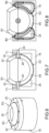
- a haptic interface according to the invention. It comprises a housing 2 and an effector 4 or joystick intended to be manipulated by a user.
- the effector is mounted in the housing 2 movable around two axes X and Y, preferably orthogonal.
- the joystick extends along an axis Z orthogonal to the axes X and Y.
- the interface comprises two pivot joints P1 and P2 between the effector 4 and the housing 2, these joints each integrating a magnetorheological fluid brake.
- the pivot joint P1 is designated “inner pivot joint” and the pivot joint P2 is designated “outer pivot joint”.
- the inner pivot joint P1 shown alone. It comprises a first sphere S1 to which the effector 4 is fixed, a second hollow sphere S2 in which the first sphere S1 is housed.
- the first sphere S1 and the second sphere S2 are concentric.
- the second sphere S2 comprises an opening 6 for the passage of the effector 4, the opening 6 is sized to offer the effector sufficient clearance.
- An axis X1 extending in the X direction is provided between the first sphere S1 and the second sphere S2, thus limiting the movement of the first sphere S1 relative to the second sphere S2 to a rotational movement about the X axis.
- the axis X1 passes right through the first sphere and its longitudinal ends are received in two diametrically opposed holes 8 made in the wall of the second sphere.
- the ends of the X1 axis are received in plain bearings 10 mounted in the holes, thus reducing friction.
- the outer diameter of the first sphere S1 and the inner diameter of the second sphere S2 are such that a space E1 sufficient to receive fluid magnetorheological space is defined between the two spheres S1 and S2.
- the width of the space E1 is for example between 0.1 mm and 1 mm.
- the space E1 has a width of 0.25 mm.
- the inner pivot joint P1 comprises means for generating a magnetic field, for example a coil 14, housed in the first sphere S1.
- the coil 14 forms a part of the outer surface of the first sphere S1 and is coaxial with the effector.
- the arrangement of the coil relative to the space E1 is such that the magnetic field lines B1 generated by the coil 14 pass through the space E1 and therefore the magnetorheological fluid that it contains and modify its viscosity according to the amplitude of the magnetic field.
- the first sphere S1 and the second sphere S2 form a first magnetic circuit.
- the coil 14 is connected to a power supply by a wired connection going up through the inside of the sphere S1 and through the axis of the effector 4 which is advantageously hollow.
- the implementation of the magnetorheological fluid and the coil allows the integration of a passive brake in the first pivot joint.
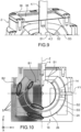
- the external pivot joint P2 is shown alone on the Figures 6, 7 and 8 .
- the outer pivot joint P2 comprises a third hollow sphere S3 for housing the second sphere S2 and a housing 18 comprising a spherical inner surface S4, housing the third sphere S3, the housing 18 is fixed relative to the housing.
- the housing S4 is formed by the housing 2 which comprises a spherical inner surface.
- the third sphere S3 and the inner surface S4 are concentric.
- the third sphere has an opening 20 for the passage of the effector, this is sized to allow sufficient movement of the effector, and the housing 18 has an opening 22 for the passage of the effector, this is sized to allow sufficient movement of the effector,
- a space 2 is provided between the outer surface of the third sphere S3 and the inner surface S4 to accommodate magnetorheological fluid.
- the external pivot connection P2 comprises means for generating a magnetic field, for example an electric coil 24, housed in the housing 18.
- the coil 24 forms a part of the spherical surface S4 and is coaxial with the effector in the rest position.
- the arrangement of the coil relative to the space E2 is such that the magnetic field lines B2 generated by the coil 24 pass through the space E2 and therefore the magnetorheological fluid that it contains and modify its viscosity according to the amplitude of the magnetic field.
- the third sphere S3 and the housing 18 form a second magnetic circuit.
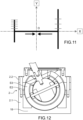
- the housing 2 in which the housing 18 is arranged comprises a lower part 2.1 made of ferromagnetic material and a part 2.2 made of non-magnetic material, which makes it possible to concentrate the magnetic flux on areas facing the sphere S3, in particular when the latter is in an extreme position such as that shown in the figure. figure 12 .
- the housing 2 in which the housing 18 is arranged comprises a lower part 2.1 made of ferromagnetic material and a part 2.2 made of non-magnetic material, which makes it possible to concentrate the magnetic flux on areas facing the sphere S3, in particular when the latter is in an extreme position such as that shown in the figure. figure 12 .
- the housing 2 in which the housing 18 is arranged comprises a lower part 2.1 made of ferromagnetic material and a part 2.2 made of non-magnetic material, which makes it possible to concentrate the magnetic flux on areas facing the sphere S3, in particular when the latter is in an extreme position such as that shown in the figure. figure 12 .
- the implementation of the magnetorheological fluid and the coil makes it possible to integrate a passive brake into the external pivot joint P2.
- the coil 24 is carried by the housing 18, thus the connection to the electrical source is simplified.
- the coil 24 is carried by the third sphere S3.
- Each Y1 axis is mounted in a bore 28 made in the wall of the third sphere S3 and in a bore 30 made in the housing 18.
- the Y1 axes are fixed in the bores 30 and are mounted in plain bearings 32 housed in the bores 28.
- the second sphere S2 is mounted in the third sphere S3.
- the first, second and third spheres and the housing 18 are made of ferromagnetic material, for example soft iron.
- Magnetic isolation is provided between the two pivot joints P1, P2 to prevent the activation of a coil of one of the pivot joints from having an action on the magnetorheological fluid of the other pivot joint.
- the magnetic isolation is obtained by a non-magnetic envelope 26 forming a spacer between the second sphere S2 and the third sphere S3.
- the envelope 26 is such that it completely envelops the second sphere S2 and also covers the edges of the opening 6 in order to best confine the field lines in the space E1, and to prevent the field lines B1 from circulating in the third sphere or in the fluid not included in the space E1.
- the envelope 26 advantageously ensures the immobilization in rotation of the second sphere S2 in the third sphere S3.
- the envelope 26 comprises radial projections 34 penetrating into the holes 28 of the third sphere S3 ( figure 10 ), housing the Y1 axes.
- the casing 26 is for example made of aluminum or non-conductive plastic material.
- the envelope is advantageously molded or made by 3D printing, in particular when it is made of plastic material. Alternatively, when it is made of metal, the envelope can be machined.
- the sealed confinement of the magnetorheological fluid is achieved by means of a membrane 36 provided with a passage for the passage of the effector and fixed on the effector and on the edges of the opening 22 of the housing 18.
- This membrane has the advantage of not generating friction unlike O-rings.
- the membrane 36 is stretched between the effector and the housing and has elastic properties, it then ensures a function of returning the effector to the rest position.
- the membrane is made of an elastomer material compatible with the magnetorheological fluid, in particular with the oils contained in the magnetorheological fluids.
- the membrane is made of butadiene-acrylonitrile copolymers, also called "nitrile rubbers" designated NBR (Nitrile Butadiene Rubber in English terminology) or EPDM (ethylene-propylene-diene monomer).
- NBR Nonrile Butadiene Rubber in English terminology
- EPDM ethylene-propylene-diene monomer
- the outer edge of the membrane is pinched between the housing and a cover 38, and the effector comprises two parts 4.1 and 4.2 for example secured by screwing, the edge of the passage is then pinched between the two parts 4.1 and 4.2, additional bonding can be envisaged.
- the cover 38 is for example screwed onto the housing 2.
- This arrangement allows for easy and simultaneous filling of the two spaces E1, E2 with the magnetorheological fluid. Then the membrane is put in place. Alternatively, each space is filled with a different fluid and the two spaces are sealed from each other.
- the joint thus produced blocks the rotation of the effector around the Z axis, which advantageously allows the effector to keep the effector in the defined orientation.
- the reference S designates the shear zones of the fluid, i.e. the zones of the spaces E1 and E2 crossed by the field lines B1 and B2 respectively. It can be seen that when the two coils each generate their magnetic flux, there is no magnetic flux leakage. The two brakes are therefore magnetically isolated from each other and can be actuated without having any effect on the other brake.
- the magnetorheological fluid present in spaces E1 and E2 is subjected to a shear phenomenon during the rotation of spheres S1 and S3. Since the viscosity of the magnetorheological fluid at rest is low, the torques exerted on the spheres are almost zero. However, when an electric current passes through the coil of a brake, a magnetic field is generated in its magnetic circuit. The fluid is then crossed in several zones by this magnetic field. Due to the alignment of the ferromagnetic microparticles of the fluid, its viscosity is increased in these areas. This phenomenon creates a resistant force between the fixed and mobile spheres, proportional to the intensity of the control electric current.
- the operation is similar when an electric current passes through the coil 24, a magnetic field B2 is generated in the space E2 and therefore in the magnetorheological fluid contained in the space E2, the apparent viscosity of that increases and a torque proportional to the intensity of the control electric current opposes the rotation of the third sphere S3 around the Y axis.
- the interface includes sensors for knowing the angles of rotation of the spheres around the X and Y directions.
- rotation sensors can be positioned directly on the X1 and Y1 axes.
- the rotation of the effector around the X and Y directions is measured using, for example, arches ARC1 and ARC2 mounted to rotate around the X and Y directions respectively and each comprising a window F1 and F2 through which the effector passes.
- any movement of the effector around the X and Y directions causes the rotation of the arch ARC1 around the X direction and/or of the arch ARC2 around the Y direction.
- Rotation sensors C1 and C2 are, for example, positioned at the ends of the arches articulated on the housing.
- the interface also comprises a sensor for detecting the user's intention to act on the effector, which makes it possible to improve the behavior of the interface, in particular by reducing or even avoiding sticking phenomena.
- the sensor for detecting the user's intention to act comprises, for example, a torque sensor around the X or Y axes and/or a force sensor around the X and Y axes.
- the sensor is, for example, arranged under the housing, between the housing and the frame B on which the interface is fixed.
- the haptic patterns are designed to account for this overall torque difference between the two brakes.
- each space E1 and E2 is filled with a different fluid, in order to have a shear action would be stronger on the X axis to compensate for the difference in size between the two brakes.
- the fluid filling the space E1 would be more concentrated in ferromagnetic particles.
- joints are provided between the spheres to avoid the circulation of the fluid between the two spaces E1 and E2.
- magnetorheological fluid brake has the advantage of being very robust. Indeed, if the force exerted by the operator on the effector is too great against a braking torque, there is no breakage of any part of the system, but a slippage of the mobile spheres following a separation of the chains of particles of the fluid.
- the structure of the two pivot joints are movable along the Z direction, for example to allow a "click", for example on a push button placed under the structure.
- a shorter Y-axis stroke is desired along the foot located at a value of X ⁇ 0 and for values of Y>0 and Y ⁇ 0, compared to the foot located at a value of X>0.
- the limitation of the movement along X and/or Y is obtained by activating the brake(s) so that the braking torque or torques generated are sufficient to block the movement of the effector both around the X axis and around the Y axis.
- the device according to the invention is very compact.
- the housing 2 can have an external diameter of 34 mm and a height of 30 mm. It can thus be relatively easily integrated into mobile controls, such as tablets or joysticks.
- the present invention applies to joystick-type control interfaces which require configuration according to use, for example to joysticks for controlling overhead crane-type machines, handling machines, and to video game controllers, in remote controls for model making.
Landscapes
- Engineering & Computer Science (AREA)
- General Engineering & Computer Science (AREA)
- Theoretical Computer Science (AREA)
- Physics & Mathematics (AREA)
- General Physics & Mathematics (AREA)
- Human Computer Interaction (AREA)
- Automation & Control Theory (AREA)
- Mechanical Control Devices (AREA)
- Fluid-Damping Devices (AREA)
- Manipulator (AREA)
Claims (10)
- Struktur für eine haptische Schnittstelle mit zwei Freiheitsgraden, die beinhaltet:- ein Element zur Wechselwirkung mit dem Benutzer, das dazu bestimmt ist, gemäß zwei Freiheitsgraden beweglich zu sein,- eine erste passive Bremse und eine zweite passive Bremse, die imstande sind, eine Widerstandskraft jeweils um eine erste Achse und eine zweite Achse herum auszuüben,- wobei die erste passive Bremse eine erste Schwenkverbindung (P1) um eine erste Drehrichtung (X) herum beinhaltet, die ein erstes sphärisches Element (S1) beinhaltet, an dem der Effektor (4) befestigt ist, der in einem zweiten sphärischen Element (S2) aufgenommen ist, das eine Aufnahme für das erste sphärische Element (S1) bildet, wobei die Verschiebung des ersten sphärischen Elements (S1) in dem zweiten sphärischen Element (S2) eine Drehung um die erste Drehrichtung (X) herum ist,- wobei die zweite passive Bremse eine zweite Schwenkverbindung um eine zweite Drehrichtung (Y) herum beinhaltet, die ein drittes sphärisches Element (S3) beinhaltet, das mit dem zweiten sphärischen Element (S2) bewegungsverbunden ist, und in einer Aufnahme (18) aufgenommen ist, die eine sphärische Wand (S4) beinhaltet, wobei die Verschiebung des dritten sphärischen Elements (S3) in der Aufnahme (18) eine Drehung um die zweite Drehrichtung (Y) herum ist,- ein erstes Fluid, dessen scheinbare Viskosität sich in Abhängigkeit von einem ersten äußeren Stimulus zwischen dem ersten sphärischen Element (S1) und dem zweiten sphärischen Element (S2) ändert,- ein zweites Fluid, dessen scheinbare Viskosität sich in Abhängigkeit von einem zweiten äußeren Stimulus zwischen dem dritten sphärischen Element (S3) und der Aufnahme (18) ändert,- Mittel zum Erzeugen des ersten und zweiten Stimulus auf Befehl im ersten und zweiten Fluid.
- Struktur nach Anspruch 1, wobei das erste und das zweite Fluid magnetorheoligische Fluide sind, wobei die Mittel zum Erzeugen des ersten und zweiten Stimulus eine erste elektrische Spule (14), die von dem ersten sphärischen Element (S1) oder dem zweiten sphärischen Element (S2) getragen wird, und eine zweite elektrische Spule (24) beinhalten, die von dem dritten Element (S3) oder der Aufnahme (18) getragen wird, und wobei mindestens ein Teil des ersten sphärischen Elements (S1) und ein Teil des zweiten sphärischen Elements (S2) einen ersten Magnetkreis bilden und mindestens ein Teil des dritten sphärischen Elements (S3) und ein Teil der Aufnahme (18) einen zweiten Magnetkreis bilden.
- Struktur nach Anspruch 2, die eine Hülle (26) aus unmagnetischem Material zwischen dem zweiten sphärischen Element (S2) und dem dritten sphärischen Element (S3) beinhaltet, die den ersten Magnetkreis in der ersten Bremse und den zweiten Magnetkreis in der zweiten Bremse isoliert.
- Struktur nach einem der Ansprüche 1 bis 3, die eine erste Achse (X1) beinhaltet, die das erste sphärische Element (S1) durchquert, und deren Enden in dem zweiten sphärischen Element (S2) aufgenommen sind, wobei die erste Achse (X1) koaxial mit der ersten Drehrichtung (X) ist, und zweite ausgerichtete Achsen (Y1), die jeweils zwischen dem dritten sphärischen Element (S3) und der Aufnahme (18) montiert sind, wobei die beiden zweiten Achsen (Y1) koaxial mit der zweiten Drehrichtung (Y) sind.
- Struktur nach Anspruch 2 oder Anspruch 3, in Kombination mit Anspruch 4, wobei die erste Spule (14) im ersten sphärischen Element (S1) ist, und eine elektrische Verbindung der Spule (14) mit einer Stromquelle durch die erste Achse (X1) verläuft.
- Struktur nach einem der Ansprüche 1 bis 5, die ein Gehäuse (2) beinhaltet, das die erste und zweite passive Bremse aufnimmt und eine Öffnung umfasst, aus welcher der Effektor (4) hervorsteht, wobei die Schnittstelle auch eine Membran (36) beinhaltet, die in dichter Form am Rand der Öffnung des Gehäuses und am Effektor befestigt ist, um das erste und zweite Fluid in dem Gehäuse einzusperren.
- Struktur nach dem vorstehenden Anspruch, wobei das erste und das zweite Fluid die gleichen sind und wobei das Füllen der Struktur mit Fluid über die Öffnung des Gehäuses erfolgt.
- Struktur nach Anspruch 6 oder Anspruch 7, wobei die Membran (36) solche elastischen Eigenschaften aufweist, dass sie für eine Rückstellfunktion am Effektor sorgen.
- Haptische Schnittstelle, die beinhaltet:- eine Struktur nach einem der vorstehenden Ansprüche,- Mittel zum Messen einer Position des Elements zur Wechselwirkung mit einem Benutzer,- eine Steuereinheit, die imstande ist, in Abhängigkeit von den Informationen über die Position des Elements zur Wechselwirkung mit dem Benutzer Befehle zu den Bremsen zu senden, sodass die passiven Bremsen Widerstandskräfte gemäß mindestens einem gegebenen haptischen Motiv erzeugen.
- Tragbare Steuerschnittstelle für eine Maschine, die mindestens eine haptische Schnittstelle nach dem vorstehenden Anspruch beinhaltet.
Applications Claiming Priority (2)
| Application Number | Priority Date | Filing Date | Title |
|---|---|---|---|
| FR2013864A FR3118215B1 (fr) | 2020-12-21 | 2020-12-21 | Structure pour interface haptique a deux degrés de liberté |
| PCT/FR2021/052308 WO2022136768A1 (fr) | 2020-12-21 | 2021-12-13 | Structure pour interface haptique a deux degrés de liberté |
Publications (2)
| Publication Number | Publication Date |
|---|---|
| EP4264397A1 EP4264397A1 (de) | 2023-10-25 |
| EP4264397B1 true EP4264397B1 (de) | 2025-02-05 |
Family
ID=74759056
Family Applications (1)
| Application Number | Title | Priority Date | Filing Date |
|---|---|---|---|
| EP21851671.4A Active EP4264397B1 (de) | 2020-12-21 | 2021-12-13 | Struktur für eine haptische schnittstelle mit zwei freiheitsgraden |
Country Status (3)
| Country | Link |
|---|---|
| EP (1) | EP4264397B1 (de) |
| FR (1) | FR3118215B1 (de) |
| WO (1) | WO2022136768A1 (de) |
Families Citing this family (1)
| Publication number | Priority date | Publication date | Assignee | Title |
|---|---|---|---|---|
| DE102023125682A1 (de) * | 2023-09-21 | 2025-03-27 | Karl Storz Se & Co. Kg | Haptische vorrichtung |
Family Cites Families (2)
| Publication number | Priority date | Publication date | Assignee | Title |
|---|---|---|---|---|
| FR2887657B1 (fr) * | 2005-06-27 | 2007-09-07 | Itt Mfg Enterprises Inc | Dispositif a boule de commande des deplacements d'un curseur sur un ecran |
| FR3056315B1 (fr) | 2016-09-21 | 2018-09-28 | Commissariat A L'energie Atomique Et Aux Energies Alternatives | Interface haptique a au moins deux degres de liberte presentant un ressenti haptique ameliore |
-
2020
- 2020-12-21 FR FR2013864A patent/FR3118215B1/fr active Active
-
2021
- 2021-12-13 EP EP21851671.4A patent/EP4264397B1/de active Active
- 2021-12-13 WO PCT/FR2021/052308 patent/WO2022136768A1/fr not_active Ceased
Also Published As
| Publication number | Publication date |
|---|---|
| FR3118215B1 (fr) | 2022-12-09 |
| EP4264397A1 (de) | 2023-10-25 |
| FR3118215A1 (fr) | 2022-06-24 |
| WO2022136768A1 (fr) | 2022-06-30 |
Similar Documents
| Publication | Publication Date | Title |
|---|---|---|
| EP3516483B1 (de) | Haptische schnittstelle mit mindestens zwei freiheitsgraden mit verbessertem haptischem empfinden | |
| EP2277095B1 (de) | Elektromagnetischer betätiger und entsprechende steuerung mit haptischer rückkoppelung | |
| EP4154090A1 (de) | Steuerschnittstelle mit haptischem feedback | |
| FR3010547A1 (fr) | Interface de commande a retour haptique | |
| WO2009133056A1 (fr) | Interface a retour d'effort a sensation ameliorée | |
| FR2831626A1 (fr) | Joint homocinetique fixe notamment destine a une colonne de direction de vehicule automobile | |
| EP4264397B1 (de) | Struktur für eine haptische schnittstelle mit zwei freiheitsgraden | |
| EP3198369B1 (de) | Steuerungsverfahren und -schnittstelle zur haptischen rückmeldung für ein kraftfahrzeug | |
| WO2015150439A2 (fr) | Dispositif de commande passif magnétique | |
| EP2244168B1 (de) | Steuervorrichtung mit haptischer Rückkopplung und entsprechendes Stellglied | |
| EP3198368A1 (de) | Steuerungsverfahren und -schnittstelle zur haptischen rückmeldung für ein kraftfahrzeug | |
| FR3010550B1 (fr) | Procede et interface de commande a retour haptique pour vehicule automobile | |
| WO2005010743A9 (fr) | Peripherique d'entree pour ordinateur ou similaire | |
| FR3084940A1 (fr) | Interface de commande a retour haptique | |
| FR3026501A1 (fr) | Procede et interface de commande a retour haptique pour vehicule automobile | |
| EP3215911A1 (de) | Steuerungsverfahren und -schnittstelle zur haptischen rückmeldung für ein kraftfahrzeug | |
| JP2008076161A (ja) | 荷重センサ | |
| EP3198371B1 (de) | Steuerungsschnittstelle zur haptischen rückmeldung für ein kraftfahrzeug | |
| FR2900086A1 (fr) | Organe de commande a cables tendus | |
| FR2859783A1 (fr) | Organe de manoeuvre | |
| FR2861473A1 (fr) | Dispositif de pointage bi-dimensionnel | |
| WO2016016520A1 (fr) | Interface et procede de commande d'une interface de commande a retour haptique pour vehicule automobile |
Legal Events
| Date | Code | Title | Description |
|---|---|---|---|
| STAA | Information on the status of an ep patent application or granted ep patent |
Free format text: STATUS: UNKNOWN |
|
| STAA | Information on the status of an ep patent application or granted ep patent |
Free format text: STATUS: THE INTERNATIONAL PUBLICATION HAS BEEN MADE |
|
| PUAI | Public reference made under article 153(3) epc to a published international application that has entered the european phase |
Free format text: ORIGINAL CODE: 0009012 |
|
| STAA | Information on the status of an ep patent application or granted ep patent |
Free format text: STATUS: REQUEST FOR EXAMINATION WAS MADE |
|
| 17P | Request for examination filed |
Effective date: 20230621 |
|
| AK | Designated contracting states |
Kind code of ref document: A1 Designated state(s): AL AT BE BG CH CY CZ DE DK EE ES FI FR GB GR HR HU IE IS IT LI LT LU LV MC MK MT NL NO PL PT RO RS SE SI SK SM TR |
|
| DAV | Request for validation of the european patent (deleted) | ||
| DAX | Request for extension of the european patent (deleted) | ||
| GRAP | Despatch of communication of intention to grant a patent |
Free format text: ORIGINAL CODE: EPIDOSNIGR1 |
|
| STAA | Information on the status of an ep patent application or granted ep patent |
Free format text: STATUS: GRANT OF PATENT IS INTENDED |
|
| INTG | Intention to grant announced |
Effective date: 20240902 |
|
| RAP3 | Party data changed (applicant data changed or rights of an application transferred) |
Owner name: COMMISSARIAT A L'ENERGIE ATOMIQUE ET AUX ENERGIESALTERNATIVES |
|
| GRAS | Grant fee paid |
Free format text: ORIGINAL CODE: EPIDOSNIGR3 |
|
| GRAA | (expected) grant |
Free format text: ORIGINAL CODE: 0009210 |
|
| STAA | Information on the status of an ep patent application or granted ep patent |
Free format text: STATUS: THE PATENT HAS BEEN GRANTED |
|
| AK | Designated contracting states |
Kind code of ref document: B1 Designated state(s): AL AT BE BG CH CY CZ DE DK EE ES FI FR GB GR HR HU IE IS IT LI LT LU LV MC MK MT NL NO PL PT RO RS SE SI SK SM TR |
|
| REG | Reference to a national code |
Ref country code: GB Ref legal event code: FG4D Free format text: NOT ENGLISH |
|
| REG | Reference to a national code |
Ref country code: CH Ref legal event code: EP |
|
| REG | Reference to a national code |
Ref country code: IE Ref legal event code: FG4D Free format text: LANGUAGE OF EP DOCUMENT: FRENCH |
|
| REG | Reference to a national code |
Ref country code: DE Ref legal event code: R096 Ref document number: 602021025832 Country of ref document: DE |
|
| REG | Reference to a national code |
Ref country code: NL Ref legal event code: MP Effective date: 20250205 |
|
| PG25 | Lapsed in a contracting state [announced via postgrant information from national office to epo] |
Ref country code: RS Free format text: LAPSE BECAUSE OF FAILURE TO SUBMIT A TRANSLATION OF THE DESCRIPTION OR TO PAY THE FEE WITHIN THE PRESCRIBED TIME-LIMIT Effective date: 20250505 |
|
| PG25 | Lapsed in a contracting state [announced via postgrant information from national office to epo] |
Ref country code: FI Free format text: LAPSE BECAUSE OF FAILURE TO SUBMIT A TRANSLATION OF THE DESCRIPTION OR TO PAY THE FEE WITHIN THE PRESCRIBED TIME-LIMIT Effective date: 20250205 |
|
| PG25 | Lapsed in a contracting state [announced via postgrant information from national office to epo] |
Ref country code: PL Free format text: LAPSE BECAUSE OF FAILURE TO SUBMIT A TRANSLATION OF THE DESCRIPTION OR TO PAY THE FEE WITHIN THE PRESCRIBED TIME-LIMIT Effective date: 20250205 |
|
| PG25 | Lapsed in a contracting state [announced via postgrant information from national office to epo] |
Ref country code: ES Free format text: LAPSE BECAUSE OF FAILURE TO SUBMIT A TRANSLATION OF THE DESCRIPTION OR TO PAY THE FEE WITHIN THE PRESCRIBED TIME-LIMIT Effective date: 20250205 |
|
| REG | Reference to a national code |
Ref country code: LT Ref legal event code: MG9D |
|
| PG25 | Lapsed in a contracting state [announced via postgrant information from national office to epo] |
Ref country code: IS Free format text: LAPSE BECAUSE OF FAILURE TO SUBMIT A TRANSLATION OF THE DESCRIPTION OR TO PAY THE FEE WITHIN THE PRESCRIBED TIME-LIMIT Effective date: 20250605 Ref country code: NO Free format text: LAPSE BECAUSE OF FAILURE TO SUBMIT A TRANSLATION OF THE DESCRIPTION OR TO PAY THE FEE WITHIN THE PRESCRIBED TIME-LIMIT Effective date: 20250505 |
|
| PG25 | Lapsed in a contracting state [announced via postgrant information from national office to epo] |
Ref country code: NL Free format text: LAPSE BECAUSE OF FAILURE TO SUBMIT A TRANSLATION OF THE DESCRIPTION OR TO PAY THE FEE WITHIN THE PRESCRIBED TIME-LIMIT Effective date: 20250205 |
|
| PG25 | Lapsed in a contracting state [announced via postgrant information from national office to epo] |
Ref country code: HR Free format text: LAPSE BECAUSE OF FAILURE TO SUBMIT A TRANSLATION OF THE DESCRIPTION OR TO PAY THE FEE WITHIN THE PRESCRIBED TIME-LIMIT Effective date: 20250205 |
|
| PG25 | Lapsed in a contracting state [announced via postgrant information from national office to epo] |
Ref country code: LV Free format text: LAPSE BECAUSE OF FAILURE TO SUBMIT A TRANSLATION OF THE DESCRIPTION OR TO PAY THE FEE WITHIN THE PRESCRIBED TIME-LIMIT Effective date: 20250205 Ref country code: PT Free format text: LAPSE BECAUSE OF FAILURE TO SUBMIT A TRANSLATION OF THE DESCRIPTION OR TO PAY THE FEE WITHIN THE PRESCRIBED TIME-LIMIT Effective date: 20250605 |
|
| PG25 | Lapsed in a contracting state [announced via postgrant information from national office to epo] |
Ref country code: BG Free format text: LAPSE BECAUSE OF FAILURE TO SUBMIT A TRANSLATION OF THE DESCRIPTION OR TO PAY THE FEE WITHIN THE PRESCRIBED TIME-LIMIT Effective date: 20250205 Ref country code: GR Free format text: LAPSE BECAUSE OF FAILURE TO SUBMIT A TRANSLATION OF THE DESCRIPTION OR TO PAY THE FEE WITHIN THE PRESCRIBED TIME-LIMIT Effective date: 20250506 |
|
| REG | Reference to a national code |
Ref country code: AT Ref legal event code: MK05 Ref document number: 1764991 Country of ref document: AT Kind code of ref document: T Effective date: 20250205 |
|
| PG25 | Lapsed in a contracting state [announced via postgrant information from national office to epo] |
Ref country code: SE Free format text: LAPSE BECAUSE OF FAILURE TO SUBMIT A TRANSLATION OF THE DESCRIPTION OR TO PAY THE FEE WITHIN THE PRESCRIBED TIME-LIMIT Effective date: 20250205 |
|
| PG25 | Lapsed in a contracting state [announced via postgrant information from national office to epo] |
Ref country code: SM Free format text: LAPSE BECAUSE OF FAILURE TO SUBMIT A TRANSLATION OF THE DESCRIPTION OR TO PAY THE FEE WITHIN THE PRESCRIBED TIME-LIMIT Effective date: 20250205 |
|
| PG25 | Lapsed in a contracting state [announced via postgrant information from national office to epo] |
Ref country code: DK Free format text: LAPSE BECAUSE OF FAILURE TO SUBMIT A TRANSLATION OF THE DESCRIPTION OR TO PAY THE FEE WITHIN THE PRESCRIBED TIME-LIMIT Effective date: 20250205 |
|
| PG25 | Lapsed in a contracting state [announced via postgrant information from national office to epo] |
Ref country code: IT Free format text: LAPSE BECAUSE OF FAILURE TO SUBMIT A TRANSLATION OF THE DESCRIPTION OR TO PAY THE FEE WITHIN THE PRESCRIBED TIME-LIMIT Effective date: 20250205 |
|
| PG25 | Lapsed in a contracting state [announced via postgrant information from national office to epo] |
Ref country code: AT Free format text: LAPSE BECAUSE OF FAILURE TO SUBMIT A TRANSLATION OF THE DESCRIPTION OR TO PAY THE FEE WITHIN THE PRESCRIBED TIME-LIMIT Effective date: 20250205 |
|
| PG25 | Lapsed in a contracting state [announced via postgrant information from national office to epo] |
Ref country code: EE Free format text: LAPSE BECAUSE OF FAILURE TO SUBMIT A TRANSLATION OF THE DESCRIPTION OR TO PAY THE FEE WITHIN THE PRESCRIBED TIME-LIMIT Effective date: 20250205 Ref country code: CZ Free format text: LAPSE BECAUSE OF FAILURE TO SUBMIT A TRANSLATION OF THE DESCRIPTION OR TO PAY THE FEE WITHIN THE PRESCRIBED TIME-LIMIT Effective date: 20250205 |
|
| PG25 | Lapsed in a contracting state [announced via postgrant information from national office to epo] |
Ref country code: RO Free format text: LAPSE BECAUSE OF FAILURE TO SUBMIT A TRANSLATION OF THE DESCRIPTION OR TO PAY THE FEE WITHIN THE PRESCRIBED TIME-LIMIT Effective date: 20250205 |
|
| PG25 | Lapsed in a contracting state [announced via postgrant information from national office to epo] |
Ref country code: SK Free format text: LAPSE BECAUSE OF FAILURE TO SUBMIT A TRANSLATION OF THE DESCRIPTION OR TO PAY THE FEE WITHIN THE PRESCRIBED TIME-LIMIT Effective date: 20250205 |
|
| REG | Reference to a national code |
Ref country code: DE Ref legal event code: R097 Ref document number: 602021025832 Country of ref document: DE |
|
| PLBE | No opposition filed within time limit |
Free format text: ORIGINAL CODE: 0009261 |
|
| STAA | Information on the status of an ep patent application or granted ep patent |
Free format text: STATUS: NO OPPOSITION FILED WITHIN TIME LIMIT |
|
| 26N | No opposition filed |
Effective date: 20251106 |