EP4264378B1 - Verfahren zum aufdrucken eines funktionellen elements auf eine uhrkomponente - Google Patents
Verfahren zum aufdrucken eines funktionellen elements auf eine uhrkomponente Download PDFInfo
- Publication number
- EP4264378B1 EP4264378B1 EP21840494.5A EP21840494A EP4264378B1 EP 4264378 B1 EP4264378 B1 EP 4264378B1 EP 21840494 A EP21840494 A EP 21840494A EP 4264378 B1 EP4264378 B1 EP 4264378B1
- Authority
- EP
- European Patent Office
- Prior art keywords
- solution
- receiving area
- sub
- functional element
- particle
- Prior art date
- Legal status (The legal status is an assumption and is not a legal conclusion. Google has not performed a legal analysis and makes no representation as to the accuracy of the status listed.)
- Active
Links
Images

Classifications
-
- C—CHEMISTRY; METALLURGY
- C09—DYES; PAINTS; POLISHES; NATURAL RESINS; ADHESIVES; COMPOSITIONS NOT OTHERWISE PROVIDED FOR; APPLICATIONS OF MATERIALS NOT OTHERWISE PROVIDED FOR
- C09D—COATING COMPOSITIONS, e.g. PAINTS, VARNISHES OR LACQUERS; FILLING PASTES; CHEMICAL PAINT OR INK REMOVERS; INKS; CORRECTING FLUIDS; WOODSTAINS; PASTES OR SOLIDS FOR COLOURING OR PRINTING; USE OF MATERIALS THEREFOR
- C09D11/00—Inks
-
- G—PHYSICS
- G04—HOROLOGY
- G04B—MECHANICALLY-DRIVEN CLOCKS OR WATCHES; MECHANICAL PARTS OF CLOCKS OR WATCHES IN GENERAL; TIME PIECES USING THE POSITION OF THE SUN, MOON OR STARS
- G04B17/00—Mechanisms for stabilising frequency
- G04B17/04—Oscillators acting by spring tension
- G04B17/06—Oscillators with hairsprings, e.g. balance
- G04B17/063—Balance construction
-
- G—PHYSICS
- G04—HOROLOGY
- G04D—APPARATUS OR TOOLS SPECIALLY DESIGNED FOR MAKING OR MAINTAINING CLOCKS OR WATCHES
- G04D3/00—Watchmakers' or watch-repairers' machines or tools for working materials
- G04D3/0069—Watchmakers' or watch-repairers' machines or tools for working materials for working with non-mechanical means, e.g. chemical, electrochemical, metallising, vapourising; with electron beams, laser beams
-
- G—PHYSICS
- G04—HOROLOGY
- G04D—APPARATUS OR TOOLS SPECIALLY DESIGNED FOR MAKING OR MAINTAINING CLOCKS OR WATCHES
- G04D7/00—Measuring, counting, calibrating, testing or regulating apparatus
- G04D7/08—Measuring, counting, calibrating, testing or regulating apparatus for balance wheels
- G04D7/082—Measuring, counting, calibrating, testing or regulating apparatus for balance wheels for balancing
- G04D7/088—Measuring, counting, calibrating, testing or regulating apparatus for balance wheels for balancing by loading the balance wheel itself with material
Definitions
- the invention relates to a method of printing a functional element on a surface of a receiving area of a watch component of a timepiece as well as to such a watch component and to this timepiece.
- these methods conventionally provide in a first step the determination of a correction value to be applied to the inertia of the balance wheel to obtain a desired rate of this movement, said value being determined from the establishment of a measurement of the rate of the movement of the timepiece. And in a second step, they provide the implementation of an addition of material by projection of this material on the balance wheel in order to adjust the inertia of this balance wheel according to the determined correction value.
- An aim of the invention is therefore to propose a method which makes it possible to apply a functional element in a precise and targeted manner to a defined receiving area of a watch component, the component being able in one example to be a balance wheel.
- Another aim of the invention is to thus offer the possibility of being able to adjust a timepiece comprising a resonator equipped with such a balance wheel.
- Another aim of the invention is to print a functional element made of a controlled quantity of material on the receiving area of the watch component.
- the invention relates to a printing method according to the appended claim 1.
- the invention relates to a method for printing a functional element 2 on a receiving surface 5 of a receiving zone 3 of a watch component 1 of a timepiece 100.
- a method is preferably an aerosol jet printing method also known as "aerosol jet”.
- this method can implement other printing technologies of the "high density inkjet” type, pneumatic dosing, dosing by extrusion using an endless screw or even “super inkjet”.
- the method can also implement a printing technology providing for the production of deposits of cords by points using spitting devices such as "micro-drops". With this latter printing technology, these points can be arranged sufficiently close to each other in order to form a functional element 2 in a continuous line.
- Such a method aims in particular at this functional element 2 printed on this surface 5 of the receiving zone 3 being a functional element 2 which therefore finds a functional application only in the field of watchmaking.
- This functional element 2 is for example a decorative/aesthetic element, an element for adjusting/setting the operation of a watch component (for example: an inertial mass), an interface element or even an element for certain identification of the watch component.
- This functional element 2 is formed from a solid material which may comprise, in a non-exhaustive and non-limiting manner, at least one molecular precursor or at least one particle such as a metal or metal oxide particle, a monocrystalline or polycrystalline particle (such as alumina, silicon), a particle of matter amorphous (glass, metal, etc.), a ceramic particle, a polymer particle, a pigmented/colored particle, a colorless particle, a translucent/transparent particle, a fluorescent particle or a phosphorescent particle.
- the particle can be of the nanoparticle or microparticle type.
- the functional element 2 printed on the surface 5 of the receiving zone 3 forms an adjustment/setting element which is of the inertial mass type.
- This inertial mass 2 makes it possible to participate in the adjustment of the running of the timepiece in particular by modifying the inertia and/or the unbalance of a timepiece component 1 of this part 100, here a balance wheel.
- the invention can also make it possible to correct in this context the inertia and/or the unbalance of a balance-spring alone or of a balance-spring mounted in a movement 110 of the timepiece 100, which movement 110 can be mounted in a case of this timepiece during the correction operations. It is understood that all the operations implemented within the framework of the printing process described below remain the same regardless of the type of functional element 2 to be printed on the receiving zone 3.
- reception surface 5 is defined over all or part of the reception zone 3.
- the balance 1 comprises a felloe 11, a hub 12 intended to be pivotally mounted on a balance shaft, and one or more arms 13, for example two, three or four arms 13, connecting the felloe 11 to the hub 12.
- the balance 1 comprises an adjustment face comprising at least one receiving zone 3 intended to receive the functional element 2.
- This adjustment face comprises in particular the upper face 4a and/or the lower face 4d and/or the first lateral face 4b and/or the second lateral face 4c.
- This adjustment face is preferably oriented towards the bottom of the case of the timepiece 100 when the balance 1 is included in the watch movement 110 which is for example mounted in this case, so that each receiving zone 3 is accessible for printing the functional element 2 on their receiving surface 5.
- the upper face 4a comprises a first part included/defined in the rim 11 of the balance 1 and a second part in the arms 13 of this balance 1.
- Such an upper face 4a is flat or substantially flat, and extends in a plane orthogonal to the balance shaft.
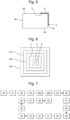
- the receiving area 3 may be a recess such as a groove, a cavity or even a concave structure, being provided with an opening, a solid bottom which may have a substantially flat surface as well as an internal wall connecting said opening to said bottom.
- a solid bottom should be understood here as being a bottom without an opening/orifice.
- the receiving surface 5 is formed by the bottom of this recess as in the figure 3 , or even by the bottom and part of the internal wall as on the figure 4 .
- each recesses are defined only in the upper face 4a of the balance 1, and in particular in the rim 11, this face 4a then comprises several openings giving access to an interior volume of the corresponding recesses.
- each recess and therefore each corresponding interior volume is intended to receive the functional element 2 acting as an inertial mass in order to modify the inertia and/or the unbalance of the balance 1.
- this recess can be through by forming a through hole or even a bottomless hole then comprising an opening at its two ends.
- the receiving surface is formed by the internal wall of this recess.
- the receiving zone 3 is not a recess and can then be defined both on a surface portion of the upper face 4a (or the lower face 4d) and a surface portion of one of the two lateral faces 4b, 4c.
- the receiving zone 3 can be located only on a surface portion of the upper face 4a or the lower face 4d or even a surface portion of the lateral face 4b, 4c.
- the receiving zone 3 can be defined in/on the felloe 11 or one of the arms 13 of the balance 1.
- the balance 1 comprises several receiving zones 3, these can be distributed only in/on the arms 13 of this balance 1 or only in/on the felloe 11 or in/on the arms 13 and the felloe 11 of this balance 1.
- the balance 1 comprises a single receiving zone 3, this can be defined in the adjustment face over the entire contour of the felloe 11.
- the serge 11 comprises several receiving zones 3, for example three zones 3, distributed around the perimeter of the serge 11. Each receiving zone 3 extends along an arc of a circle with an angle of, for example, between 5° and 120° and preferably between 20° and 60°.
- the serge 11 comprises a multitude of receiving zones 3, for example four or more zones 3, which are distributed around the periphery of this serge 11. These receiving zones 3 extend along an arc of a circle with an angle of less than 90° and preferably less than 45°. It is understood that the invention can also be implemented for a serge comprising a single receiving zone 3 or two receiving zones 3 or even more than three receiving zones 3.
- the receiving zones 3 can for example be distributed over this periphery of the rim 11 of the balance 1 in a regular manner so as to obtain a symmetrical distribution of the functional element 2 printed in all the receiving zones 3 or some of them in order to modify the inertia and/or the unbalance of the balance 1 and thus precisely adjust the rate of the movement 110.
- the receiving zones 3 according to the two aforementioned embodiments can, according to another example, be distributed around the rim 11 in an asymmetrical manner in order to modify the inertia and/or the unbalance of the balance 1 and its center of mass by printing the functional element 2 in all or some of the asymmetrical receiving areas 3.
- the receiving areas 3 of the balance 1 are distributed symmetrically on the rim 11 of the balance 1 and the functional element 2 is printed only in some of these receiving areas 3 which have an asymmetrical configuration relative to each other.
- each receiving zone 3 opens onto the adjustment face of the balance wheel 1, this face when it is made up solely of the upper face 4a and/or of the two lateral faces 4b, 4c, is intended to be arranged substantially opposite the back of the case of the timepiece 100 when the watch movement 110 is mounted in this case.
- the projection device is capable of implementing an aerosol jet type printing technology which allows very precise nebulization with a very small volume of material.
- FIG 7 represents the method of printing the functional element 2 on the surface 5 of the receiving zone 3 of the watch component 1 of the timepiece 100. More precisely, in the embodiment of the invention described here, the printing of such a functional element 2 on the watch component 1, the balance 1 or even a sprung balance, participates in carrying out the adjustment of the rate of the timepiece 100. Under these conditions, such a method is also a method of printing, in particular by aerosol jet, the functional element 2 on the surface 5 of the receiving zone 3 of this component 1 of the timepiece 100 contributing to the adjustment of the running of the timepiece 100 in particular by modifying the inertia and/or the unbalance of this component 1.
- Such a method comprises a step 20 of preparing a solution comprising said material constituting the functional element 2 to be printed on the watch component 1.
- a solution may be in a more or less viscous or pasty liquid state.
- this solution comprising this material may then be an ink, i.e. a liquid solution which may be dried by evaporation or cured by polymerization after its deposition on the receiving zone 3 so as to ensure the application of the solid material to said zone 3.
- the definition sub-step 21 comprises a phase 22 of determining said at least one structural modification characteristic of the watch component 1.
- said at least one structural modification characteristic comprises a rate correction value resulting from correction values of the inertia and/or the unbalance of the balance 1 in order to obtain an adjusted/corrected rate of the watch movement 110 and therefore of the timepiece 100.
- this determination phase 22 comprises a sub-phase 23 of measuring the rate of the watch movement 110.
- This measurement can preferably be carried out without contact given that access to the resonator is particularly narrow. In a known manner, the measurement of the rate of the movement 110 can thus be carried out, for example, using optical and/or acoustic technologies.
- This measurement sub-phase 23 makes it possible to compare the measured rate with a desired rate. Furthermore, it also makes it possible to know the beat of the balance 1 in order to be able to synchronize it with the impression of the functional element 2 on the receiving surface 5 of each receiving zone 3 of the balance 1.
- the determination phase 22 then comprises a sub-phase 24a of estimation of the correction value of the inertia of the balance 1 to obtain a corrected rate.
- the determination phase 22 also includes a sub-phase 24b of estimating the correction value of the unbalance of the balance 1 to obtain a corrected rate.
- the estimation of such a correction value is well known in the state of the art and is notably described in the documents WO2012007460 And EP2864844A1 .
- the definition sub-step 21 comprises a phase of determining 25 said at least one construction characteristic of the functional element 2 on said receiving zone 3.
- the construction characteristics such as geometric dimensions and/or mechanical, chemical and/or aesthetic properties of the functional element 2 are determined.
- the geometric dimensions of the functional element 2 which are determined here relate in particular to the thickness, length, width and/or radius of this functional element. 2, allowing to define the value of the gait correction.
- the functional element 2 which is built on the receiving zone can have a rectangular section or a section representing a portion of a disk. This section here depends on the surface tensions of the solution and the receiving surface of the receiving zone 3.
- This definition sub-step 21 also comprises a phase 26 of determining said at least one structural characteristic of the material to be applied to said receiving zone 3.
- the structural characteristics such as aesthetic, physical and/or chemical properties such as the density and surface tension of this material are determined. It will be noted that this density of the material is that of this same material which will constitute the functional element 2 printed on the receiving zone 3 and therefore after the solidification of this element 2 on this zone 3 in particular following the evaporation of a solvent of the solution.
- the definition sub-step 21 also comprises a phase 27 of determining said at least one characteristic of said receiving zone 3 of the component 1.
- the characteristics of the receiving zone 3 such as geometric dimensions of the surface of the receiving zone 3 likely to be covered by the functional element 2 and/or mechanical and/or chemical properties of the material constituting this zone 3 such as properties 5 of adhesion and/or roughness of the surface and/or surface energy and/or surface tension of the surface of this receiving zone 3, are determined.
- Such determination phases referenced 25, 26 and 27 are preferably carried out by experimentation on substrates equivalent to the receiving surface 5 of the receiving zone 3 of the watch component 1 that it is sought to modify.
- Such phases may provide, in a non-limiting and non-exhaustive manner, observation operations under an optical microscope, carrying out adhesion tests, optical or mechanical profilometry, scanning electron microscopy (SEM), dispersive X-ray spectroscopy (EDX), surface energy measurements of the substrate based on reference liquids (e.g. water, ethylene glycol), surface tension measurements of the solutions and/or wettability tests such as measuring the contact angle between the solution and the substrate constituting the receiving zone 3.
- SEM scanning electron microscopy
- EDX dispersive X-ray spectroscopy
- surface energy measurements of the substrate based on reference liquids (e.g. water, ethylene glycol), surface tension measurements of the solutions and/or wettability tests such as measuring the contact angle between the solution and the substrate constituting the receiving zone 3.
- the definition sub-step 21 comprises a generation phase 29 of the specific properties of the solution from said preparation criteria estimated during the preceding determination phases 25, 26, 27, 28.
- these preparation criteria make it possible in particular to determine the quantity and nature of the solid material to be applied to the surface of the receiving zone of the watch component with regard to which, quantity and nature of the material, the viscosity, surface tension and density properties are estimated. It will be noted in particular that the quantity and nature of the material are decisive in particular for the density and viscosity properties and also for the choice of additives which contribute to defining the surface tension of the solution.
- the viscosity property of the solution which is determined from these preparation criteria must be sufficiently large to avoid the spreading, or even the bursting of drops resulting from the projection of the solution beyond the target receiving zone 3 of the printing of this solution.
- This viscosity property is therefore established in consideration of the size of the receiving zone 3 and in certain variants also in consideration of aesthetic criteria relating to the final appearance of the functional element 2.
- the viscosity property of the determined solution defines a viscosity which must be greater than 1 cP, preferably greater than 50 cP.
- this surface tension of the solution is lower than the surface energy of this substrate.
- This condition can be analyzed by measurements of both quantities.
- the surface energy of the substrate can be measured, for example, as a function of the contact angle with reference solvents such as water, ethylene glycol or diiodomethane.
- the surface tension of the solution can be determined, for example, by the hanging drop method.
- the contact angle can be measured directly between the solution and the substrate. In general, one will seek to have good wettability, i.e., a contact angle of approximately between 0° and 90°.
- the property relating to the density of the solution is mainly determined by the mass share of the solid material that composes this solution as well as by the intrinsic density of this material. It is understood that a high density of the solution allows a greater mass contribution to be made fast on the watch component to be treated, which represents an advantage in terms of industrial production. On the other hand, the quantity of solid material also determines the viscosity and in very large quantities, can limit the precision or even the possibility of carrying out the printing.
- the method comprises a step 34 of depositing the prepared solution on the entire surface 5 of the receiving zone 3.
- a step 34 contributes to participating in the construction of the functional element 2 on one or more receiving zones 3 of the balance 1 in order to modify the inertia and/or the unbalance of this balance 1 according to the rate correction value.
- This depositing step 34 comprises a sub-step 35 of applying the prepared solution on the entire surface 5 of the receiving zone 3 of the component 1.
- Such a sub-step 35 participates in the application of the solution comprising the material on the component 1 with a view to constructing the functional element 2.
- Such an application sub-step 35 comprises a phase 36 of transforming the prepared solution into an aerosol when the printing technology is by aerosol jet.
- This phase 36 includes a sub-phase of nebulization 37 of the prepared solution which participates in transforming this solution into an aerosol.
- the deposition step 34 then comprises a sub-step 38 of solidification of the material of the solution applied to the surface of the receiving zone 3.
- This sub-step 38 aims to finalize the construction of this functional element 2 applied to the receiving zone 3 of the component 1.
- This sub-step 38 may consist of continuing the evaporation of the solvent of the solution having started as soon as the application sub-step 35 is implemented, of thermo-setting the material constituting the functional element 2 or of crosslinking this material on the surface 5 of the receiving zone 3.
- this solidification sub-step 38 preferably begins at the same time or substantially at the same time as the application sub-step 35 and ends after the performance of this sub-step. application 35 and this, in order to improve the positioning precision of the functional element 2 in the receiving zone 3.
- the method may provide a reiteration step 39 of the deposition step 34 which is implemented as many times as necessary in order to construct the functional element 2 on the receiving zone 3 of the watch component 1.
- This functional element 2 may be a single piece or be formed of several separate parts such as for example a succession of points separated from each other.
- the method advantageously allows the production of a print of the functional element 2 on this component 1 which is targeted and of great precision.
- positioning it is possible to achieve a centering of the deposits of the order of 5 ⁇ m of precision. This is more limited by the micro-positioning motor system than by the targeting of ejection of the final mixture.
- the quantity of material added it can be controlled in the order of nanograms, well below the sensitivity threshold of watch applications.
Landscapes
- Physics & Mathematics (AREA)
- General Physics & Mathematics (AREA)
- Engineering & Computer Science (AREA)
- Chemical & Material Sciences (AREA)
- Optics & Photonics (AREA)
- Plasma & Fusion (AREA)
- Life Sciences & Earth Sciences (AREA)
- Materials Engineering (AREA)
- Wood Science & Technology (AREA)
- Organic Chemistry (AREA)
- Application Of Or Painting With Fluid Materials (AREA)
- Particle Formation And Scattering Control In Inkjet Printers (AREA)
Claims (15)
- Verfahren zum Drucken eines Funktionselements (2) auf einer Oberfläche (5) einer Aufnahmezone (3) einer Uhrkomponente (1) einer Uhr (100), das zum Einstellen des Gangs der Uhr (100), insbesondere durch die Modifikation der Trägheit und/oder der Unwucht der Komponente (1), beiträgt, wobei das Verfahren die folgenden Schritte umfasst:- Vorbereiten (20) einer Lösung, die ein Material enthält, aus dem das Funktionselement (2) besteht, wobei der Schritt des Vorbereitens (20) einen Unterschritt des Definierens (21) spezifischer Eigenschaften der Lösung in Abhängigkeit von Vorbereitungskriterien umfasst, wobei die Eigenschaften eine Viskosität und eine Oberflächenspannung der Lösung betreffen und die Vorbereitungskriterien Folgendes umfassen:• strukturelle Modifikationsmerkmale der Uhrkomponente (1);• Konstruktionsmerkmale des Funktionselements (2) in der Aufnahmezone (3), wobei diese Merkmale geometrische Abmessungen sowie mechanische, chemische und ästhetische Eigenschaften des zu konstruierenden Funktionselements enthalten,• Strukturmerkmale des Materials, das in die Aufnahmezone aufgetragen werden soll, wobei die Merkmale ästhetische, physikalische und chemische Eigenschaften umfassen, die die Dichte des Materials umfassen, und• Merkmale der Aufnahmezone (3) der Komponente (1), die geometrische Abmessungen der Oberfläche der Aufnahmezone, die durch das Funktionselement abgedeckt werden kann, sowie mechanische und chemische Eigenschaften des Materials, aus dem die Zone besteht, umfassen, wobei die Eigenschaften Haftungs-, Oberflächenrauheits-, Oberflächenenergie- und Oberflächenspannungseigenschaften der Oberfläche der Aufnahmezone enthalten; und- Aufbringen (34) der vorbereiteten Lösung auf die Oberfläche (5) der Aufnahmezone durch eine Sprühvorrichtung,wobei der Unterschritt des Definierens (21) eine Phase des Erzeugens (29) der spezifischen Eigenschaften der Lösung aus den während der Phasen des Bestimmens (22, 25, 26, 27, 28) geschätzten Vorbereitungskriterien umfasst:- strukturelle Modifikationsmerkmale der Uhrkomponente (1);- Konstruktionsmerkmale des Funktionselements (2) in der Aufnahmezone;- Strukturmerkmale des Materials, das in die Aufnahmezone (3) aufgetragen werden soll;- Merkmale der Aufnahmezone (3) der Komponente (1); und- Merkmale, die die im Verfahren implementierte Drucktechnologie betreffen,wobei im Druckverfahren während der Erzeugungsphase (29):- die Viskositätseigenschaft der Lösung anhand der Vorbereitungskriterien bestimmt wird und ausreichend hoch ist, um ein Ausbreiten oder sogar Platzen von Tröpfchen zu verhindern, die durch ein Versprühen der Lösung über die Zielaufnahmezone (3) für das Drucken der Lösung hinaus entstehen, wobei die Viskositätseigenschaft unter Berücksichtigung der Größe der Aufnahmezone (3) und auch unter Berücksichtigung ästhetischer Kriterien hinsichtlich des endgültigen Erscheinungsbilds des Funktionselements (2) festgelegt wird, und- die Oberflächenspannungseigenschaft der Lösung entsprechend der Oberflächenenergie in der Aufnahmezone (3) der Uhrenkomponente angepasst wird, wobei die Oberflächenspannung der Lösung geringer ist als die Oberflächenenergie in der Aufnahmezone (3).
- Verfahren nach dem vorhergehenden Anspruch, dadurch gekennzeichnet, dass der Schritt des Herstellens (20) einen Unterschritt des Zusammensetzens (30) einer Mischung in Bezug auf die Lösung in Abhängigkeit von den definierten spezifischen Eigenschaften der Lösung umfasst, wobei der Unterschritt (30) eine Phase des Herstellens (31) einer Basiszubereitung umfasst, die das Material und eine Basisflüssigkeit, insbesondere ein Lösungsmittel, umfasst.
- Verfahren nach dem vorhergehenden Anspruch, dadurch gekennzeichnet, dass der Unterschritt des Zusammensetzens (30) eine Phase des Auswählens (32) mindestens eines Produkts enthält, das der Basiszubereitung hinzugefügt werden soll, wobei das mindestens eine Produkt aus Folgendem ausgewählt wird:- Zusatzstoffe zur Korrektur der Oberflächenspannung wie beispielsweise Netzmittel, und/oder- Dispergiermittel, die zur Stabilität der Dispersion von Partikeln des festen Materials beitragen.
- Verfahren nach einem der Ansprüche 2 und 3, dadurch gekennzeichnet, dass der Schritt des Vorbereitens (20) der Lösung einen Unterschritt des Mischens (33) mindestens eines ausgewählten Produkts mit der Basiszubereitung umfasst.
- Verfahren nach einem der vorhergehenden Ansprüche, dadurch gekennzeichnet, dass der Schritt des Aufbringens (34) einen Unterschritt des Auftragens (35) der vorbereiteten Lösung auf die gesamte Oberfläche (5) der Aufnahmezone (3) umfasst.
- Verfahren nach dem vorhergehenden Anspruch, dadurch gekennzeichnet, dass der Unterschritt des Auftragens (35) nach einer Drucktechnologie vom Typ "Aerosol-Strahl", "Tintenstrahl mit hoher Dichte", "pneumatisches Dosierdrucken", "Extrusions-Dosierdrucken" oder auch "Super-Inkjet" durchgeführt wird.
- Verfahren nach einem der Ansprüche 5 und 6, dadurch gekennzeichnet, dass der Unterschritt des Auftragens (35) eine Phase des Umwandelns (36) der vorbereiteten Lösung in ein Aerosol umfasst, wenn die Drucktechnologie durch einen Aerosol-Strahl erfolgt.
- Verfahren nach einem der vorhergehenden Ansprüche, dadurch gekennzeichnet, dass der Schritt des Aufbringens (34) einen Unterschritt des Verfestigens (38) des Materials der auf die Oberfläche der Aufnahmezone (3) aufgetragenen Lösung umfasst.
- Verfahren nach dem vorhergehenden Anspruch, dadurch gekennzeichnet, dass der Unterschritt des Verfestigens (38) gleichzeitig oder im Wesentlichen gleichzeitig mit dem Unterschritt des Auftragens (35) beginnt und nach dem Durchführen des Unterschritts des Auftragens (35) endet.
- Verfahren nach einem der vorhergehenden Ansprüche, dadurch gekennzeichnet, dass die spezifischen Eigenschaften des Unterschritts des Definierens (21) auch eine Dichte der Lösung betreffen.
- Verfahren nach einem der vorhergehenden Ansprüche, dadurch gekennzeichnet, dass das Material mindestens einen molekularen Vorläufer oder mindestens ein Teilchen, wie beispielsweise ein Metall- oder Metalloxidteilchen, ein monokristallines oder polykristallines Teilchen, ein Teilchen aus amorphem Material, ein Keramikteilchen, ein Teilchen aus einem Polymer, ein pigmentiertes/farbiges Teilchen, ein farbloses Teilchen, ein lichtdurchlässiges/transparentes Teilchen, ein fluoreszierendes Teilchen oder auch ein phosphoreszierendes Teilchen umfasst.
- Verfahren nach einem der vorhergehenden Ansprüche, dadurch gekennzeichnet, dass das Material mindestens ein Teilchen vom Typ Nanoteilchen oder Mikroteilchen umfasst.
- Verfahren nach einem der vorhergehenden Ansprüche, dadurch gekennzeichnet, dass das Funktionselement (2), das auf die Oberfläche (5) der Aufnahmezone (3) der Uhrkomponente (1) der Uhr (100) auftragen ist, ein dekoratives/ästhetisches Element, ein Element zum Einstellen des Betriebs einer Uhrkomponente, wie beispielsweise eine Trägheitsmasse, oder ein Schnittstellenelement umfasst.
- Verfahren nach einem der vorhergehenden Ansprüche, dadurch gekennzeichnet, dass es ferner einen Schritt des Wiederholens (39) des Schritts des Aufbringens (34) umfasst.
- Verfahren nach einem der vorhergehenden Ansprüche, dadurch gekennzeichnet, dass es ein Verfahren zum Drucken, insbesondere durch einen Aerosol-Strahl, eines Funktionselements (2) auf der Oberfläche (5) einer Aufnahmezone (3) der Komponente (1) der Uhr (100) ist, das zum Einstellen des Gangs der Uhr (100), insbesondere durch die Modifikation der Trägheit und/oder der Unwucht der Komponente (1), beiträgt.
Applications Claiming Priority (2)
| Application Number | Priority Date | Filing Date | Title |
|---|---|---|---|
| EP20215110 | 2020-12-17 | ||
| PCT/EP2021/085992 WO2022129229A1 (fr) | 2020-12-17 | 2021-12-15 | Procédé d'impression d'un élément fonctionnel sur un composant horloger |
Publications (2)
| Publication Number | Publication Date |
|---|---|
| EP4264378A1 EP4264378A1 (de) | 2023-10-25 |
| EP4264378B1 true EP4264378B1 (de) | 2024-11-06 |
Family
ID=73855407
Family Applications (1)
| Application Number | Title | Priority Date | Filing Date |
|---|---|---|---|
| EP21840494.5A Active EP4264378B1 (de) | 2020-12-17 | 2021-12-15 | Verfahren zum aufdrucken eines funktionellen elements auf eine uhrkomponente |
Country Status (6)
| Country | Link |
|---|---|
| US (1) | US12517466B2 (de) |
| EP (1) | EP4264378B1 (de) |
| JP (1) | JP7588724B2 (de) |
| KR (1) | KR102888040B1 (de) |
| CN (1) | CN116583789B (de) |
| WO (1) | WO2022129229A1 (de) |
Families Citing this family (2)
| Publication number | Priority date | Publication date | Assignee | Title |
|---|---|---|---|---|
| JP2024142494A (ja) * | 2023-03-30 | 2024-10-11 | セイコーエプソン株式会社 | 時計用部品および時計用部品の加飾方法 |
| JP2024143053A (ja) * | 2023-03-30 | 2024-10-11 | セイコーエプソン株式会社 | 時計用部品および時計用部品の加飾方法 |
Citations (8)
| Publication number | Priority date | Publication date | Assignee | Title |
|---|---|---|---|---|
| JPH09127261A (ja) * | 1995-11-01 | 1997-05-16 | Kawaguchiko Seimitsu Kk | 時計用文字板 |
| JP2008151616A (ja) * | 2006-12-15 | 2008-07-03 | Seiko Epson Corp | 時計用文字板の製造方法、時計用文字板および時計 |
| JP2008164529A (ja) * | 2006-12-28 | 2008-07-17 | Seiko Epson Corp | 時計用文字板の製造方法、時計用文字板および時計 |
| EP2746243A1 (de) * | 2012-12-21 | 2014-06-25 | Rolex S.A. | Farbige technische Keramikkörper und Verfahren zum Herstellen davon |
| EP3078436A1 (de) * | 2015-04-10 | 2016-10-12 | Cartier International AG | Verfahren zur herstellung einer uhrkomponente |
| EP3273312A1 (de) * | 2016-07-18 | 2018-01-24 | ETA SA Manufacture Horlogère Suisse | Verfahren zur gangeinstellung einer uhr |
| CN111077757A (zh) * | 2019-12-03 | 2020-04-28 | 东莞市晶博光电有限公司 | 一种立体感手表表盘及其制作工艺 |
| CH715513A2 (fr) * | 2018-11-05 | 2020-05-15 | Csem Ct Suisse Delectronique Microtechnique Sa Rech Developpement | Balancier d'une pièce d'horlogerie. |
Family Cites Families (8)
| Publication number | Priority date | Publication date | Assignee | Title |
|---|---|---|---|---|
| CH714952B1 (fr) * | 2007-05-08 | 2019-10-31 | Patek Philippe Sa Geneve | Composant horloger, son procédé de fabrication et application de ce procédé. |
| CH704693B1 (fr) | 2010-07-16 | 2015-08-14 | Eta Sa Manufacture Horlogère Suisse | Procédé d'ajustement de fréquence d'oscillation, et/ou d'ajustement d'inertie, et/ou d'équilibrage d'un composant mobile de mouvement d'horlogerie, ou d'un ensemble balancier-spiral d'horlogerie. |
| US20140035995A1 (en) * | 2010-12-07 | 2014-02-06 | Sun Chemical Corporation | Aerosol jet printable metal conductive inks, glass coated metal conductive inks and uv-curable dielectric inks and methods of preparing and printing the same |
| CN104520775B (zh) | 2012-06-26 | 2017-07-21 | 劳力士有限公司 | 确定振荡器失衡特征的方法 |
| EP3181515A1 (de) | 2015-12-15 | 2017-06-21 | CSEM Centre Suisse d'Electronique et de Microtechnique SA - Recherche et Développement | Uhr aus verbundmaterial und ihr herstellungsverfahren |
| FR3052881B1 (fr) * | 2016-06-21 | 2020-10-02 | Lvmh Swiss Mft Sa | Piece pour mouvement horloger, mouvement horloger, piece d'horlogerie et procede de fabrication d'une telle piece pour mouvement horloger |
| EP3557337A1 (de) * | 2018-04-18 | 2019-10-23 | ETA SA Manufacture Horlogère Suisse | Herstellungsverfahren und -system einer uhr, die mit einem individuellen schmuckelement ausgestattet ist |
| EP3647883B1 (de) * | 2018-11-05 | 2025-01-01 | CSEM Centre Suisse D'electronique Et De Microtechnique SA | Unruh einer uhr |
-
2021
- 2021-12-15 EP EP21840494.5A patent/EP4264378B1/de active Active
- 2021-12-15 KR KR1020237019756A patent/KR102888040B1/ko active Active
- 2021-12-15 WO PCT/EP2021/085992 patent/WO2022129229A1/fr not_active Ceased
- 2021-12-15 CN CN202180081887.XA patent/CN116583789B/zh active Active
- 2021-12-15 US US18/257,452 patent/US12517466B2/en active Active
- 2021-12-15 JP JP2023536413A patent/JP7588724B2/ja active Active
Patent Citations (8)
| Publication number | Priority date | Publication date | Assignee | Title |
|---|---|---|---|---|
| JPH09127261A (ja) * | 1995-11-01 | 1997-05-16 | Kawaguchiko Seimitsu Kk | 時計用文字板 |
| JP2008151616A (ja) * | 2006-12-15 | 2008-07-03 | Seiko Epson Corp | 時計用文字板の製造方法、時計用文字板および時計 |
| JP2008164529A (ja) * | 2006-12-28 | 2008-07-17 | Seiko Epson Corp | 時計用文字板の製造方法、時計用文字板および時計 |
| EP2746243A1 (de) * | 2012-12-21 | 2014-06-25 | Rolex S.A. | Farbige technische Keramikkörper und Verfahren zum Herstellen davon |
| EP3078436A1 (de) * | 2015-04-10 | 2016-10-12 | Cartier International AG | Verfahren zur herstellung einer uhrkomponente |
| EP3273312A1 (de) * | 2016-07-18 | 2018-01-24 | ETA SA Manufacture Horlogère Suisse | Verfahren zur gangeinstellung einer uhr |
| CH715513A2 (fr) * | 2018-11-05 | 2020-05-15 | Csem Ct Suisse Delectronique Microtechnique Sa Rech Developpement | Balancier d'une pièce d'horlogerie. |
| CN111077757A (zh) * | 2019-12-03 | 2020-04-28 | 东莞市晶博光电有限公司 | 一种立体感手表表盘及其制作工艺 |
Also Published As
| Publication number | Publication date |
|---|---|
| EP4264378A1 (de) | 2023-10-25 |
| US12517466B2 (en) | 2026-01-06 |
| CN116583789A (zh) | 2023-08-11 |
| CN116583789B (zh) | 2026-02-13 |
| KR20230098895A (ko) | 2023-07-04 |
| US20240045380A1 (en) | 2024-02-08 |
| WO2022129229A1 (fr) | 2022-06-23 |
| JP2024500715A (ja) | 2024-01-10 |
| KR102888040B1 (ko) | 2025-11-18 |
| JP7588724B2 (ja) | 2024-11-22 |
Similar Documents
| Publication | Publication Date | Title |
|---|---|---|
| EP4264378B1 (de) | Verfahren zum aufdrucken eines funktionellen elements auf eine uhrkomponente | |
| EP2145237B1 (de) | Uhrenkomponente und verfahren zu ihrer herstellung | |
| EP2514094B1 (de) | Thermokompensierter resonator mindestens ersten und zweiten grades | |
| EP2367614B1 (de) | Vorrichtung zur abscheidung einer pulvermischung zur bildung eines objekts mit zusammensetzungsgradienten und darauf bezogenes verfahren | |
| EP3083487B1 (de) | Verfahren zur herstellung einer uhrenkomponente | |
| FR2935178A1 (fr) | Substrat pour support de miroir de poids reduit ainsi que miroir avec support de miroir de poids reduit | |
| WO2019180177A1 (fr) | Procede de fabrication d'un spiral en silicium | |
| WO2013011032A1 (fr) | Ensemble fonctionnel de micromecanique | |
| EP2616235B1 (de) | Verfahren zur herstellung einer segmentierten optischen struktur | |
| EP2395125A1 (de) | Verfahren zur Herstellung eines Teils aus amorphem beschichteten Metall | |
| CH718184A2 (fr) | Procédé d'impression d'un élément fonctionnel sur un composant horloger. | |
| FR2727648A1 (fr) | Procede de fabrication micromecanique de buses pour jets de liquide | |
| EP3647883B1 (de) | Unruh einer uhr | |
| EP3037893B1 (de) | Mikromechanische Komponente oder Uhr mit flexiblem Führungsdraht | |
| EP4312085A1 (de) | Verfahren zur herstellung einer uhrenkomponente | |
| EP0795953B1 (de) | Elektronische Vorrichtung mit integrierter Zeitbasis | |
| CH715513A2 (fr) | Balancier d'une pièce d'horlogerie. | |
| EP3391154A1 (de) | Schwingsystem für eine uhr | |
| CH716696A2 (fr) | Procédé de fabrication de spiraux horlogers. | |
| CH717124A2 (fr) | Procédé de fabrication d'un dispositif à lames flexibles monobloc en silicium, notamment pour l'horlogerie. | |
| EP2581794A1 (de) | Funktionelle Mikromechanikanordnung | |
| EP4564105A1 (de) | Verfahren zur herstellung einer unruh | |
| HK40091637A (zh) | 用於在钟表部件上印刷功能元件的方法 | |
| EP3983138A1 (de) | Abscheidungsverfahren | |
| EP2549339A1 (de) | Mikromechanische Funktionsanordnung |
Legal Events
| Date | Code | Title | Description |
|---|---|---|---|
| STAA | Information on the status of an ep patent application or granted ep patent |
Free format text: STATUS: UNKNOWN |
|
| STAA | Information on the status of an ep patent application or granted ep patent |
Free format text: STATUS: THE INTERNATIONAL PUBLICATION HAS BEEN MADE |
|
| PUAI | Public reference made under article 153(3) epc to a published international application that has entered the european phase |
Free format text: ORIGINAL CODE: 0009012 |
|
| STAA | Information on the status of an ep patent application or granted ep patent |
Free format text: STATUS: REQUEST FOR EXAMINATION WAS MADE |
|
| 17P | Request for examination filed |
Effective date: 20230717 |
|
| AK | Designated contracting states |
Kind code of ref document: A1 Designated state(s): AL AT BE BG CH CY CZ DE DK EE ES FI FR GB GR HR HU IE IS IT LI LT LU LV MC MK MT NL NO PL PT RO RS SE SI SK SM TR |
|
| P01 | Opt-out of the competence of the unified patent court (upc) registered |
Effective date: 20231109 |
|
| DAV | Request for validation of the european patent (deleted) | ||
| DAX | Request for extension of the european patent (deleted) | ||
| GRAP | Despatch of communication of intention to grant a patent |
Free format text: ORIGINAL CODE: EPIDOSNIGR1 |
|
| STAA | Information on the status of an ep patent application or granted ep patent |
Free format text: STATUS: GRANT OF PATENT IS INTENDED |
|
| INTG | Intention to grant announced |
Effective date: 20240726 |
|
| GRAS | Grant fee paid |
Free format text: ORIGINAL CODE: EPIDOSNIGR3 |
|
| GRAA | (expected) grant |
Free format text: ORIGINAL CODE: 0009210 |
|
| STAA | Information on the status of an ep patent application or granted ep patent |
Free format text: STATUS: THE PATENT HAS BEEN GRANTED |
|
| AK | Designated contracting states |
Kind code of ref document: B1 Designated state(s): AL AT BE BG CH CY CZ DE DK EE ES FI FR GB GR HR HU IE IS IT LI LT LU LV MC MK MT NL NO PL PT RO RS SE SI SK SM TR |
|
| REG | Reference to a national code |
Ref country code: GB Ref legal event code: FG4D Free format text: NOT ENGLISH |
|
| REG | Reference to a national code |
Ref country code: CH Ref legal event code: EP |
|
| REG | Reference to a national code |
Ref country code: DE Ref legal event code: R096 Ref document number: 602021021601 Country of ref document: DE |
|
| REG | Reference to a national code |
Ref country code: IE Ref legal event code: FG4D Free format text: LANGUAGE OF EP DOCUMENT: FRENCH |
|
| REG | Reference to a national code |
Ref country code: LT Ref legal event code: MG9D |
|
| REG | Reference to a national code |
Ref country code: NL Ref legal event code: MP Effective date: 20241106 |
|
| PG25 | Lapsed in a contracting state [announced via postgrant information from national office to epo] |
Ref country code: IS Free format text: LAPSE BECAUSE OF FAILURE TO SUBMIT A TRANSLATION OF THE DESCRIPTION OR TO PAY THE FEE WITHIN THE PRESCRIBED TIME-LIMIT Effective date: 20250306 Ref country code: HR Free format text: LAPSE BECAUSE OF FAILURE TO SUBMIT A TRANSLATION OF THE DESCRIPTION OR TO PAY THE FEE WITHIN THE PRESCRIBED TIME-LIMIT Effective date: 20241106 Ref country code: PT Free format text: LAPSE BECAUSE OF FAILURE TO SUBMIT A TRANSLATION OF THE DESCRIPTION OR TO PAY THE FEE WITHIN THE PRESCRIBED TIME-LIMIT Effective date: 20250306 |
|
| PG25 | Lapsed in a contracting state [announced via postgrant information from national office to epo] |
Ref country code: NL Free format text: LAPSE BECAUSE OF FAILURE TO SUBMIT A TRANSLATION OF THE DESCRIPTION OR TO PAY THE FEE WITHIN THE PRESCRIBED TIME-LIMIT Effective date: 20241106 Ref country code: FI Free format text: LAPSE BECAUSE OF FAILURE TO SUBMIT A TRANSLATION OF THE DESCRIPTION OR TO PAY THE FEE WITHIN THE PRESCRIBED TIME-LIMIT Effective date: 20241106 |
|
| REG | Reference to a national code |
Ref country code: AT Ref legal event code: MK05 Ref document number: 1740023 Country of ref document: AT Kind code of ref document: T Effective date: 20241106 |
|
| PG25 | Lapsed in a contracting state [announced via postgrant information from national office to epo] |
Ref country code: BG Free format text: LAPSE BECAUSE OF FAILURE TO SUBMIT A TRANSLATION OF THE DESCRIPTION OR TO PAY THE FEE WITHIN THE PRESCRIBED TIME-LIMIT Effective date: 20241106 |
|
| PG25 | Lapsed in a contracting state [announced via postgrant information from national office to epo] |
Ref country code: ES Free format text: LAPSE BECAUSE OF FAILURE TO SUBMIT A TRANSLATION OF THE DESCRIPTION OR TO PAY THE FEE WITHIN THE PRESCRIBED TIME-LIMIT Effective date: 20241106 |
|
| PG25 | Lapsed in a contracting state [announced via postgrant information from national office to epo] |
Ref country code: NO Free format text: LAPSE BECAUSE OF FAILURE TO SUBMIT A TRANSLATION OF THE DESCRIPTION OR TO PAY THE FEE WITHIN THE PRESCRIBED TIME-LIMIT Effective date: 20250206 |
|
| PG25 | Lapsed in a contracting state [announced via postgrant information from national office to epo] |
Ref country code: LV Free format text: LAPSE BECAUSE OF FAILURE TO SUBMIT A TRANSLATION OF THE DESCRIPTION OR TO PAY THE FEE WITHIN THE PRESCRIBED TIME-LIMIT Effective date: 20241106 Ref country code: GR Free format text: LAPSE BECAUSE OF FAILURE TO SUBMIT A TRANSLATION OF THE DESCRIPTION OR TO PAY THE FEE WITHIN THE PRESCRIBED TIME-LIMIT Effective date: 20250207 Ref country code: AT Free format text: LAPSE BECAUSE OF FAILURE TO SUBMIT A TRANSLATION OF THE DESCRIPTION OR TO PAY THE FEE WITHIN THE PRESCRIBED TIME-LIMIT Effective date: 20241106 |
|
| PGFP | Annual fee paid to national office [announced via postgrant information from national office to epo] |
Ref country code: CH Payment date: 20250101 Year of fee payment: 4 |
|
| PG25 | Lapsed in a contracting state [announced via postgrant information from national office to epo] |
Ref country code: PL Free format text: LAPSE BECAUSE OF FAILURE TO SUBMIT A TRANSLATION OF THE DESCRIPTION OR TO PAY THE FEE WITHIN THE PRESCRIBED TIME-LIMIT Effective date: 20241106 |
|
| PG25 | Lapsed in a contracting state [announced via postgrant information from national office to epo] |
Ref country code: RS Free format text: LAPSE BECAUSE OF FAILURE TO SUBMIT A TRANSLATION OF THE DESCRIPTION OR TO PAY THE FEE WITHIN THE PRESCRIBED TIME-LIMIT Effective date: 20250206 |
|
| PG25 | Lapsed in a contracting state [announced via postgrant information from national office to epo] |
Ref country code: SM Free format text: LAPSE BECAUSE OF FAILURE TO SUBMIT A TRANSLATION OF THE DESCRIPTION OR TO PAY THE FEE WITHIN THE PRESCRIBED TIME-LIMIT Effective date: 20241106 |
|
| PG25 | Lapsed in a contracting state [announced via postgrant information from national office to epo] |
Ref country code: DK Free format text: LAPSE BECAUSE OF FAILURE TO SUBMIT A TRANSLATION OF THE DESCRIPTION OR TO PAY THE FEE WITHIN THE PRESCRIBED TIME-LIMIT Effective date: 20241106 |
|
| PG25 | Lapsed in a contracting state [announced via postgrant information from national office to epo] |
Ref country code: EE Free format text: LAPSE BECAUSE OF FAILURE TO SUBMIT A TRANSLATION OF THE DESCRIPTION OR TO PAY THE FEE WITHIN THE PRESCRIBED TIME-LIMIT Effective date: 20241106 |
|
| PG25 | Lapsed in a contracting state [announced via postgrant information from national office to epo] |
Ref country code: RO Free format text: LAPSE BECAUSE OF FAILURE TO SUBMIT A TRANSLATION OF THE DESCRIPTION OR TO PAY THE FEE WITHIN THE PRESCRIBED TIME-LIMIT Effective date: 20241106 |
|
| PG25 | Lapsed in a contracting state [announced via postgrant information from national office to epo] |
Ref country code: SK Free format text: LAPSE BECAUSE OF FAILURE TO SUBMIT A TRANSLATION OF THE DESCRIPTION OR TO PAY THE FEE WITHIN THE PRESCRIBED TIME-LIMIT Effective date: 20241106 |
|
| PG25 | Lapsed in a contracting state [announced via postgrant information from national office to epo] |
Ref country code: CZ Free format text: LAPSE BECAUSE OF FAILURE TO SUBMIT A TRANSLATION OF THE DESCRIPTION OR TO PAY THE FEE WITHIN THE PRESCRIBED TIME-LIMIT Effective date: 20241106 |
|
| PG25 | Lapsed in a contracting state [announced via postgrant information from national office to epo] |
Ref country code: IT Free format text: LAPSE BECAUSE OF FAILURE TO SUBMIT A TRANSLATION OF THE DESCRIPTION OR TO PAY THE FEE WITHIN THE PRESCRIBED TIME-LIMIT Effective date: 20241106 |
|
| REG | Reference to a national code |
Ref country code: DE Ref legal event code: R097 Ref document number: 602021021601 Country of ref document: DE |
|
| PG25 | Lapsed in a contracting state [announced via postgrant information from national office to epo] |
Ref country code: LU Free format text: LAPSE BECAUSE OF NON-PAYMENT OF DUE FEES Effective date: 20241215 |
|
| PG25 | Lapsed in a contracting state [announced via postgrant information from national office to epo] |
Ref country code: SE Free format text: LAPSE BECAUSE OF FAILURE TO SUBMIT A TRANSLATION OF THE DESCRIPTION OR TO PAY THE FEE WITHIN THE PRESCRIBED TIME-LIMIT Effective date: 20241106 |
|
| PLBE | No opposition filed within time limit |
Free format text: ORIGINAL CODE: 0009261 |
|
| STAA | Information on the status of an ep patent application or granted ep patent |
Free format text: STATUS: NO OPPOSITION FILED WITHIN TIME LIMIT |
|
| PG25 | Lapsed in a contracting state [announced via postgrant information from national office to epo] |
Ref country code: MC Free format text: LAPSE BECAUSE OF FAILURE TO SUBMIT A TRANSLATION OF THE DESCRIPTION OR TO PAY THE FEE WITHIN THE PRESCRIBED TIME-LIMIT Effective date: 20241106 |
|
| REG | Reference to a national code |
Ref country code: BE Ref legal event code: MM Effective date: 20241231 |
|
| 26N | No opposition filed |
Effective date: 20250807 |
|
| PG25 | Lapsed in a contracting state [announced via postgrant information from national office to epo] |
Ref country code: BE Free format text: LAPSE BECAUSE OF NON-PAYMENT OF DUE FEES Effective date: 20241231 |
|
| PG25 | Lapsed in a contracting state [announced via postgrant information from national office to epo] |
Ref country code: IE Free format text: LAPSE BECAUSE OF NON-PAYMENT OF DUE FEES Effective date: 20241215 |
|
| REG | Reference to a national code |
Ref country code: CH Ref legal event code: R17 Free format text: ST27 STATUS EVENT CODE: U-0-0-R10-R17 (AS PROVIDED BY THE NATIONAL OFFICE) Effective date: 20251203 |
|
| REG | Reference to a national code |
Ref country code: CH Ref legal event code: U11 Free format text: ST27 STATUS EVENT CODE: U-0-0-U10-U11 (AS PROVIDED BY THE NATIONAL OFFICE) Effective date: 20260101 |
|
| PGFP | Annual fee paid to national office [announced via postgrant information from national office to epo] |
Ref country code: DE Payment date: 20251126 Year of fee payment: 5 |
|
| PGFP | Annual fee paid to national office [announced via postgrant information from national office to epo] |
Ref country code: GB Payment date: 20251119 Year of fee payment: 5 |
|
| PGFP | Annual fee paid to national office [announced via postgrant information from national office to epo] |
Ref country code: FR Payment date: 20251120 Year of fee payment: 5 |