EP4264024B1 - Reinigungsvorrichtung und verfahren zum reinigen einer filteranordnung - Google Patents
Reinigungsvorrichtung und verfahren zum reinigen einer filteranordnung Download PDFInfo
- Publication number
- EP4264024B1 EP4264024B1 EP21805868.3A EP21805868A EP4264024B1 EP 4264024 B1 EP4264024 B1 EP 4264024B1 EP 21805868 A EP21805868 A EP 21805868A EP 4264024 B1 EP4264024 B1 EP 4264024B1
- Authority
- EP
- European Patent Office
- Prior art keywords
- arrangement
- pipe
- filter
- cleaning
- fluid
- Prior art date
- Legal status (The legal status is an assumption and is not a legal conclusion. Google has not performed a legal analysis and makes no representation as to the accuracy of the status listed.)
- Active
Links
Images


Classifications
-
- F—MECHANICAL ENGINEERING; LIGHTING; HEATING; WEAPONS; BLASTING
- F01—MACHINES OR ENGINES IN GENERAL; ENGINE PLANTS IN GENERAL; STEAM ENGINES
- F01N—GAS-FLOW SILENCERS OR EXHAUST APPARATUS FOR MACHINES OR ENGINES IN GENERAL; GAS-FLOW SILENCERS OR EXHAUST APPARATUS FOR INTERNAL-COMBUSTION ENGINES
- F01N3/00—Exhaust or silencing apparatus having means for purifying, rendering innocuous, or otherwise treating exhaust
- F01N3/02—Exhaust or silencing apparatus having means for purifying, rendering innocuous, or otherwise treating exhaust for cooling, or for removing solid constituents of, exhaust
- F01N3/021—Exhaust or silencing apparatus having means for purifying, rendering innocuous, or otherwise treating exhaust for cooling, or for removing solid constituents of, exhaust by means of filters
-
- B—PERFORMING OPERATIONS; TRANSPORTING
- B01—PHYSICAL OR CHEMICAL PROCESSES OR APPARATUS IN GENERAL
- B01D—SEPARATION
- B01D41/00—Regeneration of the filtering material or filter elements outside the filter for liquid or gaseous fluids
- B01D41/04—Regeneration of the filtering material or filter elements outside the filter for liquid or gaseous fluids of rigid self-supporting filtering material
-
- F—MECHANICAL ENGINEERING; LIGHTING; HEATING; WEAPONS; BLASTING
- F01—MACHINES OR ENGINES IN GENERAL; ENGINE PLANTS IN GENERAL; STEAM ENGINES
- F01N—GAS-FLOW SILENCERS OR EXHAUST APPARATUS FOR MACHINES OR ENGINES IN GENERAL; GAS-FLOW SILENCERS OR EXHAUST APPARATUS FOR INTERNAL-COMBUSTION ENGINES
- F01N3/00—Exhaust or silencing apparatus having means for purifying, rendering innocuous, or otherwise treating exhaust
-
- F—MECHANICAL ENGINEERING; LIGHTING; HEATING; WEAPONS; BLASTING
- F01—MACHINES OR ENGINES IN GENERAL; ENGINE PLANTS IN GENERAL; STEAM ENGINES
- F01N—GAS-FLOW SILENCERS OR EXHAUST APPARATUS FOR MACHINES OR ENGINES IN GENERAL; GAS-FLOW SILENCERS OR EXHAUST APPARATUS FOR INTERNAL-COMBUSTION ENGINES
- F01N3/00—Exhaust or silencing apparatus having means for purifying, rendering innocuous, or otherwise treating exhaust
- F01N3/02—Exhaust or silencing apparatus having means for purifying, rendering innocuous, or otherwise treating exhaust for cooling, or for removing solid constituents of, exhaust
- F01N3/021—Exhaust or silencing apparatus having means for purifying, rendering innocuous, or otherwise treating exhaust for cooling, or for removing solid constituents of, exhaust by means of filters
- F01N3/023—Exhaust or silencing apparatus having means for purifying, rendering innocuous, or otherwise treating exhaust for cooling, or for removing solid constituents of, exhaust by means of filters using means for regenerating the filters, e.g. by burning trapped particles
- F01N3/0237—Exhaust or silencing apparatus having means for purifying, rendering innocuous, or otherwise treating exhaust for cooling, or for removing solid constituents of, exhaust by means of filters using means for regenerating the filters, e.g. by burning trapped particles for regenerating ex situ
Definitions
- the filter assembly is positioned above the receiving chamber such that the first fluid connection points toward the receiving chamber.
- the first fluid connection points toward the exhaust side.
- the second fluid connection is the one that faces the diesel engine when the filter assembly is installed. This ensures that the contaminants present in the filter assembly are expelled from the filter assembly against the operating flow direction of the filter assembly—that is, from bottom to top in the prior art.
- the filter assembly is then removed from the first cleaning device and clamped into a second cleaning device.
- a liquid stream is introduced into the downstream surface of the filter device at a flow rate of more than 50 l/min.
- the liquid is first collected in a collecting chamber
- a cleaning fluid is heated.
- a separate compressed air tank is also provided, capable of delivering a pressure range from 2 bar to 6 bar.
- the compressed air tank and the collection chamber are connected via valves to a channel leading to the downstream side of the filter assembly. The valves are configured to alternately supply cleaning fluid or air.
- the gas-liquid mixture is passed through the filter device from top to bottom.
- the filter arrangement is consequently arranged such that the second fluid connection, which is the upstream connection (facing the diesel engine) of the filter arrangement, is at the bottom, i.e., below the first fluid connection in the direction of gravity.
- the filter arrangement is therefore also cleaned according to the countercurrent principle, in that the gas-liquid mixture is passed through the filter device opposite to the normal filtering direction.
- the introduction of the gas into the receiving chamber preferably also takes place below the liquid level in the receiving chamber, preferably in a region of the lower third of the liquid, seen in the direction of the center of gravity.
- the filter device is essentially dry, or at least not filled with liquid, before the gas-liquid mixture is forced through the filter device under pressure.
- the filter device is essentially dry, or at least not filled with liquid, before the gas-liquid mixture is forced through the filter device under pressure.
- Another particular advantage of the cleaning device according to the invention is that the surface of the filter device on the side of the second fluid connection can be pretreated, in particular precleaned, via the second pipe arrangement without the need to re-clamp the filter arrangement.
- the filter arrangement can be completely cleaned in the cleaning device while it is arranged between the first pipe connection and the second pipe connection.
- Pre-cleaning of the lower side of the filter device on the side of the second fluid connection can be performed in any way.
- pre-cleaning can include combustion.
- a fluid spray device is arranged in the second pipe arrangement, which has at least one spray nozzle directed towards the filter device.
- the surface of the filter device on the side of the second fluid connection can be pre-cleaned by spraying a spray fluid, which can be water.
- a cleaning agent which can be soap-like, can also be mixed into the spray fluid.
- the fluid spray device is preferably designed such that it can clean not only the surface of the filter device, but also a peripheral region thereof, in particular a region of a flange section, within which contaminants such as ash, soot, etc. can also accumulate.
- the filter arrangement in the region of the second fluid connection can therefore be cleaned in advance such that no further post-cleaning is required after the subsequent cleaning using the gas-liquid mixture.
- the fluid spray device has a spray bar which extends transversely to a longitudinal direction and on which a plurality of spray nozzles are arranged.
- the spray device is rotatable about a longitudinal axis.
- the second pipe arrangement preferably has a siphon-like pipe section in which spray fluid and contaminants can collect, which are detached from the filter device by means of the fluid spray device.
- the siphon-like pipe section has a drain through which spray fluid and impurities can be removed from the second pipe arrangement.
- the drain is preferably arranged in a lower region of the siphon-like pipe section, so that after the pre-cleaning by means of the fluid spray device, there are essentially no large amounts of contaminants removed by the pre-cleaning in the siphon-like pipe section.
- the first pipe arrangement is displaceable in a longitudinal direction in order to facilitate insertion of the filter arrangement between the first pipe connection and the second pipe connection.
- the section of the first tube arrangement can be manually displaceable in the longitudinal direction.
- the longitudinal direction is preferably parallel to the direction of gravity.
- the force can be controlled via suitable software, so that the first adjustment motor is controlled accordingly.
- a spring arrangement can generally also be arranged between a drive element of the first adjustment motor and the first tube assembly to enable the first tube connection to be placed on the first filter connection in a force-controlled manner.
- the loading arrangement is preferably designed in the manner of a horizontally movable carriage, onto which a filter arrangement is placed laterally next to the second pipe connection can be placed on top and then moved into a position (cleaning position) above the second pipe connection using the slide.
- the second adjustment motor can also be an electric motor.
- the second adjustment motor can be a linear drive that can move a filter holder or a carriage to which the filter holder is attached horizontally.
- the linear drive can be a conventional electric motor with a rotation-translation converter, but can also be an electric linear motor.
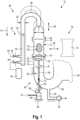
- FIG. 1 An embodiment of a cleaning device is shown schematically and generally designated 10.
- a filter device 18 is arranged, which includes a plurality of longitudinal channels 20.
- a filter device 18 is arranged, which includes a plurality of longitudinal channels 20.
- the cleaning device 10 comprises a housing 28.
- a generator device 30 is arranged on the housing 28, in particular displaceably arranged, as will be explained below.
- the generator device 30 has a receiving chamber 32 for receiving a quantity of liquid, wherein the liquid can be water, in particular, to which additives can be added, as described in the document DE 10 2015 112 939 A1 described.
- the compressed gas generating device 34 is connected to a lower portion of the receiving chamber 32 via a gas valve 36.
- the receiving chamber 32 in particular a lower portion thereof, is connected to a supply of cleaning fluid 40 (in particular water) via a liquid valve 38.
- the first pipe arrangement 44 has a deflection pipe section 48 which initially runs vertically upwards above the receiving chamber 32, counter to a direction of gravity G, then has a U-shaped section and further includes a section (not designated in more detail) from the U-shaped section to the first pipe connection 46, which section leads downwards from the U-shaped section parallel to the direction of gravity G to the first pipe connection 46.
- the cross-section or cross-sectional area of the first tube arrangement 44 may be constant, but is preferably designed such that the first tube arrangement 44 has a first cross-section Q1 in the region adjacent to the receiving chamber 32 which is smaller than a second cross-section Q2 which the first tube arrangement 44 has in a region adjacent to the first tube connection 46.
- the cleaning device 10 further includes a second pipe assembly 50, which includes a second pipe connection 52.
- the second pipe connection 52 is configured to be connected to the second fluid connection of the filter assembly 12.
- the second pipe arrangement 50 is connected at its other end to a collecting device 54, which may, for example, include a droplet separator, similar to that described in the document DE 10 2015 112 939 A1 described.
- the second pipe arrangement 50 has a siphon-like pipe section 56, At its lower end, an outlet 58 is provided through which fluid can be drained.
- a pump 60 is integrated into the outlet 58.
- Fig. 1 the filter assembly 12 is shown in a cleaning position in which it is connected with its second fluid connection 16 to the second pipe connection 52, and in which the first fluid connection 14 is sealingly connected to the first pipe connection 46.
- cleaning can be performed by means of the cleaning device in such a way that fluid is first poured into the receiving chamber 32 until the fluid reaches a certain liquid level 42. Subsequently, the gas valve 36 is opened, so that a blast of compressed air is introduced into the lower region of the receiving chamber 32, so that the fluid contained in the receiving chamber 32 is swirled or foamed and expelled toward the first pipe connection 46, namely via the deflection pipe section 48.
- the gas-liquid mixture then penetrates the filter device 18 under high pressure and at high velocity, passes through the filter device 18, and carries with it any contaminants.
- the gas-liquid mixture then exits the surface 22 and enters the second pipe arrangement 50, where it is guided via the siphon-like pipe section 56 to the collecting device 54, where the gas-liquid mixture can expand.
- the liquid contained therein is collected via a droplet separator, allowing for environmentally friendly post-processing of the collected gas-liquid mixture, which contains contaminants.
- a plurality of such cleaning pulses can be performed. Subsequently, at least one drying pulse can also be performed, during which gas is introduced into the empty collection chamber 32.
- the filter arrangement 12 is clamped in such a way that, viewed in the direction of gravity G, the second fluid connection 16 is arranged below the first fluid connection 14.
- a fluid spray device 62 is provided.
- the fluid spray device 62 has a drive shaft 64 that penetrates a wall of the second pipe arrangement 50 via a rotary union 65.
- a supply device 66 located outside the second pipe arrangement 50 serves to drive the drive shaft 64, which extends in the longitudinal direction parallel to the direction of gravity, by means of a drive motor 68.
- the spray fluid 72 may penetrate slightly into the longitudinal channels 20 from the side of the surface 22, but immediately drips downward again.
- the cleaning device 10 may include a loading assembly 78 for moving filter assemblies 12 from outside the cleaning device 10 into a cleaning position in which the filter assembly 12 is arranged between the pipe connections 46, 52. This may be done by means of a second adjusting motor 82.
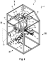
- a lifting plate 92 is mounted on the housing 28 so as to be displaceable in the direction of gravity G. That section of the first pipe arrangement 44 which extends towards the first pipe connection 46 (and which has the slightly larger cross-section Q2), is fixed to the lifting plate 92.
- the lifting plate 92 can be driven in the vertical direction.
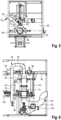
- a drive shaft of the first adjustment motor 80 is connected to a transfer case 96.
- the transfer case 96 is connected via further spindles to a first angular gear 98, which drives a first lifting rod 99 in the vertical direction, and is connected via a further spindle to a second angular gear 100, which drives a second lifting rod 101 parallel to the first lifting rod 99.
- the two lifting rods 99, 101 are connected to the lifting plate 92 in order to be able to drive the first tube arrangement 44 in the vertical longitudinal direction.
- a second bearing plate 104 is fixed to the housing 28 below the first bearing plate 90.
- the second tube assembly 50 is attached to the second bearing plate 104 such that the second tube connection 52 is located above the second bearing plate 104.
- the loading arrangement 78 is arranged on the second bearing plate 104.
- the second bearing plate 104 and the first bearing plate 90 can be connected to each other via a carrier plate 107, as is particularly shown in Fig. 6 is shown.
- a cage 94 is arranged between the first bearing plate 90 and the second bearing plate 104, which cage at least partially surrounds the area of the pipe connections 46, 52.
- the loading assembly 78 includes a linear actuator 108 that drives a loading rod 110 in a horizontal direction, with the loading rod 110 extending through the cage 94.
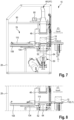
- the loading assembly 78 can be moved into a loading position L1, in which a filter holder 112, which is connected to the loading rod 110, is arranged laterally next to the pipe connections 46, 52 in order to be able to conveniently place a filter assembly 12 thereon for cleaning.
- the linear drive 108 which forms the second adjustment motor 82, can be driven such that the filter holder 112 is moved in the direction towards the pipe connections 46, 52 until the filter arrangement 12 is arranged exactly therebetween in a cleaning position L2.
- the fluid spray device 62 can be deactivated again so that no more spray fluid is supplied and the spray bar 74 no longer rotates.
- At least one cleaning pulse can be performed, in which, as described above, a gas-liquid mixture is generated and forced from above through the filter assembly 12. Furthermore, at least one drying pulse can be performed.
- the first adjustment motor 80 can be driven again to lift the first pipe connection 46 from the first fluid connection 14, so that the Fig. 7 shown position is reached.
- the loading arrangement 78 can then be driven so that the loading position L1 is established again, so that a cleaned filter arrangement 12 can be removed from the cleaning device 10 and another filter arrangement 12 to be cleaned can be inserted.
Landscapes
- Engineering & Computer Science (AREA)
- Chemical & Material Sciences (AREA)
- Combustion & Propulsion (AREA)
- Mechanical Engineering (AREA)
- General Engineering & Computer Science (AREA)
- Chemical Kinetics & Catalysis (AREA)
- Filtering Of Dispersed Particles In Gases (AREA)
- Processes For Solid Components From Exhaust (AREA)
Applications Claiming Priority (2)
| Application Number | Priority Date | Filing Date | Title |
|---|---|---|---|
| DE102020133470.2A DE102020133470B4 (de) | 2020-12-15 | 2020-12-15 | Reinigungsvorrichtung und Verfahren zum Reinigen einer Filteranordnung |
| PCT/EP2021/080025 WO2022128226A1 (de) | 2020-12-15 | 2021-10-28 | Reinigungsvorrichtung und verfahren zum reinigen einer filteranordnung |
Publications (3)
| Publication Number | Publication Date |
|---|---|
| EP4264024A1 EP4264024A1 (de) | 2023-10-25 |
| EP4264024B1 true EP4264024B1 (de) | 2025-03-19 |
| EP4264024C0 EP4264024C0 (de) | 2025-03-19 |
Family
ID=78592817
Family Applications (1)
| Application Number | Title | Priority Date | Filing Date |
|---|---|---|---|
| EP21805868.3A Active EP4264024B1 (de) | 2020-12-15 | 2021-10-28 | Reinigungsvorrichtung und verfahren zum reinigen einer filteranordnung |
Country Status (11)
| Country | Link |
|---|---|
| US (1) | US12109521B2 (enExample) |
| EP (1) | EP4264024B1 (enExample) |
| JP (1) | JP7566160B2 (enExample) |
| CN (1) | CN116685760B (enExample) |
| CA (1) | CA3205415A1 (enExample) |
| DE (1) | DE102020133470B4 (enExample) |
| HU (1) | HUE070853T2 (enExample) |
| MA (1) | MA60478B1 (enExample) |
| MX (1) | MX2023006989A (enExample) |
| PL (1) | PL4264024T3 (enExample) |
| WO (1) | WO2022128226A1 (enExample) |
Families Citing this family (2)
| Publication number | Priority date | Publication date | Assignee | Title |
|---|---|---|---|---|
| DE102024128004A1 (de) | 2024-09-26 | 2026-03-26 | Atc Waldenburg Gmbh | Reinigungsvorrichtung und Verfahren zum Reinigen einer Filteranordnung |
| CN119163494B (zh) * | 2024-11-18 | 2025-04-18 | 上海锐孜动力机器有限公司 | 一种柴油发电机组用的消烟装置 |
Family Cites Families (28)
| Publication number | Priority date | Publication date | Assignee | Title |
|---|---|---|---|---|
| FR2794992B1 (fr) * | 1999-06-17 | 2003-04-04 | Peugeot Citroen Automobiles Sa | Procede et dispositif de nettoyage d'un filtre a particules et procede de traitement d'effluents produits lors du nettoyage |
| CZ300623B6 (cs) | 2000-10-31 | 2009-07-01 | Faurecia Systemes D'echappement | Zpusob cištení prívodní plochy filtru na zachycování cástic a zarízení k provádení tohoto zpusobu |
| JP3534724B2 (ja) * | 2001-09-19 | 2004-06-07 | 三菱重工業株式会社 | フィルタの洗浄装置及び洗浄方法 |
| EP1336729A1 (de) | 2002-02-14 | 2003-08-20 | Zeuna-Stärker Gmbh & Co Kg | Verfahren und Vorrichtung zum Entfernen von Rückständen aus dem Filterkörper des Partikelfilters der Abgasanlage eines Verbrennungsmotors |
| JP4447822B2 (ja) * | 2002-05-20 | 2010-04-07 | ホソカワミクロン株式会社 | フィルタの洗浄方法 |
| US7025811B2 (en) * | 2002-08-23 | 2006-04-11 | Cleaire Advanced Emission Controls | Apparatus for cleaning a diesel particulate filter with multiple filtration stages |
| ES2284805T3 (es) | 2002-12-19 | 2007-11-16 | Utisol Technologies Ag | Dispositivo de filtro. |
| US20050011357A1 (en) * | 2003-07-14 | 2005-01-20 | Crawley Wilbur H. | Method and system for flushing ash from a diesel particulate filter |
| US7410529B2 (en) * | 2004-10-05 | 2008-08-12 | Caterpillar Inc. | Filter service system and method |
| US7410530B2 (en) * | 2005-03-04 | 2008-08-12 | Donaldson Company, Inc. | Apparatus for cleaning exhaust aftertreatment devices and methods |
| US20080083334A1 (en) | 2006-10-06 | 2008-04-10 | Pronob Bardhan | Method and system for removing ash from a filter |
| WO2008054262A1 (en) * | 2006-10-31 | 2008-05-08 | Volvo Lastvagnar Ab | Device for cleaning a diesel particulate filter |
| US8256060B2 (en) * | 2007-01-30 | 2012-09-04 | Donaldson Company, Inc. | Apparatus for cleaning exhaust aftertreatment devices and methods |
| US8206492B2 (en) * | 2007-08-29 | 2012-06-26 | Waldo Cole L | Method and apparatus for cleaning diesel particulate filters and for diagnosing damage thereto |
| US20100037423A1 (en) * | 2008-07-10 | 2010-02-18 | Herman John T | Apparatus for Cleaning Exhaust Aftertreatment Devices and Methods |
| GB2472104B (en) | 2009-07-25 | 2011-09-07 | Eminox Ltd | Cleaning a vehicle exhaust filter |
| IT1403687B1 (it) | 2011-02-07 | 2013-10-31 | Rizzitano | Apparato e metodo per la rigenerazione di filtri antiparticolato usati. |
| US20150000701A1 (en) * | 2011-10-20 | 2015-01-01 | Mark TEVELEY | Method and apparatus for cleaning diesel particulate filters |
| WO2015001375A1 (en) * | 2013-07-02 | 2015-01-08 | Renault Trucks | Cleaning assembly |
| CN106103925A (zh) * | 2014-01-07 | 2016-11-09 | 洁净技术股份有限公司 | 用于清洁过滤器、尤其是微粒过滤器的装置和方法 |
| DE102014017860A1 (de) | 2014-12-03 | 2016-06-09 | Hydac Process Technology Gmbh | Filtervorrichtung, Hydrauliksystem und Rückspülverfahren |
| DE102015112939A1 (de) | 2015-08-06 | 2017-02-09 | Mack Gmbh | Dieselpartikelfilter-Reinigungsverfahren und -vorrichtung |
| WO2017048315A1 (en) | 2015-09-15 | 2017-03-23 | Fsx Equipment, Inc. | Apparatus and method for cleaning diesel particulate filters |
| CN106968761B (zh) * | 2017-04-25 | 2020-06-30 | 江铃汽车集团公司 | 自生负压柴油机动车尾气颗粒捕捉装置 |
| BG67125B1 (bg) * | 2017-06-08 | 2020-08-17 | Саани Исметов Денкчиев | Устройство и метод за почистване на филтри за твърди частици и катализатори |
| KR102085073B1 (ko) * | 2018-06-01 | 2020-03-05 | 임진섭 | 배기가스 후처리장치의 세척방법 및 세척장치 |
| CN111561373B (zh) | 2019-02-14 | 2023-01-03 | 康明斯有限公司 | 用于清洁颗粒过滤器的系统和方法 |
| JP6765111B1 (ja) | 2020-06-16 | 2020-10-07 | 有限会社シージーエム | Pm除去ユニット洗浄装置およびpm除去ユニット洗浄方法 |
-
2020
- 2020-12-15 DE DE102020133470.2A patent/DE102020133470B4/de active Active
-
2021
- 2021-10-28 MA MA60478A patent/MA60478B1/fr unknown
- 2021-10-28 CN CN202180084846.6A patent/CN116685760B/zh active Active
- 2021-10-28 JP JP2023535885A patent/JP7566160B2/ja active Active
- 2021-10-28 EP EP21805868.3A patent/EP4264024B1/de active Active
- 2021-10-28 WO PCT/EP2021/080025 patent/WO2022128226A1/de not_active Ceased
- 2021-10-28 CA CA3205415A patent/CA3205415A1/en active Pending
- 2021-10-28 HU HUE21805868A patent/HUE070853T2/hu unknown
- 2021-10-28 PL PL21805868.3T patent/PL4264024T3/pl unknown
- 2021-10-28 MX MX2023006989A patent/MX2023006989A/es unknown
-
2023
- 2023-06-13 US US18/209,038 patent/US12109521B2/en active Active
Also Published As
| Publication number | Publication date |
|---|---|
| WO2022128226A1 (de) | 2022-06-23 |
| HUE070853T2 (hu) | 2025-07-28 |
| JP2023552877A (ja) | 2023-12-19 |
| JP7566160B2 (ja) | 2024-10-11 |
| DE102020133470B4 (de) | 2023-12-21 |
| CN116685760A (zh) | 2023-09-01 |
| DE102020133470A1 (de) | 2022-06-15 |
| CN116685760B (zh) | 2024-09-20 |
| MA60478A1 (fr) | 2023-10-31 |
| EP4264024C0 (de) | 2025-03-19 |
| MX2023006989A (es) | 2023-09-06 |
| MA60478B1 (fr) | 2024-04-30 |
| US12109521B2 (en) | 2024-10-08 |
| CA3205415A1 (en) | 2022-06-23 |
| US20230347269A1 (en) | 2023-11-02 |
| PL4264024T3 (pl) | 2025-06-23 |
| EP4264024A1 (de) | 2023-10-25 |
Similar Documents
| Publication | Publication Date | Title |
|---|---|---|
| EP2212036B1 (de) | Reinigungsverfahren | |
| EP4264024B1 (de) | Reinigungsvorrichtung und verfahren zum reinigen einer filteranordnung | |
| EP2609310B1 (de) | Verfahren und vorrichtung zur reinigung von verkokten hohlräumen, insbesondere von einlasskanälen und ventilen eines verbrennungsmotors | |
| WO2008019995A2 (de) | Brennerreinigungsvorrichtung | |
| EP3226996B1 (de) | Filtervorrichtung, hydrauliksystem und rückspülverfahren | |
| DE19837569A1 (de) | Verfahren zur Reinigung von Filterkerzen eines Kerzenfilters | |
| DE102008024583B4 (de) | Verfahren zum Betrieb einer Filtereinrichtung und Filtereinrichtung | |
| EP3530364A1 (de) | Hochdruckreinigungsvorrichtung für endlosmaterial | |
| EP3127596B1 (de) | Dieselpartikelfilter-reinigungsverfahren | |
| DE3240186C2 (de) | Vorrichtung zum Reinigen von Tanks | |
| DE102005034634B3 (de) | Verfahren und Werkzeug zur Reinigung von Kavitäten | |
| EP3769895A1 (de) | Vorrichtung und verfahren zum reibpunktschweissen | |
| DE19744435C2 (de) | Vorrichtung zum Erhöhen der Oberflächenfestigkeit von metallischen Komponenten | |
| DE102006050127A1 (de) | Filtervorrichtung | |
| EP0720694A1 (de) | Absaugverfahren und vorrichtungen hierfür | |
| DE102024128004A1 (de) | Reinigungsvorrichtung und Verfahren zum Reinigen einer Filteranordnung | |
| WO2000051709A2 (de) | Reinigungsvorrichtung | |
| EP1626792B1 (de) | Verfahren und vorrichtung zur reinigung von schmelzfiltern | |
| DE19701010A1 (de) | Verfahren zur Sanierung der Innenwände festverlegter Rohrleitungen | |
| DE20110009U1 (de) | Vorrichtung zur Reinigung der Oberfläche eines Drahtes | |
| DE102023130183B3 (de) | Reinigungsdüse, Set, Verwendung einer Reinigungsdüse und Verfahren zur Nachrüstung einer Druckluftleitung | |
| DE102015111861B3 (de) | Vorrichtung zum Kühlen oder Schmieren von spanabhebenden Werkzeugen und/oder von Werkstücken | |
| DE102007043745A1 (de) | Verfahren zum Abscheiden von flüssigen und/oder festen Emissionen aus Öl enthaltendem Rohgas, insbesondere bei Maschinen zum Druckumformen, insbesondere bei Warmfließpressen | |
| DE102004058275A1 (de) | Reinigungsvorrichtung | |
| DE10320476B4 (de) | Vorrichtung und Verfahren zum Reinigen von Werkstücken |
Legal Events
| Date | Code | Title | Description |
|---|---|---|---|
| STAA | Information on the status of an ep patent application or granted ep patent |
Free format text: STATUS: UNKNOWN |
|
| STAA | Information on the status of an ep patent application or granted ep patent |
Free format text: STATUS: THE INTERNATIONAL PUBLICATION HAS BEEN MADE |
|
| PUAI | Public reference made under article 153(3) epc to a published international application that has entered the european phase |
Free format text: ORIGINAL CODE: 0009012 |
|
| STAA | Information on the status of an ep patent application or granted ep patent |
Free format text: STATUS: REQUEST FOR EXAMINATION WAS MADE |
|
| 17P | Request for examination filed |
Effective date: 20230712 |
|
| AK | Designated contracting states |
Kind code of ref document: A1 Designated state(s): AL AT BE BG CH CY CZ DE DK EE ES FI FR GB GR HR HU IE IS IT LI LT LU LV MC MK MT NL NO PL PT RO RS SE SI SK SM TR |
|
| DAV | Request for validation of the european patent (deleted) | ||
| DAX | Request for extension of the european patent (deleted) | ||
| STAA | Information on the status of an ep patent application or granted ep patent |
Free format text: STATUS: EXAMINATION IS IN PROGRESS |
|
| 17Q | First examination report despatched |
Effective date: 20240409 |
|
| GRAP | Despatch of communication of intention to grant a patent |
Free format text: ORIGINAL CODE: EPIDOSNIGR1 |
|
| STAA | Information on the status of an ep patent application or granted ep patent |
Free format text: STATUS: GRANT OF PATENT IS INTENDED |
|
| INTG | Intention to grant announced |
Effective date: 20240619 |
|
| GRAJ | Information related to disapproval of communication of intention to grant by the applicant or resumption of examination proceedings by the epo deleted |
Free format text: ORIGINAL CODE: EPIDOSDIGR1 |
|
| STAA | Information on the status of an ep patent application or granted ep patent |
Free format text: STATUS: EXAMINATION IS IN PROGRESS |
|
| GRAP | Despatch of communication of intention to grant a patent |
Free format text: ORIGINAL CODE: EPIDOSNIGR1 |
|
| STAA | Information on the status of an ep patent application or granted ep patent |
Free format text: STATUS: GRANT OF PATENT IS INTENDED |
|
| INTG | Intention to grant announced |
Effective date: 20241024 |
|
| GRAS | Grant fee paid |
Free format text: ORIGINAL CODE: EPIDOSNIGR3 |
|
| GRAA | (expected) grant |
Free format text: ORIGINAL CODE: 0009210 |
|
| STAA | Information on the status of an ep patent application or granted ep patent |
Free format text: STATUS: THE PATENT HAS BEEN GRANTED |
|
| AK | Designated contracting states |
Kind code of ref document: B1 Designated state(s): AL AT BE BG CH CY CZ DE DK EE ES FI FR GB GR HR HU IE IS IT LI LT LU LV MC MK MT NL NO PL PT RO RS SE SI SK SM TR |
|
| REG | Reference to a national code |
Ref country code: GB Ref legal event code: FG4D Free format text: NOT ENGLISH |
|
| REG | Reference to a national code |
Ref country code: CH Ref legal event code: EP |
|
| REG | Reference to a national code |
Ref country code: IE Ref legal event code: FG4D Free format text: LANGUAGE OF EP DOCUMENT: GERMAN |
|
| REG | Reference to a national code |
Ref country code: DE Ref legal event code: R096 Ref document number: 502021006993 Country of ref document: DE |
|
| U01 | Request for unitary effect filed |
Effective date: 20250414 |
|
| U07 | Unitary effect registered |
Designated state(s): AT BE BG DE DK EE FI FR IT LT LU LV MT NL PT RO SE SI Effective date: 20250423 |
|
| PG25 | Lapsed in a contracting state [announced via postgrant information from national office to epo] |
Ref country code: RS Free format text: LAPSE BECAUSE OF FAILURE TO SUBMIT A TRANSLATION OF THE DESCRIPTION OR TO PAY THE FEE WITHIN THE PRESCRIBED TIME-LIMIT Effective date: 20250619 |
|
| PG25 | Lapsed in a contracting state [announced via postgrant information from national office to epo] |
Ref country code: NO Free format text: LAPSE BECAUSE OF FAILURE TO SUBMIT A TRANSLATION OF THE DESCRIPTION OR TO PAY THE FEE WITHIN THE PRESCRIBED TIME-LIMIT Effective date: 20250619 |
|
| PG25 | Lapsed in a contracting state [announced via postgrant information from national office to epo] |
Ref country code: HR Free format text: LAPSE BECAUSE OF FAILURE TO SUBMIT A TRANSLATION OF THE DESCRIPTION OR TO PAY THE FEE WITHIN THE PRESCRIBED TIME-LIMIT Effective date: 20250319 |
|
| PG25 | Lapsed in a contracting state [announced via postgrant information from national office to epo] |
Ref country code: GR Free format text: LAPSE BECAUSE OF FAILURE TO SUBMIT A TRANSLATION OF THE DESCRIPTION OR TO PAY THE FEE WITHIN THE PRESCRIBED TIME-LIMIT Effective date: 20250620 |
|
| REG | Reference to a national code |
Ref country code: HU Ref legal event code: AG4A Ref document number: E070853 Country of ref document: HU |
|
| REG | Reference to a national code |
Ref country code: SK Ref legal event code: T3 Ref document number: E 46520 Country of ref document: SK |
|
| RAP4 | Party data changed (patent owner data changed or rights of a patent transferred) |
Owner name: ATC WALDENBURG GMBH |
|
| U1H | Name or address of the proprietor changed after the registration of the unitary effect |
Owner name: ATC WALDENBURG GMBH; DE |
|
| REG | Reference to a national code |
Ref country code: HU Ref legal event code: HC9C Owner name: ATC WALDENBURG GMBH, DE Free format text: FORMER OWNER(S): MACK GMBH, DE |
|
| PG25 | Lapsed in a contracting state [announced via postgrant information from national office to epo] |
Ref country code: SM Free format text: LAPSE BECAUSE OF FAILURE TO SUBMIT A TRANSLATION OF THE DESCRIPTION OR TO PAY THE FEE WITHIN THE PRESCRIBED TIME-LIMIT Effective date: 20250319 |
|
| PG25 | Lapsed in a contracting state [announced via postgrant information from national office to epo] |
Ref country code: ES Free format text: LAPSE BECAUSE OF FAILURE TO SUBMIT A TRANSLATION OF THE DESCRIPTION OR TO PAY THE FEE WITHIN THE PRESCRIBED TIME-LIMIT Effective date: 20250319 |
|
| PG25 | Lapsed in a contracting state [announced via postgrant information from national office to epo] |
Ref country code: IS Free format text: LAPSE BECAUSE OF FAILURE TO SUBMIT A TRANSLATION OF THE DESCRIPTION OR TO PAY THE FEE WITHIN THE PRESCRIBED TIME-LIMIT Effective date: 20250719 |
|
| PGFP | Annual fee paid to national office [announced via postgrant information from national office to epo] |
Ref country code: HU Payment date: 20251027 Year of fee payment: 5 |
|
| U20 | Renewal fee for the european patent with unitary effect paid |
Year of fee payment: 5 Effective date: 20251028 |
|
| PGFP | Annual fee paid to national office [announced via postgrant information from national office to epo] |
Ref country code: GB Payment date: 20251022 Year of fee payment: 5 |
|
| PGFP | Annual fee paid to national office [announced via postgrant information from national office to epo] |
Ref country code: TR Payment date: 20251021 Year of fee payment: 5 |
|
| PGFP | Annual fee paid to national office [announced via postgrant information from national office to epo] |
Ref country code: CZ Payment date: 20251021 Year of fee payment: 5 |
|
| PGFP | Annual fee paid to national office [announced via postgrant information from national office to epo] |
Ref country code: PL Payment date: 20251016 Year of fee payment: 5 |
|
| PLBE | No opposition filed within time limit |
Free format text: ORIGINAL CODE: 0009261 |
|
| STAA | Information on the status of an ep patent application or granted ep patent |
Free format text: STATUS: NO OPPOSITION FILED WITHIN TIME LIMIT |
|
| PGFP | Annual fee paid to national office [announced via postgrant information from national office to epo] |
Ref country code: SK Payment date: 20251020 Year of fee payment: 5 |
|
| REG | Reference to a national code |
Ref country code: CH Ref legal event code: L10 Free format text: ST27 STATUS EVENT CODE: U-0-0-L10-L00 (AS PROVIDED BY THE NATIONAL OFFICE) Effective date: 20260128 |
|
| 26N | No opposition filed |
Effective date: 20251222 |
|
| REG | Reference to a national code |
Ref country code: SK Ref legal event code: TC4A Ref document number: E 46520 Country of ref document: SK Owner name: ATC WALDENBURG GMBH, WALDENBURG, DE Effective date: 20260212 |