EP4263980B1 - Betätigungsbaugruppe zur betätigung eines türverschlusses - Google Patents
Betätigungsbaugruppe zur betätigung eines türverschlusses Download PDFInfo
- Publication number
- EP4263980B1 EP4263980B1 EP21834718.5A EP21834718A EP4263980B1 EP 4263980 B1 EP4263980 B1 EP 4263980B1 EP 21834718 A EP21834718 A EP 21834718A EP 4263980 B1 EP4263980 B1 EP 4263980B1
- Authority
- EP
- European Patent Office
- Prior art keywords
- actuating
- adapter shaft
- driver
- connection
- pin
- Prior art date
- Legal status (The legal status is an assumption and is not a legal conclusion. Google has not performed a legal analysis and makes no representation as to the accuracy of the status listed.)
- Active
Links
Images


Classifications
-
- E—FIXED CONSTRUCTIONS
- E05—LOCKS; KEYS; WINDOW OR DOOR FITTINGS; SAFES
- E05B—LOCKS; ACCESSORIES THEREFOR; HANDCUFFS
- E05B3/00—Fastening knobs or handles to lock or latch parts
-
- E—FIXED CONSTRUCTIONS
- E05—LOCKS; KEYS; WINDOW OR DOOR FITTINGS; SAFES
- E05B—LOCKS; ACCESSORIES THEREFOR; HANDCUFFS
- E05B17/00—Accessories in connection with locks
- E05B17/0004—Lock assembling or manufacturing
-
- E—FIXED CONSTRUCTIONS
- E05—LOCKS; KEYS; WINDOW OR DOOR FITTINGS; SAFES
- E05B—LOCKS; ACCESSORIES THEREFOR; HANDCUFFS
- E05B63/00—Locks or fastenings with special structural characteristics
- E05B63/0056—Locks with adjustable or exchangeable lock parts
-
- E—FIXED CONSTRUCTIONS
- E05—LOCKS; KEYS; WINDOW OR DOOR FITTINGS; SAFES
- E05B—LOCKS; ACCESSORIES THEREFOR; HANDCUFFS
- E05B65/00—Locks or fastenings for special use
- E05B65/0042—For refrigerators or cold rooms
-
- E—FIXED CONSTRUCTIONS
- E05—LOCKS; KEYS; WINDOW OR DOOR FITTINGS; SAFES
- E05B—LOCKS; ACCESSORIES THEREFOR; HANDCUFFS
- E05B15/00—Other details of locks; Parts for engagement by bolts of fastening devices
- E05B15/16—Use of special materials for parts of locks
- E05B15/1635—Use of special materials for parts of locks of plastics materials
-
- E—FIXED CONSTRUCTIONS
- E05—LOCKS; KEYS; WINDOW OR DOOR FITTINGS; SAFES
- E05B—LOCKS; ACCESSORIES THEREFOR; HANDCUFFS
- E05B17/00—Accessories in connection with locks
- E05B17/0075—Insulating, e.g. for limiting heat transfer; Increasing fire-resistance of locks
Definitions
- the present invention relates to an actuating assembly for actuating a handle pin of a door lock, in particular a refrigerator lock, with an actuating element and an adapter shaft for transmitting torques about a connecting axis between the actuating element and the handle pin.
- an actuating device for actuating a door lock, in particular a refrigerator lock, a door with a first actuating element, a second actuating element and a, in particular metallic, push pin for coupling the first actuating element and the second actuating element along a connecting axis with the door lock, as well as a method for mounting such an actuating device on a door leaf.
- the invention is used for operating door locks, which are usually installed inside a door leaf in such a way that they lock the door leaf to the door frame when the door is closed.
- an actuating element such as a door handle, a rotary knob or a rotary lever, is arranged on the outside of the door leaf, which can be moved relative to the door lock.
- a torque is exerted to operate the door lock.
- the actuating element offers a handle for pivoting the unlocked door leaf in the case of a swing door or moving it in the case of a sliding door.
- a handle pin In order to transfer the torque from the actuating element to the door lock, a handle pin is used that runs from the door lock in the direction of the actuating element.
- the handle pin which is usually a square pin, is positively received by a lock nut of the door lock. A rotation of the handle pin caused by the torque around its longitudinal axis, which runs along a connecting axis between the actuating element and the door lock, is thus transferred to the lock nut and the door lock is thus actuated.
- the handle pin in this case extends on the other side of the door lock in the direction of a second actuating element.
- the handle pin also couples the second actuating element along the connecting axis with the door lock, so that a The torque exerted by the actuating element can be transferred to the door lock via the handle pin.
- the handle pin In simple interior doors, the handle pin is connected directly to the actuating element. To do this, a grub screw is screwed into the actuating element at right angles to the handle pin, which clamps the handle pin firmly into the actuating element. This allows for simple but not very durable installation. This means that this connection tends to come loose after several actuation cycles.
- an actuating assembly is used to actuate a push pin instead of a simple actuating element.
- This actuating assembly comprises an actuating element and an adapter shaft for transmitting torques about a connecting axis between the actuating element and the push pin.
- the adapter shaft enables a reliable connection to be made with the pusher pin and at the same time allows for better sealing to prevent convection.
- the adapter shaft forms a stem-like extension of the actuating element.
- the actuating assembly is inserted into a complementarily shaped through hole in the door leaf, which results in better sealing than with a handle pin that deviates geometrically from the shape of the through hole.
- the actuating assembly proves to be bulky. This is particularly true for actuating elements designed as rotary levers, which have a long handle area as a lever for exerting the torque. When packing, transporting and storing, a lot of packaging material and a lot of space are therefore required in relation to the volume of the actuating assembly.
- An actuating assembly is disclosed, the actuating element of which is connected to a sleeve in a rotationally and tensile-resistant manner by a driver.
- the sleeve has a connecting element for a positive connection to the driver of the actuating element.
- the JP 2019 019610 A discloses an actuation assembly which comprises an adapter shaft in addition to a pusher pin and an actuation element.
- the adapter shaft is inserted into the actuation element, with the individual projections of the adapter shaft resting in corresponding recesses in the actuation element.
- the adapter shaft accommodates the pusher pin in such a way that it can transmit torque from the actuation element to it.
- the object of the present invention is therefore to provide an actuating assembly which can be adapted to differently dimensioned push pins and is easier to transport.
- actuating element has a driver for, in particular, detachable, rotationally fixed and tensile-resistant connection of the adapter shaft and the adapter shaft has a connection element for, in particular, positive, Connection to the driver of the actuating element, wherein the driver and/or the connection element has a mushroom-shaped longitudinal profile along the connection axis.
- the actuating element and the adapter shaft form components of the actuating assembly, which are connected to one another in a connected state via the driver and the connecting element. Torques can be transferred from the actuating element to the adapter shaft, which is connected to it in a rotationally fixed manner, via the driver.
- the adapter shaft can in turn transfer these torques to the pusher pin, so that the pusher pin is actuated by the actuating assembly. Since the adapter shaft is also connected to the actuating element in a tensile manner via the driver, tensile forces are also transferred from the actuating element to the adapter shaft. Even if the actuating element is used as a handle for pivoting a door, the adapter shaft can remain connected in a tensile manner.
- the actuating assembly can be adapted to the pusher pin.
- the driver and the connecting element are not connected to one another.
- the actuating element and the adapter shaft can be packaged and transported separately or parallel to one another. In comparison to a conventional actuating assembly, this saves packaging material and space in an environmentally friendly way.
- the actuating assembly can also be returned from the connected state to the non-connected state.
- the actuating element and/or the adapter shaft can each be replaced individually in this way.
- the adapter shaft can be replaced to adapt the actuating assembly to a pusher pin with a different cross-section, or the actuating element can be replaced to adapt the actuating assembly.
- the driver can have a connection means for the rotationally fixed and tension-resistant connection of the adapter shaft.
- the adapter shaft can be easily connected to the driver and thus to the actuating element using the connection means.
- the connection element of the adapter shaft can be connected directly to the connection means of the driver when the actuating assembly is connected.
- the adapter shaft is advantageously designed as a plug-in shaft that can be plugged into the driver and/or pushed onto the driver.
- the design as a plug-in plug-in shaft means that the adapter shaft can be easily connected to the driver by plugging and/or pushing it on.
- the actuating assembly can be converted from the unconnected state to the connected state with an adapter shaft designed as a plug-in shaft, without the need to use tools and/or other connecting means.
- connection element and the driver are designed to complement each other in the manner of interacting fitting connectors.
- the connection element and the driver enable the adapter shaft to be connected to the driver of the actuating element in a simple manner due to their design in the manner of interacting fitting connectors.
- the connection can be made using clamping forces that are purely determined by the fit.
- a connection means of the driver can be designed to complement the connection element, in particular as its negative, in order to design the driver in the manner of a fitting connector.
- the connection element and/or the driver can have undercuts that enable a tensile-strength connection.
- the longitudinal axis of the adapter shaft can run parallel, in particular coaxial, to the connection axis.
- connection element has a connection direction that runs transversely to the connection axis for connecting the adapter shaft to the driver.
- the connection element can be easily connected to the driver along the connection direction.
- the connection direction that runs transversely to the connection axis makes it easy to create a rotationally fixed and tension-resistant connection of the adapter shaft to the driver along the connection axis.
- the connection movement for connecting the adapter shaft to the driver takes place along the connection direction, while the transmission of the torque and an associated rotation of the actuating assembly takes place about the connection axis that runs transversely to the connection direction.
- the connecting element and/or the driver has a transverse channel, in particular a T-shaped one.
- the transverse channel can run transversely to the connection axis, in particular along the connection direction of the connecting element.
- the transverse channel can be designed in such a way that it is undercut along the connection axis, whereby a tensile connection can be achieved in a simple manner. Undercuts along the connection axis can be achieved in a particularly simple manner using a T-shaped transverse channel.
- the adapter shaft has a receiving element for receiving the pusher pin, in particular in a form-fitting manner transversely to the connection axis.
- the adapter shaft can receive the pusher pin using the receiving element in order to transmit torque to it.
- the pusher pin can be received inside the receiving element.
- the pusher pin can be received by the receiving element along the connecting axis in the manner of a linear bearing, in particular free-running.
- the receiving element can receive the pusher pin particularly easily, which simplifies the assembly of the actuating assembly on the pusher pin.
- the receiving element can have an opening that receives the pusher pin, which can be designed in the manner of a blind hole complementary to the cross section of the pusher pin.
- the receiving element can additionally have clamping webs that can exert a clamping force, in particular a radial one, on the pusher pin.
- the additional clamping forces allow the pusher pin to be held in a fixed position in the receiving element along the connecting axis.
- the pusher pin can be pinned to the receiving element transversely to the connection axis.
- the connecting element and the receiving element are arranged at diametrically opposite ends of the adapter shaft. In this way, the entire length of the adapter shaft can be used to connect the actuating element to the pusher pin.
- the adapter shaft has radially extending securing projections for axial position securing during installation in a door.
- the radially extending securing projections can be brought into engagement with a fitting part arranged on the door during installation in order to prevent the actuating assembly and in particular the adapter shaft from slipping out during installation on the door.
- the radially extending securing projections can be arranged opposite one another at regular intervals along the circumference of the adapter shaft and/or along the diameter of the adapter shaft.
- the adapter shaft has a cold barrier.
- the cold barrier can reduce the heat conduction along the connection axis in order to reduce the heat input into a cooling chamber via the actuation assembly.
- the cold barrier is made of a non-metallic material, in particular a plastic, in cross-section to interrupt a thermal bridge.
- the non-metallic material of the cold barrier can have a reduced thermal conductivity compared to the, in particular, metallic, push pin. Since the cold barrier is made of the non-metallic material in cross-section transverse to the connection axis, areas in it can be avoided in which better heat conduction along the connection axis would be possible.
- a thermal bridge in which heat is introduced into the interior of a cooling chamber via the actuation assembly and the push pin, can be interrupted in this way.
- the cold barrier can extend over the entire cross-section of the adapter shaft. In particular the entire adapter shaft can act as a cold barrier between the actuating element and the push pin.
- the adapter shaft has a reinforcement and/or a reinforcing means.
- the reinforcement and/or the reinforcing means can increase the stability of the adapter shaft.
- the reinforcement can consist of rods, wires and/or a wire mesh which is encased in another material, in particular a plastic.
- the reinforcing means can be designed as an end cap, reinforcing band and/or reinforcing ring which surrounds an area of the remaining adapter shaft, in particular circumferentially, for mechanical reinforcement.
- the reinforcement and/or the reinforcing means can be metallic.
- the cold barrier can be designed without reinforcement and/or without reinforcement.
- the reinforcement and/or the reinforcing means cannot extend into the area of the cold barrier, so that no thermal bridge can extend past the cold barrier via the fastening assembly.
- the driver and/or the connection element have a non-circular, in particular oval, cross-section transverse to the connection axis. Due to the non-circular cross-section transverse to the connection axis, the driver and/or the connection element can easily enable a rotationally fixed connection of the adapter shaft to the actuating element.
- a non-circular cross-section can be achieved in a simple manufacturing process in the form of an oval cross-section.
- the driver and/or the connection element has a mushroom-shaped longitudinal profile along the connection axis.
- a mushroom-shaped longitudinal profile enables the driver and/or the connection element to enable a tensile connection of the adapter shaft to the actuating element along the connection axis in a simple manner.
- the mushroom-shaped longitudinal profile can be designed to complement a transverse channel of the connection element and/or the driver.
- the adapter shaft is designed in several parts, in particular in two parts.
- a multi-part adapter shaft can be made from different materials and/or using different manufacturing processes. In this way, different material properties can be combined with one another in the adapter shaft.
- a first shaft part of the adapter shaft can, for example, be an injection-molded part, in particular made of plastic.
- a second shaft part can be made from a metal, in particular cast or milled.
- an actuating device of the type mentioned at the outset it is proposed to achieve the above object that it has an adapter shaft for transmitting torques between the first actuating element and the pusher pin, which, together with the first actuating element, is part of an actuating assembly of the type described above, thereby resulting in the advantages described in connection with the actuating assembly.
- the entire actuating device can be easily adapted to the door lock and/or the door using an exchangeable handle pin and/or an exchangeable adapter shaft.
- the remaining components of the actuating device can remain unchanged and be used for differently designed door locks and/or doors.
- the first actuating element, the second actuating element, the pusher pin and the adapter shaft can be stored in a non-connected state
- the first actuating element, the second actuating element, the pusher pin and/or the adapter shaft can be packed individually or together to save space, in particular lying parallel next to one another, in a compact form, which saves packaging material in an environmentally friendly way.
- the handle pin can be connected in a form-fitting manner to the actuating assembly and the second actuating element.
- the handle pin can easily transmit torques from both the actuating assembly and the second actuating element to the door lock.
- This form-fitting connection can be established when the actuating device is mounted on the door.
- the handle pin can be connected in a form-fitting manner to the actuating assembly and the second actuating element by means of a pin connection running transversely to the connection axis and/or a screw connection running along the connection axis.
- the adapter shaft is connected to the first connection element via the connection element and the driver and is inserted into the door leaf through a first door surface.
- the adapter shaft can be secured to the door leaf, in particular via its securing projections.
- the adapter shaft can be guided through a fitting arranged on the door leaf in such a way that the securing projections are brought into engagement with the fitting and/or engage behind the fitting to secure the axial position along the connecting axis.
- the adapter shaft and in particular the entire actuation assembly can be rotated around the connecting axis relative to the fitting after the adapter shaft has been guided through the fitting.
- the pressure pin can be arranged to pass through a lock nut of the door lock so that the pusher pin can transfer a torque to the door lock.
- the adapter shaft can accommodate the handle pin on one side of the door lock facing the first door surface.
- the handle pin is arranged on the adapter shaft receiving element before the adapter shaft is inserted into the door leaf, in particular if it is positively connected to the adapter shaft.
- the handle pin arranged on the adapter shaft can thus be easily and quickly mounted on the door leaf together with the actuation assembly in the manner of an assembly group.
- the arrangement and in particular the positive connection of the handle pin to the adapter shaft can thus be located inside the door leaf in the assembled state, so that it is not accessible from the outside of the door leaf.
- the handle pin can be easily prevented from coming loose from the adapter shaft due to influences from the outside of the door leaf.
- the handle pin is advantageously selected depending on the thickness of the door leaf. For a thicker door leaf, i.e. a thick door leaf, a longer handle pin can be selected than for a thinner door leaf.
- the actuating device can be adapted to the door leaf during assembly so that there is no gap and/or no play between the door leaf and the mounted actuating device, in particular along the connecting axis.
- the length of the handle pin can be selected such that it does not protrude from the first door surface of the door leaf when the actuating device is assembled.
- the adapter shaft can alternatively or additionally be selected depending on the thickness of the door leaf.
- the length of the adapter shaft together with the length of the handle pin arranged on it then determine the distance along the connecting axis between the first actuating element and the second actuating element.
- handle pin and the adapter shaft can be selected depending on the door lock.
- a handle pin suitable for operating the door lock can be used in the actuating device, which, for example, has a cross-section that is complementary to a lock nut of the door lock.
- an adapter shaft can be selected, the receiving element of which can accommodate this handle pin for the transmission of torque from the first actuating element to the handle pin.
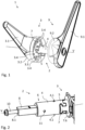
- actuating devices 1 are used, such as the in Fig. 1 shown actuating device 1 according to the invention, which can be used in industrial applications and in particular in cold storage room closures.
- the in Fig. 1 The state of this actuating device 1 shown corresponds to the state which the actuating device 1 assumes after the completed installation on a door. In Fig. 1 Neither the door lock nor the door leaf itself can be seen here, as these are not part of the actuating device 1.
- the actuating device 1 has two actuating elements 3, 9, both of which are designed as rotary levers for manual actuation. Nevertheless, in other embodiments the actuating device 1 can also have differently designed actuating elements 3, 9, which can differ in particular in their type.
- the actuating element 3 could be a door handle and the actuating element 9 could also be a rotary knob.
- the in Fig. 1 The actuating elements 3, 9 shown each have an elongated handle area 3.1, 9.1. These handle areas 3.1, 9.1 make it possible to manually actuate the actuating device 1 from both sides of the door.
- the respective handle area 3.1, 9.1 can be grasped for actuation and used to rotate the actuating element 3, 9 about a connecting axis V between the actuating elements 3, 9 and the door lock (not shown).
- the handle areas 3.1, 9.1 represent a lever with which a high torque about the connecting axis V can be achieved with a relatively low expenditure of force.
- the rotary lever-like actuating elements 3, 9 also each have a connection area 3.2, 9.2, which can rest on the door and via which the two actuating elements 3, 9 are coupled to the door lock.
- the connection area 3.2 is bell-shaped and the The connection area 9.2 is hemispherical, but the connection areas 3.2, 9.2 can also be bell-shaped, hemispherical or pot-shaped in other embodiments, whereby the area around a passage opening through the door, through which the two actuating elements 3, 9 can be connected, is shielded from the outside.
- the rounded shape of the actuating element 3, 9 prevents involuntary hooking and pinching when actuating the actuating device 1. This coupling with the door lock takes place via a Fig. 2 visible pusher pin 8, which can transfer the torques generated by the respective actuating element 3, 9 to the door lock.
- the actuating element 3 also has a driver 7, which enables the connection of an adapter shaft 4 for transmitting torques around the connecting axis V between the actuating element 3 and the pusher pin 8.
- the handle area 3.1 and the connection area 3.2 of the actuating element 3 are manufactured as a one-piece component, in particular an injection-molded component made of plastic
- the Fig. 1 The driver 7 shown is a component of the actuating element 3 that is separate from the handle area 3.1 and the connection area 3.2.
- the driver 7 is arranged in a form-fitting manner on the connection area 3.2 by means of a fixing plate 3.3 through which the driver is guided.
- the fixing plate 3.3 is screwed to the connection area 3.2 in its corner areas using screws 3.4.
- the driver 3 can also be designed as a one-piece component together with the handle area 3.1 and the connection area 3.2.
- the adapter shaft 4 is connected to the actuating element 3 in a rotationally fixed and tensile manner via the driver 7.
- the adapter shaft 4 has a connecting element 5, which is connected to the driver 7 in the connected state of the adapter shaft 4 and the actuating element 3.
- the actuating element 3 can exert tensile forces on the adapter shaft 4 along the connecting axis V and can thus be used, for example, to swing the door open.
- torques can be transmitted between the actuating element 3 and the adapter shaft 4 along the connecting axis V due to the rotationally fixed connection of the adapter shaft 4 to the actuating element 3, without the adapter shaft 4 twisting relative to the actuating element 3.
- the torque transmission between the actuating element 3 and the adapter shaft 4 can thus take place without slippage.
- the actuating element 3 and the adapter shaft 4 are parts of an actuating assembly 2 for actuating the handle pin 8.
- the actuating assembly can be mounted on the door leaf in the manner of a connected assembly element, wherein the adapter shaft 4 is pushed into the door leaf through a door surface and the connection area 3.2 rests against the door leaf.
- actuating assembly 2 and the pusher pin 3 designed as a square pin are shown in more detail, whereby the actuating element 3 is only partially shown and in particular the fixing plate 3.3 is not shown. Due to the absence of the fixing plate 3.3, it can be seen that the driver 7 has a flange 7.6 which, in the assembled state, comes to rest between the fixing plate 3.3 and the connection area 3.2 and via which the fixing plate 3.3 exerts a contact force for arranging the driver 7 on the connection area 3.2.
- connection element 5 and the driver 7 can be designed in the manner of a cooperating The fitting connector can be easily recognized.
- the essentially cylindrical adapter shaft 4 has, in its half along the connecting element side along the connecting axis V, two radially extending securing projections 4.1 that are opposite each other along the diameter of the adapter shaft 4. With these radially extending securing projections 4.1, the adapter shaft can be secured in its position during assembly in the axial direction along the connecting axis V.
- the securing projections are designed in the manner of securing lugs.
- the securing projections 4.1 have a surface that runs essentially transversely to the connection axis V, with which the securing projections 4.1 can, for example, engage behind a fitting part of the door to secure the axial position.
- the surface of the securing projections 4.1 that is opposite this side along the connection axis V is angled relative to the connection axis V, so that the insertion of the adapter shaft 4 into a door leaf is not hindered by the securing projections 4.1.
- the adapter shaft 4 has a receiving element 6 at an end diametrically opposite to the connection element 5.
- This receiving element 6 is shown with the metal pusher pin 8 accommodated therein.
- the receiving element 6 is also designed as a single piece with the other components of the adapter shaft 4.
- the adapter shaft 4 can be designed in a simple manner as an injection-molded part.
- the adapter shaft 4 is additionally pinned to the receiving element 6.
- a fixing pin 11 running transversely to the receiving element 6 and the pusher pin 8 extends radially from the outer surface of the adapter shaft 4 into the pusher pin 8.
- the fixing pin 11 can be, for example, a dowel pin, a spring pin or a wedge pin.
- the pusher pin 8 is connected in a form-fitting manner to the adapter shaft 4 and thus to the actuation assembly 2 via this pin connection.
- the pusher pin 8 In order to be able to connect the pusher pin 8 additionally to the second actuating element 9, the latter has a threaded hole 8.1 on its front side facing away from the actuating assembly 2. As in Fig. 2 As shown, a screw 10 can be screwed into this threaded hole 8.1 through the second actuating element 9, not shown in this figure. A positive connection of the pusher pin 8 with the second actuating element 9 can be established via this screw 10.
- the handle pin 8 is arranged on the adapter shaft 4 via the receiving element 6 before the adapter shaft 4 is inserted into a door leaf and is positively connected by pinning.
- the handle pin 8 is selected from a large number of different handle pins 8 with different cross-sections and/or different lengths before it is arranged on the receiving element 6. From this large number of handle pins 8, the handle pin 8 to be used for installation is selected depending on the thickness of the door leaf. Since the distance between the two actuating elements 3, 9 results from the length of the handle pin 8 and the length of the adapter shaft 4, the distance between the two actuating elements 3, 9 can be adapted to the thickness of the door leaf by selecting a handle pin 8.
- the handle pin 8 is selected depending on the thickness of the door leaf in such a way that, when the actuating device 1 is assembled, a distance corresponding to the thickness of the door leaf along the connecting axis V is established between the actuating elements 3, 9 and in particular the connection areas 3.2, 9.2.
- the actuating device 1 can therefore be adapted to door leaves of different thicknesses.
- Fig. 3 the threaded hole 8.1 of the pusher pin 8 running along the connection axis V can be seen. Also visible is a fastening opening 9.3 of the actuating element 9, which runs along the connection axis V through the entire actuating element 9. The screw 10 for connecting the pusher pin 8 to the actuating element 9 is shown arranged in this fastening opening 9.3.
- the driver 7 is shown separated from the rest of the actuating element 3 and offset transversely to the connection axis V. This arrangement of the driver 7 does not correspond to the position assumed by the driver 7 when the adapter shaft 4 is connected to the actuating element 3, but merely serves to visualize the interaction. During the connection of the adapter shaft 4, the driver 7 rather takes the Fig. 1 shown position as part of the actuating element 3.
- connection means 7.5 of the driver is also provided in Fig. 3
- This connection means 7.5 is designed to be complementary to the shape of the connection element 5 of the adapter shaft 4.
- the connection element 5 has a connection direction A running transversely to the connection axis V.
- the connection element 5 of the adapter shaft 4 has a transverse channel 5.1 running transversely to the connection axis V and parallel to the connection direction A, which partially accommodates the connection means 7.5 along the connection direction when connecting.
- the adapter shaft 4 has a cold barrier 4.2.
- This cold barrier 4.2 interrupts a thermal bridge across the actuating device 1, in which heat would otherwise be transferred by thermal conduction from the door side of one of the two actuating elements 3, 9 to the door side of the other actuating element 9, 3.
- the cold barrier 4.2 is made of a non-metallic material across its entire cross-section. Due to the significantly lower thermal conductivity of plastics compared to the metallic push pin 8, the cold bridge is made of a plastic in particular. Due to this significantly reduced thermal conductivity, heat input through the cold barrier 4.2 is significantly reduced or almost completely suppressed.
- the cold barrier 4.2 is arranged in such a way that a cross-section through the actuating device 1 running transversely to the connection axis V in the area of the cold barrier 4.2 only runs through the material used to produce the cold barrier 4.2. Heat conduction around the cold barrier 4.2 is prevented in this way. Since the adapter shaft 4 in the Fig. 3 shown embodiment is made in one piece from the same material, the entire adapter shaft 4 functions as a cold barrier 4.2.
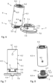
- Fig. 4 the driver 7 and the adapter shaft 4 are shown in more detail in the area of the connecting element 5.
- Fig. 4a and Fig. 4c show the connection element 5 or the driver 7 from a viewing direction opposite to the connection direction A and transverse to the connection axis V.
- Fig. 4b and Fig. 4d show the connection element 5 or the driver 7 each from a perspective along the connection axis V with a view of those end faces of the adapter shaft 4 or the driver 7 which lie against each other in the connected state of these two.
- transverse channel 5.1 running along the connection direction A for connecting the adapter shaft 4 to the driver 7 can be seen.
- the transverse channel 5.1 has an essentially mushroom-like shape, wherein the transverse channel 5.1 essentially has two areas which differ in their respective extent transverse to the connection direction A and transverse to the connection axis V.
- undercuts 5.4 are created in the transverse channel 5.1, which undercut the driver 7 along the connection axis V when the adapter shaft 4 is connected to the driver 7, whereby a tensile-resistant connection of the adapter shaft 4 to the driver 7 is achieved.
- the connecting channel 5.1 can prevent a rotation of the adapter shaft 4 relative to a driver 7 received in a form-fitting manner in the transverse channel 5.1 in order to achieve a rotationally fixed connection of the adapter shaft 4 to the actuating element 3.
- the transverse channel 5.1 runs along more than half the diameter of the connection element 5, in particular along two thirds of the diameter of the connection element 5, so that the transverse channel 5.1 can provide a large contact surface for secure connection to the driver 7.
- connection element 5 has two recesses 5.5 running parallel to the transverse channel 5.1. These recesses 5.5 in the axial edge area of the adapter shaft 4 allow corresponding parts of the actuating element 3 to be accommodated, so that additional stabilization of the rotationally fixed arrangement of the adapter shaft 4 on the actuating element 3 can be achieved.
- Fig. 4a In addition, the arrow-shaped shape of the securing projections 4.1 pointing along the connecting axis V can be clearly seen.
- Fig. 4b This allows a view of the securing surface of the respective securing projection 4.1, which is used for axial position securing and is located at an angle of essentially 90° transverse to the connection axis.
- Fig. 4c and Fig. 4d show the driver 7, wherein in particular the design of the driver 7 complementary to the shape of the connection element 5 can be seen.
- the connection means 7.5 extending from the flange 7.6 along the connection axis V has a cylindrical basic shape, wherein the diameter of the connection means 7.5 corresponds to the diameter of the connection element 5 of the adapter shaft 4.
- the driver 7 has a mushroom-shaped longitudinal profile, which is formed by a stem 7.2 and a head 7.3 connected to it.
- the head 7.3 Transversely to the connection axis V and the connection direction A, the head 7.3 has a larger extension than the stem 7.2 connected to it on the flange side, which corresponds to the essential basic shape of a mushroom.
- the head 7.3 has a web-like geometry with a flat front side facing the adapter shaft 4 when connected.
- the stem 7.2 together with the head 7.3 thus forms a T-shaped area of the driver 7, which is positively received in the complementary T-shaped transverse channel 5.1 of the connection element 5.
- Undercuts 7.4 of the driver 7 can engage behind the connecting element 5 in the connected state and, in particular, with the undercuts 5.4 of the connecting element 5, can serve to connect the adapter shaft 4 to the actuating element 3 in a tension-resistant manner.
- the head 7.3 also has a non-circular cross-section transverse to the connection axis V, as shown in Fig. 4d can be seen.
- the head 7.3 is essentially oval in cross-section, whereby a rotationally fixed connection to the connection element 5 is achieved by inserting the head 7.3 into the transverse channel 5.1. This is because the non-circular shape of the head 7.3 prevents it from twisting in the elongated transverse channel 5.1.
- the driver 7 has two guide lips 7.8, which extend parallel to the connection axis V away from the flange 7.6.
- these guide lips 7.8 serve to guide the connection element 5 along the connection direction A.
- the guide lips 7.8 each engage in a recess 5.5 of the connection element 5 assigned to them.
- the guide lips 7.8, like the recesses 5.5, are designed in the shape of a circular segment, so that the guide lips 7.8 can interact with the recesses 5.5 in a form-fitting manner.
- This form-fitting interaction of the guide lips 7.8 with the recesses 5.5 also enables a rotationally fixed arrangement of the connection element 5 on the driver 7 in the connected state.
- the guide lips 7.8 as well as the recesses 5.5 have two side surfaces that are essentially at right angles to each other and act as stops.
- connection element 5 and the connection means 7.5 which are designed to be complementary to one another, can thus partially engage around one another.
- the flange 7.6 used to arrange the driver 7 has a cylindrical centering element 7.9 on the side opposite the connection means 7.5.
- This centering element 7.9 can be inserted into a centering receptacle (not shown) of the connection area 3.2 in order to be able to position the driver 7 centered at a predetermined position when assembling the actuating element 7.
- the flange 7.6 also has a radially extending orientation recess 7.7. With this orientation recess 7.7, the driver 7 can be arranged in the correct orientation for connecting the adapter shaft 4 to an orientation projection of the connection area 7.2.
- Fig. 5 a second embodiment of the adapter shaft 4 is shown, which with regard to the geometric design of the connecting element 5 and the receiving element 6 corresponds to the Fig. 1 to Fig. 4 shown embodiment. Therefore, this connecting shaft 4 can interact with the same driver 7 as has already been described above.
- the receiving element 6 is also shown without the pusher pin 8 arranged therein.
- the receiving element 6 has a blind hole 6.1 with a square cross-section transverse to the connecting axis V.
- the pusher pin 8 can be freely received by the receiving element 6 along the connecting axis V in the manner of a linear bearing.
- a plurality of clamping webs 6.2 running parallel to the connecting axis and extending into the blind hole 6.1 are arranged in the blind hole 6.1.
- clamping webs 6.2 exert clamping forces directed in the direction of the connecting axis V on the pusher pin 8 arranged in the blind hole 6.1.
- the pusher pin 8 can be arranged in the receiving element in a force-fitting manner via the clamping webs 6.2 along the connecting axis V.
- the latter also has a radially extending pin hole 6.3.
- a fixing pin 11 can be driven into an opening in the pusher pin 8 via the pin hole 6.3, which extends radially from the peripheral outer surface of the connecting element 6 into the blind hole 6.1.
- the receiving element 6 and the pusher pin 8 can be connected to one another in the radial direction via the fixing pin 11, so that the pusher pin 8 is also connected to the receiving element 6 in a form-fitting manner in the axial direction running along the connection axis V.
- the adapter shaft 4 shown is not designed as a single piece, but as a multi-piece.
- the adapter shaft has a first shaft part 4.3 and a second shaft part 4.4.
- the first shaft part 4.3 comprises both the receiving element 6 and the securing projections 4.1 of the adapter shaft 4.
- the first shaft part 4.3 is manufactured as an injection-molded part made of plastic, so that it functions entirely as a cold barrier 4.2.
- the second shaft part 4.4 comprises the connecting element 5, which as in Fig. 4 described. Unlike the first shaft part 4.3, this second shaft part 4.4 is metallic, which increases the mechanical stability when connecting the adapter shaft 4.
- the first shaft part 4.3 made of plastic interrupts the heat conduction between the metal connection element 5 and the pusher pin 8, which is also made of metal.
- the cold barrier 4.2 can also be designed as a further shaft part, which enables a selection adapted to the materials used for the pusher pin 8 and the connection element 5 and an exchange of the cold barrier 4.2 to reduce possible heat input.
- the material of the cold barrier 4.2 can be selected in such a way that its heat conduction is below the other components of the actuating device 1 extending between the actuating elements 3, 9 of the actuating device 1.
- Fig. 6 to Fig. 8 show a third embodiment of the adapter shaft 4 and the driver 7, which differs from the first two embodiments in particular in the geometric design of the connection element 5 and the connection means 7.5.
- the components which are designated with the same reference numerals as in the previous two embodiments do not differ from the components described above with the same reference numerals.
- connection element 5 of the adapter shaft 4 in the Fig. 6 to Fig. 8 does not have a transverse channel 5.1, but has both a stem 5.2 and a head 5.3, which essentially correspond to the above-described stem 7.2 and the above-described head 7.3. Therefore, the connection element 5 in this embodiment with the head 5.3 has a non-circular cross-section transverse to the connection axis V.
- the longitudinal profile of the connection element 5 both transverse to the connection axis V and transverse to the connection direction A is mushroom-shaped and in particular T-shaped.
- connection means 7.5 of the driver 7 has a transverse channel 7.1 running transversely to its longitudinal axis, which in the assembled state runs along the connection axis V.
- connection element 5 of the adapter shaft 4 is inserted into this transverse channel 7.1 along the connection direction A.
- the undercuts 7.4 of the transverse channel 7 interact with the undercuts 5.4 formed by the head 5.3 along the connection axis in such a way that a tensile connection is established.
- the adapter shaft 4 is also designed in several parts.
- Fig. 8 The first shaft part 4.3 and the second shaft part 4.4 are shown spaced apart from each other.
- the first shaft part designed as described is not manufactured as an injection-molded part at a distance from the second shaft part 4.4, but is directly molded onto it in an injection molding process.
- the internal structure of the two shaft parts 4.3, 4.4 described below also corresponds to the Fig. 5 not shown internal structure of the second embodiment of the adapter shaft 4.
- the second shaft part 4.4 has a gating flange 4.5 opposite the connection element 5.
- this gating flange 4.5 forms an axial limitation for the first shaft part 4.3 along the longitudinal axis of the adapter shaft 4, which corresponds to the connection axis V in the connected state.
- the first shaft part 4.3 is molded onto the gating flange 4.5.
- an injection contour 4.6 extends from the injection flange 4.5 in the direction of the first shaft part 4.3. This injection contour increases the contact surface between the first shaft part 4.3 and the second shaft part 4.4, whereby the adhesive forces between the two shaft parts 4.3, 4.2 mediated via these contact surfaces can be increased.
- the in Fig. 8 The injection contour 4.6 shown also has three coaxially arranged toothed rings 4.7, whose radially extending teeth provide additional recesses behind which the material of the first shaft part 4.3 can flow during casting. After the first shaft part 4.3 has hardened, a positive connection between the two shaft parts 4.3, 4.4 along the longitudinal axis and in the circumferential direction of the adapter shaft 4 is achieved in this way by means of the cast toothed rings 4.7 of the injection contour 4.6.
Landscapes
- Engineering & Computer Science (AREA)
- Manufacturing & Machinery (AREA)
- Physics & Mathematics (AREA)
- Thermal Sciences (AREA)
- Structural Engineering (AREA)
- Mechanical Engineering (AREA)
- Lock And Its Accessories (AREA)
Description
- Die vorliegende Erfindung betrifft eine Betätigungsbaugruppe zur Betätigung eines Drückerstifts eines Türverschlusses, insbesondere eines Kühlraumverschlusses, mit einem Betätigungselement und einer Adapterwelle zur Übertragung von Drehmomenten um eine Verbindungsachse zwischen dem Betätigungselement und dem Drückerstift.
- Weitere Gegenstände der Erfindung bilden eine Betätigungsvorrichtung zur Betätigung eines Türverschlusses, insbesondere eines Kühlraumverschlusses, einer Tür mit einem ersten Betätigungselement, einem zweiten Betätigungselement und einem, insbesondere metallischen, Drückerstift zur Kopplung des ersten Betätigungselements und des zweiten Betätigungselements entlang einer Verbindungsachse mit dem Türverschluss, sowie ein Verfahren zur Montage einer solchen Betätigungsvorrichtung an einem Türblatt.
- Die Erfindung findet Einsatz bei der Betätigung von Türverschlüssen, welche üblicherweise derart in das Innere eines Türblatts eingebaut werden, dass sie bei geschlossener Tür das Türblatt mit der Türzarge verriegeln. Um den Türverschluss zum Öffnen der Tür betätigen zu können, wird auf der Außenseite des Türblatts ein Betätigungselement, wie eine Türklinke, ein Drehknauf oder ein Drehhebel, angeordnet, welches relativ zum Türverschluss bewegt werden kann. Über ein Verdrehen des Betätigungselements gegenüber dem Türverschluss wird dabei ein Drehmoment zur Betätigung des Türverschlusses ausgeübt. Zugleich bietet das Betätigungselement eine Handhabe, um das entriegelte Türblatt bei einer Schwenktür zu verschwenken oder bei einer Schiebetür zu verschieben.
- Um das Drehmoment vom Betätigungselement auf den Türverschluss zu übertragen, wird ein vom Türverschluss in Richtung des Betätigungselements verlaufender Drückerstift genutzt. Der Drückerstift, bei welchem es sich zumeist um einen Vierkantstift handelt, wird formschlüssig von einer Schlossnuss des Türverschlusses aufgenommen. Ein durch das Drehmoment verursachtes Drehen des Drückerstifts um seine Längsachse, welche entlang einer Verbindungsachse zwischen dem Betätigungselement und dem Türverschluss verläuft, wird auf diese Weise auf die Schlossnuss übertragen und so der Türverschluss betätigt.
- Da der Türverschluss zumeist von beiden Seiten der Tür aus betätigbar sein soll, erstreckt sich der Drückerstift in diesem Fall auf der anderen Seite des Türverschlusses in Richtung eines zweiten Betätigungselements. Der Drückerstift koppelt auf diese Weise auch das zweite Betätigungselement entlang der Verbindungsachse mit dem Türverschluss, so dass auch ein vom zweiten Betätigungselement ausgeübtes Drehmoment über den Drückerstift auf den Türverschluss übertragen werden kann.
- Bei einfachen Zimmertüren wird der Drückerstift direkt mit dem Betätigungselement verbunden. Hierzu wird eine Madenschraube quer zum Drückerstift in das Betätigungselement eingeschraubt, welche den Drückerstift kraftschlüssig in dem Betätigungselement verklemmt. Dies gestattet zwar eine einfache, jedoch nicht sehr beständige Montage. So neigt diese Verbindung dazu, sich nach mehreren Betätigungszyklen zu lösen.
- Bei industriellen Anwendungen, bei welchen es auf die Beständigkeit der Montage sowohl des Betätigungselements als auch der gesamten Betätigungsvorrichtung selbst nach vielen Betätigungszyklen ankommt, ist die Verklemmung mittels einer Madenschraube daher ungeeignet. Insbesondere bei Anwendungen wie Kühlraumverschlüssen, bei welchen die geschlossene Tür als Wärmebarriere dient, ist es zur Vermeidung eines Wärmeaustauschs durch Konvektion wichtig, dass das Türblatt im Bereich des Betätigungselements abgedichtet ist. Dies ist bei einer direkten Verbindung des Drückerstifts mit dem Betätigungselement, bei welcher der Drückerstift aus dem Türblatt hinausragt, aufgrund der zur Ermöglichung eines Drehens des eckigen Drückerstifts erforderlichen runden Durchgangsöffnung im Türblatt nicht möglich.
- Daher wird in industriellen Anwendungen statt eines einfachen Betätigungselements eine Betätigungsbaugruppe zur Betätigung eines Drückerstifts genutzt. Diese Betätigungsbaugruppe umfasst ein Betätigungselement und eine Adapterwelle zur Übertragung von Drehmomenten um eine Verbindungsachse zwischen dem Betätigungselement und dem Drückerstift.
- Die Adapterwelle ermöglicht es, eine zuverlässige Verbindung mit dem Drückerstift herzustellen, und gestattet zugleich eine bessere Abdichtung zur Vermeidung von Konvektion. Dabei bildet die Adapterwelle einen stielartigen Fortsatz des Betätigungselements. Bei der Montage wird die Adapterwelle der Betätigungsbaugruppe in eine komplementär geformte Durchgangsöffnung im Türblatt eingefügt, wodurch sich eine bessere Abdichtung als bei einem geometrisch von der Form der Durchgangsöffnung abweichenden Drückerstift ergibt.
- Da sich die Adapterwelle als stielartiger Fortsatz quer zur Längsachse des Betätigungselements erstreckt, erweist sich die Betätigungsbaugruppe als sperrig. Dies gilt insbesondere für als Drehhebel ausgebildete Betätigungselemente, welche einen langen Griffbereich als Hebel zur Ausübung des Drehmoments aufweisen. Beim Verpacken, dem Transport und der Lagerung ist daher im Verhältnis zum Volumen der Betätigungsbaugruppe viel Verpackungsmaterial und viel Platz erforderlich.
- Zudem ist es erforderlich, für jeden unterschiedlich dimensionierten Drückerstift eine andere Betätigungsbaugruppe vorzuhalten, deren Adapterwelle zur Aufnahme des jeweiligen Drückerstifts ausgelegt ist. In gleicher Weise muss, wenn ein alter Türverschluss gegen einen neuen Türverschluss ausgetauscht wird, welcher jedoch einen anderen dimensionierten Drückerstift erfordert, auch die gesamte Betätigungsbaugruppe mit ausgetauscht werden wodurch sich ein hoher Materialverbrauch ergibt.
- In der
JP S56 107040 U - Die
JP 2019 019610 A - Die Aufgabe der vorliegenden Erfindung liegt daher darin, eine Betätigungsbaugruppe anzugeben, welche an unterschiedlich dimensionierte Drückerstifte angepasst werden kann und sich einfacher transportieren lässt.
- Diese Aufgabe wird bei einer Betätigungsbaugruppe der eingangs genannten Art dadurch gelöst, dass das Betätigungselement einen Mitnehmer zur, insbesondere lösbaren, drehfesten und zugfesten Anbindung der Adapterwelle und die Adapterwelle ein Anbindungselement zur, insbesondere formschlüssigen, Anbindung an den Mitnehmer des Betätigungselements aufweist, wobei der Mitnehmer und/oder das Anbindungselement ein pilzförmiges Längsprofil entlang der Verbindungsachse aufweist.
- Das Betätigungselement und die Adapterwelle bilden Komponenten der Betätigungsbaugruppe, welche in einem angebundenen Zustand über den Mitnehmer und das Anbindungselement aneinander angebunden sind. Über den Mitnehmer können Drehmomente vom Betätigungselement auf die drehfest mit ihm verbundene Adapterwelle übertragen werden. Die Adapterwelle kann diese Drehmomente wiederum auf den Drückerstift übertragen, so dass der Drückerstift durch die Betätigungsbaugruppe betätigt wird. Da die Adapterwelle zudem über den Mitnehmer zugfest an das Betätigungselement angebunden wird, werden auch Zugkräfte vom Betätigungselement auf die Adapterwelle übertragen. Auch wenn das Betätigungselement als Handhabe zum Verschwenken einer Tür genutzt wird, kann die Adapterwelle zugfest angebunden bleiben. Durch Wahl einer zur Drehmomentübertragung auf einen jeweiligen Drückerstift geeigneten Adapterwelle vor dem Anbinden an das Betätigungselement kann die Betätigungsbaugruppe an den Drückerstift angepasst werden. In einem nicht-angebundenen Zustand der Betätigungsbaugruppe sind der Mitnehmer und das Anbindungselement nicht aneinander angebunden. In diesem nicht-angebundenen Zustand können das Betätigungselement und die Adapterwelle beispielsweise einzeln voneinander oder parallel nebeneinanderliegend verpackt und transportiert werden. Im Vergleich zu einer herkömmlichen Betätigungsbaugruppe kann auf diese Weise umweltschonend Verpackungsmaterial und Platz eingespart werden.
- Werden das Betätigungselement und die Adapterwelle in einer lösbaren Art und Weise aneinander angebunden, so kann die Betätigungsbaugruppe auch vom angebundenen Zustand in den nicht-angebundenen Zustand zurücküberführt werden. Das Betätigungselement und/oder die Adapterwelle können auf diese Weise jeweils für sich genommen ausgetauscht werden. Beispielsweise kann die Adapterwelle zur Anpassung der Betätigungsbaugruppe an einen Drückerstift anderen Querschnitts oder das Betätigungselement zur Anpassung der Betätigungsbaugruppe ausgetauscht werden.
- Der Mitnehmer kann zur drehfesten und zugfesten Anbindung der Adapterwelle ein Anbindungsmittel aufweisen. Mit dem Anbindungsmittel kann die Adapterwelle auf einfache Art und Weise an den Mitnehmer und damit an dem Betätigungselement angebunden werden. Das Anbindungselement der Adapterwelle kann im angebundenen Zustand der Betätigungsbaugruppe unmittelbar an dem Anbindungsmittel des Mitnehmers angebunden sein.
- In vorteilhafter Weise ist die Adapterwelle nach Art einer an den Mitnehmer ansteckbaren und/oder auf den Mitnehmer aufsteckbaren Steckwelle ausgestaltet. Durch die Ausgestaltung als aufsteckbare Steckwelle kann die Adapterwelle auf einfache Art und Weise an den Mitnehmer durch ein Anstecken und/oder Aufstecken angebunden werden. Die Betätigungsbaugruppe kann mit einer als Steckwelle ausgestalteten Adapterwelle von dem nicht-angebundenen Zustand in den angebundenen Zustand überführt werden, ohne dass hierzu Werkzeuge und/oder weitere Anbindungsmittel eingesetzt werden müssen.
- Eine bevorzugte Ausgestaltung sieht vor, dass das Anbindungselement und der Mitnehmer nach Art von zusammenwirkenden Passverbindern komplementär zueinander ausgestaltet sind. Das Anbindungselement und der Mitnehmer ermöglichen durch ihre Ausgestaltung nach Art von zusammenwirkenden Passverbindern, die Adapterwelle auf einfache Art und Weise an den Mitnehmer des Betätigungselements anzubinden. Die Anbindung kann dabei über rein durch die Passform bedingte Klemmkräfte erfolgen. Insbesondere kann ein Anbindungsmittel des Mitnehmers zur Ausgestaltung des Mitnehmers nach Art eines Passverbinders komplementär zum Anbindungselement, insbesondere als dessen Negativ, ausgestaltet sein. Das Anbindungselement und/oder der Mitnehmer kann Hinterschnitte aufweisen, welche eine zugfeste Anbindung ermöglichen.
- Die Längsachse der Adapterwelle kann parallel, insbesondere koaxial, zur Verbindungsachse verlaufen.
- Weiter vorteilhaft ist es, wenn das Anbindungselement eine quer zur Verbindungsachse verlaufende Anbindungsrichtung zur Anbindung der Adapterwelle an den Mitnehmer aufweist. Das Anbindungselement kann auf einfache Weise entlang der Anbindungsrichtung an den Mitnehmer angebunden werden. Die quer zur Verbindungsachse verlaufende Anbindungsrichtung ermöglicht es auf einfache Weise, eine entlang der Verbindungsachse drehfeste und zugfeste Anbindung der Adapterwelle an den Mitnehmer herzustellen. Die Anbindungsbewegung zur Anbindung der Adapterwelle an den Mitnehmer erfolgt dabei entlang der Anbindungsrichtung, während die Übertragung des Drehmoments und eine damit verbundene Verdrehung der Betätigungsbaugruppe um die quer zur Anbindungsrichtung verlaufende Verbindungsachse erfolgt. Somit können Bewegungen des Betätigungselements und der Adapterwelle bei der Betätigung der Betätigungsbaugruppe entlang einer anderen Achse als Bewegungen des Betätigungselements und der Adapterwelle bei ihrer Überführung in den angebundenen Zustand erfolgen. Die Bewegungen des Betätigungselements und der Adapterwelle bei der Betätigung der Betätigungsbaugruppe können keine Komponenten entlang der Anbindungsrichtung aufweisen, so dass einem Lösen der Anbindung durch eine Betätigung der Betätigungsbaugruppe entgegengewirkt werden kann.
- In einer weiteren konstruktiven Ausgestaltung weist das Anbindungselement und/oder der Mitnehmer einen, insbesondere T-förmigen, Querkanal auf. Der Querkanal kann quer zur Verbindungsachse, insbesondere entlang der Anbindungsrichtung des Anbindungselements, verlaufen. Der Querkanal kann derart ausgestaltet sein, dass er entlang der Verbindungsachse hinterschnittig ausgebildet ist, wodurch auf einfache Weise eine zugfeste Anbindung erzielt werden kann. Auf besonders einfache Art und Weise können Hinterschnitte entlang der Verbindungsachse durch einen T-förmigen Querkanal erzielt werden.
- In Weiterbildung der Erfindung weist die Adapterwelle ein Aufnahmeelement zur, insbesondere quer zur Verbindungsachse formschlüssigen, Aufnahme des Drückerstifts auf. Mit dem Aufnahmeelement kann die Adapterwelle den Drückerstift aufnehmen, um Drehmomente auf diesen zu übertragen. Der Drückerstift kann im Inneren des Aufnahmeelements aufgenommen werden. Durch eine formschlüssige Aufnahme des Drückerstifts quer zur Verbindungsachse kann das Aufnahmeelement ein seitliches Ausbrechen des Drückerstifts bei der Betätigung der Betätigungsbaugruppe verhindern.
- In diesem Zusammenhang ist es besonders vorteilhaft, wenn der Drückerstift entlang der Verbindungsachse nach Art eines Linearlagers, insbesondere freilaufend, von dem Aufnahmeelement aufnehmbar ist. Entlang der Verbindungsachse kann das Aufnahmeelement den Drückerstift besonders einfach aufnehmen, was die Montage der Betätigungsbaugruppe an dem Drückerstift vereinfacht. Bei einem nach Art eines freilaufenden Linearlagers ausgestalteten Aufnahmeelement kann ein Drehmoment von der Adapterwelle rein kraftschlüssig auf den Drückerstift übertragen werden. Das Aufnahmeelement kann hierzu eine den Drückerstift aufnehmende Öffnung aufweisen, welche nach Art eines komplementär zum Querschnitt des Drückerstifts ausgestalteten Sacklochs ausgebildet sein kann. Um den Kraftschluss zwischen dem Aufnahmeelement und dem Drückerstift zu verbessern, kann das Aufnahmeelement zusätzlich Klemmstege aufweisen, welche eine, insbesondere radiale, Klemmkraft auf den Drückerstift ausüben können. Durch die zusätzlichen Klemmkräfte kann der Drückerstift entlang der Verbindungsachse in dem Aufnahmeelement positionsfest aufgenommen werden. Zur zusätzlichen Sicherung kann der Drückerstift quer zur Verbindungsachse mit dem Aufnahmeelement verstiftet sein.
- Besonders bevorzugt sind das Anbindungselement und das Aufnahmeelement an diametral gegenüberliegenden Enden der Adapterwelle angeordnet. Auf diese Weise kann die gesamte Länge der Adapterwelle zur Verbindung des Betätigungselements mit dem Drückerstift genutzt werden.
- Gemäß einer weiteren Ausgestaltung weist die Adapterwelle radial verlaufende Sicherungsvorsprünge zur axialen Lagesicherung bei der Montage in einer Tür auf. Die radial verlaufenden Sicherungsvorsprünge können bei der Montage in Eingriff mit einem an der Tür angeordneten Beschlagteil gebracht werden, um ein Herausrutschen der Betätigungsbaugruppe und insbesondere der Adapterwelle während der Montage an der Tür zu verhindern. Die radial verlaufenden Sicherungsvorsprünge können in regelmäßigen Abständen entlang des Umfangs der Adapterwelle und/oder entlang des Durchmessers der Adapterwelle einander gegenüberliegend angeordnet sein.
- Bei einer vorteilhaften Ausgestaltung weist die Adapterwelle eine Kältesperre auf. Die Kältesperre kann die Wärmeleitung entlang der Verbindungsachse vermindern, um einen Wärmeeintrag in einen Kühlraum über die Betätigungsbaugruppe zu verringern.
- In diesem Zusammenhang ist es besonders vorteilhaft, wenn die Kältesperre querschnittlich aus einem nicht-metallischen Material, insbesondere einem Kunststoff, zur Unterbrechung einer Wärmebrücke gefertigt ist. Das nichtmetallische Material der Kältesperre kann eine gegenüber dem, insbesondere metallischen, Drückerstift verminderte Wärmeleitfähigkeit aufweisen. Da die Kältesperre im Querschnitt quer zur Verbindungsachse aus dem nicht-metallischen Material besteht, können Bereiche in ihr vermieden werden, in welchen eine bessere Wärmeleitung entlang der Verbindungsachse möglich wäre. Eine Wärmebrücke, bei der Wärme über die Betätigungsbaugruppe und den Drückerstift in das Innere eines Kühlraums eingeleitet wird, kann auf diese Weise unterbrochen werden. Die Kältesperre kann sich über den gesamten Querschnitt der Adapterwelle erstrecken. Insbesondere kann die gesamte Adapterwelle als eine Kältesperre zwischen dem Betätigungselement und dem Drückstift fungieren.
- Gemäß einer konstruktiv vorteilhaften Ausgestaltung weist die Adapterwelle eine Armierung und/oder ein Verstärkungsmittel auf. Die Armierung und/oder das Verstärkungsmittel kann die Stabilität der Adapterwelle steigern. Die Armierung kann aus Stäben, Drähten und/oder einem Drahtgewebe bestehen, welches von einem anderen Material, insbesondere einem Kunststoff, umgossen ist. Das Verstärkungsmittel kann als Endkappe, Verstärkungsband und/oder Verstärkungsreif ausgebildet sein, welcher einen Bereich der übrigen Adapterwelle, insbesondere umfänglich, zur mechanischen Verstärkung umgibt. Die Armierung und/oder das Verstärkungsmittel kann metallisch sein.
- Die Kältesperre kann armierungslos und/oder verstärkungslos ausgebildet sein. Insbesondere können sich die Armierung und/oder das Verstärkungsmittel nicht bis in den Bereich der Kältesperre erstrecken, so dass sich keine Wärmebrücke über die Befestigungsbaugruppe an der Kältesperre vorbei erstrecken kann.
- Gemäß einer konstruktiven Ausgestaltung wird vorgeschlagen, dass der Mitnehmer und/oder das Anbindungselement einen unrunden, insbesondere ovalen, Querschnitt quer zur Verbindungsachse aufweist. Durch den unrunden Querschnitt quer zur Verbindungsachse kann der Mitnehmer und/oder das Anbindungselement auf einfache Art und Weise eine drehfeste Anbindung der Adapterwelle an dem Betätigungselement ermöglichen. Ein unrunder Querschnitt kann auf fertigungstechnisch einfache Weise in Form eines ovalen Querschnitts erzielt werden.
- Der Mitnehmer und/oder das Anbindungselement weist ein pilzförmiges Längsprofil entlang der Verbindungsachse auf. Durch ein pilzförmiges Längsprofil kann der Mitnehmer und/oder das Anbindungselement auf einfache Art und Weise eine entlang der Verbindungsachse zugfeste Anbindung der Adapterwelle an das Betätigungselement ermöglichen. Das pilzförmige Längsprofil kann in seiner Form komplementär zu einem Querkanal des Anbindungselements und/oder des Mitnehmers ausgestaltet sein.
- In einer weiteren Ausführungsform ist die Adapterwelle mehrteilig, insbesondere zweiteilig, ausgestaltet. Eine mehrteilige Adapterwelle kann aus unterschiedlichen Materialien und/oder mit unterschiedlichen Fertigungsverfahren gefertigt werden. Auf diese Weise können unterschiedliche Materialeigenschaften miteinander in der Adapterwelle kombiniert werden. Ein erster Wellenteil der Adapterwelle kann beispielsweise ein Spritzgussteil, insbesondere aus Kunststoff, sein. Ein zweites Wellenteil kann aus einem Metall gefertigt, insbesondere gegossen oder gefräst, sein.
- Bei einer Betätigungsvorrichtung der eingangs genannten Art wird zur Lösung der vorstehenden Aufgabe vorgeschlagen, dass diese eine Adapterwelle zur Übertragung von Drehmomenten zwischen dem ersten Betätigungselement und dem Drückerstift aufweist, welche zusammen mit dem ersten Betätigungselement Teil einer Betätigungsbaugruppe der zuvor beschriebenen Art ist, wodurch sich die im Zusammenhang mit der Betätigungsbaugruppe beschriebenen Vorteile ergeben.
- Die gesamte Betätigungsvorrichtung kann dabei auf einfache Art und Weise mittels eines austauschbaren Drückerstifts und/oder einer austauschbaren Adapterwelle an den Türverschluss und/oder die Tür angepasst werden. Die restlichen Bestandteile der Betätigungsvorrichtung können unverändert bleiben und bei unterschiedlich ausgestalteten Türverschlüssen und/oder Türen zum Einsatz kommen.
- Zur weiteren Vereinfachung des Transports der Betätigungsvorrichtung kann das erste Betätigungselement, das zweite Betätigungselement, der Drückerstift und die Adapterwelle in einem nicht miteinander verbundenen Zustand transportiert werden. Dabei können das erste Betätigungselement, das zweite Betätigungselement, der Drückerstift und/oder die Adapterwelle einzeln voneinander oder platzsparend zusammengefasst, insbesondere parallel nebeneinander liegend, in einer kompakten Form verpackt werden, wodurch auf umweltschonende Weise Verpackungsmaterial eingespart werden kann.
- In Weiterbildung der Erfindung ist der Drückerstift formschlüssig mit der Betätigungsbaugruppe und dem zweiten Betätigungselement verbindbar. Durch das Herstellen einer formschlüssigen Verbindung des Drückerstifts sowohl mit der Betätigungsbaugruppe als auch mit dem zweiten Betätigungselement kann der Drückerstift auf einfache Art und Weise Drehmomente sowohl von der Betätigungsbaugruppe als auch vom zweiten Betätigungselement auf den Türverschluss übertragen. Diese formschlüssige Verbindung kann bei der Montage der Betätigungsvorrichtung an der Tür hergestellt werden. Der Drückerstift kann mittels eines quer zur Verbindungsachse verlaufenden Stiftverbindung und/oder einer entlang der Verbindungsachse verlaufenden Schraubverbindung formschlüssig mit der Betätigungsbaugruppe und dem zweiten Betätigungselement verbindbar sein.
- Bei einem Verfahren der eingangs genannten Art wird zur Lös u n g der vorstehend genannten Aufgabe vorgeschlagen, dass die Adapterwelle über das Anbindungselement und den Mitnehmer an das erste Anbindungselement angebunden und durch eine erste Türfläche in das Türblatt eingeschoben wird.
- Die im Zusammenhang mit der erfindungsgemäßen Betätigungsbaugruppe beschriebenen Merkmale können, wie auch die im Zusammenhang mit der erfindungsgemäßen Betätigungsvorrichtung beschriebenen Merkmale, einzeln oder in Kombination auch bei dem Verfahren zur Anwendung kommen. Es ergeben sich die gleichen Vorteile, welche bereits beschrieben wurden.
- Damit sich die Adapterwelle und insbesondere die Betätigungsbaugruppe bei Bewegungen des Türblatts während der Montage der Betätigungsvorrichtung nicht vom Türblatt löst, kann die Adapterwelle, insbesondere über ihre Sicherungsvorsprünge, am Türblatt gesichert werden. Zur Sicherung kann die Adapterwelle durch einen am Türblatt angeordneten Beschlag derart hindurchgeführt werden, dass die Sicherungsvorsprünge zur axialen Lagesicherung entlang der Verbindungsachse in Eingriff mit dem Beschlag gebracht werden und/oder den Beschlag hintergreifen. Zur Herstellung des Eingriffs und/oder des Hintergriffs kann die Adapterwelle und insbesondere die gesamte Betätigungsbaugruppe nach dem Hindurchführen der Adapterwelle durch den Beschlag relativ zum Beschlag um die Verbindungsachse verdreht werden.
- Bei der Montage kann der Druckstift durch eine Schlossnuss des Türverschlusses hindurchtretend angeordnet werden, damit der Drückerstift ein Drehmoment auf den Türverschluss übertragen kann.
- Während der Montage kann die Adapterwelle den Drückerstift auf eine der ersten Türfläche zugewandten Seite des Türverschlusses aufnehmen.
- Ferner kann es vorteilhaft sein, wenn der Drückerstift vor dem Einschieben der Adapterwelle in das Türblatt an dem Aufnahmeelement der Adapterwelle angeordnet, insbesondere formschlüssig mit der Adapterwelle verbunden, wird. Der an der Adapterwelle angeordnete Drückerstift kann auf diese Weise zusammen mit der Betätigungsbaugruppe nach Art einer Montagegruppe einfach und schnell zusammen an dem Türblatt montiert werden. Die Anordnung und insbesondere die formschlüssige Verbindung des Drückerstifts mit der Adapterwelle kann auf diese Weise im montierten Zustand im Inneren des Türblatts liegen, so dass diese von der Außenseite des Türblatts nicht zugänglich ist. Ein Lösen des Drückerstifts von der Adapterwelle durch Einflüsse von türblattaußen kann auf diese Weise einfach verhindert werden.
- In vorteilhafter Weise wird der Drückerstift abhängig von der Stärke des Türblatts gewählt. Bei einem Türblatt größerer Stärke, d. h. einem dicken Türblatt, kann dabei ein längerer Drückerstift als bei einem Türblatt geringerer Stärke, d. h. einem dünneren Türblatt, gewählt werden. Durch die von der Stärke des Türblatts abhängige Wahl des Drückerstifts kann die Betätigungsvorrichtung während der Montage an das Türblatt angepasst werden, so dass zwischen dem Türblatt und der montierten Betätigungsvorrichtung kein Abstand und/oder kein Spiel, insbesondere entlang der Verbindungsachse, besteht. Der Drückerstift kann in seiner Läge derart gewählt werden, dass er im montierten Zustand der Betätigungsvorrichtung nicht aus der ersten Türfläche des Türblatts hinausragt. In gleicher Weise kann alternativ oder zusätzlich auch die Adapterwelle abhängig von der Stärke des Türblatts gewählt werden. Die Länge der Adapterwelle zusammen mit der Länge des an ihr angeordneten Drückerstifts dann dabei den Abstand entlang der Verbindungsachse zwischen dem ersten Betätigungselement und dem zweiten Betätigungselement vorgeben. Durch die Wahl des Drückerstifts und/oder der Adapterwelle kann der Abstand zwischen dem ersten Betätigungselement und dem zweiten Betätigungselement auf einfache Art und Weise an die Stärk des Türblatts angepasst werden.
- Ferner ist es möglich, dass der Drückerstift und die Adapterwelle abhängig von dem Türverschluss gewählt werden. Auf diese Weise kann ein für die Betätigung des Türverschlusses geeigneter Drückerstift bei der Betätigungsvorrichtung genutzt werden, welcher beispielsweise einen komplementär zu einer Schlossnuss des Türverschlusses ausgebildeten Querschnitt aufweist. Abhängig vom gewählten Drückerstift kann eine Adapterwelle gewählt werden, dessen Aufnahmeelement diesen Drückerstift zur Übertragung von Drehmomenten vom ersten Betätigungselement auf den Drückerstift aufnehmen kann.
- Weitere Einzelheiten und Vorteile einer erfindungsgemäßen Betätigungsbaugruppe, einer erfindungsgemäßen Betätigungsvorrichtung sowie eines erfindungsgemäßen Verfahrens zur Montage soll nachfolgend anhand der in den Figuren schematisch dargestellten Ausführungsbeispielen der Erfindung exemplarisch erläutert werden. Darin zeigt:
- Fig. 1
- die erfindungsgemäße Betätigungsvorrichtung im montierten Zustand, ohne dass das Türblatt sichtbar ist,
- Fig. 2
- eine Detailansicht der Betätigungsbaugruppe mit angebundenem Drückerstift,
- Fig. 3
- eine Teilexplosionsdarstellung der Betätigungsvorrichtung gemäß
Fig. 1 , - Fig. 4
- Detailansichten einer Adapterwelle im Bereich eines Anbindungselements sowie eines Mitnehmers aus zwei unterschiedlichen Perspektiven,
- Fig. 5
- ein zweites Ausführungsbeispiel der Adapterwelle und des Mitnehmers im angebundenen Zustand,
- Fig. 6
- ein drittes Ausführungsbeispiel der Adapterwelle und des Mitnehmers in einem nicht-angebundenen Zustand,
- Fig. 7
- die Adapterwelle und der Mitnehmer gemäß
Fig. 6 in einem angebundenen Zustand und - Fig. 8
- Wellenteile der Adapterwelle gemäß
Fig. 6 . - Um einen im Inneren einer Tür liegenden Türverschluss von außen betätigen zu können, werden Betätigungsvorrichtungen 1 verwendet, wie beispielsweise die in
Fig. 1 gezeigte erfindungsgemäße Betätigungsvorrichtung 1, welche bei industriellen Anwendungen und dort insbesondere bei Kühlraumverschlüssen eingesetzt werden kann. - Der in
Fig. 1 dargestellte Zustand dieser Betätigungsvorrichtung 1 entspricht dabei jenem Zustand, welchen die Betätigungsvorrichtung 1 nach der abgeschlossenen Montage an einer Tür annimmt. InFig. 1 sind hierbei weder der Türverschluss noch das Türblatt selbst zu sehen, welche nicht Teil der Betätigungsvorrichtung 1 sind. Die Betätigungsvorrichtung 1 weist zwei Betätigungselemente 3, 9 auf, welche beide als Drehhebel zur manuellen Betätigung ausgestaltet sind. Gleichwohl kann die Betätigungsvorrichtung 1 in anderen Ausführungsformen auch unterschiedlich ausgestaltete Betätigungselemente 3, 9 aufweisen, welche sich insbesondere in ihrer Art unterscheiden können. Beispielsweise könnte es sich bei den Betätigungselement 3 um eine Türklinke und bei dem Betätigungselement 9 auch um einen Drehknauf handeln. - Die in
Fig. 1 gezeigten Betätigungselemente 3, 9 weisen jeweils einen langgezogenen Griffbereich 3.1, 9.1 auf. Diese Griffbereiche 3.1, 9.1 ermöglichen es, die Betätigungsvorrichtung 1 von beiden Seiten der Tür aus manuell zu betätigen. Hierzu kann der jeweilige Griffbereich 3.1, 9.1 zur Betätigung ergriffen werden und zur Drehung des Betätigungselements 3, 9 um eine Verbindungsachse V zwischen den Betätigungselemente 3, 9 und dem nicht gezeigten Türverschluss genutzt werden. Aufgrund ihrer langgezogenen Form stellen die Griffbereiche 3.1, 9.1 einen Hebel dar, mit welchem ein hohes Drehmoment um die Verbindungsachse V mit einem verhältnismäßig geringen Kraftaufwand erzielt werden kann. - Die drehhebelartigen Betätigungselemente 3, 9 weisen zudem jeweils einen Anbindungsbereich 3.2, 9.2 auf, welcher an der Tür anliegen kann und über welchen die beiden Betätigungselemente 3, 9 mit dem Türverschluss gekoppelt werden. Der Anbindungsbereich 3.2 ist dabei glockenförmig und der Anbindungsbereich 9.2 halbkugelförmig ausgebildet, wobei die Anbindungsbereich 3.2, 9.2 in anderen Ausführungsformen aber auch jeweils glockenförmig, halbkugelförmig oder topfförmig ausgebildet sein können, wodurch der Bereich um eine Durchgangsöffnung durch die Tür, durch welche die beiden Betätigungselemente 3, 9 verbunden werden können, nach außen hin abschirmt wird. Zudem wird durch die abgerundete Form des Betätigungselements 3, 9 ein unfreiwilliges Hinterhaken sowie Einklemmungen bei der Betätigung der Betätigungsvorrichtung 1 verhindert. Diese Kopplung mit dem Türverschluss erfolgt über einen erst in
Fig. 2 erkennbaren Drückerstift 8, welcher die vom jeweiligen Betätigungselement 3, 9 erzeugten Drehmomente an den Türverschluss übertragen kann. - Das Betätigungselement 3 weist hierüber hinaus einen Mitnehmer 7 auf, welcher die Anbindung einer Adapterwelle 4 zur Übertragung von Drehmomenten um die Verbindungsachse V zwischen dem Betätigungselement 3 und dem Drückerstift 8 ermöglicht. Während der Griffbereich 3.1 und der Anbindungsbereich 3.2 des Betätigungselements 3 als ein einstückiges Bauteil, insbesondere ein Spritzgussbauteil aus Kunststoff, gefertigt sind, handelt es sich bei dem in
Fig. 1 gezeigten Mitnehmer 7 um ein vom Griffbereich 3.1 und Anbindungsbereich 3.2 gesondertes Bauteil des Betätigungselements 3. Der Mitnehmer 7 wird mittels einer Fixierungsplatte 3.3, durch welche der Mitnehmer hindurchgeführt ist, am Anbindungsbereich 3.2 formschlüssig angeordnet. Hierzu wird die Fixierungsplatte 3.3 über Schrauben 3.4 in ihren Eckbereichen mit dem Anbindungsbereich 3.2 verschraubt. Gleichwohl kann der Mitnehmer 3 auch zusammen mit dem Griffbereich 3.1 und dem Anbindungsbereich 3.2 als einstückiges Bauteil ausgebildet sein. - Über den Mitnehmer 7 wird die Adapterwelle 4 drehfest und zugfest an dem Betätigungselement 3 angebunden. Zu diesem Zwecke weist die Adapterwelle 4 ein Anbindungselement 5 auf, welches mit dem Mitnehmer 7 im aneinander angebunden Zustand der Adapterwelle 4 und des Betätigungselements 3 zusammenwirkt. Durch dieses Zusammenwirken im angebundenen Zustand kann das Betätigungselement 3 entlang der Verbindungsachse V Zugkräfte auf die Adapterwelle 4 ausüben und so beispielsweise zum Aufschwenken der Tür benutzt werden. Ebenso lassen sich Drehmomente durch die drehfeste Anbindung der Adapterwelle 4 am Betätigungselement 3 zwischen dem Betätigungselement 3 und der Adapterwelle 4 entlang der Verbindungsachse V übertragen, ohne dass es zu einem relativen Verdrehen der Adapterwelle 4 gegenüber dem Betätigungselement 3 kommt. Die Drehmomentübertragung zwischen dem Betätigungselement 3 und der Adapterwelle 4 kann auf diese Weise schlupflos erfolgen.
- Das Betätigungselement 3 und die Adapterwelle 4 sind hierbei Teile einer Betätigungsbaugruppe 2 zur Betätigung des Drückerstifts 8. Im angebundenen Zustand, in welchem die Adapterwelle 4 nach Art einer ansteckbaren Steckwelle an das Betätigungselement 3 angesteckt und so an diesen angebunden ist, kann die Betätigungsbaugruppe nach Art eines zusammenhängenden Montageelements an dem Türblatt montiert werden, wobei die Adapterwelle 4 durch eine Türfläche in das Türblatt eingeschoben wird und der Anbindungsbereich 3.2 am Türblatt anliegt.
- In
Fig. 2 wird die Betätigungsbaugruppe 2 sowie der als Vierkantstift ausgestaltete Drückerstift 3 näher gezeigt, wobei das Betätigungselement 3 nur teilweise gezeigt ist und insbesondere auch die Fixierungsplatte 3.3 nicht dargestellt ist. Durch das Fehlen der Fixierungsplatte 3.3 ist zu erkennen, dass der Mitnehmer 7 einen Flansch 7.6 aufweist, welcher im montierten Zustand zwischen der Fixierungsplatte 3.3 und dem Anbindungsbereich 3.2 zur Anlage kommt und über welchen die Fixierungsplatte 3.3 eine Anpresskraft zur Anordnung des Mitnehmers 7 am Anbindungsbereich 3.2 ausübt. - In der Darstellung der
Fig. 2 kann die komplementäre Ausgestaltung des Anbindungselements 5 und des Mitnehmers 7 nach Art eines zusammenwirkenden Passverbinders gut erkannt werden. Im Übergangsbereich zwischen dem Mitnehmer 7 und der Adapterwelle 4 fügen sich beide zu einer zylindrischen Außenkontur zusammen, wobei das Anbindungselement 5 und der Mitnehmer 7 gegenseitig ineinander eingreifen. - Die im Wesentlichen zylinderförmige Adapterwelle 4 weist in ihrer entlang der Verbindungsachse V anbindungselementseitigen Hälfte zwei radial verlaufende und sich entlang des Durchmessers der Adapterwelle 4 gegenüberliegende Sicherungsvorsprünge 4.1 auf. Mit diesen radial verlaufenden Sicherungsvorsprüngen 4.1 kann die Adapterwelle bei der Montage in axialer Richtung entlang der Verbindungsachse V in ihrer Lage gesichert werden. Hierzu sind die Sicherungsvorsprünge nach Art von Sicherungsnasen ausgebildet. Wie insbesondere in
Fig. 7 gut zu erkennen ist, weisen die Sicherungsvorsprünge 4.1 eine im Wesentlichen quer zur Verbindungsachse V verlaufende Fläche auf, mit welcher die Sicherungsvorsprünge 4.1 beispielsweise ein Beschlagteil der Tür zur axialen Lagesicherung hintergreifen können. Die dieser Seite entlang der Verbindungsachse V gegenüberliegende Fläche der Sicherungsvorsprünge 4.1 ist gegenüber der Verbindungachse V angewinkelt ausgerichtet, so dass das Einführen der Adapterwelle 4 in ein Türblatt nicht durch die Sicherungsvorsprünge 4.1 behindert wird. - Die Adapterwelle 4 weist an einem diametral zum Anbindungselement 5 gegenüberliegenden Ende ein Aufnahmeelement 6 auf. In
Fig. 2 ist dieses Aufnahmeelement 6 mit dem darin aufgenommenen metallischen Drückerstift 8 dargestellt. Wie das Anbindungselement 5 und die Sicherungsvorsprünge 4.1 ist auch das Aufnahmeelement 6 einteilig mit den übrigen Komponenten der Adapterwelle 4 ausgestaltet. Die Adapterwelle 4 kann dabei auf einfache Weise als Spritzgussteil ausgebildet sein. - Der entlang der Verbindungsachse V verlaufend von der Aufnahmestelle 6 aufgenommene Drückerstift 8 wird quer zur Verbindungsachse V formschlüssig durch das Aufnahmeelement 6 aufgenommen. Um den Drückerstift 8 zudem entlang der Verbindungsachse V fixieren zu können, ist dieser zusätzlich mit dem Aufnahmeelement 6 verstiftet. Hierzu erstreckt sich ein quer zu dem Aufnahmeelement 6 und dem Drückerstift 8 verlaufender Fixierungsstift 11 radial von der Außenfläche der Adapterwelle 4 hindurch bis in den Drückerstift 8 hinein. Bei dem Fixierungsstift 11 kann es sich beispielsweise um einen Passstift, einen Federstift oder einen Keilstift handeln. Über diese Stiftverbindung wird der Drückerstift 8 formschlüssig mit der Adapterwelle 4 und somit der Betätigungsbaugruppe 2 verbunden.
- Um den Drückerstift 8 zusätzlich auch mit dem zweiten Betätigungselement 9 verbinden zu können, weist dieser auf seiner der Betätigungsbaugruppe 2 abgewandten Stirnseite eine Gewindebohrung 8.1 auf. Wie in
Fig. 2 gezeigt, kann in diese Gewindebohrung 8.1 eine Schraube 10 durch das in dieser Figur nicht dargestellte zweite Betätigungselement 9 hindurch eingeschraubt werden. Über diese Schraube 10 kann eine formschlüssige Verbindung des Drückerstifts 8 mit dem zweiten Betätigungselement 9 hergestellt werden. - Bei der Montage der Betätigungsvorrichtung 1 wird der Drückerstift 8 noch vor dem Einschieben der Adapterwelle 4 in ein Türblatt über das Aufnahmeelement 6 an der Adapterwelle 4 angeordnet und über ein Verstiften formschlüssig verbunden.
- Der Drückerstift 8 wird noch vor dem Anordnen an dem Aufnahmeelement 6 aus einer Vielzahl unterschiedlicher Drückerstifte 8 mit unterschiedlichen Querschnitten und/oder unterschiedlichen Längen ausgewählt. Aus dieser Vielzahl von Drückerstiften 8 wird der für den Einbau zu verwendende Drückerstift 8 abhängig von der Stärke des Türblatts gewählt. Da sich der Abstand zwischen den beiden Betätigungselementen 3, 9 aus der Länge des Drückerstifts 8 sowie der Länge der Adapterwelle 4 ergibt, kann der Abstand zwischen den beiden Betätigungselementen 3, 9 durch Auswahl eines Drückerstifts 8 an die Stärke des Türblatts angepasst werden. Der Drückerstift 8 wird dabei derart abhängig von der Türstärke des Türblatts gewählt, dass sich im montierten Zustand der Betätigungsvorrichtung 1 zwischen den Betätigungselementen 3, 9 und insbesondere den Anbindungsbereichen 3.2, 9.2 ein der Stärke des Türblatts entlang der Verbindungsachse V entsprechender Abstand einstellt. Durch Austausch des Drückerstifts 8 oder der Wahl eines anderen Drückerstifts 8 kann die Betätigungsvorrichtung 1 daher an Türblätter unterschiedlicher Stärke angepasst werden.
- In
Fig. 3 ist die entlang der Verbindungsachse V verlaufende Gewindebohrung 8.1 des Drückerstifts 8 zu erkennen. Ebenfalls zu erkennen ist eine Befestigungsöffnung 9.3 des Betätigungselements 9, welche entlang der Verbindungsachse V durch das gesamte Betätigungselement 9 verläuft. In dieser Befestigungsöffnung 9.3 ist die Schraube 10 zur Verbindung des Drückerstifts 8 mit dem Betätigungselement 9 angeordnet dargestellt. - Zur Darstellung des Zusammenwirkens des Mitnehmers 7 mit dem Anbindungselement 5 der Adapterwelle 4 ist der Mitnehmer 7 getrennt vom übrigen Betätigungselement 3 und quer zur Verbindungsachse V versetzt dargestellt. Diese Anordnung des Mitnehmers 7 entspricht nicht der beim Anbinden der Adapterwelle 4 an das Betätigungselement 3 vom Mitnehmer 7 eingenommenen Position, sondern dient lediglich der Visualisierung des Zusammenwirkens. Während des Anbindens der Adapterwelle 4 nimmt der Mitnehmer 7 vielmehr die
Fig. 1 gezeigte Position als Teil des Betätigungselements 3 ein. - Neben dem zur Verbindung mit dem übrigen Betätigungselement 3 genutzten Flansch 7.6 des Mitnehmers 7 ist auch ein zylinderartiges Anbindungsmittel 7.5 des Mitnehmers in
Fig. 3 zu erkennen. Dieses Anbindungsmittel 7.5 ist komplementär zu der Form des Anbindungselements 5 der Adapterwelle 4 ausgebildet. Um die Adapterwelle 4 an dem Betätigungselement 3 anzuordnen, weist das Anbindungselement 5 eine quer zur Verbindungsachse V verlaufende Anbindungsrichtung A auf. Beim Anbinden an den Mitnehmer 7 wird die Adapterwelle 4 entlang dieser Anbindungsrichtung A seitlich auf das Anbindungsmittel 7.5 des Mitnehmers 7 aufgeschoben. Hierbei weist das Anbindungselement 5 der Adapterwelle 4 einen quer zur Verbindungsachse V und parallel zur Anbindungsrichtung A verlaufenden Querkanal 5.1 auf, welcher das Anbindungsmittel 7.5 teilweise entlang der Anbindungsrichtung beim Anbinden aufnimmt. - Insbesondere bei Kühlraumverschlüssen ist es erforderlich, dass über den metallischen Drückerstift 8 keine Wärme entlang der Verbindungsachse V von einem wärmeren Raum in einen kühleren Raum übertragen wird. Damit mit der Betätigungsvorrichtung 1 ein derartiger Wärmeeintrag verhindert oder zumindest verringert werden kann, weist die Adapterwelle 4 eine Kältesperre 4.2 auf. Diese Kältesperre 4.2 unterbricht eine Wärmebrücke über die Betätigungsvorrichtung 1, bei welcher ansonsten Wärme durch Wärmeleitung von der Türseite eines der beiden Betätigungselemente 3, 9 auf die Türseite des anderen Betätigungselements 9, 3 übertragen würde. Zu diesem Zweck ist die Kältesperre 4.2 über ihren gesamten Querschnitt hinweg aus einem nicht-metallischen Material gefertigt. Aufgrund der im Vergleich zum metallischen Drückerstift 8 deutlich geringeren Wärmeleitung von Kunststoffen ist die Kältebrücke dabei insbesondere aus einem Kunststoff gefertigt. Aufgrund dieser deutlich reduzierten Wärmeleitfähigkeit wird ein Wärmeeintrag durch die Kältesperre 4.2 erheblich verringert bis nahezu gänzlich unterdrückt.
- Die Kältesperre 4.2 ist dabei derart angeordnet, dass ein quer zur Verbindungsachse V verlaufender Querschnitt durch die Betätigungsvorrichtung 1 im Bereich der Kältesperre 4.2 lediglich durch das zur Herstellung der Kältesperre 4.2 genutzte Material verläuft. Eine Wärmeleitung um die Kältesperre 4.2 herum wird auf diese Weise verhindert. Da die Adapterwelle 4 in dem in
Fig. 3 gezeigten Ausführungsbeispiel einstückig aus dem gleichen Material gefertigt ist, fungiert dort die gesamte Adapterwelle 4 als Kältesperre 4.2. - In
Fig. 4 sind der Mitnehmer 7 und die Adapterwelle 4 im Bereich des Anbindungselements 5 genauer dargestellt.Fig. 4a und Fig. 4c zeigen hierbei das Anbindungselement 5 bzw. den Mitnehmer 7 aus einer Blickrichtung entgegen der Anbindungsrichtung A und quer zur Verbindungsachse V.Fig. 4b und Fig. 4d zeigen das Anbindungselement 5 bzw. den Mitnehmer 7 jeweils aus einer Perspektive entlang der Verbindungsachse V mit Blick auf jene Stirnseiten der Adapterwelle 4 bzw. des Mitnehmers 7, welche im angebundenen Zustand dieser beiden aneinander anliegen. - In
Fig. 4a und Fig. 4b ist der entlang der Anbindungsrichtung A verlaufende Querkanal 5.1 zur Anbindung der Adapterwelle 4 an den Mitnehmer 7 zu erkennen. Der Querkanal 5.1 weist hierbei eine im Wesentlichen pilzartige Form auf, wobei der Querkanal 5.1 im Wesentlichen zwei Bereiche aufweist, welche sich in ihrer jeweiligen Ausdehnung quer zur Anbindungsrichtung A und quer zur Verbindungsachse V unterscheiden. Auf diese Weise ergeben sich Hinterschnitte 5.4 im Querkanal 5.1, welche bei der Anbindung der Adapterwelle 4 an den Mitnehmer 7 den Mitnehmer 7 entlang der Verbindungsachse V hinterschneiden, wodurch eine zugfeste Anbindung der Adapterwelle 4 an den Mitnehmer 7 erzielt wird. Da der Querkanal 5.1 die parallel zur Längsachse der Adapterwelle 4 verlaufende Verbindungsachse V schneidet, kann der Verbindungskanal 5.1 eine Verdrehung der Adapterwelle 4 gegenüber einem formschlüssig im Querkanal 5.1 aufgenommenen Mitnehmer 7 auf einfache Weise zur Erzielung einer drehfesten Anbindung der Adapterwelle 4 am Betätigungselement 3 verhindern. - Entlang der Anbindungsrichtung A verläuft der Querkanal 5.1 entlang mehr als der Hälfte des Durchmessers des Anbindungselements 5, insbesondere entlang zwei Dritteln des Durchmessers des Anbindungselements 5, so dass der Querkanal 5.1 eine große Kontaktfläche zur sicheren Anbindung an den Mitnehmer 7 bereitstellen kann.
- Außenliegend weist das Anbindungselement 5 zwei parallel zum Querkanal 5.1 verlaufende Ausnehmungen 5.5 auf. Diese Ausnehmungen 5.5 im axialen Randbereich der Adapterwelle 4 gestatten es, korrespondierende Teile des Betätigungselements 3 aufzunehmen, so dass eine zusätzliche Stabilisierung der drehfesten Anordnung der Adapterwelle 4 am Betätigungselement 3 erzielt werden kann.
- In
Fig. 4a ist zudem die pfeilförmig entlang der Verbindungsachse V weisende Form der Sicherungsvorsprünge 4.1 gut zu erkennen.Fig. 4b ermöglicht dabei einen Blick auf die zur axialen Lagesicherung genutzte und mit einem Winkel von im Wesentlichen 90° quer zur Verbindungsachse liegende Sicherungsfläche des jeweiligen Sicherungsvorsprungs 4.1. -
Fig. 4c und Fig. 4d zeigen den Mitnehmer 7, wobei insbesondere die zur Form des Anbindungselements 5 komplementäre Ausgestaltung des Mitnehmers 7 erkennbar ist. Das sich von dem Flansch 7.6 entlang der Verbindungsachse V erstreckende Anbindungsmittel 7.5 weist eine zylinderförmige Grundform auf, wobei der Durchmesser des Anbindungsmittels 7.5 dem Durchmesser des Anbindungselements 5 der Adapterwelle 4 entspricht. - Entlang der Verbindungsachse V weist der Mitnehmer 7 ein pilzförmiges Längsprofil auf, welches durch einen Stiel 7.2 und einen sich an diesen anschließenden Kopf 7.3 gebildet wird. Quer zur Verbindungsachse V und zur Anbindungsrichtung A weist der Kopf 7.3 dabei eine größere Ausdehnung als der flanschseitig an ihn angebundene Stiel 7.2 auf, was der wesentlichen Grundform eines Pilzes entspricht.
- Der Kopf 7.3 weist hierbei eine stegartige Geometrie mit einer flachen, im angebundenen Zustand der Adapterwelle 4 zugewandten Stirnseite auf. Der Stiel 7.2 bildet zusammen mit dem Kopf 7.3 damit einen T-förmigen Bereich des Mitnehmers 7, welcher formschlüssig in dem komplementär ausgebildeten T-förmigen Querkanal 5.1 des Anbindungselements 5 aufgenommen werden kann. Hinterschnitte 7.4 des Mitnehmers 7 können dabei im angebundenen Zustand das Anbindungselement 5 hintergreifen und insbesondere mit den Hintergriffen 5.4 des Anbindungselements 5 zur zugfesten Anbindung der Adapterwelle 4 an das Betätigungselement 3 dienen.
- Der Kopf 7.3 weist zudem einen unrunden Querschnitt quer zur Verbindungsachse V auf, wie dies in
Fig. 4d zu erkennen ist. Im Wesentlichen ist der Kopf 7.3 dabei im Querschnitt im Wesentlichen oval, wodurch eine drehfeste Anbindung an das Anbindungselement 5 durch Einschieben des Kopfes 7.3 in den Querkanal 5.1 erzielt wird. Denn durch die unrunde Form des Kopfes 7.3 kann sich dieser in dem länglichen Querkanal 5.1 nicht verdrehen. - Zusätzlich weist der Mitnehmer 7 zwei Führungslippen 7.8 auf, welche sich parallel zur Verbindungsachse V von dem Flansch 7.6 abgewandt erstrecken. Beim Aufstecken der Adapterwelle 4 auf den Mitnehmer 7 dienen diese Führungslippen 7.8 dabei der Führung des Anbindungselements 5 entlang der Anbindungsrichtung A. Hierzu greifen die Führungslippen 7.8 jeweils in eine ihnen zugeordnete Ausnehmung 5.5 des Anbindungselements 5 ein. Die Führungslippen 7.8 sind dabei wie die Ausnehmungen 5.5 kreissegmentförmig ausgestaltet, so dass die Führungslippen 7.8 mit den Ausnehmungen 5.5 formschlüssig zusammenwirken können. Durch diese formschlüssige Zusammenwirkung der Führungslippen 7.8 mit den Ausnehmungen 5.5 kann im angebundenen Zustand zudem eine drehfeste Anordnung des Anbindungselements 5 an dem Mitnehmer 7 erzielt werden. Um ein zu weites Aufstecken der Adapterwelle 4 auf den Mitnehmer 7 zu verhindern, weisen die Führungslippen 7.8 wie auch die Ausnehmungen 5.5 zwei im Wesentlichen rechtwinklig zueinander verlaufende Seitenflächen auf, welche als Anschläge fungieren.
- Durch die den Querkanal 5.1 umfangseitig flankierenden Ausnehmungen 5.5 des Anbindungselements 5 und die den Stiel 7.2 und den Kopf 7.3 ebenfalls umfangseitig flankierenden Führungslippen 7.8 des Mitnehmers 7 kann beim Anbinden der Adapterwelle 4 entlang der Anbindungsrichtung A sowohl das Anbindungsmittel 7.5 des Mitnehmers 7 teilweise vom Anbindungselement 5 als auch das Anbindungselement 5 teilweise vom Anbindungsmittel 7.5 aufgenommen werden. Im angebundenen Zustand können sich das Anbindungselement 5 und das Anbindungsmittel 7.5, welche komplementär zueinander ausgebildet sind, auf diese Weise bereichsweise gegenseitig umgreifen.
- Der zur Anordnung des Mitnehmers 7 dienende Flansch 7.6 weist auf der dem Anbindungsmittel 7.5 gegenüberliegenden Seite ein zylinderförmiges Zentrierungselement 7.9 auf. Dieses Zentrierungselement 7.9 kann in eine nicht dargestellte Zentrierungsaufnahme des Anbindungsbereichs 3.2 eingesteckt werden, um den Mitnehmer 7 an einer vorgegebenen Position zentriert bei der Montage des Betätigungselements 7 positionieren zu können.
- Damit der Mitnehmer 7 in der für die Anbindung der Adapterwelle 4 richtigen Orientierung an den Anbindungsbereich 3.2 angeordnet werden kann, weist der Flansch 7.6 zudem eine radial verlaufende Orientierungsaussparung 7.7 auf. Mit dieser Orientierungsaussparung 7.7 kann der Mitnehmer 7 in der für die Anbindung der Adapterwelle 4 richtigen Orientierung an einem Orientierungsvorsprung des Anbindungsbereichs 7.2 angeordnet werden.
- In
Fig. 5 ist ein zweites Ausführungsbeispiel der Adapterwelle 4 gezeigt, welches hinsichtlich der geometrischen Ausgestaltung des Anbindungselements 5 und des Aufnahmeelements 6 dem inFig. 1 bis Fig. 4 gezeigten Ausführungsbeispiel entspricht. Daher kann diese Anbindungswelle 4 mit dem gleichen Mitnehmer 7 zusammenwirken, wie dies bereits obenstehend beschrieben wurde. - In
Fig. 5 ist zudem das Aufnahmeelement 6 ohne den darin angeordneten Drückerstift 8 gezeigt. Das Aufnahmeelement 6 weist ein Sackloch 6.1 mit einem quadratischen Querschnitt quer zur Verbindungsachse V auf. In diesem Sackloch 6.1 kann der Drückerstift 8 entlang der Verbindungsachse V nach Art eines Linearlagers freilaufend vom Aufnahmeelement 6 aufgenommen werden. Um den Drückerstift 8 bei der Montage der Betätigungsvorrichtung 1 jedoch auch im Aufnahmeelement 6 entlang der Verbindungsachse V axial zu sichern, sind in dem Sackloch 6.1 mehrere parallel zur Verbindungsachse verlaufende und sich in das Sackloch 6.1 hineinerstreckende Klemmstege 6.2 angeordnet. Diese Klemmstege 6.2 üben dabei in Richtung der Verbindungsachse V gerichtete Klemmkräfte auf den im Sackloch 6.1 angeordneten Drückerstift 8 aus. Auf diese Weise kann der Drückerstift 8 über die Klemmstege 6.2 entlang der Verbindungsachse V kraftschlüssig im Aufnahmeelement angeordnet werden. - Um den Drückerstift 8 zusätzlich in axialer Richtung im Aufnahmeelement 6 fixieren zu können, weist dieses zusätzlich ein radial verlaufendes Stiftloch 6.3 auf. Über das sich von der umfänglichen Außenfläche des Anbindungselements 6 radial in das Sackloch 6.1 hineinerstreckende Stiftloch 6.3 kann ein Fixierungsstift 11 in eine Öffnung des Drückerstifts 8 hineingetrieben werden. Über den Fixierungsstift 11 können auf diese Weise das Aufnahmeelement 6 und der Drückerstift 8 in radialer Richtung miteinander verbunden werden, so dass der Drückerstift 8 auch in entlang der Verbindungsachse V verlaufender Axialrichtung formschlüssig am Aufnahmeelement 6 angebunden wird.
- Im Unterschied zum ersten Ausführungsbeispiel ist die in
Fig. 5 dargestellte Adapterwelle 4 jedoch nicht einteilig, sondern mehrteilig ausgebildet. Hierbei weist die Adapterwelle ein erstes Wellenteil 4.3 und ein zweites Wellenteil 4.4 auf. - Das erste Wellenteil 4.3 umfasst sowohl das Aufnahmeelement 6 als auch die Sicherungsvorsprünge 4.1 der Adapterwelle 4. Das erste Wellenteil 4.3 ist als Spritzgussteil aus Kunststoff gefertigt, so dass dieses gänzlich als Kältesperre 4.2 fungiert.
- Das zweite Wellenteil 4.4 umfasst hingegen das Anbindungselement 5, welches wie in
Fig. 4 beschrieben ausgestaltet ist. Anders als das erste Wellenteil 4.3 ist dieses zweite Wellenteil 4.4 metallisch, wodurch die mechanische Stabilität bei der Anbindung der Adapterwelle 4 gesteigert werden kann. - Durch das aus Kunststoff gefertigte erste Wellenteil 4.3 wird die Wärmeleitung zwischen dem metallischen Anbindungselement 5 und dem ebenfalls metallischen Drückerstift 8 unterbrochen. Wenngleich im gezeigten Ausführungsbeispiel somit das gesamte erste Wellenteil 4.3 als Kältesperre 4.2 fungiert, kann die Kältesperre 4.2 gleichwohl auch als ein weiteres Wellenteil ausgestaltet sein, wodurch eine an die verwendeten Materialien des Drückerstifts 8 und des Anbindungselements 5 angepasste Wahl sowie ein Austausch der Kältesperre 4.2 zur Verminderung eines möglichen Wärmeeintrags ermöglicht wird. Das Material der Kältesperre 4.2 kann derart gewählt werden, dass dessen Wärmeleitung unterhalb der übrigen sich zwischen den Betätigungselementen 3, 9 der Betätigungsvorrichtung 1 erstreckenden Komponenten der Betätigungsvorrichtung 1 liegt.
-
Fig. 6 bis Fig. 8 zeigen ein drittes Ausführungsbeispiel der Adapterwelle 4 sowie des Mitnehmers 7, welches sich insbesondere in der geometrischen Ausgestaltung des Anbindungselements 5 und des Anbindungsmittels 7.5 von den ersten beiden Ausführungsbeispielen unterscheidet. Sofern folgend nicht anders beschrieben, unterscheiden sich dabei die Komponenten, welche mit den gleichen Bezugszeichen wie bei den vorangegangenen beiden Ausführungsbeispielen bezeichnet sind, nicht von den obenstehend beschriebenen Komponenten mit den gleichen Bezugszeichen. - Im Unterschied zu den ersten Ausführungsbeispielen weist das Anbindungselement 5 der Adapterwelle 4 in den
Fig. 6 bis Fig. 8 keinen Querkanal 5.1 auf, sondern verfügt sowohl über einen Stiel 5.2 als auch einen Kopf 5.3, welche im Wesentlichen dem oben beschriebenen Stil 7.2 und dem oben beschriebenen Kopf 7.3 entsprechen. Daher weist das Anbindungselement 5 in dieser Ausgestaltung mit dem Kopf 5.3 einen unrunden Querschnitt quer zur Verbindungsachse V auf. Das Längsprofil des Anbindungselements 5 sowohl quer zur Verbindungsachse V als auch quer zur Anbindungsrichtung A ist hierbei pilzförmig und insbesondere T-förmig. - Entsprechend komplementär zu diesem Anbindungselement 5 weist das Anbindungsmittel 7.5 des Mitnehmers 7 einen quer zu seiner Längsachse, welche im montierten Zustand entlang der Verbindungsachse V verläuft, verlaufenden Querkanal 7.1 auf. In diesem Querkanal 7.1 wird bei der Montage der Betätigungsbaugruppe 2 das Anbindungselement 5 der Adapterwelle 4 entlang der Anbindungsrichtung A eingeschoben. Im angebundenen Zustand wirken die Hinterschnitte 7.4 des Querkanals 7 mit den durch den Kopf 5.3 gebildeten Hinterschnitten 5.4 entlang der Verbindungsachse derart zusammen, dass sich eine zugfeste Anbindung einstellt.
- Auch in diesem Ausführungsbeispiel ist die Adapterwelle 4 mehrteilig ausgestaltet. In
Fig. 8 sind dabei das erste Wellenteil 4.3 und das zweite Wellenteil 4.4 voneinander beabstandet gezeigt. Das wie in Zusammenhang mitFig. 5 beschrieben ausgestaltete erste Wellenteil wird als Spritzgussteil dabei nicht beabstandet von dem zweiten Wellenteil 4.4 gefertigt, sondern direkt an dieses in einem Spritzgussverfahren angespritzt. Der im Folgenden beschriebene innere Aufbau der beiden Wellenteile 4.3, 4.4 entspricht dabei auch dem inFig. 5 nicht gezeigten innere Aufbau des zweiten Ausführungsbeispiels der Adapterwelle 4. - Das zweite Wellenteil 4.4 weist neben dem Anbindungselement 5 einen dem Anbindungselement 5 gegenüberliegenden Anspritzflansch 4.5 auf. Dieser Anspritzflansch 4.5 bildet bei der Fertigung der Adapterwelle 4 eine axiale Begrenzung für das erste Wellenteil 4.3 entlang der im angebundenen Zustand der Verbindungsachse V entsprechenden Längsachse der Adapterwelle 4. Bei der Fertigung der Adapterwelle 4 wird das erste Wellenteil 4.3 an den Anspritzflansch 4.5 angespritzt.
- Um das erste Wellenteil 4.3 beim Anspritzen sicher mit dem zweiten Wellenteil 4.4 zu verbinden, erstreckt sich eine Anspritzkontur 4.6 vom Anspritzflansch 4.5 in Richtung des ersten Wellenteils 4.3. Mit dieser Anspritzkontur wird die Kontaktfläche zwischen dem ersten Wellenteil 4.3 und dem zweiten Wellenteil 4.4 erhöht, wodurch die über diese Kontaktflächen vermittelten Haftkräfte zwischen den beiden Wellenteilen 4.3, 4.2 gesteigert werden können.
- Die in
Fig. 8 gezeigte Anspritzkontur 4.6 weist zudem drei koaxial übereinander angeordnete Zahnkränze 4.7 auf, deren radial verlaufende Zähne zusätzliche Hintergriffe bereitstellen, hinter welchen das Material des ersten Wellenteils 4.3 beim Gießen fließen kann. Nach dem Aushärten des ersten Wellenteils 4.3 wird auf diese Weise mittels der umgossenen Zahnkränze 4.7 der Anspritzkontur 4.6 eine formschlüssige Verbindung zwischen den beiden Wellenteilen 4.3, 4.4 entlang der Längsachse und in Umfangsrichtung der Adapterwelle 4 erzielt. - Mit Hilfe der vorstehend beschriebenen Betätigungsbaugruppe 2, der Betätigungsvorrichtung 1 sowie dem Verfahren zur Montage der Betätigungsvorrichtung 1 ist eine Anpassung an unterschiedlich dimensionierte Drückerstifte 8 und zugleich eine Vereinfachung des Transports erzielbar.
-
- 1
- Betätigungsvorrichtung
- 2
- Betätigungsbaugruppe
- 3
- Betätigungselement
- 3.1
- Griffbereich
- 3.2
- Anbindungsbereich
- 3.3
- Fixierungsplatte
- 3.4
- Schrauben
- 4
- Adapterwelle
- 4.1
- Sicherungsvorsprung
- 4.2
- Kältesperre
- 4.3
- Erstes Wellenteil
- 4.4
- Zweites Wellenteil
- 4.5
- Anspritzflansch
- 4.6
- Anspritzkontur
- 4.7
- Zahnkranz
- 5
- Anbindungselement
- 5.1
- Querkanal
- 5.2
- Stiel
- 5.3
- Kopf
- 5.4
- Hinterschnitt
- 5.5
- Ausnehmung
- 6
- Aufnahmeelement
- 6.1
- Sackloch
- 6.2
- Klemmstege
- 6.3
- Stiftloch
- 7
- Mitnehmer
- 7.1
- Querkanal
- 7.2
- Stiel
- 7.3
- Kopf
- 7.4
- Hinterschnitt
- 7.5
- Anbindungsmittel
- 7.6
- Flansch
- 7.7
- Orientierungsaussparung
- 7.8
- Führungslippe
- 7.9
- Zentrierungselement
- 8
- Drückerstift
- 8.1
- Gewindebohrung
- 9
- Betätigungselement
- 9.1
- Griffbereich
- 9.2
- Anbindungsbereich
- 9.3
- Befestigungsöffnung
- 10
- Schraube
- 11
- Fixierungsstift
- A
- Anbindungsrichtung
- V
- Verbindungsachse
Claims (15)
- Betätigungsbaugruppe zur Betätigung eines Drückerstifts (8) eines Türverschlusses, insbesondere eines Kühlraumverschlusses, mit einem Betätigungselement (3) und einer Adapterwelle (4) zur Übertragung von Drehmomenten um eine Verbindungsachse (V) zwischen dem Betätigungselement (3) und dem Drückerstift (8), wobei das Betätigungselement (3) einen Mitnehmer (7) zur, insbesondere lösbaren, drehfesten und zugfesten Anbindung der Adapterwelle (4) und die Adapterwelle (4) ein Anbindungselement (5) zur, insbesondere formschlüssigen, Anbindung an den Mitnehmer (7) des Betätigungselements (3) aufweist,
dadurch gekennzeichnet,
dass der Mitnehmer (7) und/oder das Anbindungselement (5) ein pilzförmiges Längsprofil entlang der Verbindungsachse (V) aufweist. - Betätigungsbaugruppe nach Anspruch 1, dadurch gekennzeichnet, dass die Adapterwelle (4) nach Art einer an den Mitnehmer (7) ansteckbaren und/oder auf den Mitnehmer (7) aufsteckbaren Steckwelle ausgestaltet ist.
- Betätigungsbaugruppe nach einem der Ansprüche 1 oder 2, dadurch gekennzeichnet, dass das Anbindungselement (5) und der Mitnehmer (7) nach Art von zusammenwirkenden Passverbindern komplementär zueinander ausgestaltet sind.
- Betätigungsbaugruppe nach einem der vorhergehenden Ansprüche, dadurch gekennzeichnet, dass das Anbindungselement (5) eine quer zur Verbindungsachse (V) verlaufende Anbindungsrichtung (A) zur Anbindung der Adapterwelle (4) an den Mitnehmer (7) aufweist.
- Betätigungsbaugruppe nach einem der vorhergehenden Ansprüche, dadurch gekennzeichnet, dass das Anbindungselement (5) und/oder der Mitnehmer (7) einen, insbesondere T-förmigen, Querkanal (5.1, 7.1) aufweist.
- Betätigungsbaugruppe nach einem der vorhergehenden Ansprüche, dadurch gekennzeichnet, dass die Adapterwelle (4) ein Aufnahmeelement (6) zur, insbesondere quer zur Verbindungsachse (V) formschlüssigen, Aufnahme des Drückerstifts (8) aufweist.
- Betätigungsbaugruppe nach Anspruch 6, dadurch gekennzeichnet, dass der Drückerstift (8) entlang der Verbindungsachse (V) nach Art eines Linearlagers, insbesondere freilaufend, von dem Aufnahmeelement (6) aufnehmbar ist.
- Betätigungsbaugruppe nach einem der Ansprüche 6 oder 7, dadurch gekennzeichnet, dass das Anbindungselement (5) und das Aufnahmeelement (6) an diametral gegenüberliegenden Enden der Adapterwelle (4) angeordnet sind.
- Betätigungsbaugruppe nach einem der vorhergehenden Ansprüche, dadurch gekennzeichnet, dass die Adapterwelle (4) radialverlaufende Sicherungsvorsprünge (4.1) zur axialen Lagesicherung bei der Montage in einer Tür aufweist.
- Betätigungsbaugruppe nach einem der vorhergehenden Ansprüche, dadurch gekennzeichnet, dass die Adapterwelle (4) eine Kältesperre (4.2) aufweist.
- Betätigungsbaugruppe nach Anspruch 10, dadurch gekennzeichnet, dass die Kältesperre (4.2) querschnittlich aus einem nicht-metallischen Material, insbesondere einem Kunststoff, zur Unterbrechung einer Wärmebrücke gefertigt ist.
- Betätigungsbaugruppe nach einem der vorhergehenden Ansprüche, dadurch gekennzeichnet, dass der Mitnehmer (7) und/oder das Anbindungselement (5) einen unrunden, insbesondere ovalen, Querschnitt quer zur Verbindungsachse (V) aufweist.
- Betätigungsbaugruppe nach einem der vorhergehenden Ansprüche, dadurch gekennzeichnet, dass die Adapterwelle (4) mehrteilig, insbesondere zweiteilig, ausgestaltet ist.
- Betätigungsvorrichtung zur Betätigung eines Türverschlusses, insbesondere eines Kühlraumverschlusses, einer Tür mit einem ersten Betätigungselement (3), einem zweiten Betätigungselement (9) und einem, insbesondere metallischen, Drückerstift (8) zur Kopplung des ersten Betätigungselements (3) und des zweiten Betätigungselements (9) entlang einer Verbindungsachse (V) mit dem Türverschluss,
gekennzeichnet durch
eine Adapterwelle (4) zur Übertragung von Drehmomenten zwischen dem ersten Betätigungselement (3) und dem Drückerstift (8), welche zusammen mit dem ersten Betätigungselement (3) Teil einer Betätigungsbaugruppe (2) nach einem der Ansprüche 1 bis 13 ist. - Verfahren zur Montage einer Betätigungsvorrichtung (1) nach Anspruch 14 an einem Türblatt, insbesondere eines Kühlraums, mit einem Türverschluss,
dadurch gekennzeichnet,
dass die Adapterwelle (4) über das Anbindungselement (5) und den Mitnehmer (7) an das erste Betätigungselement (3) angebunden und durch eine erste Türfläche in das Türblatt eingeschoben wird.
Applications Claiming Priority (2)
| Application Number | Priority Date | Filing Date | Title |
|---|---|---|---|
| DE102020133557.1A DE102020133557A1 (de) | 2020-12-15 | 2020-12-15 | Betätigungsbaugruppe zur Betätigung eines Türverschlusses |
| PCT/DE2021/100999 WO2022127990A1 (de) | 2020-12-15 | 2021-12-14 | Betätigungsbaugruppe zur betätigung eines türverschlusses |
Publications (2)
| Publication Number | Publication Date |
|---|---|
| EP4263980A1 EP4263980A1 (de) | 2023-10-25 |
| EP4263980B1 true EP4263980B1 (de) | 2024-11-20 |
Family
ID=79164691
Family Applications (1)
| Application Number | Title | Priority Date | Filing Date |
|---|---|---|---|
| EP21834718.5A Active EP4263980B1 (de) | 2020-12-15 | 2021-12-14 | Betätigungsbaugruppe zur betätigung eines türverschlusses |
Country Status (4)
| Country | Link |
|---|---|
| EP (1) | EP4263980B1 (de) |
| DE (1) | DE102020133557A1 (de) |
| ES (1) | ES3004947T3 (de) |
| WO (1) | WO2022127990A1 (de) |
Families Citing this family (1)
| Publication number | Priority date | Publication date | Assignee | Title |
|---|---|---|---|---|
| EP4335996B1 (de) | 2022-09-12 | 2024-08-07 | Steinbach & Vollmann GmbH | Schliessbaugruppe für eine tür und tür mit schliessbaugruppe |
Citations (1)
| Publication number | Priority date | Publication date | Assignee | Title |
|---|---|---|---|---|
| DE202016105578U1 (de) * | 2016-10-06 | 2018-01-09 | Johannes Dragomir | Griff für eine Türe oder ein Fenster |
Family Cites Families (6)
| Publication number | Priority date | Publication date | Assignee | Title |
|---|---|---|---|---|
| JPS56107040U (de) * | 1980-01-17 | 1981-08-20 | ||
| FR2663071B1 (fr) * | 1990-06-06 | 1992-10-16 | Laurent Jean Michel | Carre universel et assemblage autoblocant pour poignee de porte. |
| DE10211704C1 (de) | 2002-03-16 | 2003-08-14 | Steinbach & Vollmann | Verschluß für Kühlräume |
| DE202013001957U1 (de) | 2013-02-28 | 2013-03-19 | Almar S.P.A. | Betätigungshandhabe |
| US9068376B2 (en) | 2013-04-22 | 2015-06-30 | Kason Industries, Inc. | Strike for walk-in cold rooms |
| JP7012337B2 (ja) * | 2017-07-20 | 2022-01-28 | 株式会社WEST inx | ドア用ハンドルユニット、ドアハンドル、並びにドアハンドル取付座 |
-
2020
- 2020-12-15 DE DE102020133557.1A patent/DE102020133557A1/de active Pending
-
2021
- 2021-12-14 ES ES21834718T patent/ES3004947T3/es active Active
- 2021-12-14 WO PCT/DE2021/100999 patent/WO2022127990A1/de not_active Ceased
- 2021-12-14 EP EP21834718.5A patent/EP4263980B1/de active Active
Patent Citations (1)
| Publication number | Priority date | Publication date | Assignee | Title |
|---|---|---|---|---|
| DE202016105578U1 (de) * | 2016-10-06 | 2018-01-09 | Johannes Dragomir | Griff für eine Türe oder ein Fenster |
Also Published As
| Publication number | Publication date |
|---|---|
| DE102020133557A1 (de) | 2022-06-15 |
| WO2022127990A1 (de) | 2022-06-23 |
| EP4263980A1 (de) | 2023-10-25 |
| ES3004947T3 (en) | 2025-03-13 |
Similar Documents
| Publication | Publication Date | Title |
|---|---|---|
| DE69422060T2 (de) | Selbstsichernder riegel für rohrleitungen | |
| DE69415534T2 (de) | Wiederverwendbares siegel für einen stab | |
| EP1131521A1 (de) | Drehriegelverschluss mit zugeinrichtung | |
| DE2414821A1 (de) | Kupplung | |
| EP2961899B1 (de) | Betätigungshandhabe | |
| DE3833758C2 (de) | Beschlag mit einer Handhabe zur Betätigung der Schloßnuß eines in eine Tür od. dgl. eingesetzten Schlosses | |
| DE102016124805B4 (de) | Membranventil | |
| EP3392419B1 (de) | Befestigungssystem | |
| EP4263980A1 (de) | Betätigungsbaugruppe zur betätigung eines türverschlusses | |
| EP2102509B1 (de) | Zuganker und damit zusammengespannte modulanordnung | |
| EP3800315B1 (de) | Antriebsmodul zum verlagern eines verschlusselements relativ zu einem rahmen in einer gebäudeöffnung | |
| EP3775446B1 (de) | Befestigungsvorrichtung | |
| EP4151895B1 (de) | Zugfeste rohrverbindung | |
| DE4012002A1 (de) | Sicherheits-schliessmachanismus, insbesondere von dem als riegelschloss bezeichneten typ, mit wenigstens zwei durch ein zylinderschloss ausgeloesten verschiebbaren riegeln | |
| EP1416109B1 (de) | Betätigungsvorrichtung für ein Schloss von Türen oder Klappen eines Fahrzeugs | |
| DE102024116854A1 (de) | Verschluss | |
| EP0641945B1 (de) | Betätigungszug für die Betätigung von Einrichtungen insbesondere in Fahrzeugen | |
| DE102019113666A1 (de) | Schließzylinder | |
| EP1671001B1 (de) | Schloss | |
| EP4036356A1 (de) | Betätigungsbaugruppe zur betätigung eines drückerstifts | |
| WO2004035971A1 (de) | Schloss, insbesondere möbelschloss | |
| EP3404302B1 (de) | Vorrichtung zum abdichten und/oder abschotten einer durchführung durch eine wand | |
| EP3636863B1 (de) | Gelenksicherung | |
| DE102015113898A1 (de) | Getriebe für eine Beschlaganordnung eines Fensters, einer Tür oder dergleichen | |
| DE69304414T2 (de) | Zylinderschloss mit Zuhaltungsplättchen |
Legal Events
| Date | Code | Title | Description |
|---|---|---|---|
| STAA | Information on the status of an ep patent application or granted ep patent |
Free format text: STATUS: UNKNOWN |
|
| STAA | Information on the status of an ep patent application or granted ep patent |
Free format text: STATUS: THE INTERNATIONAL PUBLICATION HAS BEEN MADE |
|
| PUAI | Public reference made under article 153(3) epc to a published international application that has entered the european phase |
Free format text: ORIGINAL CODE: 0009012 |
|
| STAA | Information on the status of an ep patent application or granted ep patent |
Free format text: STATUS: REQUEST FOR EXAMINATION WAS MADE |
|
| 17P | Request for examination filed |
Effective date: 20230510 |
|
| AK | Designated contracting states |
Kind code of ref document: A1 Designated state(s): AL AT BE BG CH CY CZ DE DK EE ES FI FR GB GR HR HU IE IS IT LI LT LU LV MC MK MT NL NO PL PT RO RS SE SI SK SM TR |
|
| DAV | Request for validation of the european patent (deleted) | ||
| DAX | Request for extension of the european patent (deleted) | ||
| GRAP | Despatch of communication of intention to grant a patent |
Free format text: ORIGINAL CODE: EPIDOSNIGR1 |
|
| STAA | Information on the status of an ep patent application or granted ep patent |
Free format text: STATUS: GRANT OF PATENT IS INTENDED |
|
| RIC1 | Information provided on ipc code assigned before grant |
Ipc: E05B 15/16 20060101ALN20240630BHEP Ipc: E05B 65/00 20060101ALI20240630BHEP Ipc: E05B 63/00 20060101ALI20240630BHEP Ipc: E05B 17/00 20060101ALI20240630BHEP Ipc: E05B 3/00 20060101AFI20240630BHEP |
|
| INTG | Intention to grant announced |
Effective date: 20240802 |
|
| GRAS | Grant fee paid |
Free format text: ORIGINAL CODE: EPIDOSNIGR3 |
|
| GRAA | (expected) grant |
Free format text: ORIGINAL CODE: 0009210 |
|
| STAA | Information on the status of an ep patent application or granted ep patent |
Free format text: STATUS: THE PATENT HAS BEEN GRANTED |
|
| AK | Designated contracting states |
Kind code of ref document: B1 Designated state(s): AL AT BE BG CH CY CZ DE DK EE ES FI FR GB GR HR HU IE IS IT LI LT LU LV MC MK MT NL NO PL PT RO RS SE SI SK SM TR |
|
| P01 | Opt-out of the competence of the unified patent court (upc) registered |
Free format text: CASE NUMBER: APP_55633/2024 Effective date: 20241010 |
|
| REG | Reference to a national code |
Ref country code: GB Ref legal event code: FG4D Free format text: NOT ENGLISH |
|
| REG | Reference to a national code |
Ref country code: CH Ref legal event code: EP |
|
| REG | Reference to a national code |
Ref country code: DE Ref legal event code: R096 Ref document number: 502021005901 Country of ref document: DE |
|
| REG | Reference to a national code |
Ref country code: IE Ref legal event code: FG4D Free format text: LANGUAGE OF EP DOCUMENT: GERMAN |
|
| REG | Reference to a national code |
Ref country code: ES Ref legal event code: FG2A Ref document number: 3004947 Country of ref document: ES Kind code of ref document: T3 Effective date: 20250313 |
|
| REG | Reference to a national code |
Ref country code: LT Ref legal event code: MG9D |
|
| REG | Reference to a national code |
Ref country code: NL Ref legal event code: MP Effective date: 20241120 |
|
| PG25 | Lapsed in a contracting state [announced via postgrant information from national office to epo] |
Ref country code: IS Free format text: LAPSE BECAUSE OF FAILURE TO SUBMIT A TRANSLATION OF THE DESCRIPTION OR TO PAY THE FEE WITHIN THE PRESCRIBED TIME-LIMIT Effective date: 20250320 Ref country code: HR Free format text: LAPSE BECAUSE OF FAILURE TO SUBMIT A TRANSLATION OF THE DESCRIPTION OR TO PAY THE FEE WITHIN THE PRESCRIBED TIME-LIMIT Effective date: 20241120 Ref country code: PT Free format text: LAPSE BECAUSE OF FAILURE TO SUBMIT A TRANSLATION OF THE DESCRIPTION OR TO PAY THE FEE WITHIN THE PRESCRIBED TIME-LIMIT Effective date: 20250320 |
|
| PG25 | Lapsed in a contracting state [announced via postgrant information from national office to epo] |
Ref country code: FI Free format text: LAPSE BECAUSE OF FAILURE TO SUBMIT A TRANSLATION OF THE DESCRIPTION OR TO PAY THE FEE WITHIN THE PRESCRIBED TIME-LIMIT Effective date: 20241120 Ref country code: NL Free format text: LAPSE BECAUSE OF FAILURE TO SUBMIT A TRANSLATION OF THE DESCRIPTION OR TO PAY THE FEE WITHIN THE PRESCRIBED TIME-LIMIT Effective date: 20241120 |
|
| PG25 | Lapsed in a contracting state [announced via postgrant information from national office to epo] |
Ref country code: BG Free format text: LAPSE BECAUSE OF FAILURE TO SUBMIT A TRANSLATION OF THE DESCRIPTION OR TO PAY THE FEE WITHIN THE PRESCRIBED TIME-LIMIT Effective date: 20241120 |
|
| PG25 | Lapsed in a contracting state [announced via postgrant information from national office to epo] |
Ref country code: NO Free format text: LAPSE BECAUSE OF FAILURE TO SUBMIT A TRANSLATION OF THE DESCRIPTION OR TO PAY THE FEE WITHIN THE PRESCRIBED TIME-LIMIT Effective date: 20250220 |
|
| PG25 | Lapsed in a contracting state [announced via postgrant information from national office to epo] |
Ref country code: LV Free format text: LAPSE BECAUSE OF FAILURE TO SUBMIT A TRANSLATION OF THE DESCRIPTION OR TO PAY THE FEE WITHIN THE PRESCRIBED TIME-LIMIT Effective date: 20241120 Ref country code: GR Free format text: LAPSE BECAUSE OF FAILURE TO SUBMIT A TRANSLATION OF THE DESCRIPTION OR TO PAY THE FEE WITHIN THE PRESCRIBED TIME-LIMIT Effective date: 20250221 |
|
| PG25 | Lapsed in a contracting state [announced via postgrant information from national office to epo] |
Ref country code: PL Free format text: LAPSE BECAUSE OF FAILURE TO SUBMIT A TRANSLATION OF THE DESCRIPTION OR TO PAY THE FEE WITHIN THE PRESCRIBED TIME-LIMIT Effective date: 20241120 |
|
| PG25 | Lapsed in a contracting state [announced via postgrant information from national office to epo] |
Ref country code: IT Free format text: LAPSE BECAUSE OF NON-PAYMENT OF DUE FEES Effective date: 20241214 |
|
| PG25 | Lapsed in a contracting state [announced via postgrant information from national office to epo] |
Ref country code: RS Free format text: LAPSE BECAUSE OF FAILURE TO SUBMIT A TRANSLATION OF THE DESCRIPTION OR TO PAY THE FEE WITHIN THE PRESCRIBED TIME-LIMIT Effective date: 20250220 |
|
| PG25 | Lapsed in a contracting state [announced via postgrant information from national office to epo] |
Ref country code: SM Free format text: LAPSE BECAUSE OF FAILURE TO SUBMIT A TRANSLATION OF THE DESCRIPTION OR TO PAY THE FEE WITHIN THE PRESCRIBED TIME-LIMIT Effective date: 20241120 |
|
| PG25 | Lapsed in a contracting state [announced via postgrant information from national office to epo] |
Ref country code: DK Free format text: LAPSE BECAUSE OF FAILURE TO SUBMIT A TRANSLATION OF THE DESCRIPTION OR TO PAY THE FEE WITHIN THE PRESCRIBED TIME-LIMIT Effective date: 20241120 |
|
| PG25 | Lapsed in a contracting state [announced via postgrant information from national office to epo] |
Ref country code: EE Free format text: LAPSE BECAUSE OF FAILURE TO SUBMIT A TRANSLATION OF THE DESCRIPTION OR TO PAY THE FEE WITHIN THE PRESCRIBED TIME-LIMIT Effective date: 20241120 |
|
| PG25 | Lapsed in a contracting state [announced via postgrant information from national office to epo] |
Ref country code: RO Free format text: LAPSE BECAUSE OF FAILURE TO SUBMIT A TRANSLATION OF THE DESCRIPTION OR TO PAY THE FEE WITHIN THE PRESCRIBED TIME-LIMIT Effective date: 20241120 |
|
| PG25 | Lapsed in a contracting state [announced via postgrant information from national office to epo] |
Ref country code: SK Free format text: LAPSE BECAUSE OF FAILURE TO SUBMIT A TRANSLATION OF THE DESCRIPTION OR TO PAY THE FEE WITHIN THE PRESCRIBED TIME-LIMIT Effective date: 20241120 |
|
| PG25 | Lapsed in a contracting state [announced via postgrant information from national office to epo] |
Ref country code: CZ Free format text: LAPSE BECAUSE OF FAILURE TO SUBMIT A TRANSLATION OF THE DESCRIPTION OR TO PAY THE FEE WITHIN THE PRESCRIBED TIME-LIMIT Effective date: 20241120 |
|
| REG | Reference to a national code |
Ref country code: CH Ref legal event code: PL |
|
| PG25 | Lapsed in a contracting state [announced via postgrant information from national office to epo] |
Ref country code: LU Free format text: LAPSE BECAUSE OF NON-PAYMENT OF DUE FEES Effective date: 20241214 |
|
| REG | Reference to a national code |
Ref country code: DE Ref legal event code: R097 Ref document number: 502021005901 Country of ref document: DE |
|
| PG25 | Lapsed in a contracting state [announced via postgrant information from national office to epo] |
Ref country code: SE Free format text: LAPSE BECAUSE OF FAILURE TO SUBMIT A TRANSLATION OF THE DESCRIPTION OR TO PAY THE FEE WITHIN THE PRESCRIBED TIME-LIMIT Effective date: 20241120 |
|
| PG25 | Lapsed in a contracting state [announced via postgrant information from national office to epo] |
Ref country code: MC Free format text: LAPSE BECAUSE OF FAILURE TO SUBMIT A TRANSLATION OF THE DESCRIPTION OR TO PAY THE FEE WITHIN THE PRESCRIBED TIME-LIMIT Effective date: 20241120 |
|
| PLBE | No opposition filed within time limit |
Free format text: ORIGINAL CODE: 0009261 |
|
| STAA | Information on the status of an ep patent application or granted ep patent |
Free format text: STATUS: NO OPPOSITION FILED WITHIN TIME LIMIT |
|
| REG | Reference to a national code |
Ref country code: BE Ref legal event code: MM Effective date: 20241231 |
|
| PG25 | Lapsed in a contracting state [announced via postgrant information from national office to epo] |
Ref country code: BE Free format text: LAPSE BECAUSE OF NON-PAYMENT OF DUE FEES Effective date: 20241231 |
|
| PG25 | Lapsed in a contracting state [announced via postgrant information from national office to epo] |
Ref country code: CH Free format text: LAPSE BECAUSE OF NON-PAYMENT OF DUE FEES Effective date: 20241231 |
|
| 26N | No opposition filed |
Effective date: 20250821 |
|
| PG25 | Lapsed in a contracting state [announced via postgrant information from national office to epo] |
Ref country code: IE Free format text: LAPSE BECAUSE OF NON-PAYMENT OF DUE FEES Effective date: 20241214 |
|
| PGFP | Annual fee paid to national office [announced via postgrant information from national office to epo] |
Ref country code: AT Payment date: 20260113 Year of fee payment: 5 |
|
| PG25 | Lapsed in a contracting state [announced via postgrant information from national office to epo] |
Ref country code: IT Free format text: LAPSE BECAUSE OF NON-PAYMENT OF DUE FEES Effective date: 20241214 |
|
| PGRI | Patent reinstated in contracting state [announced from national office to epo] |
Ref country code: IT Effective date: 20241231 |
|
| PGFP | Annual fee paid to national office [announced via postgrant information from national office to epo] |
Ref country code: FR Payment date: 20251218 Year of fee payment: 5 |
|
| PGFP | Annual fee paid to national office [announced via postgrant information from national office to epo] |
Ref country code: ES Payment date: 20260119 Year of fee payment: 5 |
|
| PGFP | Annual fee paid to national office [announced via postgrant information from national office to epo] |
Ref country code: DE Payment date: 20251231 Year of fee payment: 5 |
|
| PGFP | Annual fee paid to national office [announced via postgrant information from national office to epo] |
Ref country code: IT Payment date: 20251231 Year of fee payment: 5 |
|
| PG25 | Lapsed in a contracting state [announced via postgrant information from national office to epo] |
Ref country code: CY Free format text: LAPSE BECAUSE OF FAILURE TO SUBMIT A TRANSLATION OF THE DESCRIPTION OR TO PAY THE FEE WITHIN THE PRESCRIBED TIME-LIMIT Effective date: 20241120 |