EP4263173B1 - Vorrichtung zum auftragen eines klebstoffes auf ein längliches produkt - Google Patents
Vorrichtung zum auftragen eines klebstoffes auf ein längliches produkt Download PDFInfo
- Publication number
- EP4263173B1 EP4263173B1 EP21838979.9A EP21838979A EP4263173B1 EP 4263173 B1 EP4263173 B1 EP 4263173B1 EP 21838979 A EP21838979 A EP 21838979A EP 4263173 B1 EP4263173 B1 EP 4263173B1
- Authority
- EP
- European Patent Office
- Prior art keywords
- guide member
- channel
- tape
- adhesive
- attachment means
- Prior art date
- Legal status (The legal status is an assumption and is not a legal conclusion. Google has not performed a legal analysis and makes no representation as to the accuracy of the status listed.)
- Active
Links
Images







Classifications
-
- B—PERFORMING OPERATIONS; TRANSPORTING
- B29—WORKING OF PLASTICS; WORKING OF SUBSTANCES IN A PLASTIC STATE IN GENERAL
- B29C—SHAPING OR JOINING OF PLASTICS; SHAPING OF MATERIAL IN A PLASTIC STATE, NOT OTHERWISE PROVIDED FOR; AFTER-TREATMENT OF THE SHAPED PRODUCTS, e.g. REPAIRING
- B29C63/00—Lining or sheathing, i.e. applying preformed layers or sheathings of plastics; Apparatus therefor
- B29C63/02—Lining or sheathing, i.e. applying preformed layers or sheathings of plastics; Apparatus therefor using sheet or web-like material
-
- B—PERFORMING OPERATIONS; TRANSPORTING
- B65—CONVEYING; PACKING; STORING; HANDLING THIN OR FILAMENTARY MATERIAL
- B65H—HANDLING THIN OR FILAMENTARY MATERIAL, e.g. SHEETS, WEBS, CABLES
- B65H35/00—Delivering articles from cutting or line-perforating machines; Article or web delivery apparatus incorporating cutting or line-perforating devices, e.g. adhesive tape dispensers
- B65H35/0006—Article or web delivery apparatus incorporating cutting or line-perforating devices
- B65H35/002—Hand-held or table apparatus
- B65H35/0026—Hand-held or table apparatus for delivering pressure-sensitive adhesive tape
- B65H35/0033—Hand-held or table apparatus for delivering pressure-sensitive adhesive tape and affixing it to a surface
-
- H—ELECTRICITY
- H02—GENERATION; CONVERSION OR DISTRIBUTION OF ELECTRIC POWER
- H02G—INSTALLATION OF ELECTRIC CABLES OR LINES, OR OF COMBINED OPTICAL AND ELECTRIC CABLES OR LINES
- H02G1/00—Methods or apparatus specially adapted for installing, maintaining, repairing or dismantling electric cables or lines
-
- H—ELECTRICITY
- H02—GENERATION; CONVERSION OR DISTRIBUTION OF ELECTRIC POWER
- H02G—INSTALLATION OF ELECTRIC CABLES OR LINES, OR OF COMBINED OPTICAL AND ELECTRIC CABLES OR LINES
- H02G3/00—Installations of electric cables or lines or protective tubing therefor in or on buildings, equivalent structures or vehicles
- H02G3/26—Installations of cables, lines, or separate protective tubing therefor directly on or in walls, ceilings, or floors
- H02G3/266—Mounting by adhesive material
-
- H—ELECTRICITY
- H02—GENERATION; CONVERSION OR DISTRIBUTION OF ELECTRIC POWER
- H02G—INSTALLATION OF ELECTRIC CABLES OR LINES, OR OF COMBINED OPTICAL AND ELECTRIC CABLES OR LINES
- H02G3/00—Installations of electric cables or lines or protective tubing therefor in or on buildings, equivalent structures or vehicles
- H02G3/30—Installations of cables or lines on walls, floors or ceilings
- H02G3/305—Mounting by adhesive material
Definitions
- the present invention relates in general to the field of electric installations.
- the present invention relates in a first aspect to a device for applying an adhesive to a longitudinal product.
- the present invention relates to a system comprising a device according to the first aspect in combination with a set of two or more guide members.
- the present invention relates to a kit-of parts comprising a device according to the first aspect of the present invention in combination with a reel of adhesive tape.
- the present invention provides a use of the device of the first aspect of the invention, or of a system according to the second aspect of the invention, or of a kit-of-parts according to the third aspect of the invention for applying an adhesive to a longitudinal product.
- the present invention provides a method for applying an adhesive comprising a protective liner to a longitudinal product.
- the present invention relates to a longitudinal product comprising an adhesive tape along at least part of its longitudinal extension, wherein said adhesive tape comprises an adhesive which is being protected by a protective liner; wherein said longitudinal product is being a tube or hose, such as a flexible tube or hose, such as a flexible tube for supplying medical quality air or oxygen to a patient.
- the present invention relates to a longitudinal product comprising an adhesive tape which is being protected by a protective liner; wherein said longitudinal product furthermore comprises a protective tape covering at least part of said protective liner of said adhesive tape.
- Electric cables are used in a variety of situations for conducting an electric current between two or more connection points. Accordingly, for some uses, electric cables are hidden in installations in shielded off enclosures. In other uses electric cables are used in a way where they are freely exposed to the surroundings.
- Cables comprising an adhesive are known.
- the company Taperwire ® provides loudspeaker cables having adhered thereto a strip of adhesive tape along the whole longitudinal extension of the cable.
- the adhesive tape is covered with a protective liner for protecting the adhesive thereof.
- the user simply removes the protective liner in order to expose the adhesive surface of the adhesive.
- the adhesive speaker cable can be adhered to a surface, such as a wall or a floor panel.
- a speaker cable as the ones supplied by Taperwire ® may not suit every purpose of conducting electric current.
- Adhering an adhesive to longitudinal products other than cables could in general be desirable as well.
- Such products could be rubber seals, flexible tubes or hoses, extruded aluminium profiles, trims for windows or floor panels or the like.
- a patient in need of oxygen from an oxygen container can have an oxygen container stored at a specific location in a room and convey the oxygen gas through tubes that are adhered to fixed structures, such as a wall or part of a bed or the like to the patient.
- the tubing can be neatly arranged from its source of the oxygen container to the patient.
- the present invention relates in a first aspect to a device for applying an adhesive to a longitudinal product, said device comprises:
- the present invention relates to a system comprising a device according to the first aspect of the invention in combination with a set of two or more guide members, wherein in respect of two or more of said two or more guide members, the geometries and/or dimensions of said channel are different.
- the present invention relates to a kit-of parts comprising a device according to the first aspect of the present invention in combination with one or more reels of adhesive tape; and wherein the geometry and the dimensions of said adhesive tape is adapted to the geometry and the dimensions of the tape slot of a guide member of said device; optionally further in combination with one or more reels of protective tape.
- the present invention provides a use of a device according to the first aspect of the present invention; or of a system according to the second aspect of the present invention, or of a kit-of-parts according to the third aspect of the present invention for applying an adhesive to a longitudinal product.
- the present invention provides method for applying an adhesive to a longitudinal product, wherein said method comprises the following steps:
- the present invention relates to a longitudinal product comprising an adhesive tape along at least part of its longitudinal extension, wherein said adhesive tape comprises an adhesive which is being protected by a protective liner; wherein said longitudinal product is being a tube or hose, such as a flexible tube or hose, such as a flexible tube for supplying medical quality air or oxygen to a patient.
- the present invention relates to a longitudinal product comprising an adhesive tape along at least part of its longitudinal extension, wherein said adhesive tape comprises an adhesive which is being protected by a protective liner; wherein said longitudinal product furthermore comprises a protective tape covering at least part of said protective liner of said adhesive tape.
- the present invention in its various aspects allows in an easy and efficient manner to apply an adhesive to a longitudinal product with the view to subsequently fasten, by adherence via said adhesive, to a surface.
- the present invention relates in a first aspect to a device for applying an adhesive to a longitudinal product, said device comprises:
- a longitudinal product such as a flexible longitudinal product, such as an electric cable or a data cable, or a rigid product
- the guide member itself is designed in such a way that it allows an adhesive tape provided with a protective liner to be guided to the longitudinal product and adhered thereto as the longitudinal product is being displaced through or along the guide member.
- the longitudinal product will be applied with a length of adhesive having a protective liner adhered thereto.
- the device during use is configured for applying an adhesive tape having a protective liner onto the longitudinal product.
- the adhesive tape comprises an adhesive (which is protected by a protective liner) it should within the scope of the present description and the appended claims be understood that the application of the adhesive tape onto a longitudinal product also implies application of an adhesive onto that longitudinal product.
- the channel of said guide member is having an essentially linear extension.
- a rigid and linearly extending longitudinal product may be applied with an adhesive with the device.
- the channel of said guide member may have a non-linear extension.
- the channel of said guide member is a through-going channel extending through the material of said guide member; or is a channel in a form of a recess arranged at a surface of said guide member.
- Providing the channel of the guide member as a through-going channel improves guidance of the longitudinal product which is to be applied with an adhesive.
- providing the channel of the guide member as a recess arranged at a surface of said guide member makes it easier to arrange the longitudinal product in relation to the channel
- the tape slot extends through the material of said guide member to said channel in a direction essentially perpendicular to the linear extension of said channel, such as in a direction deviating no more than ⁇ 30° from a perpendicular direction to the linear extension of said channel.
- the guide member is integrated with said body of said device.
- This embodiment ensures a cost-efficient production of the device.
- the guide member and the body of the device may even be the same entity.
- the guide member is configured to be detachable mounted to said body of said device.
- This embodiment allows for interchangement of guide members so that the device is suitable for application of an adhesive tape to different longitudinal products having a wide range of different cross-sections.
- the body of said device comprises a body attachment means, and said guide member also comprises guide member attachment means; wherein said body attachment means and said guide member attachment means are adapted to be able to detachably enter into engagement with each other, thereby enabling exchange of said guide member on said body.
- interchangeable guide members can be fastened to and removed from the body of the device with the view to fit a specific guide member which fits the cross-section of the longitudinal product to be applied with adhesive tape.
- the guide member comprises a first guide member part and a second guide member part.
- the guide member is being divided into said first guide member part and said second guide member part at an interphase, said interphase is being arranged along said channel, thereby intersecting said channel along a longitudinal direction thereof.
- the first guide member part comprises a first guide member engagement means
- said second guide member part comprises a second guide member engagement means; wherein said first guide member engagement means and said second guide member engagement means are configured to detachably enter into engagement with each other.
- the body comprises a first body member and a second body member; wherein said first body member and said second body member are being attached to each other in a pivoting fashion around a pivoting point, thereby forming two jaws which, by rotation relative to each other, are configured to enable changing the configuration of said device between an open configuration and a closed configuration.
- This embodiment allows easy arrangement of the longitudinal product into the channel of the guide member in case the guide member comprises two parts, wherein one guide member part is attached to the first body member and wherein a second guide member part is being attached to the second body member.
- the first body member comprises first body attachment means; and wherein said second body member comprises second body attachment means; wherein said first guide member part comprises a first guide member attachment means, wherein said second guide member part comprises a second guide member attachment means; wherein said first body attachment means is being configured to detachably enter into engagement with said first guide member attachment means; and wherein said second body attachment means is being configured to detachably enter into engagement with said second guide member attachment means, wherein said channel thereby is being formed upon bringing said device into its closed configuration.
- This embodiment ensures that each of the two guide member parts may be attached to its respective body member.
- the said first body member comprises first body attachment means, wherein said first guide member part comprises a first guide member attachment means; wherein said first body attachment means is being configured to detachably enter into engagement with said first guide member attachment means; and wherein said second guide member part is integrated into said second body member.
- This embodiment is intended for only having an exchangeable guide member part in the first body member, whereas the second guide member part may merely constitute a support surface for the first guide member part.
- the tape slot is a closed tape slot allowing access into said channel only from an end opening of said tape slot arranged opposite to the entry of said tape slot into said channel in said guide member; or wherein said tape slot is an open tape slot, further allowing access into said channel along the extension of said tape slot.
- the channel is having a cross-sectional geometry selected from the group of geometries of: a circle, an oval, a triangle, a rectangle, such as a square, or a hexagon.
- Such geometries fit corresponding geometries of a longitudinal product to be applied with an adhesive.
- the cross-section of said channel is having an extension in the direction defining the largest extension of: 3 - 300 mm, such as 5 - 250 mm, for example 10 - 200 mm, such as 15 - 150 mm, e.g. 20 - 120 mm, for example 25 - 100 mm, such as 30 - 80 mm, for example 40 - 70 mm or 50 - 60 mm; and/or wherein said channel 10 is having an extension in the direction defining the smallest extension of: 3 - 300 mm, such as 5 - 250 mm, for example 10 - 200 mm, such as 15 - 150 mm, e.g. 20 - 120 mm, for example 25 - 100 mm, such as 30 - 80 mm, for example 40 - 70 mm or 50 - 60 mm.
- Such dimensions fit corresponding dimensions of the cross-section of a longitudinal product to be applied with an adhesive.
- the cross-section of said channel of said guide member comprises an essential circular curve comprising a notch, wherein said notch extends away from the center of said circular curve and into the material of said guide member.
- said notch extends all the way along the longitudinal direction of said channel.
- said notch is arranged at that longitudinal part of the surface of said channel corresponding to the location of the entry of said tape slot.
- the first body member and/or said second body member comprises a longitudinal recess, thereby forming said guide member as an integral part of said body; wherein said recess(s) thereby define(s) said channel, when said first body member and said second body member are being brought into their closed configuration.
- first body member and the second body member comprises engagement means configured to enter into engagement with each other upon bringing said first body member and said second body member into their closed configuration, thereby preventing any lateral movement of the first body member and said second body member relative to each other when being in their closed configuration.
- the device furthermore comprises a tape reel holder for holding a reel of adhesive tape.
- said tape reel holder is having an orientation, relative to said tape slot of said guide member in a way enabling that once being loaded with a reel of adhesive tape, said reel of adhesive tape defines a plane which essentially intersects said tape slot.
- the adhesive tape can be guided to the tape slot in the guide member without excessive friction.
- said tape reel holder comprises a post having a proximal portion and a distal portion, wherein said proximal portion is being attached to said body of said device and wherein said distal portion comprises reel holding means, wherein said reel holding means is configured to allow a tape reel, once being mounted on said tape reel holder, to rotate relative to said post so as to be loosely arranged on the reel holding means.
- This embodiment ensures a suitable way of mounting the reel of adhesive tape to the device during application of an adhesive tape to a longitudinal product.
- the device further comprising a roller, wherein said roller comprises first roller attachment means, and wherein said body comprises second roller attachment means, wherein said first roller attachment means are configured to detachably enter into engagement with said second roller attachment means.
- the roller allows for applying pressure to the longitudinal product which has been applied with an adhesive upon mounting by adherence of that longitudinal product onto a surface.
- the guide member comprises an auxiliary tape slot for guiding a protective tape into said channel, said auxiliary tape slot extends through the material of the guide member into said channel at a position next to the said tape slot.
- a protective tape prevents deterioration of the adhesive power of the adhesive of the adhesive tape during prolonged storage, such as being caused by physical impact to the longitudinal product which otherwise may imply that the protective liner of the protective tape separates from the adhesive.
- the device further comprising a tape reel holder for said protective tape.
- the present invention relates to a system comprising a device according to the first aspect of the invention in combination with a set of two or more guide members, wherein in respect of two or more of said two or more guide members, the geometries and/or dimensions of said channel are different.
- the present invention relates to a kit-of parts comprising a device according to the first aspect of the present invention in combination with one or more reels of adhesive tape; and wherein the geometry and the dimensions of said adhesive tape is adapted to the geometry and the dimensions of the tape slot of a guide member of said device; optionally further in combination with one or more reels of protective tape.
- the present invention provides a use of a device according to the first aspect of the present invention; or of a system according to the second aspect of the present invention, or of a kit-of-parts according to the third aspect of the present invention for applying an adhesive to a longitudinal product.
- the present invention provides method for applying an adhesive to a longitudinal product, wherein said method comprises the following steps:
- said longitudinal product is a flexible product, such as an electric cable, a data cable, a rubber seal; a tube or hose, such as a flexible tube or hose, such as a flexible tube for supplying medical quality air or oxygen to a patient; or wherein said longitudinal product is a non-flexible product, such as, extruded aluminium profile, a trim for windows or for floor panels.
- the present invention relates to a longitudinal product comprising an adhesive tape along at least part of its longitudinal extension, wherein said adhesive tape comprises an adhesive which is being protected by a protective liner; wherein said longitudinal product is being a tube or hose, such as a flexible tube or hose, such as a flexible tube for supplying medical quality air or oxygen to a patient.
- the present invention relates to a longitudinal product comprising an adhesive tape along at least part of its longitudinal extension, wherein said adhesive tape comprises an adhesive which is being protected by a protective liner; wherein said longitudinal product furthermore comprises a protective tape covering at least part of said protective liner of said adhesive tape.
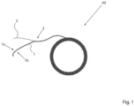
- Fig. 1 is a plan view illustrating the concepts of adhesive, adhesive tape and reel of adhesive tape according to the preset invention.
- Fig. 1 shows the reel 40 of adhesive tape 2.
- the reel 40 comprises an adhesive 1 which on one surface has been provided with a protective liner 3 and which has been wound into a reel. Upon unwinding the tape 2, the tape will comprise an exposed adhesive surface 1b of the adhesive 1. An opposite surface 1a of the adhesive 1 is covered with the protective liner 3.
- adhesive tapes which can be used with the present invention are of the type: foamed acrylic adhesive. Such tapes are marketed under the name of: VHB tape from 3M°, Tesa 4965, Nitto 5703LE or A7040CR from the Crown Adhesive company.
- Fig. 2 is a plan view illustrating one embodiment of the device according to the invention in one of its most simple embodiments.
- the device is for applying an adhesive to a longitudinal product.
- Fig. 2 shows the device 100 comprising a body 6 which comprises a guide member 8.
- the guide member 8 comprises a channel 10 in the form of a through-going channel for receiving and guiding a longitudinal product through said guide member.
- the through-going channel 10 is having a first end 12 and a second end 14.
- the second end 14 of the through-going channel 10 faces in Fig. 2 the viewer and the first end 12 is arranged opposite to the second end 14.
- the through-going channel 10 is for receiving and guiding a longitudinal product through the guide member 8.
- the though-going channel 10 comprises an inner guide surface 18. It is also seen that a tape slot 16 extends into the inner guide surface 18 of the through-going channel 10. Thereby it is possible to feed an adhesive tape 2, via the tape slot 16, into the through-going channel 10 of the guide member 8.
- an end of the adhesive tape 2 is introduced into the tape slot 16 and it is pushed further into the though-going channel 10 of the guide member 8 in such an orientation that the exposed adhesive 1,1b of the adhesive tape 2 faces the first end 12 of the through-going channel 10.
- the exposed adhesive 1 of the adhesive tape 2 will adhere to the longitudinal product 4. This is brought about by help of the inner guide surface 18 of the through-going channel 10 in that this inner guide surface 18 aids in pressing the exposed adhesive 1 of the adhesive tape 2 against the longitudinal product.
- the adhesive tape 2 is cut and the longitudinal product can be removed from the device 100.
- the longitudinal product will be applied with an adhesive, where one surface 1b of the adhesive 1 adheres to the longitudinal product 4 and the opposite surface 1a of the adhesive 1 is protected by a protective liner 3.
- the protective liner 3 is simply removed, thereby exposing the adhesive surface 1a of the adhesive 1, and by pressing this exposed adhesive against a surface, the longitudinal product 4 will be adhered to that surface.
- Fig. 2 shows that the through-going channel 10 is having an essentially linear extension through the guide member 8.
- Fig. 2 also shows that the tape slot 16 extends into the through-going channel 10 in a direction essentially perpendicular to the linear extension of the through-going channel 10.
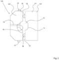
- Fig. 3 is a plan view illustrating the embodiment of Fig. 2 in a disassembled state. Accordingly, Fig. 3 shows that the guide member 8 of device 100 comprising the body 6 can be taken apart in two separate guide member parts, viz. a first guide member part 24 and a second guide member part 26.
- Fig. 3 illustrates that the first guide member part 24 comprises a first guide member engagement means 28. These first guide member engagement means 28 are configured to enter into engagement with a second guide member engagement means 30 in the form of corresponding holes arranged in the second guide member part 26 (not seen in fig. 3 ).
- Fig. 2 and 3 show that the guide member 8 is being divided into the first guide member part 24 and said second guide member part 26 at an interphase 33, the interphase is being arranged along the channel 10.
- Fig. 4a is a plan view illustrating the first guide member part 24 and the second guide member part 26 of the guide member 8 in a disassembled state. Again, it is seen that the guide member 8 comprising the two guide member parts 24 and 26 comprises a channel 10 having a first end 12 and a second end 14.
- the two guide member parts 24 and 26 are configured to be assembled into an assembled guide member 8 by making the interface surface 33 of the two guide member parts 24 and 26 face each other.
- the protrusions of the first guide member engagement means 28 will engage with the holes 30 of the second guide member engagement means 30, thereby holding the first guide member part 24 and the second guide member part 26 of the guide member 8 into a fixed position in relation to each other.
- Fig. 4a also shows the second guide member attachment means 22,22b of the second guide member part 26. These means 22,22b are configured to engage with body attachment means 20 of the body 6 of the device 100.
- the first guide member attachment means 22,22a of the first guide member part 24 simply comprises the shape of the sides of the second guide member part 24 which will enter into engagement with the body 6 of the device 100 and will be hold in place solely by friction.
- Fig. 4b is a cross-sectional view illustrating the first guide member part and the second guide member part of an alternative embodiment of the first aspect of the invention.
- Fig. 4b shows the first guide member part 24 and the second guide member part 26 of a guide member 8, which are shaped so as form the channel 10 for a longitudinal product along a surface of each of the two guide member parts 24,26.
- Fig. 5 is a cross-sectional view illustrating another embodiment of the device of the invention.
- Fig 5 shows the device 100 comprising the body 6.
- the device 100 in fig. 5 comprises the guide member area 9 for accommodating the detachable guide member 8 illustrated in Fig. 2 , 3 and 4 .
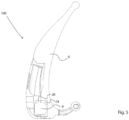
- Fig. 6 is a perspective view illustrating yet another embodiment of the device of the invention.
- the embodiment shown in Fig. 6 corresponds to the embodiment of Fig. 5 .
- the device 100 has been provided with a tape reel holder 38 for holding a reel 40 of adhesive tape 2.
- the tape reel holder comprises a post 44 having a proximal portion 46 and a distal portion 48, wherein the proximal portion is being attached to the body 6 of the device. It is seen that the distal portion 48 comprises reel holding means 50.
- the reel holding means is configured to allow a tape reel, once being mounted on the tape reel holder 38, to rotate relative to the post 44.
- the tape reel holder 38 is having an orientation relative to the tape slot 16 of the guide member 8 in a way enabling that once being loaded with a reel 40 of tape 2, the reel 40 of tape defines a plane which essentially intersects the tape slot 16.
- the adhesive tape 2 can be guided without excessive bends into the tape slot 16.
- the body 6 of the device illustrated in Fig. 6 comprises a first body member 32 and a second body member 34.
- the first body member 32 and the second body member 34 are pivotally mounted to each other around a pivoting point 36.
- the device 100 can attain an open configuration and a closed configuration.
- Fig. 7 is a perspective view illustrating the embodiment of Fig. 6 as seen from another perspective and without the guide member 8.
- Fig. 7 shows that the first body member 32 and a second body member 34 been pivotally rotated slightly in relation to each other around pivoting point 36. Hereby the first body member 32 and the second body member 34 are brought into an open configuration in relation to each other.
- first body member 32 and the second body member 34 each comprises a guide member area 9 for accommodating a first guide member part 24 and a second guide member part 26, respectively.
- the shape of the lower guide member area 9 defines the first body attachment means 20,20a for holding the first guide member part 26 into place solely via friction.
- the upper guide member area 9 comprises the second body attachment means 20,20b for holding the second guide member part 26 into place.
- This embodiment is advantageous because it allows a longitudinal product to be applied with an adhesive even though that product is having an end which is too big to enter the first or second end 12,14 of the channel 10 of the guide member 8.
- the longitudinal product is arranged along the longitudinal channel 10 between the first guide member part 24 and the second guide member part 26 in their open configuration. Subsequently these two guide member parts 24,26 will be brought together in their closed configuration and the application of the adhesive 1 can commence by displacing the longitudinal product 4.
- Fig. 8 is a perspective view of the embodiment illustrated in Fig. 7 .
- the first guide member part 24 and the second guide member part 26 have been inserted into the respective guide member area 9 of the first body member 32 and the second body member 34, respectively.
- Fig. 9 is a photograph illustrating the use of the device according to the first aspect in the process of applying an adhesive to a longitudinal product.
- Fig. 9 shows the device 100 comprising a first body member 32, a second body member 34 and a tape reel holder 38 comprising a post 44 and reel holding means 50 for holding a reel 40 of adhesive tape 2.
- the device also comprises a guide member 8 comprising guide member parts 24, 26 (barely seen in Fig. 9 between the front of first body member 32 and second body member 34).
- Fig. 9 it is seen that the adhesive tape 2 has been pulled off the reel 40 and guided into the tape slot 16 of the guide member 8. Hereby an adhesive surface 1b of the adhesive tape 2 will be exposed.
- the adhesive surface 1b of the adhesive tape 2 faces, in the tape slot 16, the first end 12 of the channel 10 of the guide member 8.
- the longitudinal member 4 in the form of an electric cable has been inserted into the first end 12 of the guide member 8 and the cable 4 has been displaced through the channel 10 in a direction from the first end 12 to the second end 14.
- the adhesive tape 2 is cut and the cable 4 with the adhesive 1 covered by the protective liner 3 can be removed from the device 100.
- Fig. 10 is a photograph illustrating the device 100 according to the first aspect of the present invention.
- Fig. 10 shows that the device 100 has been provided with a roller 56.
- the roller 56 comprises first attachment means 52 which are configured to be clipped onto second attachment means 54 provided on the body 6 of the device 100.
- the first attachment means 52 are also seen in Fig. 13 and the second attachment means 54 are seen Fig. 8 , 9 , 10 and 13 .
- Providing the device 100 with a roller enables application of pressure to the adhesive of the longitudinal product upon fastening that product to a surface.
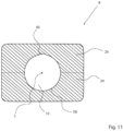
- Fig. 11 is a cross-sectional view of an embodiment of the guide member of the device according to the present invention.
- Fig. 11 shows that the cross-section of the channel 10 of the guide member 8 comprises an essential circular curve 58 comprising a notch 60.
- the notch 60 extends away from the center C of the circular curve and into the material of the guide member.
- the notch 60 extends all the way along the channel 10 of the guide member 8 in a linear extension.
- the notch 60 is arranged at that longitudinal part of the surface of the channel 10 corresponding to the location of the tape slot 16.
- the longitudinal notch 60 will help guiding the location of application of an adhesive tape 2 upon using the device according to the invention on a cylindrical product 4 having a circular cross-section.
- Fig. 12 is a cross-sectional view illustrating the principle of a special embodiment of the guide member of the device according to the invention.
- Fig. 12 shows the guide member 8 comprising a channel 10 and a tape slot 16 extending through the material of the guide member 8 into the channel 10.
- a longitudinal product 4 has been inserted with the view to apply this product with an adhesive tape 2 originating from the reel 40.
- Fig. 12 also shows that an auxiliary tape slot 62 has been provided in the guide member 8.
- the auxiliary tape slot 62 extends into the channel 10 through the material of the guide member 8 at a position next to the tape slot 16.
- a protective tape 64 can be applied on top of the adhesive tape 2 which has been applied to the longitudinal product 4.
- This embodiment is advantageous in case it is desired to provide a longitudinal member 4 with an adhesive tape, but which is intended for being stored for prolonged periods of time until use.
- Fig. 13 is a photograph illustrating the device 100 according to the first aspect of the present invention in a disassembled state.
- the various parts making up the device of the present invention may suitably be manufactured from plastic or metal, such as by molding or by 3D printing.
- Fig. 14 is a perspective view illustrating an embodiment of the device according to the first aspect of the present invention comprising an auxiliary tape slot for a protective tape in addition to a tape slot for the adhesive tape to be applied to a longitudinal product.
- Fig. 14 accordingly shows the device 100 comprising a first guide member part 24 which is pivotally connected to the body 6 which integrated therewith comprises the second guide member part 26.
- the guide member 6 comprising the first guide member part 24 and the second guide member part 26 comprises a tape slot 16 for an adhesive tape as well as auxiliary tape slot 62 for a protective tape to be applied on top of the adhesive tape onto a longitudinal product.
- the tape reel holders 38 comprise reel holding means 50.
Landscapes
- Engineering & Computer Science (AREA)
- Architecture (AREA)
- Civil Engineering (AREA)
- Structural Engineering (AREA)
- Manufacturing & Machinery (AREA)
- Coating Apparatus (AREA)
- Adhesive Tape Dispensing Devices (AREA)
- Adhesive Tapes (AREA)
- Adhesives Or Adhesive Processes (AREA)
- Folding Of Thin Sheet-Like Materials, Special Discharging Devices, And Others (AREA)
Claims (15)
- Vorrichtung (100) zum Auftragen eines Klebstoffs (1) auf ein längliches Produkt (4), wobei die Vorrichtung Folgendes umfasst:einen Körper (6), der ein Führungselement (8) umfasst; wobei das Führungselement (8) einen Kanal (10) zum Aufnehmen und Führen eines länglichen Produkts in Bezug auf das Führungselement umfasst, wobei der Kanal (10) ein erstes Ende (12) und ein zweites Ende (14) aufweist;wobei das Führungselement (8) einen Bandschlitz (16) zum Führen eines Klebebandes (2) in den Kanal (10) umfasst;wobei der Kanal (10) eine Führungsoberfläche (18) umfasst; und wobei sich der Bandschlitz (16) durch mindestens einen Teil des Materials des Führungselements (8) und in die Führungsoberfläche (18) des Kanals (10) erstreckt, wodurch ein Zuführen eines Klebebandes (2) durch das Material des Führungselements (8) und in den Kanal (10) des Führungselements (8) ermöglicht wird, wobei das Führungselement (8) einen ersten Führungselementteil (24) und einen zweiten Führungselementteil (26) umfasst;dadurch gekennzeichnet, dassdas Führungselement (8) in das erste Führungselementteil (24) und das zweite Führungselementteil (26) unterteilt ist, die getrennt sind und an einer Zwischenphase (33) auseinandergenommen werden können, wobei die Zwischenphase entlang des Kanals (10) angeordnet ist, wodurch sie den Kanal (10) entlang einer Längsrichtung davon schneidet.
- Vorrichtung (100) nach Anspruch 1, wobei der Kanal (10) des Führungselements (8) eine im Wesentlichen lineare Erstreckung aufweist; und/oderwobei der Kanal (10) des Führungselements (8) ein durchgehender Kanal ist, der sich durch das Material des Führungselements erstreckt; oder ein Kanal (10) in einer Form einer Vertiefung ist, die an einer Oberfläche des Führungselements angeordnet ist; und/oderwobei der Kanal (10) eine Querschnittsgeometrie aufweist, die aus der Gruppe der folgenden Geometrien ausgewählt ist: ein Kreis, ein Oval, ein Dreieck, ein Rechteck, wie etwa ein Quadrat, oder ein Sechseck.
- Vorrichtung (100) nach einem der Ansprüche 1 - 2, wobei das Führungselement (8) in den Körper (6) der Vorrichtung integriert ist; oder
wobei das Führungselement (8) dazu konfiguriert ist, lösbar an dem Körper (6) der Vorrichtung montiert zu sein; wobei optional der Körper (6) der Vorrichtung ein Körperbefestigungsmittel (20) umfasst und wobei das Führungselement (8) Führungselementbefestigungsmittel (22) umfasst; wobei das Körperbefestigungsmittel (20) und die Führungselementbefestigungsmittel (22) so ausgelegt sind, dass sie in der Lage sind, lösbar miteinander in Eingriff zu treten, wodurch ein Austausch des Führungselements (8) an dem Körper (6) ermöglicht wird. - Vorrichtung (100) nach einem der vorhergehenden Ansprüche, wobei der erste Führungselementteil (24) ein erstes Führungselementeingriffsmittel (28) umfasst und wobei der zweite Führungselementteil (26) ein zweites Führungselementeingriffsmittel (30) umfasst; wobei das erste Führungselementeingriffsmittel (28) und das zweite Führungselementeingriffsmittel (30) dazu konfiguriert sind, lösbar in Eingriff miteinander zu treten.
- Vorrichtung (100) nach einem der vorhergehenden Ansprüche, wobei der Körper (6) ein erstes Körperelement (32) und ein zweites Körperelement (34) umfasst; wobei das erste Körperelement (32) und das zweite Körperelement (34) auf eine schwenkbare Art um einen Schwenkpunkt (36) aneinander befestigt sind, wodurch zwei Backen gebildet werden, die dazu konfiguriert sind, durch Drehung relativ zueinander eine Änderung der Konfiguration der Vorrichtung zwischen einer offenen Konfiguration und einer geschlossenen Konfiguration möglich zu machen;wobei optional das erste Körperelement (32) ein erstes Körperbefestigungsmittel (20a) umfasst; und wobei das zweite Körperelement (34) ein zweites Körperbefestigungsmittel (20b) umfasst; wobei der erste Führungselementteil (24) ein erstes Führungselementbefestigungsmittel (22a) umfasst, wobei der zweite Führungselementteil (26) ein zweites Führungselementbefestigungsmittel (22b) umfasst; wobei das erste Körperbefestigungsmittel (20a) dazu konfiguriert ist, lösbar mit dem ersten Führungselementbefestigungsmittel (22a) in Eingriff zu treten; und wobei das zweite Körperbefestigungsmittel (20b) dazu konfiguriert ist, lösbar mit dem zweiten Führungselementbefestigungsmittel (22b) in Eingriff zu treten, wobei der Kanal (10) dadurch bei Bringen der Vorrichtung in ihre geschlossene Konfiguration gebildet wird;oder wobei optional das erste Körperelement (32) ein erstes Körperbefestigungsmittel (20a) umfasst, wobei das erste Führungselementteil (24) ein erstes Führungselementbefestigungsmittel (22a) umfasst; wobei das erste Körperbefestigungsmittel (20a) dazu konfiguriert ist, lösbar mit dem ersten Führungselementbefestigungsmittel (22a) in Eingriff zu treten; und wobei das zweite Führungselementteil (26) in das zweite Körperelement (34) integriert ist.
- Vorrichtung (100) nach einem der vorhergehenden Ansprüche, wobei der Bandschlitz (16) ein geschlossener Bandschlitz ist, der Zugang zu dem Kanal (10) nur von einer Endöffnung des Bandschlitzes aus ermöglicht, die gegenüber dem Eingang des Bandschlitzes (16) in den Kanal (10) in dem Führungselement (8) angeordnet ist; oder wobei der Bandschlitz (16) ein offener Bandschlitz ist, der ferner Zugang zu dem Kanal (10) entlang der Erstreckung des Bandschlitzes (16) ermöglicht.
- Vorrichtung (100) nach einem der vorhergehenden Ansprüche, wobei der Querschnitt des Kanals (10) des Führungselements (8) eine im Wesentlichen kreisförmige Kurve (58) umfasst, die eine Kerbe (60) umfasst, wobei die Kerbe sich von der Mitte (C) der kreisförmigen Kurve weg und in das Material des Führungselements (8) hinein erstreckt;wobei sich die Kerbe (60) optional über die gesamte Längsrichtung des Kanals (10) erstreckt;und/oder wobei optional die Kerbe (60) an dem länglichen Teil der Oberfläche des Kanals (10) angeordnet ist, der der Stelle des Eingangs des Bandschlitzes (16) entspricht.
- Vorrichtung (100) nach Anspruch 5, wobei das erste Körperelement (32) und/oder das zweite Körperelement (34) eine längliche Aussparung umfasst, wodurch das Führungselement (8) als integraler Teil des Körpers (6) gebildet wird; wobei die Aussparung(en) dadurch den Kanal (10) definiert/definieren, wenn das erste Körperelement (32) und das zweite Körperelement (34) in ihre geschlossene Konfiguration gebracht sind;
wobei optional das erste Körperelement (32) und das zweite Körperelement (34) Eingriffsmittel (28,30) umfassen, die dazu konfiguriert sind, in Eingriff miteinander zu treten, wenn das erste Körperelement (32) und das zweite Körperelement (34) in ihre geschlossene Konfiguration gebracht sind, wodurch jegliche seitliche Bewegung des ersten Körperelements (32) und des zweiten Körperelements (34) relativ zueinander verhindert wird, wenn sie sich in ihrer geschlossenen Konfiguration befinden. - Vorrichtung (100) nach einem der vorhergehenden Ansprüche, wobei die Vorrichtung ferner noch einen Bandrollenhalter (38) zum Halten einer Rolle (40) Klebeband (2) umfasst;wobei der Bandrollenhalter (38) optional eine Ausrichtung relativ zu dem Bandschlitz (16) des Führungselements (8) derart aufweist, dass es möglich gemacht wird, dass, nachdem er mit einer Rolle Klebeband (2) bestückt wurde, die Rolle (40) Klebeband eine Ebene definiert, die den Bandschlitz (16) im Wesentlichen schneidet; und/oderwobei der Bandrollenhalter (38) optional einen Ständer (44) umfasst, der einen proximalen Abschnitt (46) und einen distalen Abschnitt (48) aufweist, wobei der proximale Abschnitt an dem Körper (6) der Vorrichtung befestigt ist und wobei der distale Abschnitt ein Rollenhaltemittel (50) umfasst, wobei das Rollenhaltemittel dazu konfiguriert sind, es einer Bandrolle (40) zu ermöglichen, sobald sie an dem Bandrollenhalter (38) montiert ist, sich relativ zu dem Ständer zu drehen;
oderwobei die Vorrichtung ferner eine Walze (56) umfasst, wobei die Walze erste Walzenbefestigungsmittel (52) umfasst, und wobei der Körper (6) zweite Walzenbefestigungsmittel (54) umfasst, wobei die ersten Walzenbefestigungsmittel (52) dazu konfiguriert sind, lösbar mit den zweiten Walzenbefestigungsmitteln (54) in Eingriff zu treten. - Vorrichtung (100) nach einem der vorhergehenden Ansprüche, wobei das Führungselement (8) einen zusätzlichen Bandschlitz (62) zum Führen eines Schutzbandes (64) in den Kanal (10) umfasst, wobei sich der zusätzliche Bandschlitz (62) durch das Material des Führungselements (8) in den Kanal (10) an einer Stelle neben dem Bandschlitz (16) erstreckt; optional ferner einen Bandrollenhalter für das Schutzband (64) umfassend.
- System (200), umfassend eine Vorrichtung (100) nach einem der Ansprüche 1 - 10 in Kombination mit einem Satz von zwei oder mehreren Führungselementen (8), wobei die Geometrien und/oder Abmessungen des Kanals (10) in Bezug auf zwei oder mehrere der zwei oder mehreren Führungselemente unterschiedlich sind.
- Teilesatz (300), umfassend eine Vorrichtung (100) nach einem der Ansprüche 1 - 10 in Kombination mit einer oder mehreren Rollen (40) Klebeband (2); und wobei die Geometrie und die Abmessungen des Klebebandes (2) an die Geometrie und die Abmessungen des Bandschlitzes (16) eines Führungselements (8) der Vorrichtung angepasst sind; optional ferner in Kombination mit einer oder mehreren Rollen Schutzband (64).
- Verwendung einer Vorrichtung (100) nach einem der Ansprüche 1 - 10; oder eines Systems (200) nach Anspruch 11 oder eines Teilesatzes (300) nach Anspruch 12 zum Auftragen eines Klebstoffs (1) auf ein längliches Produkt (4).
- Verfahren zum Auftragen eines Klebstoffs (1) auf ein längliches Produkt (4), wobei das Verfahren die folgenden Schritte umfasst:i) Bereitstellen einer Vorrichtung (100) nach einem der Ansprüche 1 - 10;ii) Einführen eines Endes des Klebebandes (2) über den Bandschlitz (16) in den Kanal (10) des Führungselements (8) der Vorrichtung derart, dass der freiliegende Klebstoff (1) des Klebebandes (2) beim Eintreten in den Kanal (10) dem ersten Ende (12) des Kanals (10) zugewandt ist;iii) Anordnen des länglichen Produkts (4) in dem Kanal (10) des Führungselements (8);iv) Verschieben des länglichen Produkts (4) entlang des Kanals (10) des Führungselements (8) in einer Richtung von dem ersten Ende (12) des Kanals zu dem zweiten Ende (14) des Kanals, wodurch bewirkt wird, dass der freiliegende Klebstoff (1) des Klebebandes (2) entlang einer gewünschten Erstreckung davon an dem länglichen Produkt (4) haftet;v) Durchschneiden des Klebebandes (2), sobald die gewünschte Erstreckung des Auftragens erreicht ist.
- Verfahren nach Anspruch 14, wobei das längliche Produkt (4) ein flexibles Produkt ist, wie etwa ein Elektrokabel, ein Datenkabel, eine Gummidichtung; ein Rohr oder Schlauch, wie etwa ein flexibles Rohr oder Schlauch, wie etwa ein flexibles Rohr zur Versorgung eines Patienten mit Luft oder Sauerstoff in medizinischer Qualität; oder wobei das längliche Produkt (4) ein nicht flexibles Produkt ist, wie etwa ein extrudiertes Aluminiumprofil, eine Leiste für Fenster oder für Bodenpaneele.
Applications Claiming Priority (2)
| Application Number | Priority Date | Filing Date | Title |
|---|---|---|---|
| DKPA202001440A DK181134B1 (en) | 2020-12-21 | 2020-12-21 | Device, system and method for applying an adhesive to a longitudinal product |
| PCT/DK2021/050376 WO2022135642A2 (en) | 2020-12-21 | 2021-12-20 | A device for applying an adhesive to a longitudinal product |
Publications (3)
| Publication Number | Publication Date |
|---|---|
| EP4263173A2 EP4263173A2 (de) | 2023-10-25 |
| EP4263173C0 EP4263173C0 (de) | 2025-01-29 |
| EP4263173B1 true EP4263173B1 (de) | 2025-01-29 |
Family
ID=79270276
Family Applications (1)
| Application Number | Title | Priority Date | Filing Date |
|---|---|---|---|
| EP21838979.9A Active EP4263173B1 (de) | 2020-12-21 | 2021-12-20 | Vorrichtung zum auftragen eines klebstoffes auf ein längliches produkt |
Country Status (6)
| Country | Link |
|---|---|
| US (1) | US20240067487A1 (de) |
| EP (1) | EP4263173B1 (de) |
| AU (1) | AU2021406449A1 (de) |
| CA (1) | CA3200647A1 (de) |
| DK (1) | DK181134B1 (de) |
| WO (1) | WO2022135642A2 (de) |
Citations (1)
| Publication number | Priority date | Publication date | Assignee | Title |
|---|---|---|---|---|
| US20120318445A1 (en) * | 2010-02-25 | 2012-12-20 | Kozo Odawara | Tape applying device, tape holding unit, and tape applying method |
Family Cites Families (3)
| Publication number | Priority date | Publication date | Assignee | Title |
|---|---|---|---|---|
| GB2483950A (en) * | 2011-04-26 | 2012-03-28 | Howe Renovation Yorks Ltd | Cable laying device dispensing adhesive |
| KR20170047191A (ko) * | 2014-01-28 | 2017-05-04 | 개프테크, 엘엘씨 | 테이프 어플리케이터 어셈블리 및 테이프 어셈블리 |
| CN110556743B (zh) * | 2019-08-22 | 2020-11-13 | 莆田市城厢区宸意美贸易有限公司 | 一种电线铺胶带涂抹器 |
-
2020
- 2020-12-21 DK DKPA202001440A patent/DK181134B1/en active IP Right Grant
-
2021
- 2021-12-20 EP EP21838979.9A patent/EP4263173B1/de active Active
- 2021-12-20 AU AU2021406449A patent/AU2021406449A1/en active Pending
- 2021-12-20 US US18/268,446 patent/US20240067487A1/en active Pending
- 2021-12-20 WO PCT/DK2021/050376 patent/WO2022135642A2/en not_active Ceased
- 2021-12-20 CA CA3200647A patent/CA3200647A1/en active Pending
Patent Citations (1)
| Publication number | Priority date | Publication date | Assignee | Title |
|---|---|---|---|---|
| US20120318445A1 (en) * | 2010-02-25 | 2012-12-20 | Kozo Odawara | Tape applying device, tape holding unit, and tape applying method |
Also Published As
| Publication number | Publication date |
|---|---|
| WO2022135642A3 (en) | 2022-09-01 |
| EP4263173C0 (de) | 2025-01-29 |
| CA3200647A1 (en) | 2022-06-30 |
| DK181134B1 (en) | 2023-02-13 |
| AU2021406449A1 (en) | 2023-06-22 |
| WO2022135642A2 (en) | 2022-06-30 |
| DK202001440A1 (en) | 2022-06-22 |
| US20240067487A1 (en) | 2024-02-29 |
| EP4263173A2 (de) | 2023-10-25 |
Similar Documents
| Publication | Publication Date | Title |
|---|---|---|
| US6838615B2 (en) | Glide assembly for conduit bodies | |
| EP2811596B1 (de) | Anschlussbox für Glasfaserkabel und Verfahren zur Installation eines Glasfaserkabels | |
| US7000746B2 (en) | Electric cord reel | |
| JP6954197B2 (ja) | 組付補助部品付配線体、配線体の組付補助部品及び配線体組付物の製造方法 | |
| CA2643316C (en) | Large capacity universal conduit bodies | |
| US8374475B2 (en) | Optical waveguide assembly, storage device, and method for installing an optical waveguide | |
| EP4263173B1 (de) | Vorrichtung zum auftragen eines klebstoffes auf ein längliches produkt | |
| US11105999B2 (en) | Telecommunications cabling system | |
| US9122034B2 (en) | Cable slack storage for wall outlet | |
| US11522351B2 (en) | Wire management system and kit | |
| US6991220B2 (en) | Raceway line puller and method of using same | |
| JPH0659137A (ja) | 光ファイバの布設方法、布設工具及び光ファイバ配線 | |
| WO2018119141A1 (en) | Cable conduit | |
| JP3013279B2 (ja) | ケーブル収容布設具及びケーブル布設方法 | |
| WO2006095147A1 (en) | Apparatus for optical fibre installation by fluid drag | |
| EP4648239A1 (de) | Abgewinkelte ankerhalterungen | |
| US20250350103A1 (en) | Transition Fixing | |
| JP2904484B1 (ja) | 通信機器用装置架のケーブル導入構造 | |
| JP6713077B1 (ja) | 延線用治具、電線・ケーブル及び電線・ケーブルの延線方法 | |
| US20070223768A1 (en) | Spring tension mounting mechanism for speakers and electronic modules | |
| JP2002328242A (ja) | 光ファイバケーブル接続用クロージャ | |
| JP2000089074A (ja) | 光クロージャの収納構造 | |
| JPH09149519A (ja) | ケーブル布設用リード治具 | |
| JP2008112008A (ja) | 光ケーブル機器筐体の光ケーブル固定構造 | |
| TH27822B (th) | อุปกรณ์เดินสายสำหรับเส้นใยนำแสง |
Legal Events
| Date | Code | Title | Description |
|---|---|---|---|
| STAA | Information on the status of an ep patent application or granted ep patent |
Free format text: STATUS: UNKNOWN |
|
| STAA | Information on the status of an ep patent application or granted ep patent |
Free format text: STATUS: THE INTERNATIONAL PUBLICATION HAS BEEN MADE |
|
| PUAI | Public reference made under article 153(3) epc to a published international application that has entered the european phase |
Free format text: ORIGINAL CODE: 0009012 |
|
| STAA | Information on the status of an ep patent application or granted ep patent |
Free format text: STATUS: REQUEST FOR EXAMINATION WAS MADE |
|
| 17P | Request for examination filed |
Effective date: 20230524 |
|
| AK | Designated contracting states |
Kind code of ref document: A2 Designated state(s): AL AT BE BG CH CY CZ DE DK EE ES FI FR GB GR HR HU IE IS IT LI LT LU LV MC MK MT NL NO PL PT RO RS SE SI SK SM TR |
|
| DAV | Request for validation of the european patent (deleted) | ||
| DAX | Request for extension of the european patent (deleted) | ||
| GRAP | Despatch of communication of intention to grant a patent |
Free format text: ORIGINAL CODE: EPIDOSNIGR1 |
|
| STAA | Information on the status of an ep patent application or granted ep patent |
Free format text: STATUS: GRANT OF PATENT IS INTENDED |
|
| INTG | Intention to grant announced |
Effective date: 20241008 |
|
| GRAS | Grant fee paid |
Free format text: ORIGINAL CODE: EPIDOSNIGR3 |
|
| GRAA | (expected) grant |
Free format text: ORIGINAL CODE: 0009210 |
|
| STAA | Information on the status of an ep patent application or granted ep patent |
Free format text: STATUS: THE PATENT HAS BEEN GRANTED |
|
| AK | Designated contracting states |
Kind code of ref document: B1 Designated state(s): AL AT BE BG CH CY CZ DE DK EE ES FI FR GB GR HR HU IE IS IT LI LT LU LV MC MK MT NL NO PL PT RO RS SE SI SK SM TR |
|
| REG | Reference to a national code |
Ref country code: GB Ref legal event code: FG4D |
|
| REG | Reference to a national code |
Ref country code: CH Ref legal event code: EP |
|
| REG | Reference to a national code |
Ref country code: DE Ref legal event code: R096 Ref document number: 602021025604 Country of ref document: DE |
|
| REG | Reference to a national code |
Ref country code: IE Ref legal event code: FG4D |
|
| U01 | Request for unitary effect filed |
Effective date: 20250219 |
|
| U07 | Unitary effect registered |
Designated state(s): AT BE BG DE DK EE FI FR IT LT LU LV MT NL PT RO SE SI Effective date: 20250225 |
|
| PG25 | Lapsed in a contracting state [announced via postgrant information from national office to epo] |
Ref country code: RS Free format text: LAPSE BECAUSE OF FAILURE TO SUBMIT A TRANSLATION OF THE DESCRIPTION OR TO PAY THE FEE WITHIN THE PRESCRIBED TIME-LIMIT Effective date: 20250429 |
|
| PG25 | Lapsed in a contracting state [announced via postgrant information from national office to epo] |
Ref country code: PL Free format text: LAPSE BECAUSE OF FAILURE TO SUBMIT A TRANSLATION OF THE DESCRIPTION OR TO PAY THE FEE WITHIN THE PRESCRIBED TIME-LIMIT Effective date: 20250129 |
|
| PG25 | Lapsed in a contracting state [announced via postgrant information from national office to epo] |
Ref country code: ES Free format text: LAPSE BECAUSE OF FAILURE TO SUBMIT A TRANSLATION OF THE DESCRIPTION OR TO PAY THE FEE WITHIN THE PRESCRIBED TIME-LIMIT Effective date: 20250129 |
|
| PG25 | Lapsed in a contracting state [announced via postgrant information from national office to epo] |
Ref country code: IS Free format text: LAPSE BECAUSE OF FAILURE TO SUBMIT A TRANSLATION OF THE DESCRIPTION OR TO PAY THE FEE WITHIN THE PRESCRIBED TIME-LIMIT Effective date: 20250529 Ref country code: NO Free format text: LAPSE BECAUSE OF FAILURE TO SUBMIT A TRANSLATION OF THE DESCRIPTION OR TO PAY THE FEE WITHIN THE PRESCRIBED TIME-LIMIT Effective date: 20250429 |
|
| PG25 | Lapsed in a contracting state [announced via postgrant information from national office to epo] |
Ref country code: HR Free format text: LAPSE BECAUSE OF FAILURE TO SUBMIT A TRANSLATION OF THE DESCRIPTION OR TO PAY THE FEE WITHIN THE PRESCRIBED TIME-LIMIT Effective date: 20250129 |
|
| PG25 | Lapsed in a contracting state [announced via postgrant information from national office to epo] |
Ref country code: GR Free format text: LAPSE BECAUSE OF FAILURE TO SUBMIT A TRANSLATION OF THE DESCRIPTION OR TO PAY THE FEE WITHIN THE PRESCRIBED TIME-LIMIT Effective date: 20250430 |
|
| PG25 | Lapsed in a contracting state [announced via postgrant information from national office to epo] |
Ref country code: SM Free format text: LAPSE BECAUSE OF FAILURE TO SUBMIT A TRANSLATION OF THE DESCRIPTION OR TO PAY THE FEE WITHIN THE PRESCRIBED TIME-LIMIT Effective date: 20250129 |
|
| PG25 | Lapsed in a contracting state [announced via postgrant information from national office to epo] |
Ref country code: CZ Free format text: LAPSE BECAUSE OF FAILURE TO SUBMIT A TRANSLATION OF THE DESCRIPTION OR TO PAY THE FEE WITHIN THE PRESCRIBED TIME-LIMIT Effective date: 20250129 |
|
| PG25 | Lapsed in a contracting state [announced via postgrant information from national office to epo] |
Ref country code: SK Free format text: LAPSE BECAUSE OF FAILURE TO SUBMIT A TRANSLATION OF THE DESCRIPTION OR TO PAY THE FEE WITHIN THE PRESCRIBED TIME-LIMIT Effective date: 20250129 |
|
| PLBE | No opposition filed within time limit |
Free format text: ORIGINAL CODE: 0009261 |
|
| STAA | Information on the status of an ep patent application or granted ep patent |
Free format text: STATUS: NO OPPOSITION FILED WITHIN TIME LIMIT |
|
| U20 | Renewal fee for the european patent with unitary effect paid |
Year of fee payment: 5 Effective date: 20251117 |
|
| 26N | No opposition filed |
Effective date: 20251030 |
|
| PGFP | Annual fee paid to national office [announced via postgrant information from national office to epo] |
Ref country code: GB Payment date: 20251219 Year of fee payment: 5 |