EP4263146B1 - Verfahren zum bewegen eines exoskeletts - Google Patents
Verfahren zum bewegen eines exoskeletts Download PDFInfo
- Publication number
- EP4263146B1 EP4263146B1 EP21851677.1A EP21851677A EP4263146B1 EP 4263146 B1 EP4263146 B1 EP 4263146B1 EP 21851677 A EP21851677 A EP 21851677A EP 4263146 B1 EP4263146 B1 EP 4263146B1
- Authority
- EP
- European Patent Office
- Prior art keywords
- exoskeleton
- trajectory
- cop
- expected
- dcm
- Prior art date
- Legal status (The legal status is an assumption and is not a legal conclusion. Google has not performed a legal analysis and makes no representation as to the accuracy of the status listed.)
- Active
Links
Images
Classifications
-
- A—HUMAN NECESSITIES
- A61—MEDICAL OR VETERINARY SCIENCE; HYGIENE
- A61H—PHYSICAL THERAPY APPARATUS, e.g. DEVICES FOR LOCATING OR STIMULATING REFLEX POINTS IN THE BODY; ARTIFICIAL RESPIRATION; MASSAGE; BATHING DEVICES FOR SPECIAL THERAPEUTIC OR HYGIENIC PURPOSES OR SPECIFIC PARTS OF THE BODY
- A61H1/00—Apparatus for passive exercising; Vibrating apparatus; Chiropractic devices, e.g. body impacting devices, external devices for briefly extending or aligning unbroken bones
- A61H1/02—Stretching or bending or torsioning apparatus for exercising
- A61H1/0237—Stretching or bending or torsioning apparatus for exercising for the lower limbs
- A61H1/0255—Both knee and hip of a patient, e.g. in supine or sitting position, the feet being moved together in a plane substantially parallel to the body-symmetrical plane
- A61H1/0262—Walking movement; Appliances for aiding disabled persons to walk
-
- A—HUMAN NECESSITIES
- A61—MEDICAL OR VETERINARY SCIENCE; HYGIENE
- A61H—PHYSICAL THERAPY APPARATUS, e.g. DEVICES FOR LOCATING OR STIMULATING REFLEX POINTS IN THE BODY; ARTIFICIAL RESPIRATION; MASSAGE; BATHING DEVICES FOR SPECIAL THERAPEUTIC OR HYGIENIC PURPOSES OR SPECIFIC PARTS OF THE BODY
- A61H3/00—Appliances for aiding patients or disabled persons to walk about
-
- B—PERFORMING OPERATIONS; TRANSPORTING
- B25—HAND TOOLS; PORTABLE POWER-DRIVEN TOOLS; MANIPULATORS
- B25J—MANIPULATORS; CHAMBERS PROVIDED WITH MANIPULATION DEVICES
- B25J9/00—Programme-controlled manipulators
- B25J9/0006—Exoskeletons, i.e. resembling a human figure
-
- B—PERFORMING OPERATIONS; TRANSPORTING
- B25—HAND TOOLS; PORTABLE POWER-DRIVEN TOOLS; MANIPULATORS
- B25J—MANIPULATORS; CHAMBERS PROVIDED WITH MANIPULATION DEVICES
- B25J9/00—Programme-controlled manipulators
- B25J9/16—Programme controls
- B25J9/1615—Programme controls characterised by special kind of manipulator, e.g. planar, scara, gantry, cantilever, space, closed chain, passive/active joints and tendon driven manipulators
-
- A—HUMAN NECESSITIES
- A61—MEDICAL OR VETERINARY SCIENCE; HYGIENE
- A61H—PHYSICAL THERAPY APPARATUS, e.g. DEVICES FOR LOCATING OR STIMULATING REFLEX POINTS IN THE BODY; ARTIFICIAL RESPIRATION; MASSAGE; BATHING DEVICES FOR SPECIAL THERAPEUTIC OR HYGIENIC PURPOSES OR SPECIFIC PARTS OF THE BODY
- A61H2201/00—Characteristics of apparatus not provided for in the preceding codes
- A61H2201/01—Constructive details
- A61H2201/0157—Constructive details portable
-
- A—HUMAN NECESSITIES
- A61—MEDICAL OR VETERINARY SCIENCE; HYGIENE
- A61H—PHYSICAL THERAPY APPARATUS, e.g. DEVICES FOR LOCATING OR STIMULATING REFLEX POINTS IN THE BODY; ARTIFICIAL RESPIRATION; MASSAGE; BATHING DEVICES FOR SPECIAL THERAPEUTIC OR HYGIENIC PURPOSES OR SPECIFIC PARTS OF THE BODY
- A61H2201/00—Characteristics of apparatus not provided for in the preceding codes
- A61H2201/01—Constructive details
- A61H2201/0173—Means for preventing injuries
- A61H2201/0176—By stopping operation
-
- A—HUMAN NECESSITIES
- A61—MEDICAL OR VETERINARY SCIENCE; HYGIENE
- A61H—PHYSICAL THERAPY APPARATUS, e.g. DEVICES FOR LOCATING OR STIMULATING REFLEX POINTS IN THE BODY; ARTIFICIAL RESPIRATION; MASSAGE; BATHING DEVICES FOR SPECIAL THERAPEUTIC OR HYGIENIC PURPOSES OR SPECIFIC PARTS OF THE BODY
- A61H2201/00—Characteristics of apparatus not provided for in the preceding codes
- A61H2201/01—Constructive details
- A61H2201/0173—Means for preventing injuries
- A61H2201/018—By limiting the applied torque or force
-
- A—HUMAN NECESSITIES
- A61—MEDICAL OR VETERINARY SCIENCE; HYGIENE
- A61H—PHYSICAL THERAPY APPARATUS, e.g. DEVICES FOR LOCATING OR STIMULATING REFLEX POINTS IN THE BODY; ARTIFICIAL RESPIRATION; MASSAGE; BATHING DEVICES FOR SPECIAL THERAPEUTIC OR HYGIENIC PURPOSES OR SPECIFIC PARTS OF THE BODY
- A61H2201/00—Characteristics of apparatus not provided for in the preceding codes
- A61H2201/12—Driving means
- A61H2201/1207—Driving means with electric or magnetic drive
-
- A—HUMAN NECESSITIES
- A61—MEDICAL OR VETERINARY SCIENCE; HYGIENE
- A61H—PHYSICAL THERAPY APPARATUS, e.g. DEVICES FOR LOCATING OR STIMULATING REFLEX POINTS IN THE BODY; ARTIFICIAL RESPIRATION; MASSAGE; BATHING DEVICES FOR SPECIAL THERAPEUTIC OR HYGIENIC PURPOSES OR SPECIFIC PARTS OF THE BODY
- A61H2201/00—Characteristics of apparatus not provided for in the preceding codes
- A61H2201/12—Driving means
- A61H2201/1238—Driving means with hydraulic or pneumatic drive
- A61H2201/1246—Driving means with hydraulic or pneumatic drive by piston-cylinder systems
-
- A—HUMAN NECESSITIES
- A61—MEDICAL OR VETERINARY SCIENCE; HYGIENE
- A61H—PHYSICAL THERAPY APPARATUS, e.g. DEVICES FOR LOCATING OR STIMULATING REFLEX POINTS IN THE BODY; ARTIFICIAL RESPIRATION; MASSAGE; BATHING DEVICES FOR SPECIAL THERAPEUTIC OR HYGIENIC PURPOSES OR SPECIFIC PARTS OF THE BODY
- A61H2201/00—Characteristics of apparatus not provided for in the preceding codes
- A61H2201/14—Special force transmission means, i.e. between the driving means and the interface with the user
- A61H2201/1409—Hydraulic or pneumatic means
-
- A—HUMAN NECESSITIES
- A61—MEDICAL OR VETERINARY SCIENCE; HYGIENE
- A61H—PHYSICAL THERAPY APPARATUS, e.g. DEVICES FOR LOCATING OR STIMULATING REFLEX POINTS IN THE BODY; ARTIFICIAL RESPIRATION; MASSAGE; BATHING DEVICES FOR SPECIAL THERAPEUTIC OR HYGIENIC PURPOSES OR SPECIFIC PARTS OF THE BODY
- A61H2201/00—Characteristics of apparatus not provided for in the preceding codes
- A61H2201/14—Special force transmission means, i.e. between the driving means and the interface with the user
- A61H2201/1481—Special movement conversion means
- A61H2201/149—Special movement conversion means rotation-linear or vice versa
-
- A—HUMAN NECESSITIES
- A61—MEDICAL OR VETERINARY SCIENCE; HYGIENE
- A61H—PHYSICAL THERAPY APPARATUS, e.g. DEVICES FOR LOCATING OR STIMULATING REFLEX POINTS IN THE BODY; ARTIFICIAL RESPIRATION; MASSAGE; BATHING DEVICES FOR SPECIAL THERAPEUTIC OR HYGIENIC PURPOSES OR SPECIFIC PARTS OF THE BODY
- A61H2201/00—Characteristics of apparatus not provided for in the preceding codes
- A61H2201/16—Physical interface with patient
- A61H2201/1602—Physical interface with patient kind of interface, e.g. head rest, knee support or lumbar support
- A61H2201/164—Feet or leg, e.g. pedal
- A61H2201/1642—Holding means therefor
-
- A—HUMAN NECESSITIES
- A61—MEDICAL OR VETERINARY SCIENCE; HYGIENE
- A61H—PHYSICAL THERAPY APPARATUS, e.g. DEVICES FOR LOCATING OR STIMULATING REFLEX POINTS IN THE BODY; ARTIFICIAL RESPIRATION; MASSAGE; BATHING DEVICES FOR SPECIAL THERAPEUTIC OR HYGIENIC PURPOSES OR SPECIFIC PARTS OF THE BODY
- A61H2201/00—Characteristics of apparatus not provided for in the preceding codes
- A61H2201/50—Control means thereof
- A61H2201/5007—Control means thereof computer controlled
- A61H2201/501—Control means thereof computer controlled connected to external computer devices or networks
- A61H2201/5012—Control means thereof computer controlled connected to external computer devices or networks using the internet
-
- A—HUMAN NECESSITIES
- A61—MEDICAL OR VETERINARY SCIENCE; HYGIENE
- A61H—PHYSICAL THERAPY APPARATUS, e.g. DEVICES FOR LOCATING OR STIMULATING REFLEX POINTS IN THE BODY; ARTIFICIAL RESPIRATION; MASSAGE; BATHING DEVICES FOR SPECIAL THERAPEUTIC OR HYGIENIC PURPOSES OR SPECIFIC PARTS OF THE BODY
- A61H2201/00—Characteristics of apparatus not provided for in the preceding codes
- A61H2201/50—Control means thereof
- A61H2201/5023—Interfaces to the user
- A61H2201/5025—Activation means
- A61H2201/5028—Contact activation, i.e. activated at contact with a surface of the user to be treated
-
- A—HUMAN NECESSITIES
- A61—MEDICAL OR VETERINARY SCIENCE; HYGIENE
- A61H—PHYSICAL THERAPY APPARATUS, e.g. DEVICES FOR LOCATING OR STIMULATING REFLEX POINTS IN THE BODY; ARTIFICIAL RESPIRATION; MASSAGE; BATHING DEVICES FOR SPECIAL THERAPEUTIC OR HYGIENIC PURPOSES OR SPECIFIC PARTS OF THE BODY
- A61H2201/00—Characteristics of apparatus not provided for in the preceding codes
- A61H2201/50—Control means thereof
- A61H2201/5058—Sensors or detectors
- A61H2201/5064—Position sensors
-
- A—HUMAN NECESSITIES
- A61—MEDICAL OR VETERINARY SCIENCE; HYGIENE
- A61H—PHYSICAL THERAPY APPARATUS, e.g. DEVICES FOR LOCATING OR STIMULATING REFLEX POINTS IN THE BODY; ARTIFICIAL RESPIRATION; MASSAGE; BATHING DEVICES FOR SPECIAL THERAPEUTIC OR HYGIENIC PURPOSES OR SPECIFIC PARTS OF THE BODY
- A61H2201/00—Characteristics of apparatus not provided for in the preceding codes
- A61H2201/50—Control means thereof
- A61H2201/5058—Sensors or detectors
- A61H2201/5071—Pressure sensors
-
- A—HUMAN NECESSITIES
- A61—MEDICAL OR VETERINARY SCIENCE; HYGIENE
- A61H—PHYSICAL THERAPY APPARATUS, e.g. DEVICES FOR LOCATING OR STIMULATING REFLEX POINTS IN THE BODY; ARTIFICIAL RESPIRATION; MASSAGE; BATHING DEVICES FOR SPECIAL THERAPEUTIC OR HYGIENIC PURPOSES OR SPECIFIC PARTS OF THE BODY
- A61H2205/00—Devices for specific parts of the body
- A61H2205/10—Leg
- A61H2205/106—Leg for the lower legs
-
- A—HUMAN NECESSITIES
- A61—MEDICAL OR VETERINARY SCIENCE; HYGIENE
- A61H—PHYSICAL THERAPY APPARATUS, e.g. DEVICES FOR LOCATING OR STIMULATING REFLEX POINTS IN THE BODY; ARTIFICIAL RESPIRATION; MASSAGE; BATHING DEVICES FOR SPECIAL THERAPEUTIC OR HYGIENIC PURPOSES OR SPECIFIC PARTS OF THE BODY
- A61H2205/00—Devices for specific parts of the body
- A61H2205/12—Feet
-
- G—PHYSICS
- G05—CONTROLLING; REGULATING
- G05B—CONTROL OR REGULATING SYSTEMS IN GENERAL; FUNCTIONAL ELEMENTS OF SUCH SYSTEMS; MONITORING OR TESTING ARRANGEMENTS FOR SUCH SYSTEMS OR ELEMENTS
- G05B2219/00—Program-control systems
- G05B2219/30—Nc systems
- G05B2219/40—Robotics, robotics mapping to robotics vision
- G05B2219/40305—Exoskeleton, human robot interaction, extenders
Definitions
- the present invention relates to the field of bipedal robots such as humanoid robots and exoskeletons.
- exoskeletons have appeared for people with significant mobility problems such as paraplegics.
- These are external robotic devices that the operator (the human user) "puts on” using a system of attachments that links the movements of the exoskeleton to his own movements.
- Lower limb exoskeletons have several joints, generally at least at the knees and hips, to reproduce the walking movement. Actuators allow these joints to be moved, which in turn move the operator.
- An interface system allows the operator to give orders to the exoskeleton, and a control system transforms these orders into commands for the actuators. Sensors generally complete the device.
- exoskeletons are an advance over wheelchairs, as they allow operators to stand up and walk.
- Exoskeletons are no longer limited by wheels and can theoretically operate in most non-flat environments: unlike legs, wheels do not allow you to overcome significant obstacles such as steps, stairs, obstacles that are too high, etc.
- Known exoskeleton control methods allow for stable and autonomous walking on "regular" ground, i.e. plan (incorrectly we speak of flat ground, but we mean a ground free of irregularities, for example indoors or on a treadmill) and to resist minor external disturbances.
- plan incorrectly we speak of flat ground, but we mean a ground free of irregularities, for example indoors or on a treadmill
- resist minor external disturbances for example, we can cite the documents Towards Restoring Locomotion for Paraplegia: Realizing Dynamically Stable Walking on Exoskeletons, T.
- Gurriet et al. or Feedback Control of an Exoskeleton for Paraplegia: Toward Robustly Stable, Hands-Free Dynamic Walking, O. Harib et al; EP 2 497 610 A1 ; CARON STEPHANE ET AL: "Stair Climbing Stabilization of the HRP-4 Humanoid Robot using Whole-body Admittance Control "; Ll ZHIJUN ET AL: "Physical Human-Robot Interaction of a Robotic Exoskeleton By Admittance Control ".
- the method comprises repeating steps (a) and (b) so as to make the exoskeleton walk through a succession of real elementary trajectories each corresponding to a step.
- step (a) starts from an initial position, step (b) comprising the determination of a final position of the exoskeleton at the end of said real elementary trajectory, said final position being used as the initial position at the next occurrence of step (a).
- Step (b) comprises, at the start of each iteration of the loop, applying to the exoskeleton said force torsor determined at the previous iteration by means of an admittance controller.
- Determining a force torsor to be applied to the exoskeleton to compensate for the deviation between said estimated current state of the exoskeleton and an expected state of the exoskeleton in accordance with said theoretical elementary trajectory comprises implementing a feedback control on at least one parameter defining the state of the exoskeleton.
- the position of the exoskeleton is defined by a vector of the joint positions of the actuated degrees of freedom of the exoskeleton, the state of the exoskeleton being defined by at least one parameter chosen from the positions, velocities and accelerations of the actuated degrees, the positions and velocities of a Center of Mass, CoM, of a divergent component of motion, DCM, the position of a Center of Pressure, CoP, and the position of a Zero Moment Point, ZMP; in particular defined by the positions of the Center of Mass, CoM, of the divergent component of motion DCM and of the Center of Pressure CoP.
- Said feedback control is implemented on the position of the DCM.
- Said stress torso to be applied to the exoskeleton 1 is defined by a position of the CoP.
- the said flexibility model defines a modification of the expected position of the CoP used to determine the effort torsor.
- the exoskeleton has at least one flexible actuated degree of freedom, said flexibility model defining an offset to be applied to a target position and/or speed of said flexible actuated degree of freedom determined following the application of the force torsor.
- Said flexibility model defines at least one parameter of the state of the exoskeleton to be replaced by an average value observed on real stable steps.
- the said flexibility model is predetermined experimentally, from real stable walks and/or simulations.
- the invention relates to an exoskeleton comprising data processing means configured to implement a method according to the first aspect of setting the exoskeleton in motion.
- the invention relates to a system comprising a server and the exoskeleton according to the second aspect, the server comprising data processing means configured to generate said theoretical elementary trajectory and provide it to the exoskeleton in step (a).
- the invention relates to a computer program product comprising code instructions for executing a method according to the first aspect of setting an exoskeleton in motion; and a storage means readable by computer equipment on which a computer program product comprises code instructions for executing a method according to the first aspect of setting an exoskeleton in motion.
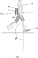
- the present invention provides a method of setting an exoskeleton 1 in motion.
- said exoskeleton 1 is an articulated mechanical system of the biped robotic device type, actuated and controlled, provided with two legs, more precisely accommodating a human operator presenting his lower limbs each secured to a leg of the exoskeleton 1 (in particular thanks to straps). It can thus be a more or less humanoid robot.
- the “setting into motion” translates in practice into alternating support on the legs, in a standing position, so as to produce a movement. This is most often walking, in particular forward, but it can be in practice any movement, including backwards, sideways, a half-turn, a sitting down, a getting up, etc.
- an exoskeleton movement is composed of a sequence of elementary trajectories such as steps, each step seeing a foot take off from the ground and then rest, before reversing roles (i.e. an alternation of steps of the left foot and the right foot).
- step we mean any displacement of a foot for any movement.
- the exoskeleton 1 has a plurality of degrees of freedom, i.e. joints movable (usually via rotation) relative to each other, which are each either “actuated” or “non-actuated”.
- An actuated degree of freedom means a joint provided with an actuator controlled by data processing means 11c, i.e. that this degree of freedom is controlled and that it can be acted upon.
- a non-actuated degree of freedom designates a joint without an actuator, that is to say that this degree of freedom follows its own dynamics and that the data processing means 11 have no direct control over it (but a priori an indirect control via the other actuated degrees of freedom).
- the present exoskeleton naturally comprises at least two actuated degrees of freedom, preferably a plurality. As we will see, some of these degrees of freedom can be "flexible”.
- the data processing means 11c designate a computer equipment (typically a processor, either external if the exoskeleton 1 is “remote controlled” but preferably embedded in the exoskeleton 1, see below) adapted to process instructions and generate commands intended for the different actuators.
- the latter can be electric, hydraulic, etc.
- the exoskeleton 1 comprises on each leg a foot structure comprising a support plane on which a foot of a leg of the person wearing the exoskeleton can come to rest.
- This support plane comprises for example a front platform and a rear platform, such that a foot pivot link connects the front platform to the rear platform, constituting a non-actuated degree of freedom.
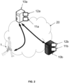
- the present trajectory and gait generation method may involve a first or even a second server 10a, 10b within an architecture such as represented by the Figure 2 .
- the first server 10a is a trajectory generation server
- the second server 10b is a possible learning server.
- the generation of a trajectory of the exoskeleton 1 can use a neural network, in particular of the “feedforward” type (FNN), as proposed in the application FR1910649 .
- the second server 10b is then a server for implementing a method for learning parameters of said neural network. It should be noted that the present method is not limited to the use of a neural network, and any known technique for generating the trajectory in its entirety, or even further, may be used.
- the second server 10b is most often a remote server while the first server 10a can be carried by the exoskeleton 1 for real-time operation, as represented by the figure 2 .
- the first server 10a implements the method of generating a trajectory of the exoskeleton 1 using a neural network using the parameters recovered from the second server 10b, and the exoskeleton 1 normally directly applies said trajectory generated in situ to start moving.
- Each of these servers 10a, 10b is typically a computer equipment connected to a wide area network 20 such as the Internet network for the exchange of data, even if in practice once the neural network has been learned and embedded on the second server 10b the communication can be interrupted, at least intermittently.
- Each comprises data processing means 11a, 11b of the processor type (in particular the data processing means 11b of the second server have a high computing power, because the learning is long and complex compared to the simple use of the learned neural network), and where appropriate data storage means 12a, 12b such as a computer memory, for example a hard disk.
- a training database can be stored by the memory 12b of the second server 10b.
- exoskeletons 1 there may be a plurality of exoskeletons 1 each carrying their first server 10a (which may then be of limited power and size, insofar as it only generates trajectories for the exoskeleton 1 to which it is dedicated), or a plurality of exoskeletons 1 each connected to a first more powerful server 10a and possibly merged with the second server 10b (and having the capacity to generate trajectories on the fly for all the exoskeletons 1).
- the term "trajectory" of the exoskeleton is traditionally understood to mean the evolutions of each degree of freedom (in particular actuated, but the non-actuated degrees can intervene in the control algorithms of the other degrees of freedom) expressed as a function of time or a phase variable.
- the term "position" of the exoskeleton 1 will mean the joint positions of the actuated degrees of freedom, which are advantageously six in number per leg, i.e. a position defined by a vector of dimension 12, even if one could for example take the Cartesian position of a characteristic point of the exoskeleton, for example its Center of Mass (CoM - we then have a vector of dimension 3 corresponding to the 3 positions along the 3 axes).
- a "complex" movement as a sequence of so-called “elementary” trajectories, where appropriate interspersed with transitions.
- elementary trajectory we most often mean a trajectory corresponding to a step, i.e. applied over the duration of the step so that starting from an initial state of the exoskeleton 1 at the beginning of a step (moment of foot contact), we arrive at the beginning of the next step.
- a periodic trajectory is a stable succession of elementary trajectories allowing walking, but as explained, this process applies to any movement.
- An elementary trajectory is associated with a given gait of the exoskeleton 1 (a gait being defined by an n-tuple of gait parameters), and allows to maintain this gait in a stable and feasible manner (i.e. as we will see, it respects all the constraints of an optimization problem and minimizes as much as possible a cost function).
- said gait parameters correspond to "characteristics" of the way of walking, such as the length of the steps, the walking frequency and the inclination of the bust, but also the height of the steps in the case of crossing stairs, the instantaneous angle of rotation for curved movements; and also to morphological characteristics of the operator (a subgroup of the gait parameters called patient parameters) such as his height, his weight, the length of the thighs or tibia, the position of the center of mass (value of the forward shift) and the lateral movement of the bust in the context of rehabilitation activity.
- step may be varied and depend on the type of step desired, for example a “flat foot” step, or a “rolled” step, etc. This method will not be limited to any type of step desired.
- Any transitions correspond to changes in gait, i.e. variations in the values of said gait parameters (for example an increase in the step length): knowing an initial set of gait parameters and a final set of gait parameters, and therefore an initial periodic trajectory (associated with the initial set of gait parameters) and a final periodic trajectory (associated with the final set of gait parameters), said transition is a trajectory fragment allowing to pass from the initial periodic trajectory to the final trajectory. Note that there must be “initial” or “final” transitions, corresponding to the start and end of the movement.
- the exoskeleton needs a "stabilizer", i.e. a dynamic controller applying the trajectory while ensuring the balance of the exoskeleton 1.
- a method called "admittance control" has proven effective for the stabilization of the gait of humanoid robots, as illustrated for example in the document Stéphane Caron, Abderrahmane Kheddar and Olivier Tempier, Stair Climbing Stabilization of the HRP-4 Humanoid Robot using Whole-body Admittance Control .
- Admittance control consists of estimating the state of the robot at any time, measuring its deviation from the reference trajectory, calculating a stabilizing force torsor and applying this force to the system via control of the joint positions, in the form of a stabilization loop.
- DCM Divergent-component of Motion
- the 1st equation shows that the DCM naturally diverges from the ZMP (hence the name “divergent”) while the 2nd equation shows that the CoM converges towards the DCM.
- a feedback control on the DCM thus makes it possible to calculate the said stabilizing force torso to be applied, and various admittance strategies called “whole-body admittance” (the document Stéphane Caron, Abderrahmane Kheddar and Olivier Tempier, Stair Climbing Stabilization of the HRP-4 Humanoid Robot using Whole-body Admittance Control gives the examples of ankle admittance, CoM admittance or the force difference between the feet) allow to determine kinematic instructions to be carried out so that the desired force is applied (using inverse kinematics in general).
- the admittance control method is not very robust. Specifically, the exoskeleton takes smaller steps than expected, drags its feet, or even vibrates, and the gait is neither comfortable for the operator nor safe.
- exoskeleton 1 cannot be considered a "rigid robot" in the same way as HRP-4 in the aforementioned paper, i.e. an articulated system whose dynamics can be sufficiently well described by the classical equations of rigid robotics.
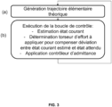
- said method of setting the exoskeleton 1 in motion begins with a step (a) of obtaining a theoretical elementary trajectory of the exoskeleton, corresponding for example to a step.
- This step may comprise the prior obtaining of at least one n-tuple of walking parameters defining a given step of the exoskeleton 1, or even a sequence of n-tuples of walking parameters that are progressively changed (for example due to new commands from the operator of the exoskeleton, in particular if the nature of the ground changes).
- obtaining can, as explained, directly involve the generation of the trajectory by the exoskeleton 1 (if for example it embeds the server 10a) or simply the reception of the trajectory by the network 20.
- the means 11c can provide the external server 10a with the walking parameters, and recover the trajectory in return.
- the operator may be provided as explained with a sensor vest 15 for detecting the configuration of his torso (orientation thereof).
- the direction in which the operator orients his torso is the one in which he wishes to walk and the speed may be given by the intensity with which he puts his torso forward (to what extent he leans).
- the start request may correspond to the operator pressing a button (or a particular posture) signifying his intention to start walking and therefore ordering the data processing means to determine said parameters.
- Certain parameters such as the instantaneous angle of rotation or the height of the steps in the event of crossing stairs may be predetermined or obtained by means of other sensors 13, 14.
- trajectory generation For the generation of the trajectory itself, we will not be limited to any known technique.
- optimization tools capable in particular of generating a given trajectory according to the chosen constraints and gait parameters.
- the problem of trajectory generation is formulated in the form of an optimal control problem that can be solved preferably by a so-called direct collocation algorithm, see the document Omar Harib et al., Feedback Control of an Exoskeleton for Paraplegics Toward Robustly Stable Hands-free Dynamic Walking .
- the generated elementary trajectory is called “theoretical”, as opposed to a “real” trajectory. Indeed, in a world free of any perturbation, one could simply apply the theoretical trajectory and the exoskeleton would automatically walk in accordance with this trajectory.
- the method comprises the execution of a control loop defining the evolution of a real position of the exoskeleton 1 so as to implement said real elementary trajectory close to said theoretical elementary trajectory, i.e. so that the exoskeleton 1 walks.
- state (current or expected) of the exoskeleton 1 we mean at least one parameter chosen from the positions, speeds and accelerations of the actuated degrees, position and speed of the Center of Mass (CoM), of the divergent component of motion (DCM), the position of the Center of Pressure (CoP), the position of the Zero Moment Point (ZMP); in particular the three parameters that are the positions of the Center of Mass (CoM), of the divergent component of motion (DCM) and Center of Pressure (CoP).
- the COP and the ZMP coincide (which is the case when the ground is substantially horizontal, even if irregular).
- we use the notation z to designate one or the other, and we will speak for convenience of CoP.
- we have an estimated current state and an expected state we have for each parameter a current version and an expected version.
- the current state is the real "measurable" state of the exoskeleton 1 corresponding to the real trajectory carried out.
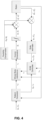
- each of its parameters is either directly measured (in particular positions of the actuated degrees and CoP), or estimated by the "state estimator" block of the figure 4 from the directly measured parameters (in particular CoM and DCM).
- the estimated positions of the CoM, DCM and CoP are respectively denoted c m , ⁇ m , and z m , as explained the DCM is in practice directly calculated from the CoM.
- the expected state is the theoretical “desired” state that exoskeleton 1 should take if the theoretical trajectory were applied as is, determined by the “pattern generator” block of the figure 4 .
- the expected positions of the CoM, DCM and CoP are respectively denoted c d , ⁇ d and Zd.
- the current DCM ⁇ m is not estimated only with the current CoM c m , but with respect to the speed of the CoM, with its target value, i.e. the one applied to the previous iteration ⁇ t .
- the target value is smoother while having the same average, and behaves like a filter improving the result.
- the determination of the force torsor to be applied to the exoskeleton 1 at the following iteration of the loop to compensate for the deviation between said current and expected states of the exoskeleton 1 advantageously comprises the implementation of a feedback control ("feedback", advantageously of the PID type) on at least one of said parameters defining the state of the exoskeleton, in particular the DCM, i.e. constitutes a DCM controller ("DCM control feedback" block in the figure 4 ).
- feedback advantageously of the PID type
- said force torsor to be applied to the exoskeleton 1 is defined as a position of the Center of Pressure (CoP) and/or the Zero Moment Point (ZMP).
- CoP Center of Pressure
- ZMP Zero Moment Point
- z d is the expected position of the CoP according to said theoretical elementary trajectory (calculated by the “Pattern Generator” block and provided directly to the admittance controller (the “Whole-Body Admittance” block) which will apply this effort), e ⁇ and e z the errors between the estimated and expected current CoPs and DCMs, and K p , K i and K d (adjustable) gains.
- This formula proves to be very effective for exoskeletons 1 receiving a human operator.
- the DCM controller (DCM feedback controller block) provides the last two terms of "deviation compensation" to the admittance controller (Whole-Body Admittance block), constituting the reference CoP noted z r in the figure 4 .
- Each iteration of the loop advantageously comprises, as explained, the application of said force torsor to the exoskeleton 1 (at the start of the loop), by means of the admittance controller itself (the Whole-Body Admittance block), which in particular generates so-called reference kinematic instructions (in contrast to the expected kinematic instructions generated from the theoretical trajectory), which can be converted, if necessary, into positions/speeds to be applied (called targets) of the actuated degrees using, for example, inverse kinematics and integration (if the inverse kinematics gives the accelerations).
- the possible inverse kinematics can comprise different hierarchical tasks (for example feet, CoM, pelvis then posture), depending on the admittance method used.
- the admittance controller indeed implements an ad-hoc method such as ankle admittance (changing the ankle joint position to apply the force), CoM admittance (requesting a movement of the center of mass), the force difference between the feet (when in double support, raise or lower the feet, using force sensors under the feet), or any other strategy of changing the position setpoint to control the forces.
- the determination of the effort torsor and/or its application to the exoskeleton 1 takes into account a flexibility model of the exoskeleton 1 relative to a rigid robot, i.e. here a conventional biped robot not receiving a human operator, and thus being able to be considered as an isolated system.
- a rigid robot i.e. here a conventional biped robot not receiving a human operator
- the opposition between rigid robotics and flexible (or “soft”) robotics is well known to those skilled in the art and these terms have a well-defined meaning.
- exoskeleton 1 is "flexible”, to model it using a model, and to apply this model either when determining the force torsor to be applied to the exoskeleton, or when said application of the force torsor to the exoskeleton.
- This is an open loop correction (feed-forward), the values of the parameters (joint instructions) are just modified, i.e. corrected (their initial value is taken into account) or directly replaced.
- a “Flexibility compensator” module generates the offsets and adds them to the target values to correct them before they are sent to the actuators.
- the said model which allows to determine the offsets is advantageously predetermined experimentally, from real stable steps and/or simulations (for example thanks to the Jiminy simulator). For example, we start with the simulation of stable steps, then we refine the model on real steps on which the stability is tested.
- the said flexibility model models for example a flexible actuated degree as a spring, the stiffness of which has been determined experimentally.
- this method may also include (or not), as shown in the figure 4 , removing offsets from measured positions to cancel flexibility compensation.
- the said flexibility model is applied so as to modify the expected position of the CoP z d , used both by the DCM controller and the admittance controller.
- the CoP does not need to be fully dynamically consistent with other parameters including the CoM.
- a flexibility compensation can be performed when changing the contact foot (see below), especially if the contact foot is changed earlier than expected due to unexpected ground contact (typical consequence of flexibilities).
- a modified CoP can be calculated independently of the joint positions.
- the flexibility model can take the form of a first-order filter that can be applied to the expected CoP.
- the filter will naturally vary the expected CoP between the final value of the first step and the initial value of the second step, instead of changing abruptly.
- MPC Model Preview Control
- any other live rescheduling strategy that allows for a smooth transition from one foot to the other would be feasible.
- Said flexibility model thus defines at least one parameter of the state of the exoskeleton to be replaced by an average value observed on real stable steps, this replacement being preferentially directly at the output of the admittance controller, before inverse kinematics.
- the admittance controller loop can create a "stability zone" around an already stable (proven) step, which allows for better overall stability than when one also has to perform the work of stabilizing an unstable base step.
- Steps (a) and (b) can be repeated so as to make the exoskeleton 1 walk by a succession of real elementary trajectories each corresponding to a step.
- step (a) starts from an initial position
- step (c) advantageously comprising the determination of a final position of the exoskeleton 1 at the end of said real elementary trajectory, said final position being used as the initial position at the next occurrence of step (a).
- step (a) consists of modifying the periodic trajectory (for the next elementary trajectory).
- the invention relates to the exoskeleton 1, for implementing the method according to the first aspect, and according to a third aspect the system comprising the exoskeleton as well as a possible server 10a, possibly combined.
- the exoskeleton 1 comprises data processing means 11c configured for implementing the method according to the second aspect, as well as that if necessary data storage means 12 (in particular those of the first server 10a), inertial measurement means 14 (inertia unit), means for detecting the impact of the feet on the ground 13 and where appropriate estimating the contact forces (contact sensors or possibly pressure sensors), and/or a sensor vest 15.
- data processing means 11c configured for implementing the method according to the second aspect, as well as that if necessary data storage means 12 (in particular those of the first server 10a), inertial measurement means 14 (inertia unit), means for detecting the impact of the feet on the ground 13 and where appropriate estimating the contact forces (contact sensors or possibly pressure sensors), and/or a sensor vest 15.
- It has a plurality of degrees of freedom including at least one degree of freedom actuated by an actuator controlled by the data processing means 11c for the execution of said controller.
- the first server 10a comprises data processing means 11a for generating said theoretical elementary trajectory and providing it to the exoskeleton in step (a), in particular upon receipt of the initial position of the exoskeleton 1 at step start and any walking parameters.
- the invention relates to a computer program product comprising code instructions for the execution (on the processing means 11c), of a method according to the first aspect of setting an exoskeleton 1 in motion, as well as storage means readable by computer equipment on which this computer program product is found.
Landscapes
- Health & Medical Sciences (AREA)
- Engineering & Computer Science (AREA)
- General Health & Medical Sciences (AREA)
- Robotics (AREA)
- Mechanical Engineering (AREA)
- Life Sciences & Earth Sciences (AREA)
- Physical Education & Sports Medicine (AREA)
- Rehabilitation Therapy (AREA)
- Pain & Pain Management (AREA)
- Animal Behavior & Ethology (AREA)
- Epidemiology (AREA)
- Public Health (AREA)
- Veterinary Medicine (AREA)
- Orthopedic Medicine & Surgery (AREA)
- Manipulator (AREA)
- Rehabilitation Tools (AREA)
Claims (17)
- Verfahren zum In-Bewegung-Setzen eines zweibeinigen Exoskeletts (1), das einen menschlichen Bediener aufnimmt, wobei das Verfahren das Umsetzen der folgenden Schritte durch Datenverarbeitungsmittel (11c) des Exoskeletts (1) umfasst:(a) Erzielen einer theoretischen elementaren Trajektorie des Exoskeletts (1);(b) Ausführen einer Steuerschleife, welche die Entwicklung einer tatsächlichen Position des Exoskeletts (1) definiert, um eine tatsächliche elementare Trajektorie umzusetzen, die zu der theoretischen elementaren Trajektorie benachbart ist, umfassend bei jeder Iteration der Schleife:wobei die Bestimmung des Krafttorsors und/oder seine Anwendung auf das Exoskelett (1) ein Flexibilitätsmodell des Exoskeletts (1) im Verhältnis zu einem starren Roboter berücksichtigen.- Schätzen eines aktuellen Zustands des Exoskeletts (1) gemäß der tatsächlichen Position;- Bestimmen eines Krafttorsors, der bei der folgenden Iteration der Schleife auf das Exoskelett (1) anzuwenden ist, um eine Abweichung zwischen dem geschätzten aktuellen Zustand des Exoskeletts (1) und einem erwarteten Zustand des Exoskeletts (1) gemäß der theoretischen elementare Trajektorie zu kompensieren;
- Verfahren nach Anspruch 1, umfassend das Wiederholen der Schritte (a) und (b), um zu bewirken, dass das Exoskelett (1) durch eine Reihe von tatsächlichen elementaren Trajektorien, die jeweils einem Schritt entsprechen, geht.
- Verfahren nach Anspruch 2, wobei die theoretische elementare Trajektorie, die in Schritt (a) erzielt wird, von einer Ausgangsposition ausgeht, wobei der Schritt (b) die Bestimmung einer Endposition des Exoskeletts (1) am Ende der tatsächlichen elementaren Trajektorie umfasst, wobei die Endposition als Anfangsposition beim nächsten Vorkommen von Schritt (a) verwendet wird.
- Verfahren nach einem der Ansprüche 1 bis 3, wobei der Schritt (b) am Anfang jeder Iteration der Schleife die Anwendung auf das Exoskelett (1) des Krafttorsors, der in der vorhergehenden Iteration bestimmt wurde, mittels eines Admittanzsteuergeräts umfasst.
- Verfahren nach einem der Ansprüche 1 bis 4, wobei die Bestimmung eines Krafttorsors, der auf das Exoskelett (1) anzuwenden ist, um die Abweichung zwischen dem geschätzten aktuellen Zustand des Exoskeletts (1) und einem erwarteten Zustand des Exoskeletts (1) gemäß der theoretischen elementaren Trajektorie zu kompensieren, das Umsetzen einer Rückkopplungssteuerung an mindestens einem Parameter, der den Zustand des Exoskeletts definiert, umfasst.
- Verfahren nach einem der Ansprüche 1 bis 5, wobei die Position des Exoskeletts (1) durch einen Vektor der Gelenkpositionen der betätigten Freiheitsgrade des Exoskeletts (1) definiert wird, wobei der Zustand des Exoskeletts (1) durch mindestens einen Parameter definiert wird, der aus den Positionen, den Geschwindigkeiten und den Beschleunigungen der betätigten Grade, den Positionen und Geschwindigkeiten eines Massenmittelpunkts, CoM, einer divergenten Bewegungskomponente, DCM, der Position eines Druckmittelpunkts, CoP, und der Position eines Nullmomentpunkts, ZMP, gewählt wird; insbesondere durch die Positionen des Massenmittelpunkts, CoM, der divergenten Bewegungskomponente, DCM, und des Druckmittelpunkts, CoP, definiert wird.
- Verfahren nach Anspruch 5 und 6 kombiniert, wobei die Rückkopplungssteuerung in der Position der DCM umgesetzt wird.
- Verfahren nach einem der Ansprüche 6 und 7, wobei der Krafttorsor, der auf das Exoskelett (1) anzuwenden ist, durch eine Position des CoP definiert wird.
- Verfahren nach Anspruch 7, wobei der Krafttorsor, der auf das Exoskelett (1) anzuwenden ist, bestimmt wird, indem zu der erwarteten Position des CoP gemäß der theoretischen elementaren Trajektorie mindestens ein Term für den Fehler zwischen der geschätzten und der erwarteten aktuellen Position des CoP und ein Term für den Fehler zwischen der geschätzten und der erwarteten aktuellen Position der DCM, insbesondere gemäß der Formel

- Verfahren nach einem der Ansprüche 6 bis 9, wobei das Flexibilitätsmodell eine Änderung der erwarteten Position des CoP definiert, die verwendet wird, um den Krafttorsor zu bestimmen.
- Verfahren nach einem der Ansprüche 1 bis 10, wobei das Exoskelett (1) mindestens einen flexiblen betätigten Freiheitsgrad aufweist, wobei das Flexibilitätsmodell einen Versatz definiert, der auf eine angestrebte Position und/oder Geschwindigkeit des flexiblen betätigten Freiheitsgrads, die infolge der Anwendung des Krafttorsors bestimmt werden, anzuwenden ist.
- Verfahren nach einem der Ansprüche 1 bis 11, wobei das Flexibilitätsmodell mindestens einen Parameter des Zustands des Exoskeletts (1) definiert, der durch einen Mittelwert zu ersetzen ist, der an stabilen tatsächlichen Schritten festgestellt wird.
- Verfahren nach einem der Ansprüche 1 bis 12, wobei das Flexibilitätsmodell aus stabilen tatsächlichen Schritten und/oder aus Simulationen versuchsmäßig vorbestimmt wird.
- Exoskelett (1), umfassend Datenverarbeitungsmittel (11c), die dazu konfiguriert sind, ein Verfahren nach einem der Ansprüche 1 bis 13 zum In-Bewegung-Setzen des Exoskeletts (1) umzusetzen.
- System, umfassend einen Server (10a) und das Exoskelett (1) nach Anspruch 14, wobei der Server (10a) Datenverarbeitungsmittel (11a) umfasst, die dazu konfiguriert sind, die theoretische elementare Trajektorie zu generieren und sie dem Exoskelett in Schritt (a) bereitzustellen.
- Computerprogrammprodukt, umfassend Codeanweisungen zum Durchführen eines Verfahrens nach einem der Ansprüche 1 bis 13 zum In-Bewegung-Setzen eines Exoskeletts (1), wenn das Programm auf einem Computer ausgeführt wird.
- Speichermittel, das von einer Computereinrichtung lesbar ist, auf der ein Computerprogrammprodukt Codeanweisungen für die Ausführung eines Verfahrens nach einem der Ansprüche 1 bis 13 zum In-Bewegung-Setzen eines Exoskeletts (1) umfasst.
Applications Claiming Priority (2)
| Application Number | Priority Date | Filing Date | Title |
|---|---|---|---|
| FR2013340A FR3117393B1 (fr) | 2020-12-16 | 2020-12-16 | Procédé de mise en mouvement d’UN exosquelette |
| PCT/FR2021/052335 WO2022129784A1 (fr) | 2020-12-16 | 2021-12-15 | Procédé de mise en mouvement d'un exosquelette |
Publications (3)
| Publication Number | Publication Date |
|---|---|
| EP4263146A1 EP4263146A1 (de) | 2023-10-25 |
| EP4263146B1 true EP4263146B1 (de) | 2024-12-18 |
| EP4263146C0 EP4263146C0 (de) | 2024-12-18 |
Family
ID=74860101
Family Applications (1)
| Application Number | Title | Priority Date | Filing Date |
|---|---|---|---|
| EP21851677.1A Active EP4263146B1 (de) | 2020-12-16 | 2021-12-15 | Verfahren zum bewegen eines exoskeletts |
Country Status (9)
| Country | Link |
|---|---|
| US (1) | US20240000648A1 (de) |
| EP (1) | EP4263146B1 (de) |
| JP (1) | JP2024502726A (de) |
| KR (1) | KR20230120651A (de) |
| CN (1) | CN116635192A (de) |
| CA (1) | CA3204302A1 (de) |
| ES (1) | ES3014079T3 (de) |
| FR (1) | FR3117393B1 (de) |
| WO (1) | WO2022129784A1 (de) |
Families Citing this family (7)
| Publication number | Priority date | Publication date | Assignee | Title |
|---|---|---|---|---|
| FR3139277B1 (fr) | 2022-09-06 | 2024-08-30 | Wandercraft | Procédé de mise en mouvement stabilisée d’un exosquelette bipède |
| CN118131801B (zh) * | 2022-11-24 | 2025-06-03 | 北京小米机器人技术有限公司 | 运动控制方法及装置、运动轨迹生成方法及装置 |
| CN116922396B (zh) * | 2023-09-07 | 2023-11-17 | 贵州航天控制技术有限公司 | 一种外骨骼系统的助力控制方法 |
| CN117021118B (zh) * | 2023-10-08 | 2023-12-15 | 中北大学 | 一种并联机器人数字孪生轨迹误差动态补偿方法 |
| CN119098934A (zh) * | 2024-08-19 | 2024-12-10 | 同济大学 | 基于ai共驾的外骨骼共享控制方法、系统、设备和存储介质 |
| CN119292321A (zh) * | 2024-08-29 | 2025-01-10 | 中国科学院深圳先进技术研究院 | 一种外骨骼在未知地形下自平衡行走的控制方法 |
| CN120038762B (zh) * | 2025-04-23 | 2025-07-11 | 上海术理智能科技有限公司 | 基于动作意图识别的轨迹生成方法、系统与介质 |
Family Cites Families (14)
| Publication number | Priority date | Publication date | Assignee | Title |
|---|---|---|---|---|
| JPS60199450A (ja) * | 1984-03-26 | 1985-10-08 | 工業技術院長 | 下肢障害者用動力装具 |
| EP2238894B1 (de) * | 2009-04-07 | 2011-11-02 | Syco Di Hedvig Haberl & C. S.A.S. | System zur Steuerung einer haptischen Exoskelettvorrichtung zu Rehabilitationszwecken und entsprechende haptische Exoskelettvorrichtung |
| EP2497610B1 (de) * | 2011-03-09 | 2014-10-22 | Syco Di Hedvig Haberl & C. S.A.S. | System zur Steuerung einer Robotervorrichtung während des Gehens, insbesondere zu Rehabilitationszwecken, sowie zugehörige Robotervorrichtung |
| JP2015529574A (ja) * | 2012-09-17 | 2015-10-08 | プレジデント アンド フェローズ オブ ハーバード カレッジ | 人間動作を補助するための軟性外骨格スーツ |
| PL2968052T3 (pl) * | 2013-03-14 | 2022-02-07 | Ekso Bionics, Inc. | Zasilany układ ortotyczny do naziemnej rehabilitacji kooperacyjnej |
| JP2017514640A (ja) | 2014-03-21 | 2017-06-08 | ワンダークラフト | 足構造を有するエクソスケルトン |
| FR3018681B1 (fr) | 2014-03-21 | 2016-04-15 | Wandercraft | Exosquelette comprenant une structure de bassin |
| US10406676B2 (en) * | 2014-05-06 | 2019-09-10 | Sarcos Lc | Energy recovering legged robotic device |
| CN105538313B (zh) * | 2016-03-14 | 2018-02-02 | 中国计量大学 | 一种工业机器人激光轨迹检测装置 |
| FR3061653B1 (fr) * | 2017-01-10 | 2019-05-31 | Wandercraft | Procede de mise en mouvement d'un exosquelette |
| FR3068236B1 (fr) * | 2017-06-29 | 2019-07-26 | Wandercraft | Procede de mise en mouvement d'un exosquelette |
| US20190159954A1 (en) * | 2017-11-28 | 2019-05-30 | Steering Solutions Ip Holding Corporation | Biomechanical assistive device for collecting clinical data |
| DE102018211050A1 (de) * | 2018-07-04 | 2020-01-09 | Audi Ag | Verfahren zum Betreiben eines Exoskelett-System, Exoskelett-System sowie zentrale Servereinheit |
| WO2020133288A1 (zh) * | 2018-12-28 | 2020-07-02 | 深圳市优必选科技有限公司 | 一种双足机器人步态控制方法以及双足机器人 |
-
2020
- 2020-12-16 FR FR2013340A patent/FR3117393B1/fr active Active
-
2021
- 2021-12-15 EP EP21851677.1A patent/EP4263146B1/de active Active
- 2021-12-15 WO PCT/FR2021/052335 patent/WO2022129784A1/fr not_active Ceased
- 2021-12-15 KR KR1020237023203A patent/KR20230120651A/ko active Pending
- 2021-12-15 CN CN202180085261.6A patent/CN116635192A/zh active Pending
- 2021-12-15 CA CA3204302A patent/CA3204302A1/fr active Pending
- 2021-12-15 JP JP2023536350A patent/JP2024502726A/ja active Pending
- 2021-12-15 US US18/039,079 patent/US20240000648A1/en active Pending
- 2021-12-15 ES ES21851677T patent/ES3014079T3/es active Active
Also Published As
| Publication number | Publication date |
|---|---|
| FR3117393B1 (fr) | 2023-01-06 |
| CN116635192A (zh) | 2023-08-22 |
| EP4263146C0 (de) | 2024-12-18 |
| CA3204302A1 (fr) | 2022-06-23 |
| US20240000648A1 (en) | 2024-01-04 |
| KR20230120651A (ko) | 2023-08-17 |
| EP4263146A1 (de) | 2023-10-25 |
| WO2022129784A1 (fr) | 2022-06-23 |
| JP2024502726A (ja) | 2024-01-23 |
| ES3014079T3 (en) | 2025-04-16 |
| FR3117393A1 (fr) | 2022-06-17 |
Similar Documents
| Publication | Publication Date | Title |
|---|---|---|
| EP4263146B1 (de) | Verfahren zum bewegen eines exoskeletts | |
| EP4210911B1 (de) | Verfahren zum bewegen eines exoskeletts | |
| EP2740012B1 (de) | Roboter mit gelenken mit variabler steifigkeit und verfahren zur berechnung der optimierten steifigkeit | |
| EP3568266B1 (de) | Verfahren zum bewegen eines exoskeletts | |
| EP2448810B1 (de) | Verfahren zur steuerung der gehbewegung eines beweglichen roboters und roboter mit diesem verfahren | |
| EP4103131B1 (de) | Verfahren zur erzeugung einer trajektorie eines exoskeletts und zur einstellung des exoskeletts in bewegung | |
| EP4034344A1 (de) | Verfahren zum erlernen von parametern eines neuronalen netzes, zur erzeugung einer trajektorie eines exoskeletts und zur ingangsetzung des exoskeletts | |
| EP2766251A1 (de) | Verfahren zur steuerung eines roboters mit mindestens zwei beinen | |
| JP2025508817A (ja) | ニューラルネットワークをトレーニングし、二足ロボットを安定化するためにニューラルネットワークを使用する方法 | |
| JP4587699B2 (ja) | ロボット装置及びその制御方法 | |
| EP4412801B1 (de) | Verfahren zum bewegen eines exoskeletts | |
| WO2024052618A1 (fr) | Procede de mise en mouvement stabilisee d'un exosquelette bipede | |
| Bondada | Capture Point Control in Thruster-Assisted Bipedal Locomotion | |
| Liu | Walking control for a bipedal model with exoskeleton applications | |
| Roos | Design of a direct collocation model predictive control framework for legged locomotion based on whole-body dynamics and explicit contact phases |
Legal Events
| Date | Code | Title | Description |
|---|---|---|---|
| STAA | Information on the status of an ep patent application or granted ep patent |
Free format text: STATUS: UNKNOWN |
|
| STAA | Information on the status of an ep patent application or granted ep patent |
Free format text: STATUS: THE INTERNATIONAL PUBLICATION HAS BEEN MADE |
|
| PUAI | Public reference made under article 153(3) epc to a published international application that has entered the european phase |
Free format text: ORIGINAL CODE: 0009012 |
|
| STAA | Information on the status of an ep patent application or granted ep patent |
Free format text: STATUS: REQUEST FOR EXAMINATION WAS MADE |
|
| 17P | Request for examination filed |
Effective date: 20230713 |
|
| AK | Designated contracting states |
Kind code of ref document: A1 Designated state(s): AL AT BE BG CH CY CZ DE DK EE ES FI FR GB GR HR HU IE IS IT LI LT LU LV MC MK MT NL NO PL PT RO RS SE SI SK SM TR |
|
| DAV | Request for validation of the european patent (deleted) | ||
| DAX | Request for extension of the european patent (deleted) | ||
| GRAP | Despatch of communication of intention to grant a patent |
Free format text: ORIGINAL CODE: EPIDOSNIGR1 |
|
| STAA | Information on the status of an ep patent application or granted ep patent |
Free format text: STATUS: GRANT OF PATENT IS INTENDED |
|
| INTG | Intention to grant announced |
Effective date: 20240730 |
|
| GRAS | Grant fee paid |
Free format text: ORIGINAL CODE: EPIDOSNIGR3 |
|
| GRAA | (expected) grant |
Free format text: ORIGINAL CODE: 0009210 |
|
| STAA | Information on the status of an ep patent application or granted ep patent |
Free format text: STATUS: THE PATENT HAS BEEN GRANTED |
|
| AK | Designated contracting states |
Kind code of ref document: B1 Designated state(s): AL AT BE BG CH CY CZ DE DK EE ES FI FR GB GR HR HU IE IS IT LI LT LU LV MC MK MT NL NO PL PT RO RS SE SI SK SM TR |
|
| REG | Reference to a national code |
Ref country code: CH Ref legal event code: EP |
|
| REG | Reference to a national code |
Ref country code: DE Ref legal event code: R096 Ref document number: 602021023706 Country of ref document: DE |
|
| REG | Reference to a national code |
Ref country code: IE Ref legal event code: FG4D Free format text: LANGUAGE OF EP DOCUMENT: FRENCH |
|
| U01 | Request for unitary effect filed |
Effective date: 20250114 |
|
| U07 | Unitary effect registered |
Designated state(s): AT BE BG DE DK EE FI FR IT LT LU LV MT NL PT RO SE SI Effective date: 20250120 |
|
| PG25 | Lapsed in a contracting state [announced via postgrant information from national office to epo] |
Ref country code: HR Free format text: LAPSE BECAUSE OF FAILURE TO SUBMIT A TRANSLATION OF THE DESCRIPTION OR TO PAY THE FEE WITHIN THE PRESCRIBED TIME-LIMIT Effective date: 20241218 |
|
| REG | Reference to a national code |
Ref country code: ES Ref legal event code: FG2A Ref document number: 3014079 Country of ref document: ES Kind code of ref document: T3 Effective date: 20250416 |
|
| PG25 | Lapsed in a contracting state [announced via postgrant information from national office to epo] |
Ref country code: NO Free format text: LAPSE BECAUSE OF FAILURE TO SUBMIT A TRANSLATION OF THE DESCRIPTION OR TO PAY THE FEE WITHIN THE PRESCRIBED TIME-LIMIT Effective date: 20250318 |
|
| PG25 | Lapsed in a contracting state [announced via postgrant information from national office to epo] |
Ref country code: GR Free format text: LAPSE BECAUSE OF FAILURE TO SUBMIT A TRANSLATION OF THE DESCRIPTION OR TO PAY THE FEE WITHIN THE PRESCRIBED TIME-LIMIT Effective date: 20250319 |
|
| PG25 | Lapsed in a contracting state [announced via postgrant information from national office to epo] |
Ref country code: RS Free format text: LAPSE BECAUSE OF FAILURE TO SUBMIT A TRANSLATION OF THE DESCRIPTION OR TO PAY THE FEE WITHIN THE PRESCRIBED TIME-LIMIT Effective date: 20250318 |
|
| PG25 | Lapsed in a contracting state [announced via postgrant information from national office to epo] |
Ref country code: SM Free format text: LAPSE BECAUSE OF FAILURE TO SUBMIT A TRANSLATION OF THE DESCRIPTION OR TO PAY THE FEE WITHIN THE PRESCRIBED TIME-LIMIT Effective date: 20241218 |
|
| PG25 | Lapsed in a contracting state [announced via postgrant information from national office to epo] |
Ref country code: PL Free format text: LAPSE BECAUSE OF FAILURE TO SUBMIT A TRANSLATION OF THE DESCRIPTION OR TO PAY THE FEE WITHIN THE PRESCRIBED TIME-LIMIT Effective date: 20241218 |
|
| PG25 | Lapsed in a contracting state [announced via postgrant information from national office to epo] |
Ref country code: IS Free format text: LAPSE BECAUSE OF FAILURE TO SUBMIT A TRANSLATION OF THE DESCRIPTION OR TO PAY THE FEE WITHIN THE PRESCRIBED TIME-LIMIT Effective date: 20250418 |
|
| PG25 | Lapsed in a contracting state [announced via postgrant information from national office to epo] |
Ref country code: SK Free format text: LAPSE BECAUSE OF FAILURE TO SUBMIT A TRANSLATION OF THE DESCRIPTION OR TO PAY THE FEE WITHIN THE PRESCRIBED TIME-LIMIT Effective date: 20241218 |
|
| PG25 | Lapsed in a contracting state [announced via postgrant information from national office to epo] |
Ref country code: CZ Free format text: LAPSE BECAUSE OF FAILURE TO SUBMIT A TRANSLATION OF THE DESCRIPTION OR TO PAY THE FEE WITHIN THE PRESCRIBED TIME-LIMIT Effective date: 20241218 |
|
| PLBE | No opposition filed within time limit |
Free format text: ORIGINAL CODE: 0009261 |
|
| STAA | Information on the status of an ep patent application or granted ep patent |
Free format text: STATUS: NO OPPOSITION FILED WITHIN TIME LIMIT |
|
| 26N | No opposition filed |
Effective date: 20250919 |