EP4262045A1 - Battery charging management system and battery charging management method - Google Patents
Battery charging management system and battery charging management method Download PDFInfo
- Publication number
- EP4262045A1 EP4262045A1 EP22168193.5A EP22168193A EP4262045A1 EP 4262045 A1 EP4262045 A1 EP 4262045A1 EP 22168193 A EP22168193 A EP 22168193A EP 4262045 A1 EP4262045 A1 EP 4262045A1
- Authority
- EP
- European Patent Office
- Prior art keywords
- charging
- battery
- information
- units
- control unit
- Prior art date
- Legal status (The legal status is an assumption and is not a legal conclusion. Google has not performed a legal analysis and makes no representation as to the accuracy of the status listed.)
- Pending
Links
- 238000007726 management method Methods 0.000 title claims description 112
- 238000000034 method Methods 0.000 claims abstract description 45
- 238000004891 communication Methods 0.000 claims abstract description 40
- 230000008569 process Effects 0.000 claims abstract description 39
- 230000005540 biological transmission Effects 0.000 claims abstract description 8
- 238000010413 gardening Methods 0.000 claims abstract description 6
- 238000010276 construction Methods 0.000 claims abstract description 5
- 239000002689 soil Substances 0.000 claims abstract description 4
- 238000012913 prioritisation Methods 0.000 claims description 28
- 238000011161 development Methods 0.000 description 10
- 230000018109 developmental process Effects 0.000 description 10
- 230000032683 aging Effects 0.000 description 7
- 230000001419 dependent effect Effects 0.000 description 5
- 238000010586 diagram Methods 0.000 description 4
- 230000001360 synchronised effect Effects 0.000 description 4
- 238000003860 storage Methods 0.000 description 3
- 230000008901 benefit Effects 0.000 description 2
- 230000008859 change Effects 0.000 description 2
- 238000011156 evaluation Methods 0.000 description 2
- 238000003971 tillage Methods 0.000 description 2
- 230000009471 action Effects 0.000 description 1
- 230000006978 adaptation Effects 0.000 description 1
- OJIJEKBXJYRIBZ-UHFFFAOYSA-N cadmium nickel Chemical compound [Ni].[Cd] OJIJEKBXJYRIBZ-UHFFFAOYSA-N 0.000 description 1
- 238000013461 design Methods 0.000 description 1
- 230000007613 environmental effect Effects 0.000 description 1
- 238000003898 horticulture Methods 0.000 description 1
- 229910001416 lithium ion Inorganic materials 0.000 description 1
- 238000004519 manufacturing process Methods 0.000 description 1
- 239000000463 material Substances 0.000 description 1
- 229910052987 metal hydride Inorganic materials 0.000 description 1
- 230000003287 optical effect Effects 0.000 description 1
- 238000005457 optimization Methods 0.000 description 1
- 238000013021 overheating Methods 0.000 description 1
- 238000012545 processing Methods 0.000 description 1
- 230000009467 reduction Effects 0.000 description 1
- 230000000717 retained effect Effects 0.000 description 1
- 238000010187 selection method Methods 0.000 description 1
- 238000012546 transfer Methods 0.000 description 1
Images


Classifications
-
- H—ELECTRICITY
- H02—GENERATION; CONVERSION OR DISTRIBUTION OF ELECTRIC POWER
- H02J—CIRCUIT ARRANGEMENTS OR SYSTEMS FOR SUPPLYING OR DISTRIBUTING ELECTRIC POWER; SYSTEMS FOR STORING ELECTRIC ENERGY
- H02J7/00—Circuit arrangements for charging or depolarising batteries or for supplying loads from batteries
- H02J7/00032—Circuit arrangements for charging or depolarising batteries or for supplying loads from batteries characterised by data exchange
- H02J7/00036—Charger exchanging data with battery
-
- B—PERFORMING OPERATIONS; TRANSPORTING
- B60—VEHICLES IN GENERAL
- B60L—PROPULSION OF ELECTRICALLY-PROPELLED VEHICLES; SUPPLYING ELECTRIC POWER FOR AUXILIARY EQUIPMENT OF ELECTRICALLY-PROPELLED VEHICLES; ELECTRODYNAMIC BRAKE SYSTEMS FOR VEHICLES IN GENERAL; MAGNETIC SUSPENSION OR LEVITATION FOR VEHICLES; MONITORING OPERATING VARIABLES OF ELECTRICALLY-PROPELLED VEHICLES; ELECTRIC SAFETY DEVICES FOR ELECTRICALLY-PROPELLED VEHICLES
- B60L53/00—Methods of charging batteries, specially adapted for electric vehicles; Charging stations or on-board charging equipment therefor; Exchange of energy storage elements in electric vehicles
- B60L53/60—Monitoring or controlling charging stations
- B60L53/62—Monitoring or controlling charging stations in response to charging parameters, e.g. current, voltage or electrical charge
-
- B—PERFORMING OPERATIONS; TRANSPORTING
- B60—VEHICLES IN GENERAL
- B60L—PROPULSION OF ELECTRICALLY-PROPELLED VEHICLES; SUPPLYING ELECTRIC POWER FOR AUXILIARY EQUIPMENT OF ELECTRICALLY-PROPELLED VEHICLES; ELECTRODYNAMIC BRAKE SYSTEMS FOR VEHICLES IN GENERAL; MAGNETIC SUSPENSION OR LEVITATION FOR VEHICLES; MONITORING OPERATING VARIABLES OF ELECTRICALLY-PROPELLED VEHICLES; ELECTRIC SAFETY DEVICES FOR ELECTRICALLY-PROPELLED VEHICLES
- B60L53/00—Methods of charging batteries, specially adapted for electric vehicles; Charging stations or on-board charging equipment therefor; Exchange of energy storage elements in electric vehicles
- B60L53/60—Monitoring or controlling charging stations
- B60L53/65—Monitoring or controlling charging stations involving identification of vehicles or their battery types
-
- B—PERFORMING OPERATIONS; TRANSPORTING
- B60—VEHICLES IN GENERAL
- B60L—PROPULSION OF ELECTRICALLY-PROPELLED VEHICLES; SUPPLYING ELECTRIC POWER FOR AUXILIARY EQUIPMENT OF ELECTRICALLY-PROPELLED VEHICLES; ELECTRODYNAMIC BRAKE SYSTEMS FOR VEHICLES IN GENERAL; MAGNETIC SUSPENSION OR LEVITATION FOR VEHICLES; MONITORING OPERATING VARIABLES OF ELECTRICALLY-PROPELLED VEHICLES; ELECTRIC SAFETY DEVICES FOR ELECTRICALLY-PROPELLED VEHICLES
- B60L53/00—Methods of charging batteries, specially adapted for electric vehicles; Charging stations or on-board charging equipment therefor; Exchange of energy storage elements in electric vehicles
- B60L53/60—Monitoring or controlling charging stations
- B60L53/66—Data transfer between charging stations and vehicles
-
- H—ELECTRICITY
- H01—ELECTRIC ELEMENTS
- H01M—PROCESSES OR MEANS, e.g. BATTERIES, FOR THE DIRECT CONVERSION OF CHEMICAL ENERGY INTO ELECTRICAL ENERGY
- H01M10/00—Secondary cells; Manufacture thereof
- H01M10/42—Methods or arrangements for servicing or maintenance of secondary cells or secondary half-cells
- H01M10/44—Methods for charging or discharging
- H01M10/441—Methods for charging or discharging for several batteries or cells simultaneously or sequentially
-
- H—ELECTRICITY
- H02—GENERATION; CONVERSION OR DISTRIBUTION OF ELECTRIC POWER
- H02J—CIRCUIT ARRANGEMENTS OR SYSTEMS FOR SUPPLYING OR DISTRIBUTING ELECTRIC POWER; SYSTEMS FOR STORING ELECTRIC ENERGY
- H02J7/00—Circuit arrangements for charging or depolarising batteries or for supplying loads from batteries
- H02J7/0013—Circuit arrangements for charging or depolarising batteries or for supplying loads from batteries acting upon several batteries simultaneously or sequentially
-
- H—ELECTRICITY
- H02—GENERATION; CONVERSION OR DISTRIBUTION OF ELECTRIC POWER
- H02J—CIRCUIT ARRANGEMENTS OR SYSTEMS FOR SUPPLYING OR DISTRIBUTING ELECTRIC POWER; SYSTEMS FOR STORING ELECTRIC ENERGY
- H02J7/00—Circuit arrangements for charging or depolarising batteries or for supplying loads from batteries
- H02J7/0047—Circuit arrangements for charging or depolarising batteries or for supplying loads from batteries with monitoring or indicating devices or circuits
-
- H—ELECTRICITY
- H02—GENERATION; CONVERSION OR DISTRIBUTION OF ELECTRIC POWER
- H02J—CIRCUIT ARRANGEMENTS OR SYSTEMS FOR SUPPLYING OR DISTRIBUTING ELECTRIC POWER; SYSTEMS FOR STORING ELECTRIC ENERGY
- H02J7/00—Circuit arrangements for charging or depolarising batteries or for supplying loads from batteries
- H02J7/0063—Circuit arrangements for charging or depolarising batteries or for supplying loads from batteries with circuits adapted for supplying loads from the battery
-
- H—ELECTRICITY
- H02—GENERATION; CONVERSION OR DISTRIBUTION OF ELECTRIC POWER
- H02J—CIRCUIT ARRANGEMENTS OR SYSTEMS FOR SUPPLYING OR DISTRIBUTING ELECTRIC POWER; SYSTEMS FOR STORING ELECTRIC ENERGY
- H02J7/00—Circuit arrangements for charging or depolarising batteries or for supplying loads from batteries
- H02J7/007—Regulation of charging or discharging current or voltage
- H02J7/00712—Regulation of charging or discharging current or voltage the cycle being controlled or terminated in response to electric parameters
Definitions
- the invention relates to a battery charge management system for a battery fleet with a plurality of rechargeable, communication-capable battery units and to a corresponding battery charge management method, wherein the battery charge management system comprises a charge management base that is set up to send charge setting information for the battery units.
- Systems and methods of this type serve for charging management for the electrically rechargeable battery units, which in particular includes appropriate measures for setting, controlling and carrying out electrical charging processes for the battery units.
- the battery units are combined into the battery fleet, i.e. into an entirety from which one or more users can choose to obtain a respective battery unit for an intended purpose.
- the battery units can be of the same or different design or of the same or different type and can be implemented, for example, as so-called battery packs, as are usually used to supply energy to various electrically powered devices. These devices can be, for example, hand-held work tools, such as hand-carried or ground-carried work tools or processing devices in the construction and do-it-yourself sector, in horticulture and in forestry.
- Battery charging management systems of the type considered here have sufficient system intelligence, in particular battery charging intelligence, in the sense of corresponding computer/computer intelligence, in order to determine and initiate or control the desired charging measures.
- this system intelligence is usually implemented completely or predominantly in the charging management base, for example in a charging management base designed as a server computer or server for short and/or in one or more charging stations or chargers of the system.
- the disclosure document EP 3 506 456 A1 discloses a battery charging management system of the type mentioned at the outset, in which the charging management base comprises a server which receives charging requirement requirements and battery-specific battery status information, such as type, date of manufacture, capacity, aging status, state of charge and battery temperature, from a battery replacement station in which the battery units of the battery fleet Each has a battery management system and can be positioned.
- the server uses this to create battery-specific or type- or group-specific charging plans and transmits the corresponding charging commands to the battery replacement station.
- the server should also have the ability to determine tailored battery charging processes in real time and instruct the battery replacement station to carry out the charging process accordingly.
- the battery charge management method executable by this system includes, among other things, the possibility of a just-time adjustment of the charging history, in which slower charging is prioritized for periods in which no need to use the battery unit is expected or the charging costs are lower, and faster charging is changed as soon as a predicted need is recognized in order to fully charge the battery unit before use.
- the patent specification EP 2 457 302 B1 discloses the measure of selecting the charging profile currently to be used from various predetermined charging profiles depending on the start and/or end time and/or the charging duration, in order to carry out the charging process for a battery, for example in a smartphone, in particular a charging profile for charging the battery with a lower Performance is prioritized for charging periods in which no active use of the device powered by the battery is expected is used to extend the life of the battery, and a charging profile is selected to charge the battery with higher power for charging periods in which the device is expected to be used soon, in order to shorten the charging time.
- EP 3 413 424 B1 discloses the measure of determining the energy requirement of a battery unit for an upcoming work assignment and creating a charging time forecast for the battery units of the battery fleet and thus finding out the battery unit with the shortest predicted charging time.
- EP 2 418 749 A1 discloses a charging management system that is intended, for example, for battery units in the smart home sector and includes the measure of prioritizing charging processes for which regeneratively generated electrical energy is available in order to keep CO 2 emissions low.
- the invention is based on the technical problem of providing a battery charging management system and a battery charging management method of the type mentioned at the outset, which offer further improvements in battery charging management compared to the prior art mentioned above.
- the invention solves this problem by providing a battery charging management system with the features of claim 1 and a battery charging management method with the features of claim 11.
- Advantageous developments of the invention are specified in the subclaims, the wording of which is hereby incorporated by reference into the description. This includes in particular all embodiments of the invention that result from the combinations of features that are defined by the references in the subclaims.
- the battery charging management system includes a charging management base that is set up to send charging setting information for the battery units, a plurality of user terminals that are set up to sending battery charging-related user specification information, a charging control unit in each of the battery units and a communication connection to the Data transmission between the charging management base on the one hand and the battery units on the other hand and between the user terminals on the one hand and the charging management base and / or the battery units on the other hand.
- the charging management base and/or the user terminals can have further implemented functionalities depending on the needs and application, in particular those such as those mentioned elsewhere or known to those skilled in the art from conventional components of this type.
- the charging setting information and/or the user preference information includes charging mode information regarding a plurality of different charging modes for the battery units.
- the charging control unit in the respective battery unit can be supplied with the charging setting information from the charging management base and/or the user specification information from the user terminals via the communication connection.
- the charging setting information or the user default information consists solely of the charging mode information or contains additional battery charging-related information.
- the respective charging control unit thereby receives knowledge of a desired or requested charging mode, possibly supplemented by further charging-relevant information.
- the charging setting information is preferably kept in the charging management base by being suitably stored there.
- the user specification information can be kept, i.e. stored, in the respective user terminal and selected by the user for sending to the charging management base and/or the respective charging control unit, and/or it can be entered by the user on the user terminal for sending to the charging management base and/or the respective charging control unit become.
- the respective charging control unit is set up to carry out a charging process of its battery unit coupled to a charger to determine the associated charging parameter setpoint information depending on the supplied charging setting information and / or user specification information and thus in particular depending on the charging mode information contained therein and to transmit it to the charger.
- the system intelligence required for the system can therefore be largely implemented in the charging control units and consequently in the battery units. This means that both the charger(s) and the charging management base can be used be relieved of corresponding system intelligence implementations and optimized or focused on the fulfillment of other functions, such as the communication functions required for fleet charging management.
- the battery charging management system designed in this way makes it possible to determine and carry out charging processes for the battery units in the fleet in a simple and optimal manner.
- the user can use his user terminal to specify a desired charging mode and optionally further charging specifications for a selected or any of the battery units, e.g. also information about an intended period of use and/or an intended purpose of use, as user specification information or to the charging management base and/or the transmit the respective charging control unit. Due to the charging intelligence implemented in it, the respective charging control unit in the relevant battery unit is able to determine whether the charging mode desired by the user is currently optimal, even taking other circumstances into account, or alternatively, preference should be given to another charging mode, e.g.
- the charging control units can also initiate charging processes for their battery units automatically, i.e. without a current user request, in order to keep the entire battery fleet optimally ready for use. In any case, the respective charging control unit then instructs the charger providing the charging current or charging voltage to carry out the charging process determined to be optimal by transmitting the corresponding charging parameter setpoint information to the charger.
- Setting the charging parameter setpoints by the charging control unit in each battery unit and transmitting them to the charger enables the charging process of each battery unit to be controlled independently of the charger used. This may also enable the use of different types of chargers to which the battery units can be electrically connected. It can if necessary It can also be provided that a respective battery unit is charged by several sequential charging processes with the same or different charging parameters using the same or different chargers.
- the communication connection enables the charging setting information, including the charging mode information, and the user specification information, as well as, as required, all types of battery status data relevant to charging processes to be transmitted, so that the relevant information or data is stored in a desired manner at a desired storage location and / or by a
- the evaluation unit provided for this purpose can be evaluated or further processed, for example in the respective charging control unit or the respective user terminal or the charging management base.
- the communication connection is preferably a conventional wireless communication connection and can in particular be a Bluetooth, LTE, WiFi, Zigbee, GSM, LAN or similar connection. It can provide the communicative connection between the respective battery unit, charging management base and respective user terminal directly without the interposition of other communication components or indirectly, i.e. with the interposition of one or more other communication components, such as a gateway or the like.
- the communication connection can be in one piece or in several parts, in particular consisting of several different ones communication channels. In the latter case, it may include, for example, one or more Bluetooth channels and one or more Internet connection channels such as LTE or WiFi channels, including any corresponding transfer units such as gateways that mediate between the different channels.
- the data transmission can take place in any conventional manner, for example sequentially or as data packets and/or cyclically. Data may be transmitted to one or more of the battery units simultaneously or sequentially.
- the charging management base can include, for example, a server, a database, a cloud base or the like.
- the respective user device can, for example, contain a computer or a mobile device such as a smartphone, a tablet, a smartwatch or the like.
- the battery units are designed as battery packs for supplying energy to hand-held work tools, in particular hand-held gardening, forestry, construction and/or soil cultivation tools. These can be, for example, lawn mowers, pole pruners, hedge trimmers, chainsaws, cut-off machines, etc. Alternatively, the battery units can be used to supply energy to other devices or machines, e.g. for autonomous soil cultivation devices, such as robotic lawnmowers, or electric vehicles, such as e-bikes.
- each battery unit can be assigned identifier information, and the user terminals and/or the charging management base are/is set up to group the battery units into one or more equal charging groups using the identifier information.
- a common charging group is to be understood as meaning a group that includes one or more of the battery units that are similar or interchangeable with respect to the battery charging management system for a specific purpose and/or for supplying energy to an assigned device or machine team or device team. or machine parks can be used and can be charged for this purpose.
- This provides an advantageous ability to divide the battery fleet into groups of battery units, each of which can, for example, be assigned to a specific operational team, such as a forestry team for forestry work and/or a mowing team for mowing work, etc. It is also possible to have a corresponding battery unit in several different ones Assign operational teams. Alternatively, the battery fleet cannot be divided into groups in this way.
- the charging modes include several of a non-charging mode, a normal charging mode, a quick charging mode, a gentle charging mode and a sustainable charging mode
- the charging management base and/or the user terminals and/or the charging control units is/ are set up to set the charging mode information and/or the charging parameter setpoint information depending on prioritization information and/or usage history information.
- non-charging mode is understood to mean that the battery unit is not charged during the associated period of time.
- the normal charging mode represents a reference to which the other charging modes refer comparatively. Thanks to the gentle charging mode, the battery unit can be charged very gently over a longer period of time compared to the normal charging mode, which benefits the battery unit's long service life.
- the quick charging mode can ensure that the battery unit can be fully charged or at least brought to the required charge level in a relatively short time if it is to be used soon.
- the sustainable charging mode enables the battery units to be charged in an optimized way with regard to sustainability aspects.
- the prioritization information can, for example, take into account battery life, usage time, charging costs and/or sustainability aspects.
- the usage history information can, for example, take into account typical periods of use or periods of non-use of the battery units, as can be determined by the system based on corresponding data about the use of the battery unit in the past. This further development therefore advantageously contributes to finding or determining the best possible charging process for the respective situation.
- algorithms without prioritization and usage history information can be used to determine the current charging process if this is sufficient for the relevant application.
- the usage history information includes information about a non-use period
- the prioritization information includes a prioritization of the gentle charging mode for the non-use period.
- the usage history information includes information about an expected usage start time and the prioritization information include prioritization of the fast charging mode depending on the expected start time of use.
- the system is advantageously able to automatically preset rapid charging of the battery unit so that it is sufficiently charged at the expected time of use.
- prioritization of the fast charging mode can be omitted or made dependent on other conditions.
- the prioritization information can generally include a prioritization of a charging mode that is determined to be the most suitable depending on the expected start time of use and the current state of the battery unit in order, on the one hand, to charge the battery unit as gently as possible and, on the other hand, to have sufficient battery capacity available at the time of use for the upcoming usage process.
- the user specification information includes information about a requested usage start time
- the user terminals and/or the charging management base and/or the charging control units is/are set up to set the charging mode information and/or the charging parameter setpoint information depending on the requested usage start time.
- the respective charging control unit is set up to detect at least one charging-relevant battery status parameter of its battery unit and to determine the charging parameter setpoint information for the relevant battery unit depending on the detected values of the at least one battery status parameter.
- This advantageously enables the respective charging process to be optimized, taking into account the condition of the relevant battery unit, for example its type, its temperature and/or its aging state. If necessary
- the recorded battery status data can be stored and/or otherwise evaluated and/or output or displayed by the charging control unit and/or transmitted to the user terminals and/or to the charging management base.
- the system can set the charging parameter setpoint information without taking recorded battery condition parameters into account, if this is sufficient for the relevant application.
- the charging parameter setpoint information includes different charging current and/or charging voltage setpoint specifications for at least five different battery temperature ranges, the charging parameter setpoint information specifying the non-charging mode below a minimum temperature and above a maximum temperature, for a sequence adjacent to the minimum temperature a successively higher charging current and/or a successively higher charging voltage is specified for at least two battery temperature ranges and a constant or successively lower charging current and/or a constant or successively lower charging voltage is specified for a sequence of at least two battery temperature ranges adjacent to the maximum temperature.
- This temperature-dependent variable determination of the charging process can advantageously contribute to extending the service life of the battery unit, and an excessive increase in the battery temperature can be prevented without the battery having to be constantly monitored.
- such a temperature-dependent predetermination of charging current and/or charging voltage setpoint specifications can be dispensed with and a real-time reaction to continuously determined battery temperature information can be implemented, or the specification only includes four or fewer different battery temperature ranges.
- the charging setting information and/or the user specification information includes at least one of target battery capacity information, target battery energy information, target battery voltage information and target battery usage duration information. If the target battery capacity information is known, the charging control unit is able to specifically charge the battery unit in question up to a battery capacity specified as a target, for example to a storage capacity value that is optimal for storing the battery unit, which can, for example, be in the range between 75% and 85% of the full battery capacity. Knowledge of the target battery energy information can enable the charging control unit to specifically charge the battery unit in question until it has stored a desired amount of energy, specified as a target, which is expected to be required, for example, for an upcoming work assignment.
- Specifying a specific target battery voltage can be useful for the charging control unit in order to specifically charge the battery unit in question up to the desired battery voltage.
- Knowledge of the target battery usage duration information enables the charging control unit to specifically charge the battery unit to such an extent that it is able to provide the energy required for work for the specified duration of use.
- these specifications can be dispensed with; for example, it may be sufficient if the charging setting information and/or the user specification information only contains the charging mode information.
- charging setting information for the battery units is kept in a charging management base, the battery units are each equipped with a charging control unit, a plurality of user terminals are provided on which battery charging-related user specification information can be entered, and a wireless communication connection for data transmission between the charging management base on the one hand and the battery units on the other hand and between the user terminals on the one hand and the charging management base and/or the battery units on the other hand is provided.
- the charging setting information and/or the user preference information includes charging mode information regarding a plurality of different charging modes for the battery units.
- the charging mode information is supplied from the charging management base and/or from the respective user terminal via the communication connection to the charging control unit in the respective battery unit.
- associated charging parameter setpoint information is determined for the respective battery unit coupled to a charger by its charging control unit depending on the charging mode information supplied and transmitted to the charger.
- the battery charging management method is carried out by the battery charging management system according to the invention, which represents an implementation of the method that is advantageous compared to other implementations.
- the charging parameter setpoint information is determined and periodically updated depending on recorded actual values of the at least one charging-relevant battery state parameter of the battery unit.
- the timing of the charging process can be optimally adapted to any changing circumstances regarding the state of the battery unit, such as the current battery temperature.
- This adaptation of the charging process to the current battery state can in particular also include a change between the different possible charging modes during the charging process.
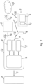
- FIG 1 A battery charging management system for a battery fleet 1 is shown schematically, which includes a number n of rechargeable, communication-capable battery units B 1 , ..., B n , where n is any natural number greater than one.
- Each battery unit B 1 , ..., B n has its own charging control unit 2.
- the battery charging management system includes a charging management base 3, which is set up to send charging setting information for the battery units B 1 , ..., B n , a number m of user terminals 4 1 , ..., 4 m , where m is an arbitrary natural number is greater than one, and a communication connection 5 for data transmission between the charging management base 3 on the one hand and the battery units B 1 , ..., B n on the other hand and between the user terminals 4 1 , ..., 4 m on the one hand and the charging management base 3 and / or the battery units B 1 , ..., B n on the other hand.
- the user terminals 4 1 , ..., 4 m are set up to send battery charging-related user specification information.
- the communication connection 5 is preferably, as in the example shown, designed to be wireless and, depending on the application, includes one or more communication channels and suitable communication components or communication interfaces in the user terminals 4 1 , ..., 4 m , the charging control units 2 and the charging management base 3 and, if necessary .external, ie outside of these system components mentioned. Examples in this regard are in the exemplary embodiment of Fig.
- the partial channel 5 32 and the are preferred second communication channel 5 2 is each implemented by a short-range communication connection, in particular a Bluetooth connection, while the sub-channel 5 31 and the first communication channel 5 1 are preferably each implemented by a long-range communication connection, in particular an Internet connection such as an LTE, WiFi, GSM, or LAN connection.
- a short-range communication connection in particular a Bluetooth connection
- the sub-channel 5 31 and the first communication channel 5 1 are preferably each implemented by a long-range communication connection, in particular an Internet connection such as an LTE, WiFi, GSM, or LAN connection.
- Fig. 2 shows an advantageous implementation of the system of Fig. 1 , with reference being made, as an example, to a j-th battery unit B j .
- the charging management base 3 is formed by a cloud backend 6 of a conventional type
- the user terminals 4 1 , ..., 4 m are part of a user front end 7 of a conventional type
- an i-th representative User terminal 4 i is shown in the form of a smartphone and the front end 7 can include further user terminals, for example a tablet 4S, a personal computer, ie PC, or the like.
- the front end 7 can be located spatially far away from the battery fleet 1, with the user on Location of the battery fleet 1, for example via a smartphone he is carrying, in Fig. 2 represented by a user terminal 4 p , can communicate directly with the respective battery unit B j or with the backend 6 or the intermediate station 10.
- the charging control unit is implemented, for example, by a microcontroller with implemented battery management functions.
- the charging setting information and/or the user specification information includes charging mode information regarding a plurality of different charging modes and can be supplied to the charging control unit 2 in the respective battery unit B 1 , ..., B n via the communication link 5.
- the charging control unit 2 is set up to carry out a charging process on a charger, such as an in Fig. 2 schematically shown charger 8, coupled battery unit B 1 , ..., B n to determine associated charging parameter setpoint information depending on the supplied charging setting information and / or user specification information and to transmit it to the charger 8.
- the charging parameter setpoint information can be stored in the charging control unit 2 depending on the charging mode information, ie charging mode specifications.
- the charging parameter setpoint information can in particular relate to the fact that the charger 8 carries out a charging process for the respective battery unit B 1 , ..., B n in accordance with a charging mode, as determined by the charging mode information contained in the supplied charging setting information and/or User preference information is included.
- the respective battery unit B 1 , ..., B n or, more precisely, its charging control unit 2 transmits the charging parameter setpoint information, ie the information about setpoint values of the charging parameters determining the charging process, to the charger 8 in a conventional manner via an associated communication connection 13 in a wired manner, e.g. via charging connections of the battery unit B 1 , ..., B n , or wirelessly.
- the charger 8 may be of any conventional type. If necessary, the communication connection 13 can also be used to transmit data from the charger 8 to the battery unit B 1 , ..., B n or the charging control unit 2.
- the user specification information can in particular also contain information that is useful for various aspects of target-time charging, in which the user can make specifications for the charging control unit 2 about at what time he should use which battery unit of the battery fleet 1 with which want to have charging status available.
- targets can contain, for example, information about a desired battery unit or a desired battery type, a desired time of use, a desired purpose, ie in which implement the battery unit is to be used, a desired battery voltage and/or a desired amount of energy.
- the charging setting information can also contain further specification information in addition to pure charging mode information, such as the specification of a charge state that is optimal for longer storage of the respective battery unit B 1 , ..., B n , for which a charge state that is approximately 80% of the full charge state is often selected , and/or the specification of a prioritized charging mode, such as the gentle charging mode that is optimal for the service life of the battery unit or the sustainable charging mode that is optimal from an environmental point of view.
- the charging control unit 2 determines the optimal charging process for the relevant battery unit B 1 , ..., B n taking these objectives into account.
- the charging control unit 2 can be set up, for example, based on the information supplied by the user about the desired operating time and that desired working device to determine how much charging the relevant battery unit B 1 , ..., B n requires and with which charging mode or which charging parameter setpoint information this charging can be carried out in the best possible way.
- Each of the charging control units 2 of the battery units B 1 , ..., B n has software or specifically firmware in corresponding implementations, which, in particular with regard to their versions, does not have to be the same in all battery units B 1 , ..., B n , That is, different battery units B 1 , ..., B n can have different firmware.
- the firmware can, for example, be uploaded, in particular updated, to the charging control unit 2 via the communication connection 5 from one of the user terminals 4 1 , ..., 4 m and/or from the charging management base 3.
- the charging control unit 2 can carry out or determine the assignment of charging parameter setpoints depending on the supplied charging mode information according to the firmware, that is, by transmitting a different firmware, in particular firmware version, from the charging management base 3 and/or the user terminal 41 , ..., 4 m can be influenced, in particular determined or programmed or determined, as the charging control unit 2 sets charging parameter setpoints depending on the charging mode information supplied.
- the respective battery unit B j contains, in addition to the charging control unit 2, a sensor system 12 for detecting charging parameters.
- the sensor system 12 can in particular include sensors for detecting the internal battery temperature and/or ambient temperature, voltage and/or current. For example, voltage and/or current can be measured using cables connected to individual series blocks in the battery unit B j or the battery pack, in particular with so-called balancer cables.
- a temperature sensor can be arranged in the battery unit B j, in particular between or under battery cells arranged therein and/or on the edge or on the inside of a housing of the battery unit B j . In this way, the temperature of the battery unit B j and the electrical voltage currently available from the battery unit B j or its state of charge can be recorded by means of the sensor system 12, whereby actual values of relevant, monitored charging parameters can also be recorded and monitored.
- the battery unit B j in this embodiment shown includes a communication interface 9 for connection to the communication connection 5 in order to transmit data such as recorded charging parameter data and/or battery status information to the user terminals 4 1 , ..., 4 m and/or to the intermediate station 10 and/or to transmit to the charging management base 3 and to receive the charging setting information or the user specification information.
- the battery unit B j in this embodiment shown has, for example, an optical display unit 11, for example with one or more light-emitting diodes, ie LEDs.
- an optical display unit 11 for example with one or more light-emitting diodes, ie LEDs.
- actual values of charging parameters such as a current charge level and/or charging current and/or a current charging power and/or battery temperature can be displayed or displayed on the battery unit B j by the battery unit B j and / or by the charging control unit 2 as required. be issued.
- the respective battery unit B 1 , ..., B n is used as a battery pack for supplying energy to hand-held work tools, in particular hand-held gardening, forestry, construction and/or tillage machines, or autonomous tillage machines, such as robotic lawnmowers, or electrically powered vehicles, such as e-bikes.
- hand-held work tools in particular hand-held gardening, forestry, construction and/or tillage machines, or autonomous tillage machines, such as robotic lawnmowers, or electrically powered vehicles, such as e-bikes.
- the respective battery pack can in particular comprise a plurality of battery cells which are arranged in series and/or parallel, electrically connected to one another, in the battery unit B 1 , ..., B n .
- the respective accumulator cell can be designed, for example, as a cylindrical cell, in particular as a so-called 18650 cell or 21700 cell, or as a pouch cell.
- the accumulator cell is preferably a lithium-ion cell, but other materials such as nickel-metal hydride or nickel-cadmium are also possible.
- the battery units B 1 , ..., B n can have different dimensions or dimensions, in particular length, width, height or mass. Furthermore, they can differ from each other in their maximum energy content.
- each battery unit B 1 , ..., B n can be assigned identifier information I 1 , ..., I n .
- the respective battery unit B 1 is via this identifier information I 1 , ..., I n , ..., B n clearly identifiable and distinguishable from all other battery units.
- the identifier information I 1 , ..., I n may be of any conventional type as is known to those skilled in the art, for example in the form of corresponding digital ID (identification) codes.
- the user terminals 4 1 , ..., 4 m and/or the charging management base 3 are, as also in Fig. 1 shown, in this case set up to use the identifier information I 1 , ..., I n one or more of the battery units B 1 , ..., B n into a number q of equal charging groups G 1 , ..., G q to group, with q as an arbitrarily predeterminable natural number.
- the battery units B 1 , B 2 and B 3 of a equal-charging group G 1 , the battery units B 4 , B 5 , B 6 and B 7 of a equal-charging group G 2 and the battery units B 8 to B n of a equal-charging group G q are exemplary assigned. However, the assignment can also be done differently, in particular having more or fewer battery units B 1 , ..., B n and/or synchronous charging groups G 1 , ..., G q . In general, the battery units B 1 , ..., B n of the battery fleet 1 can not be grouped at all or can be divided into just one or several equal charging groups G 1 , ..., G q .
- None, one, several or all battery units B 1 , ..., B n can be assigned to a synchronous charging group G 1 , ..., G q . Furthermore, it can be provided that a respective battery unit B 1 , ..., B n is assigned to none or only to a single or several of the equal charging groups G 1 , ..., G q at a respective time.
- a battery unit B 1 , ..., B n that is already assigned to a first equal-charging group G 1 , ..., G q is assigned to a second equal-charging group G 1 , ..., G q , it can, in particular, be selected by the user, additionally remain assigned to the first equal charging group G 1 , ..., G q or are instead removed from the first equal charging group G 1 , ..., G q .
- a respective equal-charging group G 1 , ..., G q can be created by a user without a battery unit B 1 , ..., B n already being assigned to this equal-charging group G 1 , ..., G q at the time of creation is or will be.
- the assignment of a battery unit B 1 , ..., B n can only take place at any time after a synchronous charging group G 1 , ..., G q has been created. This allows the simultaneous charging groups G 1 , ..., G q to be created and charging setting information and/or user specification information to be assigned to them without having to directly assign battery units B 1 , ..., B n to them.
- a synchronous charging group can, for example, include battery units of the same or different types that can or should be used for the same specific purpose or a same specific operational team, e.g. a mowing team for lawn mowing work, a gardening team for gardening/landscaping work or a forestry team for forestry work.
- the charging modes include several of a non-charging mode, a normal charging mode, a quick charging mode, a gentle charging mode and a sustainable charging mode, with the properties of these different charging modes already explained above.
- the charging management base 3 and/or the user terminals 4 1 , ..., 4 m and/or the charging control units 2 are set up to determine the charging mode information depending on prioritization information and/or usage history information. Additionally or alternatively, other or further charging modes may be included. For example, it is possible for additional charging modes to be defined by a user.
- Usage history information is collected and/or stored information about the use of the battery units B 1 , ..., B n in the past.
- the usage history information can be evaluated by the user terminals 4 1 , ..., 4 m and/or the charging management base 3.
- Usage history information can include, in particular, information about start times of use, end times of use, durations of use, amounts of energy or services delivered and/or temperatures that occur, in particular inside the battery units B 1 , ..., B n or in their surroundings.
- the usage history information can also include charging information, in particular battery charging parameters and/or Battery condition parameters include, such as charging power, charging current, charging voltage and end-of-charging voltage, internal battery temperature and/or ambient temperature, charging duration, charging start time and/or charging end time.
- the charging control unit 2 and/or the charging management base 3 and/or the user terminal 4 1 , ..., 4 m sets charging parameter setpoints using the prioritization information , which depend on or are combined from one or more charging modes or are given by a single prioritized charging mode or by a charging mode that is selected from several assigned charging modes as a currently optimal charging mode.
- the prioritization information makes it possible for charging mode information to be specified by the system automatically without any action or intervention by the user and/or taking into account or even exclusively through an input or selection by the user via a respective user terminal 4 1 , ..., 4 m .
- the usage history information includes information about a non-use period
- the prioritization information includes a prioritization of the gentle charging mode for the non-use period.
- the period of non-use can in particular be the period of time between two uses or until the next use of the battery unit B 1 , ..., B n , in particular to supply energy to a working device.
- the non-use period can be determined, for example, by the respective user terminal 4 1 , ..., 4 m and/or the charging management base 3, in particular by evaluating the usage history information.
- the non-use period can be assigned individually to a respective battery unit B 1 , ..., B n , in particular using the associated identifier information I 1 , ..., I n , in particular it does not have to be for all battery units B 1 , ..., B n be the same. Additionally or alternatively, a non-use period can also be assigned to a respective equal-charging group G 1 , ..., G q or to all battery units B 1 , ... , B n assigned to the relevant equal-charging group G 1 , ..., G q.
- the non-use period can, for example, be a period at night and/or on weekends.
- the usage history information includes information about an expected usage start time and the prioritization information includes a prioritization of the fast charging mode depending on the expected usage start time.
- the expected start time of use can be determined automatically by the system, in particular without any active intervention or intervention by a user. Priority is given to the quick charging mode in particular if rapid charging of the relevant battery unit is required in order to have sufficient energy available in the battery unit at the expected start of use.
- the user specification information includes information about a usage start time requested in particular by the user and/or by means of the respective user terminal 4 1 , ..., 4 m , and the user terminals 4 1 , ..., 4 m and/or the charging management base 3 and/or the charging control unit 2 are set up to determine the charging mode information and/or the charging parameter setpoint information depending on the requested start time of use. In this way, by notifying the system of the desired start time of use, the user can influence the determination of the charging mode information or the charging parameter setpoint information in such a way that the system can optimally adjust the charging process for a battery unit in question.
- a prioritization of the requested start of use time can be provided such that the battery unit is charged in quick charging mode until it has reached a charge level or charging level, ie charging capacity or energy content, required at the requested start of use time, and then in another charging mode, such as the non-charging mode or the gentle charging mode or the sustainable charging mode.
- the specification of the requested time of start of use can be accompanied by a specification of a requested charge level of the battery unit B 1 , ..., B n , which it should or must have at least at the time of start of use.
- the respective charging control unit 2 is for detecting at least one charging-relevant battery state parameter of its battery unit B 1 , ..., B n and for determining the charging parameter setpoint information for the relevant one Battery unit B 1 , ..., B n is set up depending on the recorded values of the at least one battery state parameter.
- Such battery state parameters or battery state information can in particular be one or more of the following battery state variables: a charge level, an aging state, the battery temperature, a, in particular maximum, end-of-charge voltage and a, in particular minimum, end-of-discharge voltage.
- the battery status information can be stored in or on or by the charging control unit 2.
- the charging control unit 2 can transmit this information via the communication connection 5 to the user terminals 4 1 , ..., 4 m and/or the charging management base 3, in particular in order to store and/or evaluate it there.
- the battery status information can be taken into account by the charging control unit 2 and/or the user terminals 4 1 , ..., 4 m and/or the charging management base 3 when determining the charging mode information and/or the charging parameter setpoint information, in particular, if necessary, additionally taking the prioritization information into account .
- the charging control unit 2 still determines the charging parameter setpoint information based on the charging mode information without taking into account the requested start of use time and possibly also without taking into account other recorded and / or stored battery status information in such a way that an otherwise Imminent overload and/or overheating and/or damage to the battery unit B 1 , ..., B n is avoided during or through the charging process.
- Taking the battery status information into account for the command of a respective battery charging process can in particular mean that different charging mode information or charging parameter setpoint information is specified for different battery units B 1 , ..., B n with different battery states, even if initially for these, ie without taking them into account Battery status, a same charging mode would be displayed. This can be the case, for example, if two battery units B 1 , ..., B n have different aging states.
- the battery status information when determining the charging mode information or the charging parameter setpoint information, is always given higher priority than usage history information and/or charging modes specified by the user and/or other specifications, such as a usage start time.
- the respective charging control unit 2 can, for example, store limit values for the recorded battery state variables and set the charging parameter setpoint information depending on a comparison of the recorded battery state information with the associated battery state limit values.
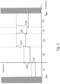
- the charging parameter setpoint information includes different charging current and/or charging voltage setpoint specifications for at least five different battery temperature ranges, as in the characteristic curve diagram of Fig. 3 shown for an example with seven different battery temperature ranges.
- a first charging mode is exemplified by a characteristic curve of the charging current as a function of the battery temperature, shown with solid lines, and a second charging mode is illustrated by a characteristic curve shown with dashed lines.
- the charging parameter setpoint information specifies the non-charging mode below a minimum temperature Tmin and above a maximum temperature Tmax.
- the charging parameter setpoint information specifies a successively higher charging current LI1, LI2, LI3 and generally also a successively higher charging voltage.
- the charging parameter setpoint information gives a charging current LI4, LI5 and in that is constant in the second charging mode and successively lower in the first charging mode As a rule, there is also a constant or gradually lower charging voltage.
- the charging current reduction in each of the two stages before the maximum temperature Tmax is smaller than the charging current increase in each of the two stages after the minimum temperature Tmin.
- the charging parameter setpoint information can also depend on further battery status information. In this regard, it is possible, for example, to depend on the aging condition of the battery unit B 1 , ..., B n . It is also possible for the charging parameter setpoint information to be determined by the charging control unit 2 in such a way that certain temperature ranges are avoided, ie the battery unit B 1 , ..., B n is then not charged. It is also possible to allow or set certain charging parameter setpoint information by the charging control unit 2 only in certain temperature ranges and not in certain other temperature ranges. Furthermore, it can be provided that certain charging parameter setpoint information is determined independently of temperature information or consistently across all temperature ranges.
- the number of temperature ranges and their division can be determined depending on the battery status information, in particular the aging status of the battery unit B 1 , ..., B n . It is also possible for the temperature ranges for the battery units B 1 , ..., B n to be the same or different.
- the temperature ranges are the same for all battery units B 1 , ..., B n that are assigned to a specific equal-charging group, for example the equal-charging group G 1 , and for all battery units B 1 , ..., B n , which are assigned to another equal-charging group, for example the equal-charging group G 2 , are also the same, but different from those of the battery units B 1 , ..., B n belonging to the first equal-charging group G 1 .
- Illustrated battery charging management system enables the implementation of a battery charging management method for the battery fleet 1 with the battery units B 1 , ..., B n , in which the charging setting information for the battery units B 1 , ..., B n is transmitted from the charging management base 3, the battery units B 1 , ..., B n are equipped with the respective charging control unit 2, the user terminals 4 1 , ..., 4 m are provided, from which battery charging-related user specification information is transmitted, the communication connection 5 for data transmission between the charging management base 3 on the one hand and the battery units B 1 , ..., B n on the other hand and between the user terminals 4 1 , ..
- the charging setting information and/or the user specification information includes the charging mode information regarding the different charging modes, the charging setting information from the charging management base 3 and/or the user specification information from the user terminals 4 1 , ..., 4 m via the communication link 5 of the charging control unit) in the respective battery unit B 1 , ..., B n are supplied and to carry out a charging process for the respective battery unit B 1 , ..., B n coupled to the charger 8 from its charging control unit 2 the associated charging parameter setpoint information depending on the charging setting information and/or user specification information supplied and transmitted to the charger.
- Fig. 4 shows a flowchart illustrating a specific part of the battery management method in one embodiment.
- a set of charging mode information is available to the charging control unit 2 in a step 40.
- This charging mode information can be derived in particular from the previous charging setting information and/or user specification information and possibly previously available battery status information.
- the respective charging control unit 2 queries the currently available battery status parameters, such as the temperature of the battery unit B 1 , ..., B n .
- the charging control unit 2 queries the user specification information, such as a requested usage start time.
- the charging control unit 2 sets a current charging mode in a step 46.
- the charging mode determined from the user data in step 46 is linked or compared with the battery status parameters queried in step 42.
- the linking or comparison of this data takes into account the prioritization of the existing charging mode information and results in corresponding prioritization information.
- This prioritization information includes information as to whether the battery status parameters allow the selected charging mode or not. If this is not the case, the charging mode is redetermined or set in a step 50 based on the battery condition parameters and the preselected charging mode. Otherwise, the one preselected by the user or by the system
- the previously prioritized charging mode is maintained by the charging control unit 2, ie the battery state parameters do not change the predetermined charging mode in this case.
- the charging process is then carried out with the current charging mode determined in this way in a step 52.
- a step 54 it is checked whether new or changed charging setting information and/or user specification information, in particular charging mode information, and/or battery status information, is available. If this is not the case, the previously executed loading mode is retained. If, on the other hand, there is changed or new information, the process returns to step 40 and the charging mode or the charging parameter setpoint information is updated based on this new or changed information.
- the invention provides a battery charge management system and a battery charge management method with which the battery units of a battery fleet can be managed in a very advantageous manner with regard to their charging states, their charging procedures and their assignment to operational teams.
Abstract
1. Batterielademanagementsystem und Batterielademanagementverfahren.2.1. Die Erfindung bezieht sich auf ein Batterielademanagementsystem für eine Batterieflotte (1) mit einer Mehrzahl von wiederaufladbaren, kommunikationsfähigen Batterieeinheiten (B<sub>1</sub>, ..., B<sub>n</sub>) und auf ein entsprechendes Batterielademanagementverfahren.2.2. Erfindungsgemäß umfasst das System eine Lademanagementbasis (3), die zum Senden von Ladeeinstellinformationen für die Batterieeinheiten eingerichtet ist, eine Mehrzahl von Nutzerendgeräten (4<sub>1</sub>, ..., 4<sub>m</sub>), die zum Senden von batterieladebezogenen Nutzervorgabeinformationen eingerichtet sind, je eine Ladesteuereinheit (2) in jeder der Batterieeinheiten und eine Kommunikationsverbindung (5) zur Datenübertragung zwischen der Lademanagementbasis (3) einerseits und den Batterieeinheiten andererseits sowie zwischen den Nutzerendgeräten einerseits und der Lademanagementbasis und/oder den Batterieeinheiten andererseits. Die Ladeeinstellinformationen und/oder die Nutzervorgabeinformationen umfassen Lademodusinformationen bezüglich einer Mehrzahl unterschiedlicher Lademodi für die Batterieeinheiten. Die Ladeeinstellinformationen und/oder die Nutzervorgabeinformationen sind der Ladesteuereinheit in der jeweiligen Batterieeinheit über die Kommunikationsverbindung zuführbar. Die jeweilige Ladesteuereinheit ist dafür eingerichtet, zur Durchführung eines Ladevorgangs ihrer an ein Ladegerät angekoppelten Batterieeinheit zugehörige Ladeparameter-Sollwertinformationen in Abhängigkeit von den zugeführten Ladeeinstellinformationen und/oder Nutzervorgabeinformationen festzulegen und an das Ladegerät zu übermitteln.2.3. Verwendung z.B. für Akkupacks zur Energieversorgung von handgeführten Garten-, Forst-, Bau- und/oder Bodenbearbeitungsgeräten.1. Battery charge management system and battery charge management procedures.2.1. The invention relates to a battery charging management system for a battery fleet (1) with a plurality of rechargeable, communication-capable battery units (B<sub>1</sub>, ..., B<sub>n</sub>) and to a corresponding one Battery charge management procedures.2.2. According to the invention, the system comprises a charging management base (3), which is set up to send charging setting information for the battery units, a plurality of user terminals (4<sub>1</sub>, ..., 4<sub>m</sub>) , which are set up to send battery charging-related user specification information, a charging control unit (2) in each of the battery units and a communication connection (5) for data transmission between the charging management base (3) on the one hand and the battery units on the other hand and between the user terminals on the one hand and the charging management base and / or the battery units on the other hand. The charging setting information and/or the user preference information includes charging mode information regarding a plurality of different charging modes for the battery units. The charging setting information and/or the user specification information can be supplied to the charging control unit in the respective battery unit via the communication connection. The respective charging control unit is set up to carry out a charging process for its battery unit coupled to a charger to determine associated charging parameter setpoint information depending on the supplied charging setting information and / or user specification information and to transmit it to the charger.2.3. Use, for example, for battery packs to supply energy to hand-held gardening, forestry, construction and/or soil cultivation equipment.
Description
Die Erfindung bezieht sich auf ein Batterielademanagementsystem für eine Batterieflotte mit einer Mehrzahl von wiederaufladbaren, kommunikationsfähigen Batterieeinheiten und auf ein entsprechendes Batterielademanagementverfahren, wobei das Batterielademanagementsystem eine Lademanagementbasis umfasst, die zum Senden von Ladeeinstellinformationen für die Batterieeinheiten eingerichtet ist.The invention relates to a battery charge management system for a battery fleet with a plurality of rechargeable, communication-capable battery units and to a corresponding battery charge management method, wherein the battery charge management system comprises a charge management base that is set up to send charge setting information for the battery units.
Systeme und Verfahren dieser Art dienen dem Lademanagement für die elektrisch wiederaufladbaren Batterieeinheiten, was insbesondere entsprechende Maßnahmen zur Einstellung, Steuerung und Durchführung elektrischer Ladevorgänge für die Batterieeinheiten umfasst. Die Batterieeinheiten sind zu der Batterieflotte zusammengefasst, d.h. zu einer Gesamtheit, aus der sich ein oder mehrere Nutzer bedienen können, um sich eine jeweilige Batterieeinheit für einen beabsichtigten Einsatzzweck zu beschaffen. Die Batterieeinheiten können gleicher oder unterschiedlicher Bauart bzw. gleichen oder unterschiedlichen Typs sein und beispielsweise als sogenannte Akkupacks realisiert sein, wie sie üblicherweise zur Energieversorgung von diversen elektrisch angetriebenen Geräten benutzt werden. Bei diesen Geräten kann es sich z.B. um handgeführte Arbeitsgeräte, wie handgetragene oder bodengetragene Arbeitsgeräte bzw. Bearbeitungsgeräte im Bau- und Heimwerkerbereich, im Gartenbau und in der Forstwirtschaft handeln.Systems and methods of this type serve for charging management for the electrically rechargeable battery units, which in particular includes appropriate measures for setting, controlling and carrying out electrical charging processes for the battery units. The battery units are combined into the battery fleet, i.e. into an entirety from which one or more users can choose to obtain a respective battery unit for an intended purpose. The battery units can be of the same or different design or of the same or different type and can be implemented, for example, as so-called battery packs, as are usually used to supply energy to various electrically powered devices. These devices can be, for example, hand-held work tools, such as hand-carried or ground-carried work tools or processing devices in the construction and do-it-yourself sector, in horticulture and in forestry.
Es sind bereits diverse Batterielademanagementsysteme dieser und ähnlicher Art und von diesen durchführbare Batterielademanagementverfahren gebräuchlich, wobei die Lademanagementmaßnahmen von Typ Art und Einsatzbedarf der Batterieeinheiten und weiteren Parametern abhängen können, die Einfluss auf den Ladezustand und die Durchführung der Ladevorgänge haben. Ein solcher, häufig berücksichtigter Einflussparameter ist die Batterietemperatur, siehe z.B. die Patentschrift
Die Offenlegungsschrift
Die Patentschrift
Die Patentschrift
Die Offenlegungsschrift
Der Erfindung liegt als technisches Problem die Bereitstellung eines Batterielademanagementsystems und eines Batterielademanagementverfahrens der eingangs genannten Art zugrunde, die gegenüber dem oben erwähnten Stand der Technik weitergehende Verbesserungen des Batterielademanagements bieten.The invention is based on the technical problem of providing a battery charging management system and a battery charging management method of the type mentioned at the outset, which offer further improvements in battery charging management compared to the prior art mentioned above.
Die Erfindung löst dieses Problem durch die Bereitstellung eines Batterielademanagementsystems mit den Merkmalen des Anspruchs 1 und eines Batterielademanagementverfahrens mit den Merkmalen des Anspruchs 11. Vorteilhafte Weiterbildungen der Erfindung sind in den Unteransprüchen angegeben, deren Wortlaut hiermit durch Verweis zum Bestandteil der Beschreibung gemacht wird. Dies schließt insbesondere auch alle Ausführungsformen der Erfindung ein, die sich aus den Merkmalskombinationen ergeben, die durch die Rückbezüge in den Unteransprüchen definiert sind.The invention solves this problem by providing a battery charging management system with the features of claim 1 and a battery charging management method with the features of claim 11. Advantageous developments of the invention are specified in the subclaims, the wording of which is hereby incorporated by reference into the description. This includes in particular all embodiments of the invention that result from the combinations of features that are defined by the references in the subclaims.
Das erfindungsgemäße Batterielademanagementsystem umfasst eine Lademanagementbasis, die zum Senden von Ladeeinstellinformationen für die Batterieeinheiten eingerichtet ist, eine Mehrzahl von Nutzerendgeräten, die zum Senden von batterieladebezogenen Nutzervorgabeinformationen eingerichtet sind, je eine Ladesteuereinheit in jeder der Batterieeinheiten und eine Kommunikationsverbindung zur Datenübertragung zwischen der Lademanagementbasis einerseits und den Batterieeinheiten andererseits und zwischen den Nutzerendgeräten einerseits und der Lademanagementbasis und/oder den Batterieeinheiten andererseits. Es versteht sich, dass die Lademanagementbasis und/oder die Nutzerendgeräte je nach Bedarf und Anwendungsfall weitere implementierte Funktionalitäten aufweisen können, insbesondere auch solche, wie sie vorliegend an anderer Stelle genannt oder dem Fachmann von herkömmlichen Komponenten dieser Art an sich bekannt sind.The battery charging management system according to the invention includes a charging management base that is set up to send charging setting information for the battery units, a plurality of user terminals that are set up to sending battery charging-related user specification information, a charging control unit in each of the battery units and a communication connection to the Data transmission between the charging management base on the one hand and the battery units on the other hand and between the user terminals on the one hand and the charging management base and / or the battery units on the other hand. It is understood that the charging management base and/or the user terminals can have further implemented functionalities depending on the needs and application, in particular those such as those mentioned elsewhere or known to those skilled in the art from conventional components of this type.
Die Ladeeinstellinformationen und/oder die Nutzervorgabeinformationen umfassen Lademodusinformationen bezüglich einer Mehrzahl unterschiedlicher Lademodi für die Batterieeinheiten. Über die Kommunikationsverbindung sind der Ladesteuereinheit in der jeweiligen Batterieeinheit die Ladeeinstellinformationen von der Lademanagementbasis und/oder die Nutzervorgabeinformationen von den Nutzerendgeräten zuführbar. Je nach Systemrealisierung bestehen die Ladeeinstellinformationen bzw. die Nutzervorgabeinformationen einzig aus den Lademodusinformationen oder enthalten zusätzliche batterieladebezogene Informationen. In jedem Fall erhält die jeweilige Ladesteuereinheit dadurch Kenntnis von einem gewünschten bzw. angeforderten Lademodus, ggf. ergänzt durch weitere laderelevante Informationen. Bevorzugt werden die Ladeeinstellinformationen in der Lademanagementbasis vorgehalten, indem sie dort geeignet gespeichert sind. Die Nutzervorgabeinformationen können im jeweiligen Nutzerendgerät vorgehalten, d.h. abgespeichert, sein und vom Benutzer zum Senden an die Lademanagementbasis und/oder die jeweilige Ladesteuereinheit ausgewählt werden, und/oder sie können vom Benutzer zum Senden an die Lademanagementbasis und/oder die jeweilige Ladesteuereinheit am Nutzerendgerät eingegeben werden.The charging setting information and/or the user preference information includes charging mode information regarding a plurality of different charging modes for the battery units. The charging control unit in the respective battery unit can be supplied with the charging setting information from the charging management base and/or the user specification information from the user terminals via the communication connection. Depending on the system implementation, the charging setting information or the user default information consists solely of the charging mode information or contains additional battery charging-related information. In any case, the respective charging control unit thereby receives knowledge of a desired or requested charging mode, possibly supplemented by further charging-relevant information. The charging setting information is preferably kept in the charging management base by being suitably stored there. The user specification information can be kept, i.e. stored, in the respective user terminal and selected by the user for sending to the charging management base and/or the respective charging control unit, and/or it can be entered by the user on the user terminal for sending to the charging management base and/or the respective charging control unit become.
Die jeweilige Ladesteuereinheit ist dafür eingerichtet, zur Durchführung eines Ladevorgangs ihrer an ein Ladegerät angekoppelten Batterieeinheit zugehörige Ladeparameter-Sollwertinformationen in Abhängigkeit von den zugeführten Ladeeinstellinformationen und/oder Nutzervorgabeinformationen und damit insbesondere in Abhängigkeit von den darin enthaltenen Lademodusinformationen festzulegen und an das Ladegerät zu übermitteln. Die für das System benötigte System intelligenz kann daher großteils in den Ladesteuereinheiten und folglich in den Batterieeinheiten implementiert sein. Damit können sowohl das oder die Ladegeräte als auch die Lademanagementbasis von entsprechenden Systemintelligenzimplementierungen entlastet und auf die Erfüllung anderer Funktionen, wie die für das Lademanagement der Flotte benötigten Kommunikationsfunktionen, hin optimiert bzw. auf diese fokussiert werden.The respective charging control unit is set up to carry out a charging process of its battery unit coupled to a charger to determine the associated charging parameter setpoint information depending on the supplied charging setting information and / or user specification information and thus in particular depending on the charging mode information contained therein and to transmit it to the charger. The system intelligence required for the system can therefore be largely implemented in the charging control units and consequently in the battery units. This means that both the charger(s) and the charging management base can be used be relieved of corresponding system intelligence implementations and optimized or focused on the fulfillment of other functions, such as the communication functions required for fleet charging management.
Das derart ausgelegte, erfindungsgemäße Batterielademanagementsystem ermöglicht es in einfacher und optimaler Weise, Ladevorgänge für die Batterieeinheiten der Flotte zu ermitteln und durchzuführen. Der Nutzer kann bei Bedarf über sein Nutzerendgerät einen gewünschten Lademodus und optional weitere Ladevorgaben für eine ausgewählte oder eine beliebige der Batterieeinheiten, z.B. auch Informationen über eine beabsichtigte Einsatzzeit und/oder einen beabsichtigten Einsatzzweck, als Nutzervorgabeinformationen vorgeben bzw. an die Lademanagementbasis und/oder die jeweilige Ladesteuereinheit übermitteln. Die jeweilige Ladesteuereinheit in der betreffenden Batterieeinheit ist durch die in ihr implementierte Ladeintelligenz in der Lage zu ermitteln, ob der vom Benutzer gewünschte Lademodus auch unter Berücksichtigung anderweitiger Gegebenheiten momentan optimal ist oder alternativ einem anderen Lademodus der Vorzug zu geben ist, z.B. unter Berücksichtigung einer ermittelten voraussichtlichen Ladedauer und/oder eines erfassten Lade- und/oder Alterungszustands der Batterieeinheit und/oder eines mitgeteilten Einsatzzeitpunktes und/oder Einsatzzweckes der Batterieeinheit und/oder einer ermittelten bzw. erfassten Batterietemperatur und/oder unter Berücksichtigung von Nachhaltigkeitsaspekten und/oder Ladestromkostenaspekten. Die Ladesteuereinheiten können bei Bedarf auch selbsttätig, d.h. ohne aktuelle Nutzeranforderung, Ladevorgänge für ihre Batterieeinheiten initiieren, um die gesamte Batterieflotte optimal einsatzbereit zu halten. In jedem Fall leitet die jeweilige Ladesteuereinheit dann das den Ladestrom bzw. die Ladespannung bereitstellende Ladegerät zur Durchführung des als optimal ermittelten Ladevorgangs an, indem es die entsprechenden Ladeparameter-Sollwertinformationen an das Ladegerät übermittelt.The battery charging management system according to the invention designed in this way makes it possible to determine and carry out charging processes for the battery units in the fleet in a simple and optimal manner. If necessary, the user can use his user terminal to specify a desired charging mode and optionally further charging specifications for a selected or any of the battery units, e.g. also information about an intended period of use and/or an intended purpose of use, as user specification information or to the charging management base and/or the transmit the respective charging control unit. Due to the charging intelligence implemented in it, the respective charging control unit in the relevant battery unit is able to determine whether the charging mode desired by the user is currently optimal, even taking other circumstances into account, or alternatively, preference should be given to another charging mode, e.g. taking into account a determined one expected charging time and/or a recorded charging and/or aging state of the battery unit and/or a reported time of use and/or purpose of use of the battery unit and/or a determined or recorded battery temperature and/or taking into account sustainability aspects and/or charging current cost aspects. If necessary, the charging control units can also initiate charging processes for their battery units automatically, i.e. without a current user request, in order to keep the entire battery fleet optimally ready for use. In any case, the respective charging control unit then instructs the charger providing the charging current or charging voltage to carry out the charging process determined to be optimal by transmitting the corresponding charging parameter setpoint information to the charger.
Das Festlegen der Ladeparameter-Sollwerte durch die Ladesteuereinheit in jeder Batterieeinheit und das Übermitteln zum Ladegerät ermöglicht ein Kontrollieren des Ladevorgangs jeder Batterieeinheit unabhängig von dem jeweils verwendeten Ladegerät. Dies kann auch die Benutzung unterschiedlicher Typen von Ladegeräten ermöglichen, mit denen die Batterieeinheiten elektrisch verbunden werden können. Es kann bei Bedarf auch vorgesehen sein, dass eine jeweilige Batterieeinheit durch mehrere sequentielle Ladevorgänge mit gleichen oder verschiedenen Ladeparametern unter Verwendung des gleichen oder von verschiedenenen Ladegeräten geladen wird. Die Kommunikationsverbindung ermöglicht ein Übertragen der Ladeeinstellinformationen, einschließlich der Lademodusinformationen, und der Nutzervorgabeinformationen sowie je nach Bedarf von für Ladevorgänge relevanten Batteriezustandsdaten aller Art, so dass die betreffenden Informationen bzw. Daten in einer jeweils gewünschten Weise an einem gewünschten Speicherort gespeichert und/oder durch eine hierfür vorgesehene Auswerteeinheit z.B. in der jeweiligen Ladesteuereinheit oder dem jeweiligen Nutzerendgerät oder der Lademanagementbasis ausgewertet bzw. weiterverarbeitet werden können.Setting the charging parameter setpoints by the charging control unit in each battery unit and transmitting them to the charger enables the charging process of each battery unit to be controlled independently of the charger used. This may also enable the use of different types of chargers to which the battery units can be electrically connected. It can if necessary It can also be provided that a respective battery unit is charged by several sequential charging processes with the same or different charging parameters using the same or different chargers. The communication connection enables the charging setting information, including the charging mode information, and the user specification information, as well as, as required, all types of battery status data relevant to charging processes to be transmitted, so that the relevant information or data is stored in a desired manner at a desired storage location and / or by a The evaluation unit provided for this purpose can be evaluated or further processed, for example in the respective charging control unit or the respective user terminal or the charging management base.
Die Kommunikationsverbindung ist vorzugsweise eine herkömmliche drahtlose Kommunikationsverbindung und kann insbesondere eine Bluetooth-, LTE-, WiFi-, Zigbee-, GSM-, LAN- oder ähnliche Verbindung sein. Sie kann die kommunikative Verbindung zwischen jeweiliger Batterieeinheit, Lademanagementbasis und jeweiligem Nutzerendgerät direkt ohne Zwischenschaltung anderweitiger Kommunikationskomponenten oder indirekt bereitstellen, d.h. unter Zwischenschaltung einer oder mehrerer anderer Kommunikationskomponenten, wie eines Gateways oder dgl. Dabei kann die Kommunikationsverbindung einteilig oder mehrteilig, insbesondere bestehend aus mehreren verschiedenen Kommunikationskanälen, ausgeführt sein. In letzterem Fall kann sie beispielsweise einen oder mehrere Bluetooth-Kanäle und einen oder mehrere Internetverbindungkanäle wie LTE- oder WiFi-Kanäle beinhalten, einschließlich etwaiger entsprechender Transfereinheiten wie Gateways, die zwischen den verschiedenen Kanälen vermitteln. Die Datenübertragung kann in einer beliebigen herkömmlichen Weise erfolgen, z.B. sequenziell oder als Datenpakete und/oder zyklisch. Daten können an eine oder mehrere der Batterieeinheiten gleichzeitig oder aufeinanderfolgend übertragen werden.The communication connection is preferably a conventional wireless communication connection and can in particular be a Bluetooth, LTE, WiFi, Zigbee, GSM, LAN or similar connection. It can provide the communicative connection between the respective battery unit, charging management base and respective user terminal directly without the interposition of other communication components or indirectly, i.e. with the interposition of one or more other communication components, such as a gateway or the like. The communication connection can be in one piece or in several parts, in particular consisting of several different ones communication channels. In the latter case, it may include, for example, one or more Bluetooth channels and one or more Internet connection channels such as LTE or WiFi channels, including any corresponding transfer units such as gateways that mediate between the different channels. The data transmission can take place in any conventional manner, for example sequentially or as data packets and/or cyclically. Data may be transmitted to one or more of the battery units simultaneously or sequentially.
Die Lademanagementbasis kann z.B. einen Server, eine Datenbank, eine Cloud-Basis oder dgl. beinhalten.The charging management base can include, for example, a server, a database, a cloud base or the like.
Das jeweilige Nutzerendgerät kann z.B. einen Computer oder ein mobiles Gerät wie ein Smartphone, ein Tablet, eine Smartwatch oder dgl. beinhalten.The respective user device can, for example, contain a computer or a mobile device such as a smartphone, a tablet, a smartwatch or the like.
In einer Weiterbildung der Erfindung sind die Batterieeinheiten als Akkupacks zur Energieversorgung von handgeführten Arbeitsgeräten, insbesondere von handgeführten Garten-, Forst-, Bau- und/oder Bodenbearbeitungsgeräten, ausgeführt. Dies können z.B. Rasenmäher, Hochentaster, Heckenschere, Motorsäge, Trennschleifer usw. sein. Alternativ können die Batterieeinheiten zur Energieversorgung anderer Geräte bzw. Maschinen dienen, z.B. für autonome Bodenbearbeitungsgeräte, wie Mähroboter, oder Elektrofahrzeuge, wie E-Bikes.In a further development of the invention, the battery units are designed as battery packs for supplying energy to hand-held work tools, in particular hand-held gardening, forestry, construction and/or soil cultivation tools. These can be, for example, lawn mowers, pole pruners, hedge trimmers, chainsaws, cut-off machines, etc. Alternatively, the battery units can be used to supply energy to other devices or machines, e.g. for autonomous soil cultivation devices, such as robotic lawnmowers, or electric vehicles, such as e-bikes.
In einer Weiterbildung der Erfindung ist jeder Batterieeinheit eine Identifikatorinformation zuweisbar, und die Nutzerendgeräte und/oder die Lademanagementbasis sind/ist zur Gruppierung der Batterieeinheiten in eine oder mehrere Gleichladegruppen unter Verwendung der Identifikatorinformationen eingerichtet. Unter einer Gleichladegruppe ist hierbei vorliegend eine Gruppe zu verstehen, die eine oder mehrere der Batterieeinheiten umfasst, die in Bezug auf das Batterielademanagementsystem unter sich gleichartig bzw. austauschbar für einen bestimmten Einsatzzweck und/oder zur Energieversorgung eines zugeordneten Geräte- bzw. Maschinenteams oder Geräte- bzw. Maschinenparks verwendbar und hierfür aufladbar sind. Dies stellt eine vorteilhafte Aufteilbarkeit der Batterieflotte in Gruppen von Batterieeinheiten zur Verfügung, von denen jede z.B. einem bestimmten Einsatzteam zugeordnet sein kann, wie einem Forstteam für Waldarbeiten und/oder einem Mähteam für Mäharbeiten etc. Es ist dabei auch möglich, eine entsprechende Batterieeinheit mehreren verschiedenen Einsatzteams zuzuordnen. Alternativ kann auf eine solche Gruppenaufteilbarkeit der Batterieflotte verzichtet werden.In a further development of the invention, each battery unit can be assigned identifier information, and the user terminals and/or the charging management base are/is set up to group the battery units into one or more equal charging groups using the identifier information. In this case, a common charging group is to be understood as meaning a group that includes one or more of the battery units that are similar or interchangeable with respect to the battery charging management system for a specific purpose and/or for supplying energy to an assigned device or machine team or device team. or machine parks can be used and can be charged for this purpose. This provides an advantageous ability to divide the battery fleet into groups of battery units, each of which can, for example, be assigned to a specific operational team, such as a forestry team for forestry work and/or a mowing team for mowing work, etc. It is also possible to have a corresponding battery unit in several different ones Assign operational teams. Alternatively, the battery fleet cannot be divided into groups in this way.
In einer Weiterbildung der Erfindung umfassen die Lademodi mehrere von einem Nicht-Lademodus, einem Normal-Lademodus, einem Schnell-Lademodus, einem Schonend-Lademodus und einem Nachhaltig-Lademodus, und die Lademanagementbasis und/oder die Nutzerendgeräte und/oder die Ladesteuereinheiten ist/sind dafür eingerichtet, die Lademodusinformationen und/oder die Ladeparameter-Sollwertinformationen in Abhängigkeit von Priorisierungsinformationen und/oder Nutzungshistorieinformationen festzulegen.In a further development of the invention, the charging modes include several of a non-charging mode, a normal charging mode, a quick charging mode, a gentle charging mode and a sustainable charging mode, and the charging management base and/or the user terminals and/or the charging control units is/ are set up to set the charging mode information and/or the charging parameter setpoint information depending on prioritization information and/or usage history information.
Als Nicht-Lademodus wird vorliegend verstanden, dass die Batterieeinheit im zugehörigen Zeitraum nicht geladen wird. Der Normal-Lademodus stellt eine Referenz dar, auf den sich die anderen Lademodi vergeichend beziehen. Durch den Schonend-Lademodus kann die Batterieeinheit im Vergleich zum Normal-Lademodus über einen längeren zur Verfügung stehenden Zeitraum hinweg sehr schonend geladen werden, was einer hohen Lebensdauer der Batterieeinheit zugute kommt. Durch den Schnell-Lademodus kann sichergestellt werden, dass die Batterieeinheit in relativ kurzer Zeit vollgeladen oder zumindest auf einen erforderlichen Ladestand gebracht werden kann, wenn sie demnächst genutzt werden soll. Der Nachhaltig-Lademodus ermöglicht ein hinsichtlich Nachhaltigkeitsaspekten optimiertes Aufladen der Batterieeinheiten.In the present case, non-charging mode is understood to mean that the battery unit is not charged during the associated period of time. The normal charging mode represents a reference to which the other charging modes refer comparatively. Thanks to the gentle charging mode, the battery unit can be charged very gently over a longer period of time compared to the normal charging mode, which benefits the battery unit's long service life. The quick charging mode can ensure that the battery unit can be fully charged or at least brought to the required charge level in a relatively short time if it is to be used soon. The sustainable charging mode enables the battery units to be charged in an optimized way with regard to sustainability aspects.
Die Priorisierungsinformationen können z.B. Batterielebensdauer-, Einsatzzeit-, Ladekosten- und/oder Nachhaltigkeitsaspekte berücksichtigen. Die Nutzungshistorieinformationen können z.B. typische Einsatzzeiträume bzw. Nichtbenutzungszeiträume der Batterieeinheiten berücksichtigen, wie sie vom System anhand entsprechender Daten über die Nutzung der Batterieeinheit in der Vergangenheit ermittelt werden können. Diese Weiterbildung trägt daher vorteilhaft dazu bei, den für die jeweilige Situation bestmöglichen Ladevorgang aufzufinden bzw. festzulegen. Alternativ können z.B. Algorithmen ohne Priorisierungs- und Nutzungshistorieinformationen zur Festlegung des jeweils aktuellen Ladevorgangs benutzt werden, wenn dies für den betreffenden Anwendungsfall ausreicht.The prioritization information can, for example, take into account battery life, usage time, charging costs and/or sustainability aspects. The usage history information can, for example, take into account typical periods of use or periods of non-use of the battery units, as can be determined by the system based on corresponding data about the use of the battery unit in the past. This further development therefore advantageously contributes to finding or determining the best possible charging process for the respective situation. Alternatively, for example, algorithms without prioritization and usage history information can be used to determine the current charging process if this is sufficient for the relevant application.
In einer Ausgestaltung der Erfindung umfassen die Nutzungshistorieinformationen Informationen über einen Nichtnutzungszeitraum, und die Priorisierungsinformationen umfassen eine Priorisierung des Schonend-Lademodus für den Nichtnutzungszeitraum. Dadurch ist das System vorteilhaft in der Lage, selbsttätig ein schonendes, die Lebensdauer der Batterieeinheit verlängerndes Laden der Batterieeinheit in entsprechenden Zeiträumen voreinzustellen. Alternativ kann eine Priorisierung des Schonend-Lademodus entfallen oder von anderen Bedingungen abhängig gemacht werden.In one embodiment of the invention, the usage history information includes information about a non-use period, and the prioritization information includes a prioritization of the gentle charging mode for the non-use period. As a result, the system is advantageously able to automatically preset gentle charging of the battery unit in appropriate periods of time, which extends the service life of the battery unit. Alternatively, prioritization of the gentle charging mode can be omitted or made dependent on other conditions.
In einer Ausgestaltung der Erfindung umfassen die Nutzungshistorieinformationen Informationen über einen erwarteten Nutzungsstartzeitpunkt, und die Priorisierungsinformationen umfassen eine Priorisierung des Schnell-Lademodus in Abhängigkeit von dem erwarteten Nutzungsstartzeitpunkt. Dadurch ist das System vorteilhaft in der Lage, selbsttätig ein schnelles Laden der Batterieeinheit voreinzustellen, damit diese zum erwarteten Zeitpunkt ihres Einsatzes ausreichend geladen ist. Alternativ kann eine Priorisierung des Schnell-Lademodus entfallen oder von anderen Bedingungen abhängig gemacht werden. Die Priorisierungsinformationen können in einer entsprechenden Realisierung allgemein eine Priorisierung eines abhängig vom erwarteten Nutzungsstartzeitpunkt und dem aktuellen Zustand der Batterieeinheit als bestpassend ermittelten Lademodus beinhalten, um einerseits die Batterieeinheit möglichst schonend zu laden und andererseits zum Einsatzzeitpunkt genügend Batteriekapazität für den bevorstehenden Nutzungsvorgang verfügbar zu haben.In one embodiment of the invention, the usage history information includes information about an expected usage start time and the prioritization information include prioritization of the fast charging mode depending on the expected start time of use. As a result, the system is advantageously able to automatically preset rapid charging of the battery unit so that it is sufficiently charged at the expected time of use. Alternatively, prioritization of the fast charging mode can be omitted or made dependent on other conditions. In a corresponding implementation, the prioritization information can generally include a prioritization of a charging mode that is determined to be the most suitable depending on the expected start time of use and the current state of the battery unit in order, on the one hand, to charge the battery unit as gently as possible and, on the other hand, to have sufficient battery capacity available at the time of use for the upcoming usage process.
In einer Ausgestaltung der Erfindung umfassen die Nutzervorgabeinformationen Informationen über einen angeforderten Nutzungsstartzeitpunkt, und die Nutzerendgeräte und/oder die Lademanagementbasis und/oder die Ladesteuereinheiten ist/sind dafür eingerichtet, die Lademodusinformationen und/oder die Ladeparameter-Sollwertinformationen in Abhängigkeit vom angeforderten Nutzungsstartzeitpunkt festzulegen. Diese Maßnahme ermöglicht vorteilhaft ein optimales Ziel-Zeit-Laden, bei dem das System, insbesondere die jeweilige Ladesteuereinheit, unter Kenntnis des Einsatzzeitpunktes und des Zustands ihrer Batterieeinheit einen für die Batterieeinheit optimalen Ladevorgang festlegen und initiieren kann, so dass diese einerseits zum gewünschten Zeitpunkt den erforderlichen Ladezustand erreicht hat und andererseits das Aufladen unter optimierender Berücksichtigung der laderelevanten Parameter erfolgt. Alternativ kann das System in vereinfachten Ausführungen ohne diese einsatzzeitpunktabhängige Ladevorgangsoptimierung auskommen.In one embodiment of the invention, the user specification information includes information about a requested usage start time, and the user terminals and/or the charging management base and/or the charging control units is/are set up to set the charging mode information and/or the charging parameter setpoint information depending on the requested usage start time. This measure advantageously enables optimal target time charging, in which the system, in particular the respective charging control unit, can determine and initiate a charging process that is optimal for the battery unit, knowing the time of use and the state of its battery unit, so that on the one hand it can do so at the desired time has reached the required state of charge and, on the other hand, charging takes place with optimal consideration of the charging-relevant parameters. Alternatively, in simplified versions, the system can manage without this charging process optimization depending on the time of use.
In einer Weiterbildung der Erfindung ist die jeweilige Ladesteuereinheit zur Erfassung wenigstens eines laderelevanten Batteriezustandsparameters ihrer Batterieeinheit und zur Festlegung der Ladeparameter-Sollwertinformationen für die betreffende Batterieeinheit in Abhängigkeit von den erfassten Werten des wenigstens einen Batteriezustandsparameters eingerichtet. Dies ermöglicht vorteilhaft die Optimierung des jeweiligen Ladevorgangs unter Berücksichtigung des Zustands der betreffenden Batterieeinheit, z.B. ihres Typs, ihrer Temperatur und/oder ihres Alterungszustands. Bei Bedarf können die erfassten Batteriezustandsdaten abgespeichert und/oder anderweitig ausgewertet und/oder von der Ladesteuereinheit ausgegeben bzw. angezeigt und/oder zu den Nutzerendgeräten und/oder zur Lademanagementbasis übertragen werden. Alternativ kann das System in einer vereinfachten Ausführung die Ladeparameter-Sollwertinformationen ohne Berücksichtigung erfasster Batteriezustandsparameter festlegen, wenn dies für den betreffenden Anwendungsfall ausreicht.In a further development of the invention, the respective charging control unit is set up to detect at least one charging-relevant battery status parameter of its battery unit and to determine the charging parameter setpoint information for the relevant battery unit depending on the detected values of the at least one battery status parameter. This advantageously enables the respective charging process to be optimized, taking into account the condition of the relevant battery unit, for example its type, its temperature and/or its aging state. If necessary The recorded battery status data can be stored and/or otherwise evaluated and/or output or displayed by the charging control unit and/or transmitted to the user terminals and/or to the charging management base. Alternatively, in a simplified embodiment, the system can set the charging parameter setpoint information without taking recorded battery condition parameters into account, if this is sufficient for the relevant application.
In einer Weiterbildung der Erfindung umfassen die Ladeparameter-Sollwertinformationen unterschiedliche Ladestrom- und/oder Ladespannungs-Sollwertvorgaben für mindestens fünf unterschiedliche Batterietemperaturbereiche, wobei die Ladeparameter-Sollwertinformationen unterhalb einer Minimaltemperatur und oberhalb einer Maximaltemperatur den Nicht-Lademodus vorgegeben, für eine an die Minimaltemperatur angrenzende Folge von mindestens zwei Batterietemperaturbereichen einen sukzessiv höheren Ladestrom und/oder eine sukzessiv höhere Ladespannung vorgegeben und für eine an die Maximaltemperatur angrenzende Folge von mindestens zwei Batterietemperaturbereichen einen gleichbleibenden oder sukzessiv geringeren Ladestrom und/oder eine gleichbleibende oder sukzessiv geringere Ladespannung vorgegeben. Diese temperaturabhängig variable Festlegung des Ladevorgangs kann vorteilhaft zu einer Verlängerung der Lebensdauer der Batterieeinheit beitragen, und ein übermäßiges Ansteigen der Batterietemperatur lässt sich verhindern, ohne dass diese hierzu zwangsweise laufend überwacht werden muss. Alternativ kann auf eine solche temperaturabhängige Vorabfestlegung von Ladestrom- und/oder Ladespannungs-Sollwertvorgaben verzichtet werden und eine Echtzeitreaktion auf eine laufend ermittelte Batterietemperaturinformation implementiert werden, oder die Vorgabe beinhaltet nur vier oder weniger unterschiedliche Batterietemperaturbereiche.In a further development of the invention, the charging parameter setpoint information includes different charging current and/or charging voltage setpoint specifications for at least five different battery temperature ranges, the charging parameter setpoint information specifying the non-charging mode below a minimum temperature and above a maximum temperature, for a sequence adjacent to the minimum temperature a successively higher charging current and/or a successively higher charging voltage is specified for at least two battery temperature ranges and a constant or successively lower charging current and/or a constant or successively lower charging voltage is specified for a sequence of at least two battery temperature ranges adjacent to the maximum temperature. This temperature-dependent variable determination of the charging process can advantageously contribute to extending the service life of the battery unit, and an excessive increase in the battery temperature can be prevented without the battery having to be constantly monitored. Alternatively, such a temperature-dependent predetermination of charging current and/or charging voltage setpoint specifications can be dispensed with and a real-time reaction to continuously determined battery temperature information can be implemented, or the specification only includes four or fewer different battery temperature ranges.
In einer Weiterbildung der Erfindung beinhalten die Ladeeinstellinformationen und/oder die Nutzervorgabeinformationen wenigstens eine von einer Ziel-Batteriekapazitätsinformation, einer Ziel-Batterieenergieinformation, einer Ziel-Batteriespannungsinformation und einer Ziel-Batterieeinsatzdauerinformation. Bei Kenntnis der Ziel-Batteriekapazitätsinformation ist die Ladesteuereinheit in der Lage, die betreffende Batterieeinheit gezielt bis zu einer dadurch als Ziel vorgegebenen Batteriekapazität zu laden, z.B. auf einen für die Lagerung der Batterieeinheit optimalen Lagerungs-Kapazitätswert, der z.B. im Bereich zwischen 75% und 85% der vollen Batteriekapazität liegen kann. Eine Kenntnis der Ziel-Batterieenergieinformation kann die Ladesteuereinheit in die Lage versetzen, die betreffende Batterieeinheit gezielt so weit aufzuladen, bis sie eine gewünschte, als Ziel vorgegebene Energiemenge gespeichert hat, die z.B. für einen bevorstehenden Arbeitseinsatz voraussichtlich benötigt wird. Die Vorgabe einer bestimmten Ziel-Batteriespannung kann für die Ladesteuereinheit nützlich sein, um die betreffende Batterieeinheit gezielt bis zu der dadurch gewünschten Batteriespannung aufzuladen. Eine Kenntnis der Ziel-Batterieeinsatzdauerinformation ermöglicht es der Ladesteuereinheit, die Batterieeinheit gezielt so weit aufzuladen, dass diese in der Lage ist, die für einen Arbeitseinsatz benötigte Energie für die dadurch vorgegebene Einsatzdauer bereitzustellen. In alternativen Ausführungen kann auf diese Vorgaben verzichtet werden, z.B. kann es ggf. ausreichend sein, wenn die Ladeeinstellinformationen und/oder die Nutzervorgabeinformationen nur die Lademodusinformationen enthalten.In a further development of the invention, the charging setting information and/or the user specification information includes at least one of target battery capacity information, target battery energy information, target battery voltage information and target battery usage duration information. If the target battery capacity information is known, the charging control unit is able to specifically charge the battery unit in question up to a battery capacity specified as a target, for example to a storage capacity value that is optimal for storing the battery unit, which can, for example, be in the range between 75% and 85% of the full battery capacity. Knowledge of the target battery energy information can enable the charging control unit to specifically charge the battery unit in question until it has stored a desired amount of energy, specified as a target, which is expected to be required, for example, for an upcoming work assignment. Specifying a specific target battery voltage can be useful for the charging control unit in order to specifically charge the battery unit in question up to the desired battery voltage. Knowledge of the target battery usage duration information enables the charging control unit to specifically charge the battery unit to such an extent that it is able to provide the energy required for work for the specified duration of use. In alternative embodiments, these specifications can be dispensed with; for example, it may be sufficient if the charging setting information and/or the user specification information only contains the charging mode information.
Beim erfindungsgemäßen Batterielademanagementverfahren werden Ladeeinstellinformationen für die Batterieeinheiten in einer Lademanagementbasis vorgehalten, die Batterieeinheiten werden mit je einer Ladesteuereinheit ausgerüstet, eine Mehrzahl von Nutzerendgeräten wird bereitgestellt, an denen batterieladebezogene Nutzervorgabeinformationen eingebbar sind, und eine drahtlose Kommunikationsverbindung zur Datenübertragung zwischen der Lademanagementbasis einerseits und den Batterieeinheiten andererseits und zwischen den Nutzerendgeräten einerseits und der Lademanagementbasis und/oder den Batterieeinheiten andererseits wird bereitgestellt. Die Ladeeinstellinformationen und/oder die Nutzervorgabeinformationen umfassen Lademodusinformationen bezüglich einer Mehrzahl unterschiedlicher Lademodi für die Batterieeinheiten. Die Lademodusinformationen werden von der Lademanagementbasis und/oder von dem jeweiligen Nutzerendgerät über die Kommunikationsverbindung der Ladesteuereinheit in der jeweiligen Batterieeinheit zugeführt. Zur Durchführung eines Ladevorgangs werden für die jeweilige, an ein Ladegerät angekoppelte Batterieeinheit von deren Ladesteuereinheit zugehörige Ladeparameter-Sollwertinformationen in Abhängigkeit von den zugeführten Lademodusinformationen festgelegt und an das Ladegerät übermittelt. Es ergeben sich somit für dieses Batterielademanagementverfahren analog die gleichen Eigenschaften und Vorteile, wie oben zum erfindungsgemäßen Batterielademanagementsystem erwähnt, worauf zur Vermeidung von Wiederholungen verwiesen werden kann.In the battery charging management method according to the invention, charging setting information for the battery units is kept in a charging management base, the battery units are each equipped with a charging control unit, a plurality of user terminals are provided on which battery charging-related user specification information can be entered, and a wireless communication connection for data transmission between the charging management base on the one hand and the battery units on the other hand and between the user terminals on the one hand and the charging management base and/or the battery units on the other hand is provided. The charging setting information and/or the user preference information includes charging mode information regarding a plurality of different charging modes for the battery units. The charging mode information is supplied from the charging management base and/or from the respective user terminal via the communication connection to the charging control unit in the respective battery unit. To carry out a charging process, associated charging parameter setpoint information is determined for the respective battery unit coupled to a charger by its charging control unit depending on the charging mode information supplied and transmitted to the charger. This results in the same properties and advantages for this battery charging management method as above for the invention Battery charge management system mentioned, which can be referred to to avoid repetition.
In einer Weiterbildung der Erfindung wird das Batterielademanagementverfahren vom erfindungsgemäßen Batterielademanagementsystem ausgeführt, was eine gegenüber anderen Implementierungen vorteilhafte Implementierung des Verfahrens darstellt.In a further development of the invention, the battery charging management method is carried out by the battery charging management system according to the invention, which represents an implementation of the method that is advantageous compared to other implementations.
In einer Weiterbildung der Erfindung werden für die Durchführung eines jeweiligen Ladevorgangs einer der Batterieeinheiten durch die zugehörige Ladesteuereinheit die Ladeparameter-Sollwertinformationen in Abhängigkeit von erfassten Istwerten des wenigstens einen laderelevanten Batteriezustandsparameters der Batterieeinheit festgelegt und periodisch aktualisiert. Dadurch kann der Ladevorgang in seinem zeitlichen Verlauf optimal an sich eventuell ändernde Gegebenheiten bezüglich des Zustands der Batterieeinheit angepasst werden, wie beispielsweise an die momentane Batterietemperatur. Diese Anpassung des Ladevorgangs an den momentanen Batteriezustand kann insbesondere auch einen Wechsel zwischen den verschiedenen möglichen Lademodi während des Ladevorgangs beinhalten. Alternativ kann vorgesehen sein, den Ladevorgang ohne anpassende Berücksichtigung des Batteriezustands durchzuführen, wenn dies für den betreffenden Anwendungsfall ausreicht.In a further development of the invention, for the implementation of a respective charging process of one of the battery units by the associated charging control unit, the charging parameter setpoint information is determined and periodically updated depending on recorded actual values of the at least one charging-relevant battery state parameter of the battery unit. As a result, the timing of the charging process can be optimally adapted to any changing circumstances regarding the state of the battery unit, such as the current battery temperature. This adaptation of the charging process to the current battery state can in particular also include a change between the different possible charging modes during the charging process. Alternatively, provision can be made to carry out the charging process without taking the battery state into account if this is sufficient for the relevant application.
Vorteilhafte Ausführungsformen der Erfindung sind in den Zeichnungen dargestellt. Diese und weitere Ausführungsformen der Erfindung werden nachfolgend näher erläutert. Hierbei zeigen:
- Fig. 1
- eine schematische Blockdiagrammdarstellung eines Batterielade-managementsystems,
- Fig. 2
- eine schematische Blockdiagrammdarstellung einer konkreteren Realisierung des Batterielademanagementsystems von
Fig. 1 , - Fig. 3
- ein Kennliniendiagramm zur Veranschaulichung unterschiedlicher, batterie-temperaturabhängiger Ladestromvorgaben für zwei verschiedene Lademodi und
- Fig.4
- eine Flussdiagrammdarstellung einer Lademoduswahlprozedur eines Batterielademanagementverfahrens.
- Fig. 1
- a schematic block diagram representation of a battery charging management system,
- Fig. 2
- a schematic block diagram representation of a more concrete implementation of the battery charging management system
Fig. 1 , - Fig. 3
- a characteristic curve diagram to illustrate different, battery temperature-dependent charging current specifications for two different charging modes and
- Fig.4
- a flowchart representation of a charging mode selection procedure of a battery charging management method.
In
Die Kommunikationsverbindung 5 ist vorzugsweise, wie im gezeigten Beispiel, drahtlos ausgeführt und beinhaltet je nach Anwendungsfall einen oder mehrere Kommunikationskanäle und geeignete Kommunikationskomponenten bzw. Kommunikationsschnittstellen in den Nutzerendgeräten 41, ..., 4m, den Ladesteuereinheiten 2 und der Lademanagementbasis 3 und ggf. extern, d.h. außerhalb dieser genannten Systemkomponenten. Exemplarisch sind diesbezüglich im Ausführungsbeispiel von
Die Ladeeinstellinformationen und/oder die Nutzervorgabeinformationen umfassen Lademodusinformationen bezüglich einer Mehrzahl unterschiedlicher Lademodi und können der Ladesteuereinheit 2 in der jeweiligen Batterieeinheit B1, ..., Bn über die Kommunikationsverbindung 5 zugeführt werden. Die Ladesteuereinheit 2 ist dafür eingerichtet, zur Durchführung eines Ladevorgangs ihrer an ein Ladegerät, wie ein in
Die Ladeparameter-Sollwertinformationen können sich insbesondere darauf beziehen, dass das Ladegerät 8 einen Ladevorgang für die jeweilige Batterieeinheit B1, ..., Bn entsprechend einem Lademodus ausführt, wie er durch die Lademodusinformationen bestimmt ist, die in den zugeführten Ladeeinstellinformationen und/oder Nutzervorgabeinformationen enthalten sind. Die jeweilige Batterieeinheit B1, ..., Bn bzw. genauer deren Ladesteuereinheit 2 übermittelt die Ladeparameter-Sollwertinformationen, d.h. die Informationen über Sollwerte der den Ladevorgang bestimmenden Ladeparameter, an das Ladegerät 8 in einer herkömmlichen Weise über eine zugehörige Kommunikationsverbindung 13 drahtgebunden, z.B. über Ladeanschlüsse der Batterieeinheit B1, ..., Bn, oder drahtlos. Das Ladegerät 8 kann von einem beliebigen herkömmlichen Typ sein. Die Kommunikationsverbindung 13 kann bei Bedarf auch dazu genutzt werden, Daten von dem Ladegerät 8 an die Batterieeinheit B1, ..., Bn bzw. die Ladesteuereinheit 2 zu übermitteln.The charging parameter setpoint information can in particular relate to the fact that the
Die Nutzervorgabeinformationen können je nach Bedarf und Anwendungsfall insbesondere auch Informationen enthalten, die für verschiedene Aspekte eines Ziel-Zeit-Ladens nützlich sind, bei dem der Nutzer Vorgaben für die Ladesteuereinheit 2 darüber machen kann, zu welcher Zeit er welche Batterieeinheit der Batterieflotte 1 mit welchem Ladezustand verfügbar haben möchte. Solche Zielvorgaben können z.B. Informationen über eine gewünschte Batterieeinheit bzw. ein gewünschter Batterietyp, einen gewünschten Einsatzzeitpunkt, einen gewünschten Einsatzzweck, d.h. in welchem Arbeitsgerät die Batterieeinheit zum Einsatz kommen soll, eine gewünschte Batteriespannung und/oder eine gewünschte Energiemenge beinhalten. Auch die Ladeeinstellinformationen können weitere Vorgabeinformationen zusätzlich zu reinen Lademodusinformationen enthalten, wie die Vorgabe eines für eine längere Lagerung der jeweiligen Batterieeinheit B1, ..., Bn optimalen Ladezustands, wofür oftmals ein Ladezustand gewählt wird, der ca. 80% des Vollladezustands beträgt, und/oder die Vorgabe eines priorisierten Lademodus, wie den für die Lebensdauer der Batterieeinheit optimalen Schonend-Lademodus oder den unter Umweltaspekten optimalen Nachhaltig-Lademodus. Die Ladesteuereinheit 2 ermittelt dann den jeweils optimalen Ladevorgang für die betreffende Batterieeinheit B1, ..., Bn unter Berücksichtigung dieser Zielvorgaben. So kann die Ladesteuereinheit 2 u.a. beispielsweise dafür eingerichtet sein, anhand der vom Nutzer zugeführten Informationen über die gewünschte Einsatzzeit und das gewünschte Arbeitsgerät zu ermitteln, wieviel Aufladung die betreffende Batterieeinheit B1, ..., Bn benötigt und mit welchem Lademodus bzw. welchen Ladeparameter-Sollwertinformationen diese Aufladung bestmöglich erfolgen kann.Depending on the needs and application, the user specification information can in particular also contain information that is useful for various aspects of target-time charging, in which the user can make specifications for the charging
Jede der Ladesteuereinheiten 2 der Batterieeinheiten B1, ..., Bn weist in entsprechenden Realisierungen Software bzw. speziell Firmware auf, die, insbesondere bezüglich ihrer Versionen, nicht in allen Batterieeinheiten B1, ..., Bn gleich sein muss, d.h. unterschiedliche Batterieeinheiten B1, ..., Bn können unterschiedliche Firmware aufweisen. Die Firmware kann z.B. über die Kommunikationsverbindung 5 von einem der Nutzerendgeräte 41, ..., 4m und/oder von der Lademanagementbasis 3 auf die Ladesteuereinheit 2 aufgespielt, insbesondere aktualisiert, werden. In vorteilhaften Ausführungen kann die Ladesteuereinheit 2 die Zuordnung von Ladeparameter-Sollwerten in Abhängigkeit von den zugeführten Lademodusinformationen gemäß der Firmware vornehmen bzw. festlegen, d.h. durch Übermitteln einer anderen Firmware, insbesondere Firmware-Version, von der Lademanagementbasis 3 und/oder dem Nutzerendgerät 41, ..., 4m kann beeinflusst, insbesondere bestimmt oder programmiert oder festgelegt, werden, wie die Ladesteuereinheit 2 Ladeparameter-Sollwerte in Abhängigkeit von den zugeführten Lademodusinformationen festlegt.Each of the charging
In der vorteilhaften, in
Des weiteren beinhaltet die Batterieeinheit Bj in dieser gezeigten Ausführung eine Kommunikationsschnittstelle 9 zur Anbindung an die Kommunikationsverbindung 5, um Daten wie z.B. erfasste Ladeparameterdaten und/oder Batteriezustandsinformationen zu den Nutzerendgeräten 41, ..., 4m und/oder zu der Zwischenstation 10 und/oder zu der Lademanagementbasis 3 zu übermitteln und die Ladeeinstellinformationen bzw. die Nutzervorgabeinformationen zu empfangen.Furthermore, the battery unit B j in this embodiment shown includes a communication interface 9 for connection to the
Weiter weist die Batterieeinheit Bj in dieser gezeigten Ausführung eine z.B. optische Anzeigeeinheit 11 auf, beispielsweise mit einer oder mehreren Leuchtdioden, i.e. LEDs. Auf der Anzeigeeinheit 11 können durch die Batterieeinheit Bj und/oder durch die Ladesteuereinheit 2 je nach Bedarf Istwerte von Ladeparametern wie z.B. ein aktueller Ladestand und/oder Ladestrom und/oder eine aktuelle Ladeleistung und/oder Batterietemperatur an der Batterieeinheit Bj angezeigt bzw. ausgegeben werden.Furthermore, the battery unit B j in this embodiment shown has, for example, an optical display unit 11, for example with one or more light-emitting diodes, ie LEDs. On the display unit 11, actual values of charging parameters such as a current charge level and/or charging current and/or a current charging power and/or battery temperature can be displayed or displayed on the battery unit B j by the battery unit B j and / or by the charging
In entsprechenden Ausführungsformen ist die jeweilige Batterieeinheit B1, ..., Bn als Akkupack zur Energieversorgung von handgeführten Arbeitsgeräten, insbesondere von handgeführten Garten-, Forst-, Bau- und/oder Bodenbearbeitungsgeräten, oder von autonomen Bodenbearbeitungsgeräten, wie Mährobotern, oder elektrisch angetriebenen Fahrzeugen, wie E-Bikes, ausgebildet. Derartige Akkupacks sind dem Fachmann in vielerlei Typen bekannt, was daher hier keiner weiteren Erläuterungen bedarf. So kann der jeweilige Akkupack insbesondere mehrere Akkumulatorzellen umfassen, die seriell und/oder parallel elektrisch miteinander verbunden in der Batterieeinheit B1, ..., Bn angeordnet sind. Die jeweilige Akkumulatorzelle kann z.B. als zylinderförmige Zelle, insbesondere als sogenannte 18650-Zelle oder 21700-Zelle, oder als Pouch-Zelle ausgebildet sein. Bevorzugt ist die Akkumulatorzelle eine Lithium-Ionen-Zelle, aber auch andere Materialien wie Nickel-Metallhydrid oder Nickel-Cadmium sind möglich. Die Batterieeinheiten B1, ..., Bn können unterschiedliche Maße bzw. Dimensionen, insbesondere Länge, Breite, Höhe oder Masse, aufweisen. Des Weiteren können sie sich in ihren maximalen Energieinhalte voneinander unterscheiden.In corresponding embodiments, the respective battery unit B 1 , ..., B n is used as a battery pack for supplying energy to hand-held work tools, in particular hand-held gardening, forestry, construction and/or tillage machines, or autonomous tillage machines, such as robotic lawnmowers, or electrically powered vehicles, such as e-bikes. Many types of battery packs of this type are known to those skilled in the art, which therefore requires no further explanation here. The respective battery pack can in particular comprise a plurality of battery cells which are arranged in series and/or parallel, electrically connected to one another, in the battery unit B 1 , ..., B n . The respective accumulator cell can be designed, for example, as a cylindrical cell, in particular as a so-called 18650 cell or 21700 cell, or as a pouch cell. The accumulator cell is preferably a lithium-ion cell, but other materials such as nickel-metal hydride or nickel-cadmium are also possible. The battery units B 1 , ..., B n can have different dimensions or dimensions, in particular length, width, height or mass. Furthermore, they can differ from each other in their maximum energy content.
In vorteilhaften Ausführungsformen ist, wie für das gezeigte Beispiel in
Die Nutzerendgeräte 41, ..., 4m und/oder die Lademanagementbasis 3 sind, wie ebenfalls in
In entsprechenden Realisierungen kann eine jeweilige Gleichladegruppe G1, ..., Gq durch einen Nutzer erstellt werden, ohne dass dieser Gleichladegruppe G1, .. Gq zum Zeitpunkt der Erstellung bereits eine Batterieeinheit B1, ..., Bn zugeordnet ist oder wird. Die Zuordnung einer Batterieeinheit B1, ..., Bn kann auch erst zu einem beliebigen Zeitpunkt nach dem Erstellen einer Gleichladegruppe G1, ..., Gq erfolgen. Dies ermöglicht, dass die Gleichladegruppen G1, ..., Gq erstellt und ihnen Ladeeinstellinformationen und/oder Nutzervorgabeinformationen zugewiesen werden können, ohne diesen direkt Batterieeinheiten B1, ..., Bn zuordnen zu müssen. Dadurch kann die Zuweisung von Ladeeinstellinformationen und/oder Nutzervorgabeinformationen an einzelne Batterieeinheiten B1, ..., Bn und/oder Gleichladegruppen G1, ..., Gq bei Bedarf schneller erfolgen. Es ist auch möglich, dass die Zuordnung der Batterieeinheiten B1, ..., Bn zu Gleichladegruppen G1, ..., Gq nicht durch einen Nutzer, sondern automatisch, insbesondere ohne Nutzereinwirkung, durch ein jeweiliges Nutzerendgerät 41, ..., 4m und/oder die Lademanagementbasis 3 erfolgt. Die automatische Zuordnung kann z.B. nach Auswerten und/oder in Abhängigkeit von Nutzungshistorieinformationen erfolgen.In corresponding implementations, a respective equal-charging group G 1 , ..., G q can be created by a user without a battery unit B 1 , ..., B n already being assigned to this equal-charging group G 1 , ..., G q at the time of creation is or will be. The assignment of a battery unit B 1 , ..., B n can only take place at any time after a synchronous charging group G 1 , ..., G q has been created. This allows the simultaneous charging groups G 1 , ..., G q to be created and charging setting information and/or user specification information to be assigned to them without having to directly assign battery units B 1 , ..., B n to them. This allows the Assignment of charging setting information and/or user specification information to individual battery units B 1 , ..., B n and/or equal charging groups G 1 , ..., G q can be done more quickly if necessary. It is also possible for the battery units B 1 , ..., B n to be assigned to equal charging groups G 1 , ..., G q not by a user, but automatically, in particular without user intervention, by a respective user terminal 4 1 , . .., 4 m and/or the charging management base 3 takes place. The automatic assignment can take place, for example, after evaluation and/or depending on usage history information.
Eine Gleichladegruppe kann z.B. Batterieeinheiten gleichen oder unterschiedlichen Typs umfassen, die für einen gleichen bestimmten Einsatzzweck oder ein gleiches bestimmtes Einsatzteam verwendet werden können bzw. sollen, z.B. ein Mähteam für Rasenmäharbeiten, ein Gartenbearbeitungsteam für Arbeiten im Garten-/Landschaftsbau oder ein Forstteam für Forstarbeiten.A synchronous charging group can, for example, include battery units of the same or different types that can or should be used for the same specific purpose or a same specific operational team, e.g. a mowing team for lawn mowing work, a gardening team for gardening/landscaping work or a forestry team for forestry work.
In vorteilhaften Ausführungsformen umfassen die Lademodi mehrere von einem Nicht-Lademodus, einem Normal-Lademodus, einem Schnell-Lademodus, einem Schonend-Lademodus und einem Nachhaltig-Lademodus, mit den dazu bereits oben erläuterten Eigenschaften dieser verschiedenen Lademodi. Die Lademanagementbasis 3 und/oder die Nutzerendgeräte 41, ..., 4m und/oder die Ladesteuereinheiten 2 sind dafür eingerichtet, die Lademodusinformationen in Abhängigkeit von Priorisierungsinformationen und/oder Nutzungshistorieinformationen festzulegen. Zusätzlich oder alternativ können andere bzw. weitere Lademodi umfasst sein. Beispielsweise ist es möglich, dass weitere Lademodi durch einen Nutzer definiert werden.In advantageous embodiments, the charging modes include several of a non-charging mode, a normal charging mode, a quick charging mode, a gentle charging mode and a sustainable charging mode, with the properties of these different charging modes already explained above. The charging management base 3 and/or the user terminals 4 1 , ..., 4 m and/or the charging
Nutzungshistorieinformationen sind gesammelte und/oder gespeicherte Informationen über die Nutzung der Batterieeinheiten B1, ..., Bn in der Vergangenheit. Dabei können die Nutzungshistorieinformationen durch die Nutzerendgeräte 41, ..., 4m und/oder die Lademanagementbasis 3 ausgewertet werden. Nutzungshistorieinformationen können insbesondere Informationen über Nutzungsstartzeitpunkte, Nutzungsendzeitpunkte, Nutzungsdauern, abgegebene Energiemengen bzw. Leistungen und/oder dabei auftretende Temperaturen, insbesondere im Inneren der Batterieeinheiten B1, ..., Bn oder in deren Umgebung, umfassen. Alternativ oder zusätzlich können die Nutzungshistorieinformationen auch Ladeinformationen, insbesondere Batterieladeparameter und/oder Batteriezustandsparameter, umfassen, wie Ladeleistung, Ladestrom, Ladespannung und Ladeschlussspannung, innere Batterietemperatur und/oder Umgebungstemperatur, Ladedauer, Ladestartzeitpunkt und/oder Ladeendzeitpunkt.Usage history information is collected and/or stored information about the use of the battery units B 1 , ..., B n in the past. The usage history information can be evaluated by the user terminals 4 1 , ..., 4 m and/or the charging management base 3. Usage history information can include, in particular, information about start times of use, end times of use, durations of use, amounts of energy or services delivered and/or temperatures that occur, in particular inside the battery units B 1 , ..., B n or in their surroundings. Alternatively or additionally, the usage history information can also include charging information, in particular battery charging parameters and/or Battery condition parameters include, such as charging power, charging current, charging voltage and end-of-charging voltage, internal battery temperature and/or ambient temperature, charging duration, charging start time and/or charging end time.
Falls einer Batterieeinheit B1, ..., Bn mehrere Lademodusinformationen übermittelt worden sind, legt die Ladesteuereinheit 2 und/oder die Lademanagementbasis 3 und/oder das Nutzerendgerät 41, ..., 4m unter Verwendung der Priorisierungsinformation Ladeparameter-Sollwerte fest, welche von einem oder mehreren Lademodi abhängen bzw. aus diesen kombiniert sind oder durch einen einzigen priorisierten Lademodus oder durch einen Lademodus gegeben sind, der aus mehreren zugewiesenen Lademodi als ein momentan optimaler Lademodus auswählt ist.If multiple charging mode information has been transmitted to a battery unit B 1 , ..., B n , the charging
Die Priorisierungsinformation ermöglicht es, dass Lademodusinformationen vom System selbsttätig ohne Zutun oder Einwirken des Nutzers und/oder unter Berücksichtigung oder sogar ausschließlich durch eine Eingabe oder Auswahl des Nutzers über ein jeweiliges Nutzerendgerät 41, ..., 4m vorgegeben werden können.The prioritization information makes it possible for charging mode information to be specified by the system automatically without any action or intervention by the user and/or taking into account or even exclusively through an input or selection by the user via a respective user terminal 4 1 , ..., 4 m .
In einer entsprechenden Ausführung umfassen die Nutzungshistorieinformationen Informationen über einen Nichtnutzungszeitraum, und die Priorisierungsinformationen umfassen eine Priorisierung des Schonend-Lademodus für den Nichtnutzungszeitraum. Der Nichtnutzungszeitraum kann insbesondere die Zeitdauer zwischen zwei Einsätzen oder bis zu einem nächsten Einsatz der Batterieeinheit B1, ..., Bn sein, insbesondere zur Energieversorgung eines Arbeitsgeräts. Der Nichtnutzungszeitraum kann z.B. durch das jeweilige Nutzerendgerät 41, ..., 4m und/oder die Lademanagementbasis 3, insbesondere durch Auswerten der Nutzungshistorieinformationen, bestimmt werden. Der Nichtnutzungszeitraum kann individuell einer jeweiligen Batterieeinheit B1, ..., Bn, insbesondere unter Verwendung der zugehörigen Identifikatorinformation I1, ..., In, zugeordnet sein, insbesondere muss er nicht für alle Batterieeinheiten B1, ..., Bn gleich sein. Zusätzlich oder alternativ kann ein Nichtnutzungszeitraum auch einer jeweiligen Gleichladegruppe G1, ..., Gq bzw. allen der betreffenden Gleichladegruppe G1, ..., Gq zugeordneten Batterieeinheiten B1, ..., Bn zugeordnet sein. Der Nichtnutzungszeitraum kann z.B. ein Zeitraum in der Nacht und/oder am Wochenende sein.In a corresponding embodiment, the usage history information includes information about a non-use period, and the prioritization information includes a prioritization of the gentle charging mode for the non-use period. The period of non-use can in particular be the period of time between two uses or until the next use of the battery unit B 1 , ..., B n , in particular to supply energy to a working device. The non-use period can be determined, for example, by the respective user terminal 4 1 , ..., 4 m and/or the charging management base 3, in particular by evaluating the usage history information. The non-use period can be assigned individually to a respective battery unit B 1 , ..., B n , in particular using the associated identifier information I 1 , ..., I n , in particular it does not have to be for all battery units B 1 , ..., B n be the same. Additionally or alternatively, a non-use period can also be assigned to a respective equal-charging group G 1 , ..., G q or to all battery units B 1 , ... , B n assigned to the relevant equal-charging group G 1 , ..., G q. The non-use period can, for example, be a period at night and/or on weekends.
In entsprechenden Ausführungsformen umfassen die Nutzungshistorieinformationen Informationen über einen erwarteten Nutzungsstartzeitpunkt und die Priorisierungsinformationen eine Priorisierung des Schnell-Lademodus in Abhängigkeit von dem erwarteten Nutzungsstartzeitpunkt. Dabei kann der erwartete Nutzungsstartzeitpunkt insbesondere ohne aktives Zutun oder Einwirken durch einen Nutzer automatisch vom System bestimmt werden. Dem Schnell-Lademodus wird insbesondere dann Priorität eingeräumt, wenn ein schnelles Laden der betreffenden Batterieeinheit benötigt wird, um zum erwarteten Beginn der Nutzung ausreichend Energie in der Batterieeinheit verfügbar zu haben.In corresponding embodiments, the usage history information includes information about an expected usage start time and the prioritization information includes a prioritization of the fast charging mode depending on the expected usage start time. The expected start time of use can be determined automatically by the system, in particular without any active intervention or intervention by a user. Priority is given to the quick charging mode in particular if rapid charging of the relevant battery unit is required in order to have sufficient energy available in the battery unit at the expected start of use.
In entsprechenden Realisierungen umfasst die Nutzervorgabeinformation Informationen über einen insbesondere durch den Nutzer und/oder mittels des jeweiligen Nutzerendgeräts 41, ..., 4m angeforderten Nutzungsstartzeitpunkt, und die Nutzerendgeräte 41, ..., 4m und/oder die Lademanagementbasis 3 und/oder die Ladesteuereinheit 2 sind dafür eingerichtet, die Lademodusinformationen und/oder die Ladeparameter-Sollwertinformationen in Abhängigkeit vom angeforderten Nutzungsstartzeitpunkt festzulegen. Der Nutzer kann auf diese Weise, indem er dem System den gewünschten Nutzungsstartzeitpunkt zur Kenntnis gibt, die Festlegung der Lademodusinformationen bzw. der Ladeparameter-Sollwertinformationen derart beeinflussen, dass das System den Ladevorgang für eine betreffende Batterieeinheit optimal darauf abstellen kann. So kann z.B. eine Priorisierung des angeforderten Nutzungsstartzeitpunktes dahingehend vorgesehen sein, dass die Batterieeinheit im Schnell-Lademodus geladen wird, bis sie einen zum angeforderten Nutzungsstartzeitpunkt benötigten Ladestand bzw. Ladepegel, d.h. Ladekapazität bzw. Energieinhalt, erreicht hat, und anschließend in einem anderen Lademodus, wie dem Nicht-Lademodus oder dem Schonend-Lademodus oder dem Nachhaltig-Lademodus, geladen wird. Dazu kann die Vorgabe des anforderten Nutzungsstartzeitpunktes von einer Vorgabe eines angeforderten Ladestands der Batterieeinheit B1, ..., Bn begleitet sein, den diese zum Nutzungsstartzeitpunkt mindestens haben soll oder muss.In corresponding implementations, the user specification information includes information about a usage start time requested in particular by the user and/or by means of the respective user terminal 4 1 , ..., 4 m , and the user terminals 4 1 , ..., 4 m and/or the charging management base 3 and/or the charging
In vorteilhaften Ausführungsformen ist die jeweilige Ladesteuereinheit 2 zur Erfassung wenigstens eines laderelevanten Batteriezustandsparameters ihrer Batterieeinheit B1, ..., Bn und zur Festlegung der Ladeparameter-Sollwertinformationen für die betreffende Batterieeinheit B1, ..., Bn in Abhängigkeit von den erfassen Werten des wenigstens einen Batteriezustandsparameters eingerichtet.In advantageous embodiments, the respective
Derartige Batteriezustandsparameter bzw. Batteriezustandsinformationen können insbesondere eine oder mehrere der folgenden Batteriezustandsgrößen sein: ein Ladestand, ein Alterungszustand, die Batterietemperatur, eine, insbesondere maximale, Ladeschlussspannung und eine, insbesondere minimale, Entladeschlussspannung. Die Batteriezustandsinformationen können in oder auf oder durch die Ladesteuereinheit 2 gespeichert werden. Ferner kann die Ladesteuereinheit 2 diese Informationen über die Kommunikationsverbindung 5 an die Nutzerendgeräte 41, ..., 4m und/oder die Lademanagementbasis 3 übermitteln, insbesondere um sie dort zu speichern und/oder auszuwerten.Such battery state parameters or battery state information can in particular be one or more of the following battery state variables: a charge level, an aging state, the battery temperature, a, in particular maximum, end-of-charge voltage and a, in particular minimum, end-of-discharge voltage. The battery status information can be stored in or on or by the charging
Die Batteriezustandsinformationen können durch die Ladesteuereinheit 2 und/oder die Nutzerendgeräte 41, ..., 4m und/oder die Lademanagementbasis 3 bei der Festlegung der Lademodusinformationen und/oder der Ladeparameter-Sollwertinformationen berücksichtigt werden, insbesondere ggf. unter zusätzlicher Berücksichtigung der Priorisierungsinformationen. Beispielsweise kann es sein, dass durch den Nutzer ein Nutzungsstartzeitpunkt angefordert ist, die Ladesteuereinheit 2 aber dennoch die Ladeparameter-Sollwertinformationen anhand der Lademodusinformationen ohne Beachtung des angeforderten Nutzungsstartzeitpunktes und evtl. auch ohne Beachtung anderweitiger erfasster und/oder abgespeicherter Batteriezustandsinformationen so festlegt, dass eine ansonsten drohende Überbeanspruchung und/oder Überhitzung und/oder Schädigung der Batterieeinheit B1, ..., Bn während oder durch den Ladevorgang vermieden wird.The battery status information can be taken into account by the charging
Die Berücksichtigung der Batteriezustandsinformationen für die Befehligung eines jeweiligen Batterieladevorgangs kann insbesondere bedeuten, dass für verschiedene Batterieeinheiten B1, ..., Bn mit unterschiedlichen Batteriezuständen unterschiedliche Lademodusinformationen bzw. Ladeparameter-Sollwertinformationen festlegt werden, auch wenn für diese zunächst, d.h. ohne Berücksichtigung ihres Batteriezustands, ein gleicher Lademodus angezeigt wäre. Das kann z.B. der Fall sein, wenn zwei Batterieeinheiten B1, ..., Bn unterschiedliche Alterungszustände aufweisen.Taking the battery status information into account for the command of a respective battery charging process can in particular mean that different charging mode information or charging parameter setpoint information is specified for different battery units B 1 , ..., B n with different battery states, even if initially for these, ie without taking them into account Battery status, a same charging mode would be displayed. This can be the case, for example, if two battery units B 1 , ..., B n have different aging states.
In einer bevorzugten Ausführung werden die Batteriezustandsinformationen bei der Festlegung der Lademodusinformationen bzw. der Ladeparameter-Sollwertinformationen stets höher priorisiert als Nutzungshistorieinformationen und/oder durch den Nutzer vorgegebene Lademodi und/oder andere Vorgaben, wie ein Nutzungsstartzeitpunkt.In a preferred embodiment, when determining the charging mode information or the charging parameter setpoint information, the battery status information is always given higher priority than usage history information and/or charging modes specified by the user and/or other specifications, such as a usage start time.
Die jeweilige Ladesteuereinheit 2 kann z.B. Grenzwerte für die erfassten Batteriezustandsgrößen speichern und die Ladeparameter-Sollwertinformationen abhängig von einem Vergleich der erfassten Batteriezustandsinformationen mit den zugehörigen Batteriezustandsgrenzwerten festlegen.The respective
In vorteilhaften Ausführungen umfassen die Ladeparameter-Sollwertinformationen unterschiedliche Ladestrom- und/oder Ladespannungs-Sollwertvorgaben für mindestens fünf unterschiedliche Batterietemperaturbereiche, wie im Kennliniendiagramm von
Allgemein können z.B. drei bis zweiundzwanzig, bevorzugt zwischen fünf und zehn, Temperaturbereiche definiert sein. Die Ladeparameter-Sollwertinformationen können zusätzlich von weiteren Batteriezustandsinformationen abhängen. Möglich ist diesbezüglich z.B. eine Abhängigkeit vom Alterungszustand der Batterieeinheit B1, ..., Bn. Ebenfalls möglich ist eine Festlegung der Ladeparameter-Sollwertinformationen durch die Ladesteuereinheit 2 derart, dass bestimmte Temperaturbereiche gemieden werden, d.h. es erfolgt dann keine Aufladung der Batterieeinheit B1, ..., Bn. Weiter ist möglich, bestimmte Ladeparameter-Sollwertinformationen durch die Ladesteuereinheit 2 nur in bestimmten Temperaturbereichen und in bestimmten anderen Temperaturbereichen nicht zuzulassen bzw. festzulegen. Weiter kann vorgesehen sein, bestimmte Ladeparameter-Sollwertinformationen unabhängig von Temperaturinformationen bzw. über alle Temperaturbereiche hinweg gleichbleibend festzulegen.In general, for example, three to twenty-two, preferably between five and ten, temperature ranges can be defined. The charging parameter setpoint information can also depend on further battery status information. In this regard, it is possible, for example, to depend on the aging condition of the battery unit B 1 , ..., B n . It is also possible for the charging parameter setpoint information to be determined by the charging
Die Anzahl von Temperaturbereichen und deren Aufteilung können abhängig von der Batteriezustandsinformation, insbesondere dem Alterungszustand der Batterieeinheit B1, ..., Bn, festgelegt sein. Weiter ist es möglich, dass die Temperaturbereiche für die Batterieeinheiten B1, ..., Bn gleich oder verschieden sind. Es kann auch vorgesehen sein, dass die Temperaturbereiche für alle Batterieeinheiten B1, ..., Bn, die einer bestimmten Gleichladegruppe, z.B. der Gleichladegruppe G1, zugeordnet sind, gleich und für alle Batterieeinheiten B1, ..., Bn, die einer anderen Gleichladegruppe, z.B. der Gleichladegruppe G2, zugeordnet sind, ebenfalls gleich, aber verschieden von denen der zur ersten Gleichladegruppe G1 gehörigen Batterieeinheiten B1, ..., Bn sind.The number of temperature ranges and their division can be determined depending on the battery status information, in particular the aging status of the battery unit B 1 , ..., B n . It is also possible for the temperature ranges for the battery units B 1 , ..., B n to be the same or different. It can also be provided that the temperature ranges are the same for all battery units B 1 , ..., B n that are assigned to a specific equal-charging group, for example the equal-charging group G 1 , and for all battery units B 1 , ..., B n , which are assigned to another equal-charging group, for example the equal-charging group G 2 , are also the same, but different from those of the battery units B 1 , ..., B n belonging to the first equal-charging group G 1 .
Das in den
Anschließend wird in einem Abfrageschritt 48 der in Schritt 46 aus den Nutzerdaten bestimmte Lademodus mit den in Schritt 42 abgefragten Batteriezustandsparametern verknüpft bzw. verglichen. Die Verknüpfung bzw. der Vergleich dieser Daten berücksichtigt die Priorisierung der vorhandenen Lademodusinformationen und resultiert in einer entsprechenden Priorisierungsinformation. Diese Priorisierungsinformation umfasst die Information, ob die Batteriezustandsparameter den gewählten Lademodus zulassen oder nicht. Ist dies nicht der Fall, wird der Lademodus in einem Schritt 50 basierend auf den Batteriezustandsparametern und dem vorgewählten Lademodus neu bestimmt oder festgelegt. Andernfalls wird der vom Nutzer vorgewählte bzw. vom System vorab priorisierte Lademodus von der Ladesteuereinheit 2 beibehalten, d.h. die Batteriezustandsparameter verändern den vorbestimmten Lademodus in diesem Fall nicht. Anschließend wird dann der Ladevorgang mit dem solchermaßen ermittelten aktuellen Lademodus in einem Schritt 52 ausgeführt.Subsequently, in a
In einem Schritt 54 wird überprüft, ob neue oder geänderte Ladeeinstellinformationen und/oder Nutzervorgabeinformationen, insbesondere Lademodusinformationen, und/oder Batteriezustandsinformationen, vorliegen. Ist dies nicht der Fall, wird der bisher ausgeführte Lademodus beibehalten. Liegen dagegen geänderte oder neue Informationen vor, wird zum Schritt 40 zurückgekehrt und basierend auf diesen neuen oder geänderten Informationen Aktualisierung des Lademodus bzw. der Ladeparameter-Sollwertinformationen durchgeführt.In a
Wie die obige Beschreibung exemplarischer Ausführungsbeispiele deutlich macht, stellt die Erfindung ein Batterielademanagementsystem und ein Batterielademanagementverfahren zur Verfügung, mit denen die Batterieeinheiten einer Batterieflotte in einer sehr vorteilhaften Weise hinsichtlich ihrer Ladezustände, ihrer Ladeprozeduren und ihrer Zuordnung zu Einsatzteams verwaltet werden können.As the above description of exemplary embodiments makes clear, the invention provides a battery charge management system and a battery charge management method with which the battery units of a battery fleet can be managed in a very advantageous manner with regard to their charging states, their charging procedures and their assignment to operational teams.
Claims (13)
Priority Applications (3)
| Application Number | Priority Date | Filing Date | Title |
|---|---|---|---|
| EP22168193.5A EP4262045A1 (en) | 2022-04-13 | 2022-04-13 | Battery charging management system and battery charging management method |
| US18/133,763 US20230336003A1 (en) | 2022-04-13 | 2023-04-12 | Battery Charging Management System and Battery Charging Management Method |
| CN202310395330.4A CN116914870A (en) | 2022-04-13 | 2023-04-13 | Battery charging management system and battery charging management method |
Applications Claiming Priority (1)
| Application Number | Priority Date | Filing Date | Title |
|---|---|---|---|
| EP22168193.5A EP4262045A1 (en) | 2022-04-13 | 2022-04-13 | Battery charging management system and battery charging management method |
Publications (1)
| Publication Number | Publication Date |
|---|---|
| EP4262045A1 true EP4262045A1 (en) | 2023-10-18 |
Family
ID=81308490
Family Applications (1)
| Application Number | Title | Priority Date | Filing Date |
|---|---|---|---|
| EP22168193.5A Pending EP4262045A1 (en) | 2022-04-13 | 2022-04-13 | Battery charging management system and battery charging management method |
Country Status (3)
| Country | Link |
|---|---|
| US (1) | US20230336003A1 (en) |
| EP (1) | EP4262045A1 (en) |
| CN (1) | CN116914870A (en) |
Citations (7)
| Publication number | Priority date | Publication date | Assignee | Title |
|---|---|---|---|---|
| EP2418749A1 (en) | 2009-04-09 | 2012-02-15 | Sony Corporation | Power device and power control system |
| EP2879227B1 (en) | 2013-11-29 | 2018-11-07 | Makita Corporation | Charge control device |
| EP3506455A1 (en) * | 2017-12-29 | 2019-07-03 | Gogoro Inc. | Systems and methods for determining and managing battery charging rules of a battery exchange station |
| EP3709432A1 (en) * | 2017-12-21 | 2020-09-16 | Nanjing Chervon Industry Co., Ltd. | Battery pack and method for data transmission between battery pack and electronic device |
| EP3413424B1 (en) | 2017-06-09 | 2020-12-23 | Andreas Stihl AG & Co. KG | Method for determining an item of information for operating a battery, method for determining different times for charging different batteries and electric gardening and/or forest system |
| EP2457302B1 (en) | 2009-07-23 | 2021-08-18 | QUALCOMM Incorporated | Battery charging to extend battery life and improve efficiency |
| US20220094207A1 (en) * | 2020-09-22 | 2022-03-24 | Milwaukee Electric Tool Corporation | Wireless charging pad for power tool battery packs |
-
2022
- 2022-04-13 EP EP22168193.5A patent/EP4262045A1/en active Pending
-
2023
- 2023-04-12 US US18/133,763 patent/US20230336003A1/en active Pending
- 2023-04-13 CN CN202310395330.4A patent/CN116914870A/en active Pending
Patent Citations (8)
| Publication number | Priority date | Publication date | Assignee | Title |
|---|---|---|---|---|
| EP2418749A1 (en) | 2009-04-09 | 2012-02-15 | Sony Corporation | Power device and power control system |
| EP2457302B1 (en) | 2009-07-23 | 2021-08-18 | QUALCOMM Incorporated | Battery charging to extend battery life and improve efficiency |
| EP2879227B1 (en) | 2013-11-29 | 2018-11-07 | Makita Corporation | Charge control device |
| EP3413424B1 (en) | 2017-06-09 | 2020-12-23 | Andreas Stihl AG & Co. KG | Method for determining an item of information for operating a battery, method for determining different times for charging different batteries and electric gardening and/or forest system |
| EP3709432A1 (en) * | 2017-12-21 | 2020-09-16 | Nanjing Chervon Industry Co., Ltd. | Battery pack and method for data transmission between battery pack and electronic device |
| EP3506455A1 (en) * | 2017-12-29 | 2019-07-03 | Gogoro Inc. | Systems and methods for determining and managing battery charging rules of a battery exchange station |
| EP3506456A1 (en) | 2017-12-29 | 2019-07-03 | Gogoro Inc. | Systems and methods for determining and managing battery charging rules in battery exchange station |
| US20220094207A1 (en) * | 2020-09-22 | 2022-03-24 | Milwaukee Electric Tool Corporation | Wireless charging pad for power tool battery packs |
Also Published As
| Publication number | Publication date |
|---|---|
| CN116914870A (en) | 2023-10-20 |
| US20230336003A1 (en) | 2023-10-19 |
Similar Documents
| Publication | Publication Date | Title |
|---|---|---|
| EP2351182B1 (en) | Energy usage output device and method for outputting a remaining usability | |
| DE102009036816A1 (en) | Control of charging stations | |
| EP3445607B1 (en) | Battery charging system and corresponding method | |
| EP3821513B1 (en) | Method and device for charging electric energy stores | |
| EP3041703B1 (en) | System for charging an electric vehicle, electric vehicle and method | |
| EP1134868B1 (en) | Apparatus for operation of a rechargeable electrical energy storage device | |
| DE102016202002A1 (en) | Dynamic communication of the actual charging power | |
| EP3336954A1 (en) | Configurable battery pack | |
| DE102013211265A1 (en) | An energy management device and method for controlling a charge | |
| EP3880509A1 (en) | Charging system for electric vehicles | |
| EP4052321B1 (en) | Method for charging and/or discharging a rechargeable energy store | |
| WO2014023369A2 (en) | Method for controlling the charging mode of an electric motor vehicle | |
| DE102014219889A1 (en) | Vehicle and method for controlling a battery in a vehicle | |
| EP3688736B1 (en) | System and method for monitoring and remote controlling the charge state of at least one battery pack | |
| EP3442823B1 (en) | Electric vehicle with feedback to the power supply system and provision of control power | |
| EP4262045A1 (en) | Battery charging management system and battery charging management method | |
| EP3978306A1 (en) | Method and apparatus for improving the service life of a battery in a battery operated machine | |
| DE102013022087A1 (en) | Apparatus, method and system for adjusting a charging current of electrical energy storage devices in electrified vehicles | |
| DE102012202688A1 (en) | System for charging plug in vehicle, has web server to access power state information of user from communication unit and/or home data unit after receiving loading device information | |
| DE102017122733A1 (en) | Battery pack for an electrical appliance and method for operating a battery pack | |
| DE102015224075A1 (en) | Method and system for supplying a plurality of vehicles with electrical energy and system | |
| EP3199397A1 (en) | Method for loading a traction battery of at least partially electrically driven vehicles and loading station | |
| WO2013110316A1 (en) | Apparatus and method for controlling charging at at least two charging stations | |
| DE102011000832A1 (en) | Energy management apparatus for controlling e.g. charging device/charging station of forklift, has connection for connecting electrical consumers with apparatus, where charging devices are controlled based on control criterion or parameter | |
| DE102016104989A1 (en) | Interim storage for battery units |
Legal Events
| Date | Code | Title | Description |
|---|---|---|---|
| PUAI | Public reference made under article 153(3) epc to a published international application that has entered the european phase |
Free format text: ORIGINAL CODE: 0009012 |
|
| STAA | Information on the status of an ep patent application or granted ep patent |
Free format text: STATUS: THE APPLICATION HAS BEEN PUBLISHED |
|
| AK | Designated contracting states |
Kind code of ref document: A1 Designated state(s): AL AT BE BG CH CY CZ DE DK EE ES FI FR GB GR HR HU IE IS IT LI LT LU LV MC MK MT NL NO PL PT RO RS SE SI SK SM TR |
|
| RIN1 | Information on inventor provided before grant (corrected) |
Inventor name: SPINDLER CHRISTIAN Inventor name: SAEMANN, CHRISTIAN Inventor name: GRZYBEK, MICHAEL Inventor name: KOCH, FRIEDHELM Inventor name: WEGMANN, RAPHAEL |