EP2879227B1 - Charge control device - Google Patents
Charge control device Download PDFInfo
- Publication number
- EP2879227B1 EP2879227B1 EP14195445.3A EP14195445A EP2879227B1 EP 2879227 B1 EP2879227 B1 EP 2879227B1 EP 14195445 A EP14195445 A EP 14195445A EP 2879227 B1 EP2879227 B1 EP 2879227B1
- Authority
- EP
- European Patent Office
- Prior art keywords
- voltage
- battery
- temperature
- charging current
- charging
- Prior art date
- Legal status (The legal status is an assumption and is not a legal conclusion. Google has not performed a legal analysis and makes no representation as to the accuracy of the status listed.)
- Active
Links
- 238000007600 charging Methods 0.000 claims description 190
- 230000005856 abnormality Effects 0.000 claims description 64
- 230000003247 decreasing effect Effects 0.000 claims description 8
- 238000000034 method Methods 0.000 description 51
- 230000008569 process Effects 0.000 description 48
- 230000008859 change Effects 0.000 description 19
- 239000003990 capacitor Substances 0.000 description 11
- 238000001514 detection method Methods 0.000 description 11
- 238000004891 communication Methods 0.000 description 10
- 230000007423 decrease Effects 0.000 description 9
- 238000010586 diagram Methods 0.000 description 7
- HBBGRARXTFLTSG-UHFFFAOYSA-N Lithium ion Chemical compound [Li+] HBBGRARXTFLTSG-UHFFFAOYSA-N 0.000 description 6
- 229910001416 lithium ion Inorganic materials 0.000 description 6
- 238000002955 isolation Methods 0.000 description 4
- 238000004804 winding Methods 0.000 description 4
- 230000002159 abnormal effect Effects 0.000 description 3
- 238000007599 discharging Methods 0.000 description 3
- 238000010277 constant-current charging Methods 0.000 description 2
- 238000010438 heat treatment Methods 0.000 description 2
- 238000012544 monitoring process Methods 0.000 description 2
- 230000009467 reduction Effects 0.000 description 2
- 230000005540 biological transmission Effects 0.000 description 1
- 230000000903 blocking effect Effects 0.000 description 1
- 230000001419 dependent effect Effects 0.000 description 1
- 238000009499 grossing Methods 0.000 description 1
- 230000020169 heat generation Effects 0.000 description 1
- 238000009413 insulation Methods 0.000 description 1
- 230000004048 modification Effects 0.000 description 1
- 238000012986 modification Methods 0.000 description 1
- 238000013021 overheating Methods 0.000 description 1
- 230000003071 parasitic effect Effects 0.000 description 1
- 230000005855 radiation Effects 0.000 description 1
- 230000000717 retained effect Effects 0.000 description 1
- 230000000630 rising effect Effects 0.000 description 1
- 239000004065 semiconductor Substances 0.000 description 1
Images


Classifications
-
- H—ELECTRICITY
- H01—ELECTRIC ELEMENTS
- H01M—PROCESSES OR MEANS, e.g. BATTERIES, FOR THE DIRECT CONVERSION OF CHEMICAL ENERGY INTO ELECTRICAL ENERGY
- H01M10/00—Secondary cells; Manufacture thereof
- H01M10/42—Methods or arrangements for servicing or maintenance of secondary cells or secondary half-cells
- H01M10/44—Methods for charging or discharging
- H01M10/443—Methods for charging or discharging in response to temperature
-
- G—PHYSICS
- G01—MEASURING; TESTING
- G01R—MEASURING ELECTRIC VARIABLES; MEASURING MAGNETIC VARIABLES
- G01R31/00—Arrangements for testing electric properties; Arrangements for locating electric faults; Arrangements for electrical testing characterised by what is being tested not provided for elsewhere
- G01R31/36—Arrangements for testing, measuring or monitoring the electrical condition of accumulators or electric batteries, e.g. capacity or state of charge [SoC]
- G01R31/382—Arrangements for monitoring battery or accumulator variables, e.g. SoC
-
- H—ELECTRICITY
- H01—ELECTRIC ELEMENTS
- H01M—PROCESSES OR MEANS, e.g. BATTERIES, FOR THE DIRECT CONVERSION OF CHEMICAL ENERGY INTO ELECTRICAL ENERGY
- H01M10/00—Secondary cells; Manufacture thereof
- H01M10/42—Methods or arrangements for servicing or maintenance of secondary cells or secondary half-cells
- H01M10/48—Accumulators combined with arrangements for measuring, testing or indicating the condition of cells, e.g. the level or density of the electrolyte
-
- H—ELECTRICITY
- H02—GENERATION; CONVERSION OR DISTRIBUTION OF ELECTRIC POWER
- H02J—CIRCUIT ARRANGEMENTS OR SYSTEMS FOR SUPPLYING OR DISTRIBUTING ELECTRIC POWER; SYSTEMS FOR STORING ELECTRIC ENERGY
- H02J7/00—Circuit arrangements for charging or depolarising batteries or for supplying loads from batteries
- H02J7/0029—Circuit arrangements for charging or depolarising batteries or for supplying loads from batteries with safety or protection devices or circuits
- H02J7/00309—Overheat or overtemperature protection
-
- H—ELECTRICITY
- H02—GENERATION; CONVERSION OR DISTRIBUTION OF ELECTRIC POWER
- H02J—CIRCUIT ARRANGEMENTS OR SYSTEMS FOR SUPPLYING OR DISTRIBUTING ELECTRIC POWER; SYSTEMS FOR STORING ELECTRIC ENERGY
- H02J7/00—Circuit arrangements for charging or depolarising batteries or for supplying loads from batteries
- H02J7/0029—Circuit arrangements for charging or depolarising batteries or for supplying loads from batteries with safety or protection devices or circuits
- H02J7/0031—Circuit arrangements for charging or depolarising batteries or for supplying loads from batteries with safety or protection devices or circuits using battery or load disconnect circuits
-
- H—ELECTRICITY
- H02—GENERATION; CONVERSION OR DISTRIBUTION OF ELECTRIC POWER
- H02J—CIRCUIT ARRANGEMENTS OR SYSTEMS FOR SUPPLYING OR DISTRIBUTING ELECTRIC POWER; SYSTEMS FOR STORING ELECTRIC ENERGY
- H02J7/00—Circuit arrangements for charging or depolarising batteries or for supplying loads from batteries
- H02J7/007—Regulation of charging or discharging current or voltage
- H02J7/00712—Regulation of charging or discharging current or voltage the cycle being controlled or terminated in response to electric parameters
- H02J7/007182—Regulation of charging or discharging current or voltage the cycle being controlled or terminated in response to electric parameters in response to battery voltage
-
- H—ELECTRICITY
- H02—GENERATION; CONVERSION OR DISTRIBUTION OF ELECTRIC POWER
- H02J—CIRCUIT ARRANGEMENTS OR SYSTEMS FOR SUPPLYING OR DISTRIBUTING ELECTRIC POWER; SYSTEMS FOR STORING ELECTRIC ENERGY
- H02J7/00—Circuit arrangements for charging or depolarising batteries or for supplying loads from batteries
- H02J7/007—Regulation of charging or discharging current or voltage
- H02J7/007188—Regulation of charging or discharging current or voltage the charge cycle being controlled or terminated in response to non-electric parameters
- H02J7/007192—Regulation of charging or discharging current or voltage the charge cycle being controlled or terminated in response to non-electric parameters in response to temperature
- H02J7/007194—Regulation of charging or discharging current or voltage the charge cycle being controlled or terminated in response to non-electric parameters in response to temperature of the battery
-
- H—ELECTRICITY
- H01—ELECTRIC ELEMENTS
- H01M—PROCESSES OR MEANS, e.g. BATTERIES, FOR THE DIRECT CONVERSION OF CHEMICAL ENERGY INTO ELECTRICAL ENERGY
- H01M10/00—Secondary cells; Manufacture thereof
- H01M10/05—Accumulators with non-aqueous electrolyte
- H01M10/052—Li-accumulators
- H01M10/0525—Rocking-chair batteries, i.e. batteries with lithium insertion or intercalation in both electrodes; Lithium-ion batteries
-
- H—ELECTRICITY
- H01—ELECTRIC ELEMENTS
- H01M—PROCESSES OR MEANS, e.g. BATTERIES, FOR THE DIRECT CONVERSION OF CHEMICAL ENERGY INTO ELECTRICAL ENERGY
- H01M10/00—Secondary cells; Manufacture thereof
- H01M10/42—Methods or arrangements for servicing or maintenance of secondary cells or secondary half-cells
- H01M10/48—Accumulators combined with arrangements for measuring, testing or indicating the condition of cells, e.g. the level or density of the electrolyte
- H01M10/486—Accumulators combined with arrangements for measuring, testing or indicating the condition of cells, e.g. the level or density of the electrolyte for measuring temperature
-
- Y—GENERAL TAGGING OF NEW TECHNOLOGICAL DEVELOPMENTS; GENERAL TAGGING OF CROSS-SECTIONAL TECHNOLOGIES SPANNING OVER SEVERAL SECTIONS OF THE IPC; TECHNICAL SUBJECTS COVERED BY FORMER USPC CROSS-REFERENCE ART COLLECTIONS [XRACs] AND DIGESTS
- Y02—TECHNOLOGIES OR APPLICATIONS FOR MITIGATION OR ADAPTATION AGAINST CLIMATE CHANGE
- Y02E—REDUCTION OF GREENHOUSE GAS [GHG] EMISSIONS, RELATED TO ENERGY GENERATION, TRANSMISSION OR DISTRIBUTION
- Y02E60/00—Enabling technologies; Technologies with a potential or indirect contribution to GHG emissions mitigation
- Y02E60/10—Energy storage using batteries
Definitions
- the present invention relates to a charge control device that changes a charge completion voltage or an abnormality determination voltage according to the temperature of a battery.
- a temperature range at the time of charging is classified to three regions, i.e., a low temperature region (T1 to T2), a normal temperature region (T2 to T3), and a high temperature region (T3 to T4), as illustrated in FIG. 9 .
- a maximum voltage Vmax of the battery is defined (for example, see Japanese Unexamined Patent Application Publication No. 2009-55729 ).
- a charge control device of this type that controls charging of a battery is adapted to set a charge completion voltage as a target voltage during charging and an abnormality determination voltage for determining abnormality of the battery, per the temperature range, so that the battery voltage during charging does not exceed the maximum voltage Vmax defined as above.
- US 2009/085527 A1 relates to charging a secondary battery in a manner such that the surface temperature of the secondary battery does not exceed an upper temperature limit. For different temperature ranges, different charging currents and upper charging voltage limits are defined.
- US 2008/224667 A1 relates to a method for charging a lithium-ion secondary battery and pertains to a charging method for fully charging a degraded lithium-ion secondary battery in safe manner.
- the charge completion voltage or the abnormality determination voltage is reduced from a normal voltage (Vmax1) to a high temperature time voltage (Vmax3) shown in FIG. 9 .
- the battery temperature which is in the normal temperature region (T2 to T3) at the start of charging the battery, may decrease after the start of charging and may fall below a low temperature determination threshold (T2) that is a lower limit temperature in the normal temperature region.
- the charge control device lowers the charge completion voltage or the abnormality determination voltage from the normal voltage (Vmax1) to a low temperature time voltage (Vmax2) shown in FIG. 9 .
- Vmax1 a low temperature time voltage
- Vmax2 a low temperature time voltage
- FIG. 11 if the battery voltage is or is above the low temperature time voltage (Vmax2) at the time of the voltage change, the charging of the battery is stopped.
- An object of the present invention in a charge control device that changes a charge completion voltage or an abnormality determination voltage according to the temperature of a battery, is to inhibit occurrence of an insufficient charged battery or erroneous determination of abnormality of a battery due to termination of charging of the battery immediately after voltage change.
- the charge control device is defined by the independent claims 1 and 5. Preferred embodiments are defined by the dependent claims.
- the charge control device is intended for controlling charging of a battery from a charger.
- the charge control device includes a voltage detector that detects a voltage of the battery, a temperature detector that detects a temperature of the battery, a voltage setting unit that sets at least one of a charge completion voltage and an abnormality determination voltage used for charging of the battery by the charger, and a charging current limiting unit.
- the voltage setting unit sets at least one of the charge completion voltage and the abnormality determination voltage to a high temperature time voltage that is lower than a normal voltage.
- the charging current limiting unit reduces the charging current supplied to the battery from the charger.
- the charge completion voltage and the abnormality determination voltage described above are voltages set in advance in the charger so that charging of the battery is stopped when the battery voltage reaches the preset charge completion voltage or the abnormality determination voltage that is higher than the charge completion voltage.
- the charging current limiting unit lowers the battery voltage by reducing the charging current under the above described conditions.
- the charge control device when the battery temperature exceeds the high temperature determination threshold during charging of the battery, and the charge completion voltage or the abnormality determination voltage is changed from the normal voltage to the high temperature time voltage, it is possible to inhibit termination of charging of the battery due to the battery voltage exceeding the high temperature time voltage.
- the charge control device described above it is possible to lengthen charging time during which the battery temperature exceeds the high temperature determination threshold at the time of charging of the battery, i.e., time for the charge completion voltage or the abnormality determination voltage to be changed from the normal voltage to the high temperature time voltage.
- the voltage setting unit sets the abnormality determination voltage, it is possible to inhibit erroneous detection of abnormality of the battery by the charger with the change of the abnormality determination voltage, and to inhibit misunderstanding or a sense of distrust from occurring to the user by the erroneous detection.
- the voltage setting unit sets at least one of the charge completion voltage and the abnormality determination voltage to a low temperature time voltage which is lower than the normal voltage.
- the charging current limiting unit when the battery temperature is in a temperature range between a low set temperature that is higher by a predetermined temperature than a low temperature determination threshold and the low temperature determination threshold, and the battery voltage is in a voltage range between the normal voltage and a low temperature time voltage, during charging of the battery by the charger, reduces the charging current supplied to the battery by the charger, thereby reducing the battery voltage.
- the charge control device of the another aspect it is possible to inhibit termination of charging of the battery due to the battery voltage exceeding the low temperature time voltage, when the battery temperature falls below the low temperature determination threshold during charging of the battery, and the charge completion voltage or the abnormal determination voltage is changed from the normal voltage to the low temperature time voltage.
- the charge control device of the another aspect above it is possible to inhibit the battery from not being able to be fully charged, similar to the charge control device of the one aspect above.
- the charging current limiting unit may be adapted to retain the charging current once reducing the charging current even if the battery temperature deviates from the temperature range.
- the charge control device as such, it is possible to inhibit rising and falling of the charging current by change of battery temperature, which facilitates control of the charging current.
- the charging current limiting unit may increase the charging current after reducing the charging current, when the battery temperature deviates from the temperature range and falls below the high set temperature.
- the charging current limiting unit may increase the charging current after reducing the charging current, when the battery temperature deviates from the temperature range and is raised above the low set temperature.
- the charging current limiting unit in the devices of the one aspect and the another aspect above increases the charging current after reducing the charging current, when the battery temperature returns to the temperature region before reducing the charging current, thereby being able to shorten the charging time of the battery.
- the voltage setting unit does not change the charge completion voltage or the abnormality determination voltage from the normal voltage to the high temperature time voltage if the battery temperature does not increase further.
- the charging current limiting unit may be configured so as to reduce the charging current on condition that the battery temperature is increasing when the battery temperature is within the aforementioned temperature range and the battery voltage is within the aforementioned voltage range.
- the charging current limiting unit is configured as such, it is possible to inhibit the charging time of the battery from becoming longer due to reduction of the charging current by the charging current limiting unit when the battery temperature is not increasing.
- the voltage setting unit does not change the charge completion voltage or the abnormality determination voltage from the normal voltage to the low temperature time voltage, if the battery temperature does not decrease further.
- the charging current limiting unit may be configured to reduce the current on condition that the battery temperature is decreasing when the battery temperature is within the aforementioned temperature range and the battery voltage is within the aforementioned voltage range.
- the charging current limiting unit is configured as such, it is possible to inhibit the charging time of the battery from becoming longer due to reduction of the charging current by the charging current limiting unit when the battery temperature is not decreasing.
- a charging system of the present embodiment includes a battery pack 2, and a charger 50 for charging the battery pack 2.
- the battery pack is detachably mounted on various rechargeable power equipment, such as, for example, a rechargeable power tool, a rechargeable vacuum cleaner, a rechargeable mowing device, and the like, and supplies power to a direct current (DC) motor or the like which is a power source of the various rechargeable power equipment.
- DC direct current
- the charger 50 receives power from an external power supply (generally, alternate current (AC) voltage from a commercial power supply) via a power cord 54, generates a charging voltage (DC voltage) for charging a battery and supplies the generated power to a battery 10 (see FIG. 3 ) inside the battery pack 2.
- an external power supply generally, alternate current (AC) voltage from a commercial power supply
- DC voltage charging voltage
- An attachment 52 for attaching (in other words, mounting) the battery pack 2 is formed on a top surface of the charger 50.
- the attachment 52 is formed to conform with the shape of an attachment 3 of an underside surface of the battery pack 2 so that the battery pack 2 can be slidably mounted.
- the attachment 52 is provided with a terminal portion 53 which can be fitted to a terminal 4 formed on the underside surface of the battery pack 2 when the battery pack 2 is mounted.
- the terminal portion 53 of the charger 50 and the terminal 4 of the battery pack 2 are respectively provided with terminals 56 to 58 and 6 to 8 (see FIG. 2 ).
- the terminals 56 to 58 and 6 to 8 are connected to each other when the battery pack 2 is mounted to the attachment 52 of the charger 50.
- the terminals 6 and 7 are a positive terminal and a negative terminal respectively connected to a positive electrode and a negative electrode of the battery 10, and flow a charging current from the charger 50 and a discharging current to the rechargeable power equipment.
- the terminal 8 is a communication terminal for communicating with the charger 50 or the rechargeable power equipment.
- the terminals 56 and 57 are a positive terminal and a negative terminal respectively connected to the positive terminal 6 and the negative terminal 7 of the battery pack 2 and charge the battery 10 when the battery pack 2 is mounted.
- the terminal 58 is a communication terminal to be connected to the terminal 8 of the battery pack 2 and communicates with the battery pack 2.
- the battery 10 including a plurality of (five in the figure) series-connected cells 11, 12, 13, 14 and 15 that can be charged and discharged is housed inside the battery pack 2.
- the positive electrode of the battery 10 is connected to the positive terminal 6, and the negative electrode of the battery 10 is connected to the negative terminal 7.
- the battery 10 is a lithium ion battery, as shown in FIG. 9 , which is required to define an upper limit of the battery voltage during charging according to the battery temperature.
- the battery pack 2 is provided with a voltage monitor 20, a battery controller 40, a temperature detector 42, and a current detector 44.
- the voltage monitor 20 serves to monitor cell voltages Vc1 to Vc5 of the cells 11 to 15 by taking in both-end voltages of the cells 11 to 15 constituting the battery 10 through resistors R10 to R15.
- the monitoring result (that is, cell voltages Vc1 to Vc5) is input to the battery controller 40 and used to detect abnormality of the cells 11 to 15 or fluctuations of the cell voltages Vc1 to Vc5.
- the temperature detector 42 detects an internal temperature of the battery 10 (cell temperature) via a temperature detecting element (not shown) incorporated in the battery 10, and outputs the detection result to the battery controller 40, in order to prevent overheating of the battery 10.
- the current detector 44 is provided in a conduction path to the negative electrode of the battery 10 from the negative terminal 7, and detects a current flowing through this path.
- the current detector 44 includes, for example, resistors provided in series in the conduction path, and a detector that outputs both-end voltages of the resistors to the battery controller 40 as a detection result of the current.
- the battery controller 40 is configured as a microcomputer mainly including a CPU, a ROM, a RAM and the like.
- the battery controller 40 takes in the monitoring result of the cell voltages Vc1 to Vc5 by the voltage monitor 20, and the detection results by the temperature detector 42 and the current detector 44, and detects a state of the battery 10 based on the respective parameters taken in.
- the battery controller 40 is equipped with a communication port for communicating with the charger 50 and the rechargeable power equipment mounting the battery pack 2.
- the communication port is connected to the communication terminal 8 through a communication line.
- the battery controller 40 Upon detecting abnormality of the cell voltage, charging and discharging current, battery temperature, etc. based on the above parameters, the battery controller 40 sends an abnormality detection signal to the charger 50 and the rechargeable power equipment via the communication terminal 8 to stop charging and discharging of the battery 10. Also, the battery controller 40 transmits the detection results of the battery temperature, etc. in accordance with requests input from the charger 50 and the rechargeable power equipment via the communication terminal 8.
- the battery pack 2 is also provided with a power source (not shown) that receives power supply from the battery 10 and generates a source voltage (DC constant voltage) Vcc for driving internal circuits such as the battery controller 40 and the like.
- a power source not shown
- Vcc source voltage
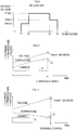
- the charger 50 is provided with power supply terminals 54a, 54b for receiving power supply from an external power source through the power cord 54, a rectifier 60 for full-wave rectifying an AC voltage supplied from the external power source to the power supply terminals 54a, 54b, a capacitor C1 for smoothing a DC voltage rectified by the rectifier 60, and an isolation transformer 62 of which primary winding is connected in parallel to the capacitor C1 via a switching element 64.
- the isolation transformer 62 is provided for insulation between the external power source and the internal circuits, as well as for reducing the DC voltage smoothed by the capacitor C1 to be taken into the charger 50.
- the switching element 64 is connected to one end of the grounded capacitor C1 by being provided between one end of the primary winding and the ground.
- the switching element 64 causes secondary winding of the isolation transformer 62 to generate a stepped down AC power by switching ON/OFF between one of the capacitor C1 and the ground.
- the switching element 64 is constituted, for example, by an n-channel MOSFET, which is turned on when a high level signal is input to a gate through a resistor Rc.
- a capacitor C2 is connected in parallel to the secondary winding of the isolation transformer 62 via a diode 66 for rectification.
- a DC voltage is charged to the capacitor C2 by the switching of the switching element 64.
- the DC voltage is used as a charging voltage to the battery 10.
- the positive side and the negative side of the capacitor C2 are respectively connected to the positive terminal 57 and the negative terminal 56.
- a charging switch 68 to conduct or block the path is provided.
- the charging switch 68 is a power semiconductor switch configured by a pair of FETs 68a, 68b. Each gate of the FETs 68a, 68b is connected to the conduction path on the positive electrode side through a resistor Ra, and is connected to the conduction path on the negative electrode side through a resistor Rb and a switching element 69.
- the FETs 68a, 68b are configured as p-channel MOSFETs.
- the resistors Ra, Rb and the switching element 69 during the on-time of the switching element 69, lower a level of a gate potential of each of the FETs 68a, 68b, thereby conducting the conduction path on the positive electrode side. Also, during the off-time of the switching element 69, the level of the gate potential of each of the FETs 68a, 68b is raised to high, thereby blocking the conduction path on the positive electrode side.
- Diodes Da, Db shown in FIG. 2 are parasitic diodes of the FETs 68a, 68b, respectively.
- the switching element 69 is configured, for example, as an n-channel MOSFET. The switching element 69 is turned off when the gate potential is at low level, and is turned on when the gate potential is at high level.
- a current detector 78 is provided for detecting a charging current flowing during charging of the battery 10.
- the current detector 78 is constituted by, for example, resistors provided in series in the conduction path on the negative electrode side, and a detector that outputs both-end voltages of the resistors as a detection result of the current.
- a detection signal from the current detector 78 is input to the current controller 76 that controls the charging current in accordance with a command from the charge controller 80.
- the current controller 76 outputs a switching signal to a driver 72 that drives the switching element 64 via a photocoupler 74, thereby turning on and off the switching element 64 to control the charging current to the battery 10.
- the photocoupler 74 is constituted by a light emitting diode Dr and a phototransistor Tf. Due to application of a forward voltage to the light emitting diode Dr via a resistor Rd from the current controller 76, the light emitting diode Dr emits light, and the phototransistor Tf is then turned on.
- the internal circuits of the charger 50 and the external power source are to be insulated by the photocoupler 74 as well.
- a voltage detector 82 is connected to a conduction path between the charging switch 68 and the positive terminal 56.
- the voltage detector 82 detects a voltage Vb of the conduction path as a battery voltage.
- the battery voltage Vb detected by the voltage detector 82 is input to the charge controller 80.
- the charge controller 80 controls the charging current controlled by the current controller 76 so that the battery voltage Vb reaches a charge completion voltage that is a target voltage based on the battery voltage Vb detected by the voltage detector 82.
- the charge controller 80 is configured as a microcomputer mainly including a CPU, a ROM, a RAM and the like.
- the charge controller 80 generates a pulse width modulated signal (PWM signal) as a command signal for the current controller 76 to control the charging current, and outputs the generated signal to an output circuit 79.
- PWM signal pulse width modulated signal
- the output circuit 79 converts the PWM signal to an analog voltage by an integrator constituted by a resistor Re and a capacitor C3, and outputs the analog voltage to the current controller 76 via a buffer configured as an operational amplifier OP1 and a resistor Rf.
- the charge controller 80 during charging of the battery 10, turns on the charging switch 68 via the switching element 69, thereby conducting the charging path to the battery 10.
- the charge controller 80 turns on the charging switch 68 via the switching element 69, thereby conducting the charging path to the battery 10.
- the charge controller 80 since the battery 10 is a lithium ion battery, the charge controller 80, after the start of charging the battery 10, performs constant current charging by outputting a PWM signal at a predetermined duty ratio to the output circuit 79 until the battery voltage Vb reaches a predetermined charge completion voltage.
- constant voltage control to maintain the charge completion voltage of the battery 10 is performed by controlling the duty ratio of the PWM signal for a given period, thereby to charge the battery 10 to a fully charged state.
- the battery 10 is a lithium ion battery
- a maximum voltage of the battery during charging is defined by the battery temperature.
- the charge controller 80 sets the charge completion voltage and an abnormality determination voltage according to the defined battery temperature-to-voltage characteristic.
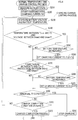
- the charge controller 80 at the start of charging the battery 10 and during the charging, periodically performs a voltage setting process shown in FIG. 3 at predetermined time intervals, and sets the charge completion voltage used for charge control and the abnormality determination voltage of the battery voltage.
- the charge controller 80 first acquires a battery temperature detected in the temperature detector 42 inside the battery pack 2 in communication with the battery controller 40, in S110.
- the charge controller 80 determines whether or not the battery temperature acquired in S110 is in a normal temperature region of T2 to T3. Then, if the battery temperature is in the normal temperature region, the process proceeds to S130.
- the charge controller 80 sets a maximum voltage (Vmax1) of the battery in the normal temperature region as the abnormality determination voltage, and sets a voltage (Vmax1- ⁇ V1) lower by a predetermined voltage ⁇ V1 than the maximum voltage (Vmax1) as the charge completion voltage. Thereby, the voltage setting process ends.
- the process proceeds to S140.
- the charge controller 80 determines whether or not the battery temperature is in a low temperature region which is not less than T1 but less than T2. Then, if the battery temperature is in the low temperature region, the process proceeds to S150.
- the charge controller 80 sets a maximum voltage (Vmax2) of the battery in the low temperature region as the abnormality determination voltage, and sets a voltage (Vmax2-AV2) lower by a predetermined voltage ⁇ V2 than the maximum voltage (Vmax2) as the charge completion voltage. Thereby, the voltage setting process ends.
- the process proceeds to S160.
- the charge controller 80 determines whether or not the battery temperature is in a high temperature region which is more than T3 but not more than T4. Then, if the battery temperature is in the high temperature region, the process proceeds to S170.
- the charge controller 80 sets a maximum voltage (Vmax3) of the battery in the high temperature region as the abnormality determination voltage, and sets a voltage (Vmax3- ⁇ V3) lower by a predetermined voltage ⁇ V3 than the maximum voltage (Vmax3) as the charge completion voltage. Thereby, the voltage setting process ends.
- the charge controller 80 determines in S160 that the battery temperature is not in the high temperature region, the battery temperature is out of the chargeable temperature region of T1 to T4. Thus, the charge controller 80 prohibits charging of the battery 10. Thereby, the voltage setting process ends.
- the charge controller 80 charges the battery 10 with the charge completion voltage which is set according to the battery temperature in the voltage setting process as the target voltage. During the charging, if the battery voltage exceeds the abnormality determination voltage, the charge controller 80 determines that abnormality has occurred and stops charging of the battery 10.
- the battery voltage may become higher than the charge completion voltage or the abnormality determination voltage, and then charging of the battery 10 may be stopped.
- a normal temperature time charge control process is performed with the procedure shown in FIG. 4 .
- the charge controller 80 measures a battery state in S210 in communication with the battery controller 40 and by taking in the battery voltage from the battery voltage detector 82. If there is no problem in the battery state, the process proceeds to S220. The charge controller 80 starts charging of the battery 10 with a preset charging current I1 at normal temperature.
- the charge controller 80 executes a charging current limiting process that reduces the charging current according to the battery voltage and the battery temperature.
- the charge controller 80 measures the battery voltage and the battery temperature at the present in S230.
- the charge controller 80 determines whether the battery temperature is in a temperature range between a set temperature (T3- ⁇ ) lower by the predetermined temperature ( ⁇ ) than a high temperature determining threshold (T3) and the high temperature determination threshold (T3), and whether or not the battery voltage is in a voltage range between a high temperature time voltage (Vmax3) that is a maximum voltage at high temperature and a normal voltage (Vmax1) that is a maximum voltage at normal temperature.
- the process of S240 is to determine whether or not the battery temperature and the battery voltage are in a region A shown in FIG. 5 , that is, whether or not the battery temperature is in a temperature region just before changing from the normal temperature region to the high temperature region, and the battery voltage is the charge completion voltage on the high temperature side in which the battery voltage is changed with the change of the battery temperature and is in a voltage range which exceeds the charge completion voltage.
- the charge controller 80 determines in S240 that the battery temperature and the battery voltage are in the region A shown in FIG. 5 , it is determined in S250 whether or not the battery temperature is increasing based on the change of the battery temperature measured in S230.
- the process proceeds to S260.
- the charge controller 80 changes the charging current to a current 12 which is smaller than a current I1 at the present. Then, the process proceeds to S270.
- the charge controller 80 determines in S240 that the battery temperature and the battery voltage are not in the region A shown in FIG. 5 , or determines in S250 that the battery temperature is not increasing, the process moves to S270.
- the charge controller 80 determines whether or not the battery temperature is in a temperature range between a low temperature determination threshold (T2) and a set temperature (T2+ ⁇ ) which is higher by the predetermined temperature ( ⁇ ) than the low temperature threshold (T2), and the battery voltage is in a voltage range between a low temperature time voltage (Vmax2) that is a maximum voltage at low temperature and the normal voltage (Vmax1) that is the maximum voltage at normal temperature.
- the process of S270 is to determine whether or not the battery temperature and the battery voltage are in a region B shown in FIG. 5 , that is, whether the battery temperature is in a temperature region just before changing from the normal temperature region to the low temperature region, and the battery voltage is the charge completion voltage on the low temperature side in which the battery voltage is changed with the change of the battery temperature and is in a voltage range which exceeds the charge completion voltage.
- the charge controller 80 determines in S270 that the battery temperature and the battery voltage are in the region B shown in FIG. 5 , it is determined in S280 whether or not the battery temperature is decreasing based on the change of the battery temperature measured in S230.
- the process proceeds to S290.
- the charge controller 80 changes the charging current to a current 13 which is smaller than the current I1 at the present.
- the process moves to S300.
- the charge controller 80 determines in S270 that the battery temperature and the battery voltage are not in the region B shown in FIG. 5 or determines in S280 that the battery temperature is not decreasing, the process moves to S300.
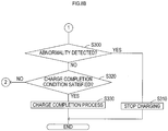
- the charge controller 80 determines whether or not the battery voltage exceeds the abnormality determination voltage and whether or not abnormality is detected on the battery pack 2 side, thereby to determine whether or not abnormality has occurred in the battery 10 and in the charging system.
- the process proceeds to S320.
- the charge controller 80 determines whether or not the battery voltage has reached the charge completion voltage.
- the process proceeds to S330.
- the charge controller 80 continues charging of the battery for a predetermined time with the charge completion voltage thereby to execute a charge completion process which fully charges the battery 10. Thereby, the normal temperature time charge control process ends.
- the charge controller 80 not only charges the battery voltage to the charge completion voltage, but also, when the battery temperature and the battery voltage are in the region A or B shown in FIG. 5 , reduces the charging current from the current I1 at the normal time to the current 12 or I3.
- the charging current is switched from I1 to I2 at time t1, and, with the decrease of the charging current, the battery voltage decreases, as shown in FIG. 6 .
- the battery temperature thereafter exceeds the high temperature determination threshold (T3), and the charge completion voltage and the abnormality determination voltage are changed to the high temperature time voltages, it is possible to inhibit termination of charging of the battery 10 caused by the battery voltage greater than the charge completion voltage and the abnormal determination voltage.
- the battery 10 can be charged to a fully charged state (time t2).
- the charging current is switched from I1 to I3 at time t1, and, with the decrease of the charging current, the battery voltage decreases, as shown in FIG. 7 .
- the battery temperature thereafter falls below the low temperature determination threshold (T2), and the charge completion voltage and the abnormality determination voltage are changed to the low temperature time voltages, it is possible to inhibit termination of charging of the battery 10 caused by the battery voltage greater than the charge completion voltage and the abnormality determination voltage.
- the battery 10 can be charged to a fully charged state (time t2).
- the charge controller 80 sets the charge completion voltage and the abnormality determination voltage in the voltage setting process in FIG. 3 .
- the charge controller 80 determines that abnormality has occurred in the battery 10, and stops charging the battery 10.
- the change of the abnormality determination voltage from the normal temperature region to the high or low temperature region is also inhibited, erroneous detection of abnormality of the battery 10 with the change of the abnormality determination voltage can be inhibited. Further, it is possible to inhibit misunderstanding or a sense of distrust from occurring to the user by the erroneous detection.
- the charge controller 80 determines whether the battery temperature is increasing. Only when the battery temperature is increasing, the charge controller 80 reduces the charging current. When the battery voltage and the battery temperature are in the region B shown in FIG. 5 , the charge controller 80 determines whether the battery temperature is decreasing. Only if the battery temperature is decreasing, the charge controller 80 reduces the charging current.
- the charging current is not reduced in case that the charge completion voltage and the abnormality determination voltage are not changed to the high or low temperature time voltages. Thereby, it is possible to inhibit the charging time required to fully charge the battery 10 from becoming longer.
- the battery voltage detector 82 corresponds to an example of the voltage detector of the present invention
- the temperature detector 42 corresponds to an example of the temperature detector of the present invention.
- functions as the voltage setting unit and the charging current limiting unit of the present invention are implemented by the voltage setting process and the normal temperature time charge control process executed by the charge controller 80 of the charger 50 (charging current limiting process of S230 to S290 for details).
- the set temperature (T3- ⁇ ) corresponds to an example of the low set temperature of the present invention and the set temperature (T2+ ⁇ ) corresponds to an example of the high set temperature of the present invention.
- the present invention is not limited to the above embodiment, and can take various modes within the scope of the present invention as defined by the claims.
- the charging current is changed from I1 to I2 or 13 in S260 or S290 in FIG. 4 , the current is retained as a charging current. Even if the battery temperature returns to an intermediate region between the set temperature (T2+ ⁇ ) and the set temperature (T3- ⁇ ), the battery 10 will be charged by the charging current I2 or I3 after the change.
- the charge controller 80 determines in S410 whether the battery temperature is or is below a set temperature (T3- ⁇ -x) which is obtained by subtracting a predetermined temperature ⁇ and a margin x from the high temperature determination threshold (T3). If the battery temperature is or is below the set temperature if (T3- ⁇ -x), the charging current may be returned to I1 in S420.
- the charge controller 80 determines in S430 whether the battery temperature is or is above a set temperature (T2+ ⁇ +y) which is obtained by adding a predetermined temperature ⁇ and a margin y to the low temperature determination threshold (T2). If the battery temperature is or is above the set temperature (T2+ ⁇ +y), the charging current may be returned to I1 in S440.
- T2+ ⁇ +y a set temperature which is obtained by adding a predetermined temperature ⁇ and a margin y to the low temperature determination threshold (T2). If the battery temperature is or is above the set temperature (T2+ ⁇ +y), the charging current may be returned to I1 in S440.
- the charging time of the battery 10 can be shortened as compared to the embodiment described above
- values obtained by adding a prescribed margin ⁇ and ⁇ to the defined high and low temperature time voltages (maximum voltages) Vmax3 and Vmax2, for example, Vmax2- ⁇ or above and Vmax1 or below, Vmax3- ⁇ or above and Vmax1 or below, etc., may be used as the high and low temperature time voltages.
- the same voltages can be set depending on the battery temperature-to-voltage characteristic of the battery 10.
- the normal voltage at normal temperature used to determine the regions A and B it is possible to use a value obtained by adding a predetermined margin to the defined voltage (maximum voltage) Vmax1 at normal temperature.
- the maximum voltages Vmax1, Vmax2 and Vmax3 defined by the battery temperature-to-voltage characteristic of the battery 10 are used for the abnormality determination voltage.
- the abnormality determination voltage it is possible to set a value obtained by subtracting a predetermined voltage from each of the maximum voltages Vmax1, Vmax2 and Vmax3, similar to the charge completion voltage.
- the functions of the charge control device of the present invention may be implemented on the battery pack 2 side by executing the voltage setting process and the charging current limiting process by the battery controller 40 of the battery pack 2.
Description
- The present invention relates to a charge control device that changes a charge completion voltage or an abnormality determination voltage according to the temperature of a battery.
- Conventionally, in a lithium ion battery, a temperature range at the time of charging is classified to three regions, i.e., a low temperature region (T1 to T2), a normal temperature region (T2 to T3), and a high temperature region (T3 to T4), as illustrated in
FIG. 9 . Per region, a maximum voltage Vmax of the battery is defined (for example, see Japanese Unexamined Patent Application Publication No.2009-55729 - Therefore, a charge control device of this type that controls charging of a battery is adapted to set a charge completion voltage as a target voltage during charging and an abnormality determination voltage for determining abnormality of the battery, per the temperature range, so that the battery voltage during charging does not exceed the maximum voltage Vmax defined as above.
US 2009/085527 A1 relates to charging a secondary battery in a manner such that the surface temperature of the secondary battery does not exceed an upper temperature limit. For different temperature ranges, different charging currents and upper charging voltage limits are defined.US 2008/224667 A1 relates to a method for charging a lithium-ion secondary battery and pertains to a charging method for fully charging a degraded lithium-ion secondary battery in safe manner. - In the charge control device of the prior art as above, when the battery temperature in the normal temperature region (T2 to T3) is raised by charging and exceeds a high temperature determination threshold (T3) which is an upper limit temperature in the normal temperature region, the charge completion voltage or the abnormality determination voltage is reduced from a normal voltage (Vmax1) to a high temperature time voltage (Vmax3) shown in
FIG. 9 . - Then, at the time of the voltage change, if the battery voltage has not reached the high temperature time voltage (Vmax3), charging of the battery is continued. However, as shown in
FIG. 10 , if the battery voltage is or is above the high temperature time voltage (Vmax3), it is determined that the battery voltage has reached the charge completion voltage or the abnormality determination voltage, and charging of the battery is stopped. - As above, when the charge completion voltage or the abnormality determination voltage is changed with the increase in battery temperature, and charging of the battery is stopped by the voltage change, the battery cannot be fully charged and remains insufficiently charged.
- Also, when charging of the battery is stopped by change of the abnormality determination voltage with the increase in battery temperature, it means that the battery which is normal in nature is determined abnormal, thereby misleading a user.
- Such problem occurs also when the external ambient temperature is low, and heat radiation of the battery is greater than the heat generated by charging.
- That is, under such conditions, the battery temperature, which is in the normal temperature region (T2 to T3) at the start of charging the battery, may decrease after the start of charging and may fall below a low temperature determination threshold (T2) that is a lower limit temperature in the normal temperature region.
- In this case, the charge control device lowers the charge completion voltage or the abnormality determination voltage from the normal voltage (Vmax1) to a low temperature time voltage (Vmax2) shown in
FIG. 9 . As shown inFIG. 11 , if the battery voltage is or is above the low temperature time voltage (Vmax2) at the time of the voltage change, the charging of the battery is stopped. - Therefore, even when the battery temperature decreases during charging, the same problems as those at the time of the increase in battery temperature occur that the charging of the battery is stopped, thereby resulting in the insufficiently charged battery or that the abnormality of the battery is erroneously determined, thereby misleading the user.
- An object of the present invention, in a charge control device that changes a charge completion voltage or an abnormality determination voltage according to the temperature of a battery, is to inhibit occurrence of an insufficient charged battery or erroneous determination of abnormality of a battery due to termination of charging of the battery immediately after voltage change.
- The charge control device according to the invention is defined by the
independent claims - In the above charge control device, according to one aspect of the invention, when the battery temperature detected by the temperature detector is or is above a high temperature determination threshold set in advance, the voltage setting unit sets at least one of the charge completion voltage and the abnormality determination voltage to a high temperature time voltage that is lower than a normal voltage.
- In addition, during charging of the battery by the charger, when the battery temperature is in a temperature range between a high set temperature that is lower by a predetermined temperature than the high temperature determination threshold and the high temperature determination threshold, and when the battery voltage is in a voltage range between the normal voltage and the high temperature time voltage, the charging current limiting unit reduces the charging current supplied to the battery from the charger.
- Here, the charge completion voltage and the abnormality determination voltage described above are voltages set in advance in the charger so that charging of the battery is stopped when the battery voltage reaches the preset charge completion voltage or the abnormality determination voltage that is higher than the charge completion voltage.
- Because the battery voltage during charging is determined by an internal impedance of the battery and the charging current (battery voltage = open circuit voltage + internal impedance × charging current), the charging current limiting unit lowers the battery voltage by reducing the charging current under the above described conditions.
- According to the charge control device described above, when the battery temperature exceeds the high temperature determination threshold during charging of the battery, and the charge completion voltage or the abnormality determination voltage is changed from the normal voltage to the high temperature time voltage, it is possible to inhibit termination of charging of the battery due to the battery voltage exceeding the high temperature time voltage.
- Further, because a heating amount of the battery is determined by the internal impedance of the battery and the charging current (heat value = internal impedance × charging current × charging current), it is also possible to reduce the heating amount of the battery (in other words, increase in battery temperature) by reducing the charging current under the above described conditions.
- Therefore, according to the charge control device described above, it is possible to lengthen charging time during which the battery temperature exceeds the high temperature determination threshold at the time of charging of the battery, i.e., time for the charge completion voltage or the abnormality determination voltage to be changed from the normal voltage to the high temperature time voltage.
- Therefore, according to the charge control device described above, it is possible to inhibit the battery from being unable to be fully charged due to termination of charging of the battery before fully charged after the start of charging the battery.
- Also, if the voltage setting unit sets the abnormality determination voltage, it is possible to inhibit erroneous detection of abnormality of the battery by the charger with the change of the abnormality determination voltage, and to inhibit misunderstanding or a sense of distrust from occurring to the user by the erroneous detection.
- In the charge control device of another aspect of the present invention, when the battery temperature detected by the temperature detector is or is below the low temperature determination threshold set in advance, the voltage setting unit sets at least one of the charge completion voltage and the abnormality determination voltage to a low temperature time voltage which is lower than the normal voltage.
- The charging current limiting unit, when the battery temperature is in a temperature range between a low set temperature that is higher by a predetermined temperature than a low temperature determination threshold and the low temperature determination threshold, and the battery voltage is in a voltage range between the normal voltage and a low temperature time voltage, during charging of the battery by the charger, reduces the charging current supplied to the battery by the charger, thereby reducing the battery voltage.
- Therefore, according to the charge control device of the another aspect, it is possible to inhibit termination of charging of the battery due to the battery voltage exceeding the low temperature time voltage, when the battery temperature falls below the low temperature determination threshold during charging of the battery, and the charge completion voltage or the abnormal determination voltage is changed from the normal voltage to the low temperature time voltage.
- Therefore, according to the charge control device of the another aspect above, it is possible to inhibit the battery from not being able to be fully charged, similar to the charge control device of the one aspect above.
- In the charge control devices of the one aspect and of the another aspect above, the charging current limiting unit may be adapted to retain the charging current once reducing the charging current even if the battery temperature deviates from the temperature range.
- According to the charge control device as such, it is possible to inhibit rising and falling of the charging current by change of battery temperature, which facilitates control of the charging current.
- In the charge control device according to the one aspect above, the charging current limiting unit may increase the charging current after reducing the charging current, when the battery temperature deviates from the temperature range and falls below the high set temperature.
- Also, in the charge control device of the another aspect above, the charging current limiting unit may increase the charging current after reducing the charging current, when the battery temperature deviates from the temperature range and is raised above the low set temperature.
- According to the charge control device as such, the charging current limiting unit in the devices of the one aspect and the another aspect above increases the charging current after reducing the charging current, when the battery temperature returns to the temperature region before reducing the charging current, thereby being able to shorten the charging time of the battery.
- In the charge control device of the one aspect above, even if the battery temperature is in the temperature range between the high set temperature and the high temperature determination threshold, and the battery voltage is in the voltage range between the high temperature time voltage and the normal voltage, the voltage setting unit does not change the charge completion voltage or the abnormality determination voltage from the normal voltage to the high temperature time voltage if the battery temperature does not increase further.
- Therefore, in the charge control device, the charging current limiting unit may be configured so as to reduce the charging current on condition that the battery temperature is increasing when the battery temperature is within the aforementioned temperature range and the battery voltage is within the aforementioned voltage range.
- If the charging current limiting unit is configured as such, it is possible to inhibit the charging time of the battery from becoming longer due to reduction of the charging current by the charging current limiting unit when the battery temperature is not increasing.
- In addition, in the charge control device of the another aspect, even if the battery temperature is in the temperature range between the low temperature determination threshold and the low set temperature, and the battery voltage is in the voltage range between the low temperature time voltage and the normal voltage, the voltage setting unit does not change the charge completion voltage or the abnormality determination voltage from the normal voltage to the low temperature time voltage, if the battery temperature does not decrease further.
- Therefore, in the charge control device, the charging current limiting unit may be configured to reduce the current on condition that the battery temperature is decreasing when the battery temperature is within the aforementioned temperature range and the battery voltage is within the aforementioned voltage range.
- If the charging current limiting unit is configured as such, it is possible to inhibit the charging time of the battery from becoming longer due to reduction of the charging current by the charging current limiting unit when the battery temperature is not decreasing.
- An embodiment of the present invention will be described below with reference to the accompanying drawings in which:
-
FIG. 1 is a perspective view illustrating an appearance of a battery pack and a charger of an embodiment; -
FIG. 2 is a circuit diagram showing a circuit configuration of the battery pack and the charger of the embodiment; -
FIG. 3 is a flowchart representing a voltage setting process executed in a charge controller; -
FIG. 4 is a flowchart illustrating a normal temperature time charge control process executed in the charge controller; -
FIG. 5 is an explanatory diagram for explaining a switching operation of a charging current by the normal temperature time charge control process; -
FIG. 6 is an explanatory diagram showing change of battery voltage caused by switching of the charging current at the time of increase in battery temperature; -
FIG. 7 is an explanatory diagram showing change of battery voltage caused by switching of the charging current at the time of decrease in battery temperature; -
FIGS. 8A and8B are flowcharts showing a modification of the normal temperature time charge control process; -
FIG. 9 is a schematic diagram of the battery voltage during charging which is defined according to the battery temperature; -
FIG. 10 is an explanatory diagram for explaining an operation to stop charging caused when a charge completion voltage or an abnormality determination voltage is changed at the time of increase in battery temperature; and -
FIG. 11 is an explanatory diagram for explaining an operation to stop charging caused when a charge completion voltage or an abnormality determination voltage is changed at the time of decrease in battery temperature. - As shown in
FIG. 1 , a charging system of the present embodiment includes abattery pack 2, and acharger 50 for charging thebattery pack 2. The battery pack is detachably mounted on various rechargeable power equipment, such as, for example, a rechargeable power tool, a rechargeable vacuum cleaner, a rechargeable mowing device, and the like, and supplies power to a direct current (DC) motor or the like which is a power source of the various rechargeable power equipment. - The
charger 50 receives power from an external power supply (generally, alternate current (AC) voltage from a commercial power supply) via apower cord 54, generates a charging voltage (DC voltage) for charging a battery and supplies the generated power to a battery 10 (seeFIG. 3 ) inside thebattery pack 2. - An
attachment 52 for attaching (in other words, mounting) thebattery pack 2 is formed on a top surface of thecharger 50. Theattachment 52 is formed to conform with the shape of an attachment 3 of an underside surface of thebattery pack 2 so that thebattery pack 2 can be slidably mounted. - In addition, the
attachment 52 is provided with aterminal portion 53 which can be fitted to a terminal 4 formed on the underside surface of thebattery pack 2 when thebattery pack 2 is mounted. - The
terminal portion 53 of thecharger 50 and the terminal 4 of thebattery pack 2 are respectively provided withterminals 56 to 58 and 6 to 8 (seeFIG. 2 ). Theterminals 56 to 58 and 6 to 8 are connected to each other when thebattery pack 2 is mounted to theattachment 52 of thecharger 50. - Note that, in the
battery pack 2, theterminals 6 and 7 are a positive terminal and a negative terminal respectively connected to a positive electrode and a negative electrode of thebattery 10, and flow a charging current from thecharger 50 and a discharging current to the rechargeable power equipment. The terminal 8 is a communication terminal for communicating with thecharger 50 or the rechargeable power equipment. - Also, in the
charger 50, theterminals positive terminal 6 and the negative terminal 7 of thebattery pack 2 and charge thebattery 10 when thebattery pack 2 is mounted. The terminal 58 is a communication terminal to be connected to the terminal 8 of thebattery pack 2 and communicates with thebattery pack 2. - Now, a circuit configuration of the
battery pack 2 and thecharger 50 will be described with reference toFIG. 2 . - As shown in
FIG. 2 , thebattery 10 including a plurality of (five in the figure) series-connectedcells battery pack 2. - The positive electrode of the
battery 10 is connected to thepositive terminal 6, and the negative electrode of thebattery 10 is connected to the negative terminal 7. Thebattery 10 is a lithium ion battery, as shown inFIG. 9 , which is required to define an upper limit of the battery voltage during charging according to the battery temperature. - Also, the
battery pack 2 is provided with avoltage monitor 20, abattery controller 40, atemperature detector 42, and acurrent detector 44. - The voltage monitor 20 serves to monitor cell voltages Vc1 to Vc5 of the
cells 11 to 15 by taking in both-end voltages of thecells 11 to 15 constituting thebattery 10 through resistors R10 to R15. - The monitoring result (that is, cell voltages Vc1 to Vc5) is input to the
battery controller 40 and used to detect abnormality of thecells 11 to 15 or fluctuations of the cell voltages Vc1 to Vc5. - The
temperature detector 42 detects an internal temperature of the battery 10 (cell temperature) via a temperature detecting element (not shown) incorporated in thebattery 10, and outputs the detection result to thebattery controller 40, in order to prevent overheating of thebattery 10. - The
current detector 44 is provided in a conduction path to the negative electrode of thebattery 10 from the negative terminal 7, and detects a current flowing through this path. Thecurrent detector 44 includes, for example, resistors provided in series in the conduction path, and a detector that outputs both-end voltages of the resistors to thebattery controller 40 as a detection result of the current. - The
battery controller 40 is configured as a microcomputer mainly including a CPU, a ROM, a RAM and the like. - The
battery controller 40 takes in the monitoring result of the cell voltages Vc1 to Vc5 by thevoltage monitor 20, and the detection results by thetemperature detector 42 and thecurrent detector 44, and detects a state of thebattery 10 based on the respective parameters taken in. - Also, the
battery controller 40 is equipped with a communication port for communicating with thecharger 50 and the rechargeable power equipment mounting thebattery pack 2. The communication port is connected to the communication terminal 8 through a communication line. - Upon detecting abnormality of the cell voltage, charging and discharging current, battery temperature, etc. based on the above parameters, the
battery controller 40 sends an abnormality detection signal to thecharger 50 and the rechargeable power equipment via the communication terminal 8 to stop charging and discharging of thebattery 10. Also, thebattery controller 40 transmits the detection results of the battery temperature, etc. in accordance with requests input from thecharger 50 and the rechargeable power equipment via the communication terminal 8. - The
battery pack 2 is also provided with a power source (not shown) that receives power supply from thebattery 10 and generates a source voltage (DC constant voltage) Vcc for driving internal circuits such as thebattery controller 40 and the like. - Next, the
charger 50 is provided withpower supply terminals power cord 54, arectifier 60 for full-wave rectifying an AC voltage supplied from the external power source to thepower supply terminals rectifier 60, and anisolation transformer 62 of which primary winding is connected in parallel to the capacitor C1 via a switchingelement 64. - The
isolation transformer 62 is provided for insulation between the external power source and the internal circuits, as well as for reducing the DC voltage smoothed by the capacitor C1 to be taken into thecharger 50. - That is, the switching
element 64 is connected to one end of the grounded capacitor C1 by being provided between one end of the primary winding and the ground. The switchingelement 64 causes secondary winding of theisolation transformer 62 to generate a stepped down AC power by switching ON/OFF between one of the capacitor C1 and the ground. - The switching
element 64 is constituted, for example, by an n-channel MOSFET, which is turned on when a high level signal is input to a gate through a resistor Rc. - Also, a capacitor C2 is connected in parallel to the secondary winding of the
isolation transformer 62 via adiode 66 for rectification. A DC voltage is charged to the capacitor C2 by the switching of the switchingelement 64. The DC voltage is used as a charging voltage to thebattery 10. - For this reason, the positive side and the negative side of the capacitor C2 are respectively connected to the
positive terminal 57 and thenegative terminal 56. - Also, in a conduction path between the positive electrode side of the capacitor C2 and the
positive terminal 56, a chargingswitch 68 to conduct or block the path is provided. - The charging
switch 68 is a power semiconductor switch configured by a pair ofFETs FETs element 69. - The
FETs element 69, during the on-time of the switchingelement 69, lower a level of a gate potential of each of theFETs element 69, the level of the gate potential of each of theFETs - Diodes Da, Db shown in
FIG. 2 are parasitic diodes of theFETs element 69 is configured, for example, as an n-channel MOSFET. The switchingelement 69 is turned off when the gate potential is at low level, and is turned on when the gate potential is at high level. - In the conduction path on the negative electrode side between the capacitor C2 and the
negative terminal 57, acurrent detector 78 is provided for detecting a charging current flowing during charging of thebattery 10. - Similar to the
current detector 44 inside thebattery pack 2, thecurrent detector 78 is constituted by, for example, resistors provided in series in the conduction path on the negative electrode side, and a detector that outputs both-end voltages of the resistors as a detection result of the current. - A detection signal from the
current detector 78 is input to thecurrent controller 76 that controls the charging current in accordance with a command from thecharge controller 80. - The
current controller 76 outputs a switching signal to adriver 72 that drives the switchingelement 64 via aphotocoupler 74, thereby turning on and off the switchingelement 64 to control the charging current to thebattery 10. - The
photocoupler 74 is constituted by a light emitting diode Dr and a phototransistor Tf. Due to application of a forward voltage to the light emitting diode Dr via a resistor Rd from thecurrent controller 76, the light emitting diode Dr emits light, and the phototransistor Tf is then turned on. - Accordingly, the internal circuits of the
charger 50 and the external power source are to be insulated by thephotocoupler 74 as well. - Also, a
voltage detector 82 is connected to a conduction path between the chargingswitch 68 and thepositive terminal 56. Thevoltage detector 82 detects a voltage Vb of the conduction path as a battery voltage. The battery voltage Vb detected by thevoltage detector 82 is input to thecharge controller 80. - The
charge controller 80 controls the charging current controlled by thecurrent controller 76 so that the battery voltage Vb reaches a charge completion voltage that is a target voltage based on the battery voltage Vb detected by thevoltage detector 82. Thecharge controller 80 is configured as a microcomputer mainly including a CPU, a ROM, a RAM and the like. - The
charge controller 80 generates a pulse width modulated signal (PWM signal) as a command signal for thecurrent controller 76 to control the charging current, and outputs the generated signal to anoutput circuit 79. - The
output circuit 79 converts the PWM signal to an analog voltage by an integrator constituted by a resistor Re and a capacitor C3, and outputs the analog voltage to thecurrent controller 76 via a buffer configured as an operational amplifier OP1 and a resistor Rf. - In addition, the
charge controller 80, during charging of thebattery 10, turns on the chargingswitch 68 via the switchingelement 69, thereby conducting the charging path to thebattery 10. When charging of thebattery 10 is completed and if a transmission signal from thebattery pack 2 or abnormality is detected based on the battery voltage Vb detected by thevoltage detector 82, turns off the chargingswitch 68 to stop charging. - In the present embodiment, since the
battery 10 is a lithium ion battery, thecharge controller 80, after the start of charging thebattery 10, performs constant current charging by outputting a PWM signal at a predetermined duty ratio to theoutput circuit 79 until the battery voltage Vb reaches a predetermined charge completion voltage. - Further, when the battery voltage Vb reaches the charge completion voltage by the constant current charging, constant voltage control to maintain the charge completion voltage of the
battery 10 is performed by controlling the duty ratio of the PWM signal for a given period, thereby to charge thebattery 10 to a fully charged state. - Also, since the
battery 10 is a lithium ion battery, a maximum voltage of the battery during charging is defined by the battery temperature. - Therefore, the
charge controller 80 sets the charge completion voltage and an abnormality determination voltage according to the defined battery temperature-to-voltage characteristic. - That is, the
charge controller 80, at the start of charging thebattery 10 and during the charging, periodically performs a voltage setting process shown inFIG. 3 at predetermined time intervals, and sets the charge completion voltage used for charge control and the abnormality determination voltage of the battery voltage. - As shown in
FIG. 3 , in the voltage setting process, thecharge controller 80 first acquires a battery temperature detected in thetemperature detector 42 inside thebattery pack 2 in communication with thebattery controller 40, in S110. - Next, in S120, the
charge controller 80 determines whether or not the battery temperature acquired in S110 is in a normal temperature region of T2 to T3. Then, if the battery temperature is in the normal temperature region, the process proceeds to S130. Thecharge controller 80 sets a maximum voltage (Vmax1) of the battery in the normal temperature region as the abnormality determination voltage, and sets a voltage (Vmax1-ΔV1) lower by a predetermined voltage ΔV1 than the maximum voltage (Vmax1) as the charge completion voltage. Thereby, the voltage setting process ends. - If the
charge controller 80 determines in S120 that the battery temperature is not in the normal temperature region, the process proceeds to S140. In S140, thecharge controller 80 determines whether or not the battery temperature is in a low temperature region which is not less than T1 but less than T2. Then, if the battery temperature is in the low temperature region, the process proceeds to S150. Thecharge controller 80 sets a maximum voltage (Vmax2) of the battery in the low temperature region as the abnormality determination voltage, and sets a voltage (Vmax2-AV2) lower by a predetermined voltage ΔV2 than the maximum voltage (Vmax2) as the charge completion voltage. Thereby, the voltage setting process ends. - If the
charge controller 80 determines in S140 that the battery temperature is not in the low temperature region, the process proceeds to S160. In S160, thecharge controller 80 determines whether or not the battery temperature is in a high temperature region which is more than T3 but not more than T4. Then, if the battery temperature is in the high temperature region, the process proceeds to S170. In S170, thecharge controller 80 sets a maximum voltage (Vmax3) of the battery in the high temperature region as the abnormality determination voltage, and sets a voltage (Vmax3-ΔV3) lower by a predetermined voltage ΔV3 than the maximum voltage (Vmax3) as the charge completion voltage. Thereby, the voltage setting process ends. - If the
charge controller 80 determines in S160 that the battery temperature is not in the high temperature region, the battery temperature is out of the chargeable temperature region of T1 to T4. Thus, thecharge controller 80 prohibits charging of thebattery 10. Thereby, the voltage setting process ends. - The
charge controller 80 charges thebattery 10 with the charge completion voltage which is set according to the battery temperature in the voltage setting process as the target voltage. During the charging, if the battery voltage exceeds the abnormality determination voltage, thecharge controller 80 determines that abnormality has occurred and stops charging of thebattery 10. - During the charging, as the battery temperature changes from the normal temperature region to the low temperature region or the high temperature region, and the charge completion voltage and the abnormality determination voltage are changed to the voltages lower than the voltages at the normal temperature in the voltage setting process, the battery voltage may become higher than the charge completion voltage or the abnormality determination voltage, and then charging of the
battery 10 may be stopped. - In the present embodiment, in order to reduce the probability that the battery voltage becomes higher than the charge completion voltage or the abnormality determination voltage when the charge completion voltage and the abnormality determination voltage are changed in this way, and to be able to charge the
battery 10 to a fully charged state after the change of the voltage, a normal temperature time charge control process is performed with the procedure shown inFIG. 4 . - As shown in
FIG. 4 , in the normal temperature time charge control process, thecharge controller 80 measures a battery state in S210 in communication with thebattery controller 40 and by taking in the battery voltage from thebattery voltage detector 82. If there is no problem in the battery state, the process proceeds to S220. Thecharge controller 80 starts charging of thebattery 10 with a preset charging current I1 at normal temperature. - Then, after the start of charging, the
charge controller 80, in S230 to S290, executes a charging current limiting process that reduces the charging current according to the battery voltage and the battery temperature. - In the charging current limiting process, the
charge controller 80 measures the battery voltage and the battery temperature at the present in S230. - In subsequent S240, the
charge controller 80 determines whether the battery temperature is in a temperature range between a set temperature (T3-α) lower by the predetermined temperature (α) than a high temperature determining threshold (T3) and the high temperature determination threshold (T3), and whether or not the battery voltage is in a voltage range between a high temperature time voltage (Vmax3) that is a maximum voltage at high temperature and a normal voltage (Vmax1) that is a maximum voltage at normal temperature. - The process of S240 is to determine whether or not the battery temperature and the battery voltage are in a region A shown in
FIG. 5 , that is, whether or not the battery temperature is in a temperature region just before changing from the normal temperature region to the high temperature region, and the battery voltage is the charge completion voltage on the high temperature side in which the battery voltage is changed with the change of the battery temperature and is in a voltage range which exceeds the charge completion voltage. - When the
charge controller 80 determines in S240 that the battery temperature and the battery voltage are in the region A shown inFIG. 5 , it is determined in S250 whether or not the battery temperature is increasing based on the change of the battery temperature measured in S230. - When the
charge controller 80 determines in S250 that the battery temperature is increasing, the process proceeds to S260. In S260, thecharge controller 80 changes the charging current to a current 12 which is smaller than a current I1 at the present. Then, the process proceeds to S270. - Also, when the
charge controller 80 either determines in S240 that the battery temperature and the battery voltage are not in the region A shown inFIG. 5 , or determines in S250 that the battery temperature is not increasing, the process moves to S270. - In S270, the
charge controller 80 determines whether or not the battery temperature is in a temperature range between a low temperature determination threshold (T2) and a set temperature (T2+β) which is higher by the predetermined temperature (β) than the low temperature threshold (T2), and the battery voltage is in a voltage range between a low temperature time voltage (Vmax2) that is a maximum voltage at low temperature and the normal voltage (Vmax1) that is the maximum voltage at normal temperature. - The process of S270 is to determine whether or not the battery temperature and the battery voltage are in a region B shown in
FIG. 5 , that is, whether the battery temperature is in a temperature region just before changing from the normal temperature region to the low temperature region, and the battery voltage is the charge completion voltage on the low temperature side in which the battery voltage is changed with the change of the battery temperature and is in a voltage range which exceeds the charge completion voltage. - When the
charge controller 80 determines in S270 that the battery temperature and the battery voltage are in the region B shown inFIG. 5 , it is determined in S280 whether or not the battery temperature is decreasing based on the change of the battery temperature measured in S230. - When the
charge controller 80 determines in S280 that the battery temperature is decreasing, the process proceeds to S290. In S290, thecharge controller 80 changes the charging current to a current 13 which is smaller than the current I1 at the present. The process moves to S300. - Also, when the
charge controller 80 either determines in S270 that the battery temperature and the battery voltage are not in the region B shown inFIG. 5 or determines in S280 that the battery temperature is not decreasing, the process moves to S300. - In S300, the
charge controller 80 determines whether or not the battery voltage exceeds the abnormality determination voltage and whether or not abnormality is detected on thebattery pack 2 side, thereby to determine whether or not abnormality has occurred in thebattery 10 and in the charging system. - When the
charge controller 80 determines in S300 that abnormality has occurred, the process proceeds to S310. In S310, thecharge controller 80 turns off the chargingswitch 68 to stop charging of thebattery 10. The normal temperature time charge control process is terminated. - On the other hand, if the
charge controller 80 determines that abnormality has not occurred in S300, the process proceeds to S320. Thecharge controller 80 determines whether or not the battery voltage has reached the charge completion voltage. - Then, if the battery voltage has reached the charge completion voltage, the process proceeds to S330. In S330, the
charge controller 80 continues charging of the battery for a predetermined time with the charge completion voltage thereby to execute a charge completion process which fully charges thebattery 10. Thereby, the normal temperature time charge control process ends. - As noted above, in the normal temperature time charge control process, the
charge controller 80 not only charges the battery voltage to the charge completion voltage, but also, when the battery temperature and the battery voltage are in the region A or B shown inFIG. 5 , reduces the charging current from the current I1 at the normal time to the current 12 or I3. - As a result, when the battery temperature reaches the set temperature on the high temperature side (T3-α), and the battery temperature and the battery voltage enter the region A, while the
battery 10 is being charged at normal temperature, the charging current is switched from I1 to I2 at time t1, and, with the decrease of the charging current, the battery voltage decreases, as shown inFIG. 6 . - For this reason, when the battery temperature thereafter exceeds the high temperature determination threshold (T3), and the charge completion voltage and the abnormality determination voltage are changed to the high temperature time voltages, it is possible to inhibit termination of charging of the
battery 10 caused by the battery voltage greater than the charge completion voltage and the abnormal determination voltage. Thebattery 10 can be charged to a fully charged state (time t2). - In addition, when the battery temperature is reduced to the set temperature on the low temperature side (T2+β), and the battery temperature and the battery voltage enter the region B, while the
battery 10 is being charged at normal temperature, the charging current is switched from I1 to I3 at time t1, and, with the decrease of the charging current, the battery voltage decreases, as shown inFIG. 7 . - For this reason, when the battery temperature thereafter falls below the low temperature determination threshold (T2), and the charge completion voltage and the abnormality determination voltage are changed to the low temperature time voltages, it is possible to inhibit termination of charging of the
battery 10 caused by the battery voltage greater than the charge completion voltage and the abnormality determination voltage. Thebattery 10 can be charged to a fully charged state (time t2). - Moreover, when the battery temperature and the battery voltage are in the region A shown in
FIG. 5 , it is possible to reduce heat generation of thebattery 10 by reducing the charging current. Thus, it is possible to lengthen the time required for the battery temperature to reach the high temperature determination threshold (T3) by the temperature increase during charging, and increase the probability of being able to fully charge thebattery 10 in the normal temperature region. - Thus, according to the present embodiment, it is possible to inhibit the battery from being unable to be fully charged due to termination of charging of the battery before fully charged after the start of charging the battery.
- Further, in the present embodiment, the
charge controller 80 sets the charge completion voltage and the abnormality determination voltage in the voltage setting process inFIG. 3 . When the battery voltage exceeds the abnormality determination voltage during execution of the charge control, thecharge controller 80 determines that abnormality has occurred in thebattery 10, and stops charging thebattery 10. - According to the present embodiment, since the change of the abnormality determination voltage from the normal temperature region to the high or low temperature region is also inhibited, erroneous detection of abnormality of the
battery 10 with the change of the abnormality determination voltage can be inhibited. Further, it is possible to inhibit misunderstanding or a sense of distrust from occurring to the user by the erroneous detection. - Also, in the present embodiment, when the battery voltage and the battery temperature are in the region A shown in
FIG. 5 , thecharge controller 80 determines whether the battery temperature is increasing. Only when the battery temperature is increasing, thecharge controller 80 reduces the charging current. When the battery voltage and the battery temperature are in the region B shown inFIG. 5 , thecharge controller 80 determines whether the battery temperature is decreasing. Only if the battery temperature is decreasing, thecharge controller 80 reduces the charging current. - For this reason, even if the battery voltage and the battery temperature are in the region A or B shown in
FIG. 5 , the charging current is not reduced in case that the charge completion voltage and the abnormality determination voltage are not changed to the high or low temperature time voltages. Thereby, it is possible to inhibit the charging time required to fully charge thebattery 10 from becoming longer. - In the present embodiment, the
battery voltage detector 82 corresponds to an example of the voltage detector of the present invention, and thetemperature detector 42 corresponds to an example of the temperature detector of the present invention. Also, functions as the voltage setting unit and the charging current limiting unit of the present invention are implemented by the voltage setting process and the normal temperature time charge control process executed by thecharge controller 80 of the charger 50 (charging current limiting process of S230 to S290 for details). The set temperature (T3-α) corresponds to an example of the low set temperature of the present invention and the set temperature (T2+β) corresponds to an example of the high set temperature of the present invention. - One embodiment of the present invention has been described above, but the present invention is not limited to the above embodiment, and can take various modes within the scope of the present invention as defined by the claims. For example, in the above embodiment, when the charging current is changed from I1 to I2 or 13 in S260 or S290 in
FIG. 4 , the current is retained as a charging current. Even if the battery temperature returns to an intermediate region between the set temperature (T2+β) and the set temperature (T3-α), thebattery 10 will be charged by the charging current I2 or I3 after the change. - However, this can reduce the charging current when the battery temperature has returned to the intermediate region. The time required to fully charge the
battery 10 becomes longer. - Therefore, as shown in
FIGS. 8A and8B , in the charging current limiting process, if it is determined that the battery temperature and the battery voltage are not in the region A in S240, thecharge controller 80 determines in S410 whether the battery temperature is or is below a set temperature (T3-α-x) which is obtained by subtracting a predetermined temperature α and a margin x from the high temperature determination threshold (T3). If the battery temperature is or is below the set temperature if (T3-α-x), the charging current may be returned to I1 in S420. - Likewise, if it is determined that the battery temperature and the battery voltage are not in the region B in S270, the
charge controller 80 determines in S430 whether the battery temperature is or is above a set temperature (T2+β+y) which is obtained by adding a predetermined temperature β and a margin y to the low temperature determination threshold (T2). If the battery temperature is or is above the set temperature (T2+β+y), the charging current may be returned to I1 in S440. - In this manner, by returning the charging current to I1 when the battery temperature returns to the intermediate region, the charging time of the
battery 10 can be shortened as compared to the embodiment described above - In the above embodiment, as the voltages to be used to determine whether the battery voltage is in the region A or B in S240 or S270, it is described that the maximum voltages Vmax1, Vmax2, Vmax3 defined by the battery temperature-to-voltage characteristic of the
battery 10 are used. - However, as the voltages to specify the regions A and B, values obtained by adding a prescribed margin γ and δ to the defined high and low temperature time voltages (maximum voltages) Vmax3 and Vmax2, for example, Vmax2-γ or above and Vmax1 or below, Vmax3-δ or above and Vmax1 or below, etc., may be used as the high and low temperature time voltages.
- In addition, as the high and low temperature time voltages used to determine the regions A and B, the same voltages can be set depending on the battery temperature-to-voltage characteristic of the
battery 10. - Also, as the normal voltage at normal temperature used to determine the regions A and B, it is possible to use a value obtained by adding a predetermined margin to the defined voltage (maximum voltage) Vmax1 at normal temperature.
- In the above embodiment, upon setting the charge completion voltage and the abnormality determination voltage in the voltage setting process in
FIG. 3 , it is described that the maximum voltages Vmax1, Vmax2 and Vmax3 defined by the battery temperature-to-voltage characteristic of thebattery 10 are used for the abnormality determination voltage. However, also for the abnormality determination voltage, it is possible to set a value obtained by subtracting a predetermined voltage from each of the maximum voltages Vmax1, Vmax2 and Vmax3, similar to the charge completion voltage. - In the above embodiment, it is described that the functions as the charge control device of the present invention are implemented in the voltage setting process and the normal temperature time charge control process (charging current limiting process for details) executed by the
charge controller 80 of thecharger 50. - However, the functions of the charge control device of the present invention may be implemented on the
battery pack 2 side by executing the voltage setting process and the charging current limiting process by thebattery controller 40 of thebattery pack 2.
Claims (8)
- A charge control device that controls charging of a battery (2) from a charger (50), the device comprising:a voltage detector (82) configured to detect a voltage of the battery (2);a temperature detector (42) configured to detect a temperature of the battery (2);a voltage setting unit (80) configured to set, when the battery temperature detected by the temperature detector (42) is or is above a high temperature determination threshold (T3) set in advance, at least one of a charge completion voltage and an abnormality determination voltage to a high temperature time voltage (Vmax3) that is lower than a normal voltage (Vmax1), the charge completion voltage and the abnormality determination voltage being voltages set in advance in the charger (50) so that charging of the battery (2) is stopped when the battery voltage reaches the charge completion voltage or the abnormality determination voltage that is higher than the charge completion voltage;a charge controller (80) configured to start charging of the battery (2) with a charging current I1 andconfigured to determine whether the battery temperature is in a temperature range A between a high set temperature (T3-α) that is lower by a predetermined temperature α than the high temperature determination threshold (T3) and the high temperature determination threshold (T3), and whether the battery voltage detected by the voltage detector (82) is in a voltage range between the normal voltage (Vmax1) and the high temperature time voltage (Vmax3), during charging of the battery (2) by the charger (50); anda charging current limiting unit (80) configured to reduce a charging current the charger (50) supplies to the battery (2) from the charging current I1 to a reduced charging current I2 that is smaller than the charging current I1 when it is determined by the charge controller (80) that the battery temperature is in the temperature range A between the high set temperature (T3-α) that is lower by the predetermined temperature α than the high temperature determination threshold (T3) and the high temperature determination threshold (T3) and the battery voltage detected by the voltage detector (82) is in the voltage range between the normal voltage (Vmax1) and the high temperature time voltage (Vmax3).
- The charge control device according to claim 1, wherein the charging current limiting unit (80) is configured to retain the reduced charging current I2 even if the battery temperature deviates from the temperature range A.
- The charge control device according to claim 1, wherein the charging current limiting unit (80) is configured to increase the charging current after reducing the charging current, when the battery temperature deviates from the temperature range A and drops below the high set temperature (T3-α).
- The charge control device according to claim 1, wherein the charging current limiting unit (80) is configured to reduce the charging current I1 if the battery temperature is increasing when the battery temperature is in the temperature range A and the battery voltage is in the voltage range.
- A charge control device that controls charging of a battery (2) from a charger (50), the device comprising:a voltage detector (82) configured to detect a voltage of the battery (2);a temperature detector (42) configured to detect a temperature of the battery (2);a voltage setting unit (80) configured to set, when the battery temperature detected by the temperature detector (42) is or is below a low temperature determination threshold (T2) set in advance, at least one of a charge completion voltage and an abnormality determination voltage to a low temperature time voltage (Vmax2) lower than a normal voltage (Vmax1), the charge completion voltage and the abnormality determination voltage being voltages set in advance in the charger (50) so that charging of the battery (2) is stopped when the battery voltage reaches the charge completion voltage or the abnormality determination voltage that is higher than the charge completion voltage;a charge controller (80) configured to start charging of the battery (2) with a charging current I1; andconfigured to determine whether the battery temperature is in a temperature range B between a low set temperature (T2+β) that is higher by a predetermined temperature β than the low temperature determination threshold (T2) and the low temperature determination threshold (T2), and whether the battery voltage detected by the voltage detector (82) is in a voltage range between the normal voltage (Vmax1) and the low temperature time voltage (Vmax2), during charging of the battery (2) by the charger (50); anda charging current limiting unit (80) configured to reduce a charging current the charger (50) supplies to the battery (2) from the charging current I1 to a reduced charging current I3 that is smaller than the charging current I1 when it is determined by the charge controller (80) that the battery temperature is in the temperature range B between a low set temperature (T2+β) that is higher by the predetermined temperature β than the low temperature determination threshold (T2) and the low temperature determination threshold (T2) and the battery voltage detected by the voltage detector (82) is in the voltage range between the normal voltage (Vmax1) and the low temperature time voltage (Vmax2).
- The charge control device according to claim 5, wherein the charging current limiting unit (80) is configured to retain the reduced charging current I3 even if the battery temperature deviates from the temperature range B.
- The charge control device according to claim 5, wherein the charging current limiting unit (80) is configured to increase the charging current after reducing the charging current, when the battery temperature deviates from the temperature range B and exceeds the low set temperature (T2+β).
- The charge control device according to claim 5, wherein the charging current limiting unit (80) is configured to reduce the charging current I1 if the battery temperature is decreasing when the battery temperature is in the temperature range B and the battery voltage is in the voltage range.
Applications Claiming Priority (1)
| Application Number | Priority Date | Filing Date | Title |
|---|---|---|---|
| JP2013247809A JP6205254B2 (en) | 2013-11-29 | 2013-11-29 | Charge control device |
Publications (2)
| Publication Number | Publication Date |
|---|---|
| EP2879227A1 EP2879227A1 (en) | 2015-06-03 |
| EP2879227B1 true EP2879227B1 (en) | 2018-11-07 |
Family
ID=51999310
Family Applications (1)
| Application Number | Title | Priority Date | Filing Date |
|---|---|---|---|
| EP14195445.3A Active EP2879227B1 (en) | 2013-11-29 | 2014-11-28 | Charge control device |
Country Status (4)
| Country | Link |
|---|---|
| US (1) | US9778321B2 (en) |
| EP (1) | EP2879227B1 (en) |
| JP (1) | JP6205254B2 (en) |
| CN (1) | CN104682485B (en) |
Cited By (1)
| Publication number | Priority date | Publication date | Assignee | Title |
|---|---|---|---|---|
| EP4262045A1 (en) | 2022-04-13 | 2023-10-18 | Andreas Stihl AG & Co. KG | Battery charging management system and battery charging management method |
Families Citing this family (23)
| Publication number | Priority date | Publication date | Assignee | Title |
|---|---|---|---|---|
| JP6628501B2 (en) | 2015-06-08 | 2020-01-08 | 株式会社マキタ | Charge control device, charger and charging system |
| EP3381105B1 (en) * | 2015-11-16 | 2021-09-22 | Molex, LLC | Power charging module and methods of using same |
| JP6562856B2 (en) * | 2016-03-17 | 2019-08-21 | 株式会社クボタ | Multipurpose vehicle |
| CN107240937A (en) * | 2016-03-28 | 2017-10-10 | 中兴通讯股份有限公司 | The charging method and device of a kind of ferric phosphate lithium cell |
| US10673254B2 (en) | 2016-07-22 | 2020-06-02 | Renesas Electronics America Inc. | Simple battery and charger system |
| CN106340933B (en) * | 2016-10-18 | 2023-04-18 | 上海传英信息技术有限公司 | Charging method and user terminal |
| KR20180074050A (en) | 2016-12-23 | 2018-07-03 | 삼성전자주식회사 | Electronic device and method for controlling charging of the electronic device |
| KR102319241B1 (en) * | 2017-01-03 | 2021-10-28 | 삼성에스디아이 주식회사 | Voltage detecting ic and battery management system including the same |
| JPWO2018155270A1 (en) * | 2017-02-22 | 2019-12-12 | 株式会社エンビジョンAescエナジーデバイス | Charging system, battery pack, and protection device |
| JP6992807B2 (en) * | 2017-04-14 | 2022-01-13 | 株式会社村田製作所 | Charge control device and charging unit |
| CN106961142B (en) * | 2017-05-04 | 2020-05-05 | 深圳市马汀科技有限公司 | Self-adaptive power supply system and method |
| CN109716579B (en) * | 2017-08-25 | 2022-02-01 | Oppo广东移动通信有限公司 | Terminal equipment and battery safety monitoring method and monitoring system thereof |
| WO2019037110A1 (en) * | 2017-08-25 | 2019-02-28 | 深圳市云中飞网络科技有限公司 | Terminal equipment, battery system and battery abnormality detecting device |
| JP7088758B2 (en) * | 2018-06-26 | 2022-06-21 | 株式会社マキタ | Rechargeable cleaner |
| JP7062534B2 (en) * | 2018-06-26 | 2022-05-06 | 株式会社マキタ | Rechargeable cleaner |
| CN109888420B (en) * | 2019-02-28 | 2020-11-13 | 深圳猛犸电动科技有限公司 | Charging method and device for lithium ion battery pack and terminal equipment |
| CN109786877B (en) * | 2019-02-28 | 2020-11-06 | 深圳猛犸电动科技有限公司 | Charging method and device for lithium ion battery pack and terminal equipment |
| JP7172857B2 (en) * | 2019-05-28 | 2022-11-16 | 株式会社デンソー | Control device |
| CN112305941A (en) * | 2019-07-30 | 2021-02-02 | 苏州科瓴精密机械科技有限公司 | Machine control method |
| CN110346706B (en) * | 2019-08-05 | 2024-03-26 | 中山市春桥电子科技有限公司 | Test system for universal test |
| CN110940924B (en) * | 2019-12-17 | 2022-11-22 | 格力博(江苏)股份有限公司 | Battery pack diagnosis method and battery pack diagnosis device |
| JP7196830B2 (en) * | 2019-12-27 | 2022-12-27 | トヨタ自動車株式会社 | FUEL CELL SYSTEM AND METHOD OF CONTROLLING FUEL CELL SYSTEM |
| CN113437375A (en) * | 2021-07-27 | 2021-09-24 | 中船重工远舟(北京)科技有限公司 | Quick charging method and device, electronic equipment and storage medium |
Family Cites Families (7)
| Publication number | Priority date | Publication date | Assignee | Title |
|---|---|---|---|---|
| JPH1014125A (en) * | 1996-06-25 | 1998-01-16 | Matsushita Electric Ind Co Ltd | Method and device for charging nickel-cadonium or nickel-hydrogen secondary battery |
| JP2003153457A (en) * | 2001-11-09 | 2003-05-23 | Denso Corp | Noncontact charger |
| JP2008228492A (en) * | 2007-03-14 | 2008-09-25 | Sanyo Electric Co Ltd | Method for charging lithium ion secondary battery |
| JP4503636B2 (en) * | 2007-08-28 | 2010-07-14 | レノボ・シンガポール・プライベート・リミテッド | Battery pack and charging method |
| JP4660523B2 (en) * | 2007-09-19 | 2011-03-30 | レノボ・シンガポール・プライベート・リミテッド | Charging system that controls charging at the surface temperature of the battery cell |
| KR20120114608A (en) * | 2011-04-07 | 2012-10-17 | (주)브이이엔에스 | Control method of electric vehicles |
| JP2013031303A (en) * | 2011-07-28 | 2013-02-07 | Sanyo Electric Co Ltd | Battery pack non-contact charge method and battery pack |
-
2013
- 2013-11-29 JP JP2013247809A patent/JP6205254B2/en active Active
-
2014
- 2014-11-28 CN CN201410709475.8A patent/CN104682485B/en active Active
- 2014-11-28 EP EP14195445.3A patent/EP2879227B1/en active Active
- 2014-12-01 US US14/556,698 patent/US9778321B2/en active Active
Non-Patent Citations (1)
| Title |
|---|
| None * |
Cited By (1)
| Publication number | Priority date | Publication date | Assignee | Title |
|---|---|---|---|---|
| EP4262045A1 (en) | 2022-04-13 | 2023-10-18 | Andreas Stihl AG & Co. KG | Battery charging management system and battery charging management method |
Also Published As
| Publication number | Publication date |
|---|---|
| EP2879227A1 (en) | 2015-06-03 |
| CN104682485A (en) | 2015-06-03 |
| US20150153416A1 (en) | 2015-06-04 |
| US9778321B2 (en) | 2017-10-03 |
| JP2015106981A (en) | 2015-06-08 |
| JP6205254B2 (en) | 2017-09-27 |
| CN104682485B (en) | 2017-09-15 |
Similar Documents
| Publication | Publication Date | Title |
|---|---|---|
| EP2879227B1 (en) | Charge control device | |
| EP3104490B1 (en) | Battery-charge control device, battery charger, and battery pack | |
| US7932694B2 (en) | Battery charger operable for selective one of a plurality of power supplies | |
| US7800343B2 (en) | Battery charger with battery life judging function | |
| US7675265B2 (en) | Battery charger capable of suppressing the temperature increase of the power source circuit | |
| US8098053B2 (en) | Charger for lithium ion secondary battery, and method of charging the same | |
| US6949914B2 (en) | Charging apparatus | |
| US7145314B2 (en) | DC power source unit with battery charging function | |
| JP5869447B2 (en) | Charger | |
| US20130002199A1 (en) | Charging of Li-ion Batteries | |
| US20120293096A1 (en) | Power Tool and Battery Pack for Use Therein | |
| JP2010068571A (en) | Charging apparatus | |
| US20060132099A1 (en) | Battery charger | |
| US20140001853A1 (en) | Charger and power supply system | |
| JP2018011505A (en) | Charge control device | |
| WO2014087675A2 (en) | Charging device | |
| JP4434108B2 (en) | Charger | |
| JP2007006650A (en) | Charger and power tool set using same | |
| JP2010016976A (en) | Charging system | |
| US10553915B1 (en) | Systems and methods for configuring parameters for charging a battery pack | |
| JP3695266B2 (en) | Full charge detection method | |
| JP2007236125A (en) | Charger | |
| JP2015029390A (en) | Charger | |
| JP2012055043A (en) | Charging system, battery pack, and charger | |
| JP3951296B2 (en) | Charger |
Legal Events
| Date | Code | Title | Description |
|---|---|---|---|
| PUAI | Public reference made under article 153(3) epc to a published international application that has entered the european phase |
Free format text: ORIGINAL CODE: 0009012 |
|
| 17P | Request for examination filed |
Effective date: 20141128 |
|
| AK | Designated contracting states |
Kind code of ref document: A1 Designated state(s): AL AT BE BG CH CY CZ DE DK EE ES FI FR GB GR HR HU IE IS IT LI LT LU LV MC MK MT NL NO PL PT RO RS SE SI SK SM TR |
|
| AX | Request for extension of the european patent |
Extension state: BA ME |
|
| R17P | Request for examination filed (corrected) |
Effective date: 20151202 |
|
| RBV | Designated contracting states (corrected) |
Designated state(s): AL AT BE BG CH CY CZ DE DK EE ES FI FR GB GR HR HU IE IS IT LI LT LU LV MC MK MT NL NO PL PT RO RS SE SI SK SM TR |
|
| 17Q | First examination report despatched |
Effective date: 20161207 |
|
| RIC1 | Information provided on ipc code assigned before grant |
Ipc: H01M 10/48 20060101ALI20180425BHEP Ipc: H02J 7/00 20060101ALN20180425BHEP Ipc: H01M 10/44 20060101AFI20180425BHEP Ipc: H01M 10/0525 20100101ALN20180425BHEP |
|
| GRAP | Despatch of communication of intention to grant a patent |
Free format text: ORIGINAL CODE: EPIDOSNIGR1 |
|
| INTG | Intention to grant announced |
Effective date: 20180606 |
|
| GRAS | Grant fee paid |
Free format text: ORIGINAL CODE: EPIDOSNIGR3 |
|
| GRAA | (expected) grant |
Free format text: ORIGINAL CODE: 0009210 |
|
| AK | Designated contracting states |
Kind code of ref document: B1 Designated state(s): AL AT BE BG CH CY CZ DE DK EE ES FI FR GB GR HR HU IE IS IT LI LT LU LV MC MK MT NL NO PL PT RO RS SE SI SK SM TR |
|
| REG | Reference to a national code |
Ref country code: GB Ref legal event code: FG4D |
|
| REG | Reference to a national code |
Ref country code: CH Ref legal event code: EP Ref country code: AT Ref legal event code: REF Ref document number: 1063186 Country of ref document: AT Kind code of ref document: T Effective date: 20181115 |
|
| REG | Reference to a national code |
Ref country code: IE Ref legal event code: FG4D |
|
| REG | Reference to a national code |
Ref country code: DE Ref legal event code: R096 Ref document number: 602014035497 Country of ref document: DE |
|
| REG | Reference to a national code |
Ref country code: NL Ref legal event code: MP Effective date: 20181107 |
|
| REG | Reference to a national code |
Ref country code: LT Ref legal event code: MG4D |
|
| REG | Reference to a national code |
Ref country code: AT Ref legal event code: MK05 Ref document number: 1063186 Country of ref document: AT Kind code of ref document: T Effective date: 20181107 |
|
| PG25 | Lapsed in a contracting state [announced via postgrant information from national office to epo] |
Ref country code: LV Free format text: LAPSE BECAUSE OF FAILURE TO SUBMIT A TRANSLATION OF THE DESCRIPTION OR TO PAY THE FEE WITHIN THE PRESCRIBED TIME-LIMIT Effective date: 20181107 Ref country code: AT Free format text: LAPSE BECAUSE OF FAILURE TO SUBMIT A TRANSLATION OF THE DESCRIPTION OR TO PAY THE FEE WITHIN THE PRESCRIBED TIME-LIMIT Effective date: 20181107 Ref country code: HR Free format text: LAPSE BECAUSE OF FAILURE TO SUBMIT A TRANSLATION OF THE DESCRIPTION OR TO PAY THE FEE WITHIN THE PRESCRIBED TIME-LIMIT Effective date: 20181107 Ref country code: BG Free format text: LAPSE BECAUSE OF FAILURE TO SUBMIT A TRANSLATION OF THE DESCRIPTION OR TO PAY THE FEE WITHIN THE PRESCRIBED TIME-LIMIT Effective date: 20190207 Ref country code: NO Free format text: LAPSE BECAUSE OF FAILURE TO SUBMIT A TRANSLATION OF THE DESCRIPTION OR TO PAY THE FEE WITHIN THE PRESCRIBED TIME-LIMIT Effective date: 20190207 Ref country code: ES Free format text: LAPSE BECAUSE OF FAILURE TO SUBMIT A TRANSLATION OF THE DESCRIPTION OR TO PAY THE FEE WITHIN THE PRESCRIBED TIME-LIMIT Effective date: 20181107 Ref country code: LT Free format text: LAPSE BECAUSE OF FAILURE TO SUBMIT A TRANSLATION OF THE DESCRIPTION OR TO PAY THE FEE WITHIN THE PRESCRIBED TIME-LIMIT Effective date: 20181107 Ref country code: IS Free format text: LAPSE BECAUSE OF FAILURE TO SUBMIT A TRANSLATION OF THE DESCRIPTION OR TO PAY THE FEE WITHIN THE PRESCRIBED TIME-LIMIT Effective date: 20190307 Ref country code: FI Free format text: LAPSE BECAUSE OF FAILURE TO SUBMIT A TRANSLATION OF THE DESCRIPTION OR TO PAY THE FEE WITHIN THE PRESCRIBED TIME-LIMIT Effective date: 20181107 |
|
| PG25 | Lapsed in a contracting state [announced via postgrant information from national office to epo] |
Ref country code: GR Free format text: LAPSE BECAUSE OF FAILURE TO SUBMIT A TRANSLATION OF THE DESCRIPTION OR TO PAY THE FEE WITHIN THE PRESCRIBED TIME-LIMIT Effective date: 20190208 Ref country code: SE Free format text: LAPSE BECAUSE OF FAILURE TO SUBMIT A TRANSLATION OF THE DESCRIPTION OR TO PAY THE FEE WITHIN THE PRESCRIBED TIME-LIMIT Effective date: 20181107 Ref country code: RS Free format text: LAPSE BECAUSE OF FAILURE TO SUBMIT A TRANSLATION OF THE DESCRIPTION OR TO PAY THE FEE WITHIN THE PRESCRIBED TIME-LIMIT Effective date: 20181107 Ref country code: PT Free format text: LAPSE BECAUSE OF FAILURE TO SUBMIT A TRANSLATION OF THE DESCRIPTION OR TO PAY THE FEE WITHIN THE PRESCRIBED TIME-LIMIT Effective date: 20190307 Ref country code: AL Free format text: LAPSE BECAUSE OF FAILURE TO SUBMIT A TRANSLATION OF THE DESCRIPTION OR TO PAY THE FEE WITHIN THE PRESCRIBED TIME-LIMIT Effective date: 20181107 Ref country code: NL Free format text: LAPSE BECAUSE OF FAILURE TO SUBMIT A TRANSLATION OF THE DESCRIPTION OR TO PAY THE FEE WITHIN THE PRESCRIBED TIME-LIMIT Effective date: 20181107 |
|
| REG | Reference to a national code |
Ref country code: CH Ref legal event code: PL |
|
| PG25 | Lapsed in a contracting state [announced via postgrant information from national office to epo] |
Ref country code: DK Free format text: LAPSE BECAUSE OF FAILURE TO SUBMIT A TRANSLATION OF THE DESCRIPTION OR TO PAY THE FEE WITHIN THE PRESCRIBED TIME-LIMIT Effective date: 20181107 Ref country code: CZ Free format text: LAPSE BECAUSE OF FAILURE TO SUBMIT A TRANSLATION OF THE DESCRIPTION OR TO PAY THE FEE WITHIN THE PRESCRIBED TIME-LIMIT Effective date: 20181107 Ref country code: IT Free format text: LAPSE BECAUSE OF FAILURE TO SUBMIT A TRANSLATION OF THE DESCRIPTION OR TO PAY THE FEE WITHIN THE PRESCRIBED TIME-LIMIT Effective date: 20181107 Ref country code: LU Free format text: LAPSE BECAUSE OF NON-PAYMENT OF DUE FEES Effective date: 20181128 Ref country code: PL Free format text: LAPSE BECAUSE OF FAILURE TO SUBMIT A TRANSLATION OF THE DESCRIPTION OR TO PAY THE FEE WITHIN THE PRESCRIBED TIME-LIMIT Effective date: 20181107 |
|
| REG | Reference to a national code |
Ref country code: DE Ref legal event code: R097 Ref document number: 602014035497 Country of ref document: DE |
|
| REG | Reference to a national code |
Ref country code: BE Ref legal event code: MM Effective date: 20181130 |
|
| REG | Reference to a national code |
Ref country code: IE Ref legal event code: MM4A |
|
| PG25 | Lapsed in a contracting state [announced via postgrant information from national office to epo] |
Ref country code: RO Free format text: LAPSE BECAUSE OF FAILURE TO SUBMIT A TRANSLATION OF THE DESCRIPTION OR TO PAY THE FEE WITHIN THE PRESCRIBED TIME-LIMIT Effective date: 20181107 Ref country code: SK Free format text: LAPSE BECAUSE OF FAILURE TO SUBMIT A TRANSLATION OF THE DESCRIPTION OR TO PAY THE FEE WITHIN THE PRESCRIBED TIME-LIMIT Effective date: 20181107 Ref country code: MC Free format text: LAPSE BECAUSE OF FAILURE TO SUBMIT A TRANSLATION OF THE DESCRIPTION OR TO PAY THE FEE WITHIN THE PRESCRIBED TIME-LIMIT Effective date: 20181107 Ref country code: LI Free format text: LAPSE BECAUSE OF NON-PAYMENT OF DUE FEES Effective date: 20181130 Ref country code: EE Free format text: LAPSE BECAUSE OF FAILURE TO SUBMIT A TRANSLATION OF THE DESCRIPTION OR TO PAY THE FEE WITHIN THE PRESCRIBED TIME-LIMIT Effective date: 20181107 Ref country code: CH Free format text: LAPSE BECAUSE OF NON-PAYMENT OF DUE FEES Effective date: 20181130 Ref country code: SM Free format text: LAPSE BECAUSE OF FAILURE TO SUBMIT A TRANSLATION OF THE DESCRIPTION OR TO PAY THE FEE WITHIN THE PRESCRIBED TIME-LIMIT Effective date: 20181107 |
|
| PLBE | No opposition filed within time limit |
Free format text: ORIGINAL CODE: 0009261 |
|
| STAA | Information on the status of an ep patent application or granted ep patent |
Free format text: STATUS: NO OPPOSITION FILED WITHIN TIME LIMIT |
|
| 26N | No opposition filed |
Effective date: 20190808 |
|
| PG25 | Lapsed in a contracting state [announced via postgrant information from national office to epo] |
Ref country code: SI Free format text: LAPSE BECAUSE OF FAILURE TO SUBMIT A TRANSLATION OF THE DESCRIPTION OR TO PAY THE FEE WITHIN THE PRESCRIBED TIME-LIMIT Effective date: 20181107 Ref country code: IE Free format text: LAPSE BECAUSE OF NON-PAYMENT OF DUE FEES Effective date: 20181128 |
|
| PG25 | Lapsed in a contracting state [announced via postgrant information from national office to epo] |
Ref country code: BE Free format text: LAPSE BECAUSE OF NON-PAYMENT OF DUE FEES Effective date: 20181130 |
|
| PG25 | Lapsed in a contracting state [announced via postgrant information from national office to epo] |
Ref country code: MT Free format text: LAPSE BECAUSE OF NON-PAYMENT OF DUE FEES Effective date: 20181128 |
|
| PG25 | Lapsed in a contracting state [announced via postgrant information from national office to epo] |
Ref country code: TR Free format text: LAPSE BECAUSE OF FAILURE TO SUBMIT A TRANSLATION OF THE DESCRIPTION OR TO PAY THE FEE WITHIN THE PRESCRIBED TIME-LIMIT Effective date: 20181107 |
|
| PG25 | Lapsed in a contracting state [announced via postgrant information from national office to epo] |
Ref country code: CY Free format text: LAPSE BECAUSE OF FAILURE TO SUBMIT A TRANSLATION OF THE DESCRIPTION OR TO PAY THE FEE WITHIN THE PRESCRIBED TIME-LIMIT Effective date: 20181107 Ref country code: MK Free format text: LAPSE BECAUSE OF NON-PAYMENT OF DUE FEES Effective date: 20181107 Ref country code: HU Free format text: LAPSE BECAUSE OF FAILURE TO SUBMIT A TRANSLATION OF THE DESCRIPTION OR TO PAY THE FEE WITHIN THE PRESCRIBED TIME-LIMIT; INVALID AB INITIO Effective date: 20141128 |
|
| PGFP | Annual fee paid to national office [announced via postgrant information from national office to epo] |
Ref country code: FR Payment date: 20230929 Year of fee payment: 10 |
|
| PGFP | Annual fee paid to national office [announced via postgrant information from national office to epo] |
Ref country code: GB Payment date: 20231006 Year of fee payment: 10 |
|
| PGFP | Annual fee paid to national office [announced via postgrant information from national office to epo] |
Ref country code: DE Payment date: 20231003 Year of fee payment: 10 |