EP4261336A1 - Liquid storage box, dispensing module, and laundry treatment apparatus - Google Patents
Liquid storage box, dispensing module, and laundry treatment apparatus Download PDFInfo
- Publication number
- EP4261336A1 EP4261336A1 EP21902630.9A EP21902630A EP4261336A1 EP 4261336 A1 EP4261336 A1 EP 4261336A1 EP 21902630 A EP21902630 A EP 21902630A EP 4261336 A1 EP4261336 A1 EP 4261336A1
- Authority
- EP
- European Patent Office
- Prior art keywords
- liquid storage
- storage box
- additive
- conductive
- module
- Prior art date
- Legal status (The legal status is an assumption and is not a legal conclusion. Google has not performed a legal analysis and makes no representation as to the accuracy of the status listed.)
- Pending
Links
Images





Classifications
-
- D—TEXTILES; PAPER
- D06—TREATMENT OF TEXTILES OR THE LIKE; LAUNDERING; FLEXIBLE MATERIALS NOT OTHERWISE PROVIDED FOR
- D06F—LAUNDERING, DRYING, IRONING, PRESSING OR FOLDING TEXTILE ARTICLES
- D06F33/00—Control of operations performed in washing machines or washer-dryers
- D06F33/30—Control of washing machines characterised by the purpose or target of the control
- D06F33/32—Control of operational steps, e.g. optimisation or improvement of operational steps depending on the condition of the laundry
- D06F33/37—Control of operational steps, e.g. optimisation or improvement of operational steps depending on the condition of the laundry of metering of detergents or additives
-
- D—TEXTILES; PAPER
- D06—TREATMENT OF TEXTILES OR THE LIKE; LAUNDERING; FLEXIBLE MATERIALS NOT OTHERWISE PROVIDED FOR
- D06F—LAUNDERING, DRYING, IRONING, PRESSING OR FOLDING TEXTILE ARTICLES
- D06F39/00—Details of washing machines not specific to a single type of machines covered by groups D06F9/00 - D06F27/00
- D06F39/02—Devices for adding soap or other washing agents
- D06F39/022—Devices for adding soap or other washing agents in a liquid state
Definitions
- the present disclosure relates to the technical field of laundry treatment devices, in particular to a liquid storage box, a dispensing module and a laundry treatment device; and further relates to a liquid storage box matched with the above additive dispensing module and being capable of being recognized, and a method for intelligently recognizing the liquid storage box and the above dispensing module.
- dispensing modules arranged outside of and matched with washing machines are gradually emerging.
- Most of existing dispensing modules have single function and relatively simple structures, only meeting simple needs of users. They are far from standards of high-tech products with smart dispensing, and especially have the problem of detecting residual additive, insufficient detection accuracy and false alarms.
- the Chinese patent application number201810179883.5 discloses an automatic dispensing module for washing additives, which includes a container for storing the washing additives and an installation part for placing the container.
- the container is removably arranged in the installation part.
- the module further includes at least one liquid level detection structure for detecting a liquid level in the container.
- the liquid level detection structure includes a detection part being a conductive probe and a conductive part connected with a circuit. One end of the detection part is inserted into the container in a sealing mode. The other end of the detection part is in contact with the conductive part to electrically connect the circuit when the container is placed into the installation part, and is separated from the conductive part to disconnect the circuit when the container is removed from the installation part.
- the residual of the additives in the container can be detected by the conductive probe inserted into the container for storing the washing additives. Since the conductive probe is an component inserted into the container and is independent from the container, assembly of the two is complex. During assembly, the sealing between the conductive probe and the container further needs to be considered. The problem of additive leakage due to the failure of sealing between the two is extremely prone to occurring. If the conductive probe is removed, or if connection between the two is loose to cause gaps, the container also cannot continue to be used. The integrity, independent usability and reliability of the container are all low.
- existing additive dispensing modules generally have a plurality of installation positions. Each of the installation positions is used for installing one liquid storage box, so as to the liquid storage boxes for storing additives of different categories are assembled on one additive dispensing module at the same time. Thus one kind of additive or kinds of the additives of different categories are dispensed by the dispensing module.
- the technical problem to be solved by the present disclosure is to overcome shortcomings of the prior art, a liquid storage box with a function of detecting liquid level information of an additive in the liquid storage box by itself is provided. So the following problems are solved that sealing between an existing container for storing washing additives and a conductive probe is poor to cause additive leakage, and the container for storing the washing additives cannot continue to be used when the conductive probe is removed are solved.
- a liquid storage box is internally provided with a sealing cavity for storing an additive, wherein the liquid storage box is further provided with a conductive detection part for detecting liquid level information of the additive in the liquid storage box.
- the conductive detection part and the liquid storage box are of an integrated structure.
- the conductive detection part is a part of the liquid storage box, and the part of a box body of the liquid storage box is made of a conductive material to form the conductive detection part.
- the conductive detection part is at least two conductive probes integrally formed in the liquid storage box.
- One ends of the conductive probes are liquid level detection ends for detecting a liquid level, and the other ends of the conductive probes are provided with conductive contact pieces being in electrical connection with an external circuit.
- the liquid level detection ends are located in the liquid storage box, the conductive contact pieces are exposed outside the liquid storage box.
- the conductive contact pieces protrude from an outer wall surface of the liquid storage box or embedded into a box body of the liquid storage box.
- the conductive probes are arranged at intervals.
- the liquid level detection ends of the conductive probes are extended into a lower part of the liquid storage box and are higher than a bottom wall of the liquid storage box.
- a liquid outlet is formed in the liquid storage box.
- a liquid guide interface structure is installed at the liquid outlet, and the liquid guide interface structure is internally provided with a liquid guide channel with an inlet end being communicated with the sealing cavity in the liquid storage box.
- the liquid level detection ends of the conductive probes are not lower than the inlet end of the liquid guide interface structure.
- the conductive probes and the liquid storage box are of an integrated structure formed by a melting, hot-pressing, hot-riveting, and/or bonding process.
- the conductive probes can be embedded into or attached to an inner wall of the liquid storage box, or the conductive probes are arranged in a middle of the liquid storage box in an embedded mode.
- the liquid storage box includes a bottom wall and a top wall, as well as a peripheral wall connected between the top wall and the bottom wall.
- the part of the peripheral wall is made of a metal conductive material to form the conductive detection part.
- the conductive detection part is two conductive probes with strip shape, and being extended from the top wall of the liquid storage box toward the bottom wall of the liquid storage box and matched with the liquid storage box in shape.
- Outer wall surfaces of the conductive probes are flush with the outer wall surface of the liquid storage box, and inner wall surfaces of the conductive probes protrude from an inner wall surface of the liquid storage box.
- Upper ends of the conductive probes protrude from the top wall of the liquid storage box, and lower ends of the conductive probes are extended to a position close to the bottom wall of the liquid storage box.
- two conductive probes are arranged on the same side wall of the liquid storage box at intervals.
- the conductive probes are arranged on two adjacent side walls of the liquid storage box respectively.
- the conductive probes are arranged on two opposite side walls of the liquid storage box respectively.
- the present disclosure further provides a dispensing module having the above liquid storage box.
- a liquid level detection module is arranged on the dispensing module. When the liquid storage box is placed into the dispensing module, the liquid level detection module is in contact and electric connection with the conductive detection part, and liquid level information of an additive in the liquid storage box is determined through a feedback signal outputted by the liquid level detection module.
- an accommodating part for accommodating the liquid storage box is arranged on the dispensing module.
- the liquid level detection module is provided with conductive contact terminals corresponding to conductive contact pieces of two conductive probes.
- the conductive contact pieces of the two conductive probes are respectively in contact with the conductive contact terminals to be in electrical connection with the liquid level detection module.
- the liquid storage box is separated from the conductive contact terminals, and a detection circuit between the liquid level detection module and the conductive probes is disconnected.
- Another purpose of the present disclosure further provides a laundry treatment device, and a water inlet pipeline between the laundry treatment device and a tap water joint is provided with the above dispensing module.
- Another purpose of the present disclosure is to further provide a detection method of an additive dispensing module, comprising, determining residual information, category information, and/or concentration information of an additive in the additive dispensing module according to flow information of the additive outputted by the additive dispensing module.
- the additive dispensing module includes a liquid storage module being communicated with a laundry treatment device through a dispensing pipeline, and a dispensing module arranged on the dispensing pipeline and used for dispensing the additive into the laundry treatment device.
- a flow detection mechanism is arranged at a liquid outlet of the liquid storage module and/or the dispensing pipeline.
- a control unit of the additive dispensing module or a control unit of the laundry treatment device determines the residual information, the category information, and/or the concentration information of the additive in the liquid storage module according to flow information of the additive flowing out of the liquid storage module detected by the flow detection mechanism.
- the flow detection mechanism is a flowmeter arranged on the dispensing pipeline.
- the residual information, the category information, and/or the concentration information of the additive in the liquid storage module can be determined according to a rotating speed of the flowmeter being acquired.
- a residual matching table of a rotating speed range of the flowmeter corresponding to detergents with different residual quantities is stored in a server of the additive dispensing module or the laundry treatment device.
- the rotating speed N is compared with the residual matching table to determine the residual quantity of the additive.
- the residual quantity is greater than or equal to a quantity to be dispensed. If yes, the dispensing module is controlled to dispense normally, and the user is prompted to add the additive. If not, an alarm prompt is issued to the user.
- the rotating speed N of the flowmeter is greater than the set rotating speed N 2 , where N 2 >N 1 , it is determined that the additive has been used up, the dispensing module is controlled to pause dispensing, and the alarm prompt is issued to the user.
- the detection method includes a step of detecting the category of the additive.
- a category matching table of a rotating speed range of the flowmeter corresponding to additives of different categories is stored in a server of the additive dispensing module or the laundry treatment device.
- the step of detecting the category of the additive includes: comparing the detected rotating speed of the flowmeter with the category matching table to determine the category of the additive in the liquid storage module.
- the step of detecting the category of the additive is executed. More preferably, after filling the liquid storage module fully with a new additive each time, the step of detecting the category of the additive is executed.
- the liquid storage module is provided with a plurality of liquid storage boxes.
- the dispensing pipeline includes branch pipelines being communicated with the liquid storage boxes in a one-to-one mode, and the flowmeters are arranged on the branch pipelines respectively.
- the control unit of the additive dispensing module or the control unit of the laundry treatment device can determine the category of the additive in each of the liquid storage boxes according to the rotating speed of the flowmeter on each of the branch pipelines, and further determine a dispensing sequence of the different liquid storage boxes in the additive dispensing module according to the categories of the additives being determined.
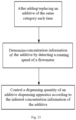
- the control unit of the additive dispensing module or the control unit of the laundry treatment device can determine the concentration information of the additives into the liquid storage module according to the rotating speed acquired of the flowmeter, and further control a dispensing quantity of the additive dispensing module according to the concentration information being determined of the additives.
- a step of determining the concentration information of the additives by detecting the rotating speed of the flowmeter can be executed.
- the concentration information of the additives is determined by detecting the rotating speed of the flowmeter.
- Another purpose of the present disclosure is further to provide an additive dispensing module adopting the above detection method.
- the additive dispensing module is installed outside a laundry treatment device; or the additive dispensing module and the laundry treatment device are independent from each other.
- the present disclosure has the following beneficial effects compared with the prior art.
- a liquid storage box with its own function of recognizing identity information is provided.
- the categories of additives stored in an additive container are identified by a specific concave-convex structure.
- the present disclosure is further to provide an additive dispensing module, which realizes to automatically recognize an identity of the installed liquid storage box, and further recognize the categories of the additives in the liquid storage box.
- the present disclosure further provides a method for recognizing the liquid storage box, which realizes to automatically determine the categories of the additives in the liquid storage box.
- a liquid storage box is internally provided with a sealing cavity for storing an additive, and at least one concave-convex part is arranged on an outer wall of the liquid storage box.
- a combination of the quantity and position of the concave-convex part arranged on the liquid storage box correspondingly represents a category of the additive stored in the liquid storage box.
- a first concave-convex part and a second concave-convex part which are spaced at an interval are arranged on the liquid storage box, and the interval correspondingly represents the category of the additive stored in the liquid storage box.
- the interval includes distance information, relative spatial information and position information arranged on the liquid storage box between the first concave-convex part and the second concave-convex part.
- any one or a combination of the quantity and positions of the concave-convex parts is different on the liquid storage boxes for storing the additives of different categories.
- the concave-convex parts are protrusions protruding outwards from an outer wall of the liquid storage box, or grooves sunk inwards from the outer wall of the liquid storage box.
- the concave-convex parts are formed by the outer wall of the liquid storage box; or the concave-convex parts are formed by separable components installed on the outer wall of the liquid storage box.
- at least part of the outer wall of the liquid storage box is a smooth surface, the smooth surface of the outer wall is provided with parts that are changed in concave and convex in a direction from an interior to outside of the liquid storage box, and the parts with the change in concave and convex form the concave-convex parts.
- all the concave-convex parts have the same shape.
- each concave-convex part is located at the end provided with the liquid outlet of the liquid storage box, or close to the end provided with the liquid outlet.
- all the concave-convex parts are located on the same side of the liquid storage box.
- all of the concave-convex parts are located in the same cross-section of the liquid storage box.
- An additive dispensing module in the present disclosure comprises, at least one accommodating part for installing the above liquid storage box.
- the accommodating part is internally provided with contact switches, each of the contact switches covers contact positions with the concave-convex parts on different liquid storage boxes, and each of the concave-convex parts on the liquid storage boxes is in contact with one contact switch arranged in the accommodating part respectively.
- a recognition unit determines categories of additives in the liquid storage boxes based on information of the contact switches in contact with the concave-convex parts.
- the information of the contact switches in contact with the concave-convex parts includes any one or a combination of the quantity and positions of the contact switches in contact with the concave-convex parts.
- the accommodating parts are divided into a plurality of categories according to different categories of additives to be dispensed. Any one or a combination of the quantity and positions of the contact switches is different in the accommodating parts of different categories.
- a method for recognizing a liquid storage box in the present disclosure includes, inserting the liquid storage box into an accommodating part of an additive dispensing module, wherein the concave-convex parts arranged on the liquid storage box are correspondingly in contact with the contact switches in the accommodating part; acquiring information of the contact switches in contact with the concave-convex parts; and determining the category of the additive in the liquid storage box based on the information of the contact switches in contact with the concave-convex parts.
- the present disclosure further provides a laundry treatment apparatus.
- the laundry treatment apparatus is provided with the above additive dispensing module.
- the recognition method of the above liquid storage box is utilized to recognize the category of the additive in a liquid storage box installed in the additive dispensing module.
- the present disclosure has the following beneficial effects compared with the prior art.
- a plurality of concave-convex parts exposed on the outer wall are arranged on the liquid storage box.
- the category of the additive in the liquid storage box are accurately identified by using any one or a combination of information such as the quantity, relative positions and positions of the concave-convex parts on the liquid storage box, so that significant progress in clearly identifying category information of the additives in different liquid storage boxes is achieved.
- the concave-convex parts installed on the liquid storage boxes with different quantities and/or positions are all in contact with the contact switches arranged on the additive dispensing module, so that the different detection signals are formed on the contact switches with different quantities and different positions in the dispensing module in which the liquid storage boxes are arranged .
- the category information of the additives is identified by recognizing the concave-convex parts arranged on the liquid storage boxes.
- the identity of the liquid storage box may be accurately recognized by the contact information of the contact switches, which may realize the significant progress in automatic and accurate recognition of the categories of the additives.
- a liquid storage box is internally provided with a sealing cavity for storing an additive. At least two conductive contact pieces being in contact with the additive in the sealing cavity are arranged on an outer wall of the liquid storage box, and a combination of the quantity and positions of the conductive contact pieces arranged on the liquid storage box correspondingly represents a category of the additive stored in the liquid storage box.
- first conductive contact piece and a second conductive contact piece which are spaced at an interval, are arranged on the liquid storage box, and the interval correspondingly represents the category of the additive in the liquid storage box.
- the interval correspondingly represents the category of the additive in the liquid storage box.
- the interval includes distance information, relative spatial information and position information between the first conductive contact piece and the second conductive contact piece on the liquid storage box.
- each of the liquid storage boxes for storing the additives of different categories is provided with the first conductive contact piece, and the first conductive contact piece is arranged at common set positions on the liquid storage boxes.
- the liquid storage boxes for storing the additives of different categories have the same shape.
- the liquid storage box is provided with conductive probes being extended into the sealing cavity.
- the conductive contact pieces exposed out of the outer wall of the liquid storage box are connected with the conductive probes, and the conductive contact pieces are conducted with the additive in the sealing cavity through the conductive probes.
- one ends of the conductive probes are connected with the liquid storage box, and the other ends of the conductive probes are extended into the sealing cavity.
- the one ends, connected with the liquid storage box, of the conductive probes form the conductive contact pieces.
- the contact pieces independently arranged on the liquid storage box and in contact with the conductive probes form the conductive contact pieces.
- a liquid outlet is formed in one end of the liquid storage box, and each conductive contact piece is located at the one end provided with the liquid outlet of the liquid storage box, or close to the one end provided with the liquid outlet.
- two sides of the liquid storage box in a vertical direction are as a top wall and a bottom wall, and other sides of the liquid storage box are peripheral walls. All the conductive contact pieces are located on the bottom wall of the liquid storage box, and the conductive probes are extended upwards from the bottom wall of the liquid storage box vertically. Or, all the conductive contact pieces are located on the top wall of the liquid storage box, and the conductive probes are extended downwards from the top wall of the liquid storage box vertically.
- each of the conductive probes is extended in the vertical direction in the liquid storage box, and an upper end or lower end is connected with the corresponding conductive contact piece through a horizontal section. More preferably, an extension end of each of the conductive probes is at the same height.
- the present disclosure further provides an additive dispensing module, which is provided with at least one accommodating part for installing the above liquid storage box.
- the accommodating part is internally provided with a plurality of conductive contact terminals.
- the conductive contact terminals cover contact positions of the conductive contact pieces on different liquid storage boxes, and each of the conductive contact pieces arranged on the liquid storage boxes is in contact with one conductive contact terminal arranged in the accommodating part respectively.
- a recognition unit determines categories of additives in the liquid storage boxes based on information of the conductive contact terminals in contact with the conductive contact pieces.
- the accommodating part is internally provided with a common set detection position.
- the conductive contact terminal arranged at the common set detection position is in contact with a first conductive contact piece at a common set position of the liquid storage box, and the conductive contact terminal at the common detection position is connected with other conductive contact terminals through a detection circuit respectively.
- the accommodating parts are divided into a plurality of categories according to different categories of additives to be dispensed. Any one or a combination of the quantity and position of the conductive contact terminals arranged in the accommodating parts of different categories is different.
- the present disclosure further provides a method for recognizing a liquid storage box, including, inserting the liquid storage box into an accommodating part of an additive dispensing module, wherein the conductive contact pieces arranged on the liquid storage box are correspondingly in contact with the conductive contact terminals in the accommodating part; acquiring information of the conductive contact terminals connected with the conductive contact pieces; and determining category of additive in the liquid storage box based on the information of the conductive contact terminals connected with the conductive contact pieces.
- a laundry treatment apparatus in the present disclosure is provided with the above additive dispensing module.
- the method for recognizing the above liquid storage box is utilized to recognize the category of additive in a liquid storage box installed on the arranged additive dispensing module.
- the present disclosure has the following beneficial effects by adopting the above technical solutions.
- a plurality of conductive contact pieces exposed on the outer wall are arranged on the liquid storage box.
- the category of the additive contained in the liquid storage box is accurately identified by using any one or a combination of information such as the quantity, relative positions and positions on the liquid storage box of the conductive contact pieces, so that the categories of the additives are clearly identified in different liquid storage boxes.
- the structures of the device of are simple, the method is concise and the effects are significant, so it is suitable for promotion and use.
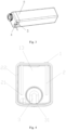
- Dispensing module 2. Liquid storage box; 3. Accommodating part; 4. Conductive contact piece; 5. Conductive contact terminal; 6. Conductive probe; 7. Sealing cavity; 8. Liquid outlet; 4'. Concave-convex part; 5'. Contact switch; 101. Upper cover; 21. Top wall; 22. Bottom wall; 23. Peripheral wall; 61. Vertical section; 62. Horizontal section; 63. Liquid level detection end; 41. First conductive contact piece; 42. Second conductive contact piece; 41'. First concave-convex part; 42'. Second concave-convex part; 03. Liquid guide interface structure; and 031. Inlet end.
- connection may be fixed connection or detachable connection or integrated connection, may be mechanical connection or electric connection, and may be direct connection or indirect connection through an intermediate medium.
- connection may be fixed connection or detachable connection or integrated connection, may be mechanical connection or electric connection, and may be direct connection or indirect connection through an intermediate medium.
- the embodiment describes a liquid storage box 2.
- the liquid storage box 2 is internally provided with a sealing cavity for storing an additive, and the cavity inside the liquid storage box 2 in the embodiment is an independent sealed liquid storage cavity.
- the liquid storage box 2 is further provided with a conductive detection part being capable of detecting liquid level information of the additive in the liquid storage box, and the conductive detection part is as a part of the liquid storage box 2.
- the liquid storage box 2 in the embodiment has higher integrity, independent usability and reliability compared to a liquid storage box in the prior art.
- the liquid storage box 2 itself in the embodiment is provided with the conductive detection part being capable of detecting the liquid level information of the additive in the liquid storage box, which solves the existing problems that assembly between the liquid storage box 2 and conductive probes 6 is complex, additive leakage is prone to occurring due to poor sealing, and the liquid storage box 2 cannot continue to be used after the conductive probes 6 are removed.
- the conductive detection part and the liquid storage box 2 are of an integrated structure.
- the conductive detection part is integrally formed in the liquid storage box 2 through a specific processing technology.
- the conductive detection part and the liquid storage box 2 are of the integrated structure, there is no need to further assemble and install the conductive detection part and the liquid storage box , so assembly steps are simplified.
- the conductive detection part and the liquid storage box 2 are of the integrated structure, there is no problem of additive leakage due to poor sealing between both of them, and the reliability of the liquid storage box 2 is ensured.
- the conductive detection part is a partial structure of the liquid storage box 2, and a part of the box body of the liquid storage box 2 is made of a metal conductive material to form the conductive detection part. So the conductive detection part is the partial structure of the liquid storage box 2, and the integrity of the liquid storage box 2 is improved.
- the conductive detection part is at least two conductive probes 6 integrally formed in the liquid storage box 2.
- the conductive detection part is two conductive probes 6 is taken as an example for detailed description.
- the conductive detection part may also be three conductive probes 6, four conductive probes 6 and the like.
- each of the conductive probes 6 is as a liquid level detection end 63 being extended into the additive of the liquid storage box 2 and used for detecting a liquid level.
- the liquid level detection ends 63 may detect the liquid level information of the additive,.
- the other end of each of the conductive probes 6 are provided with a conductive contact piece 4 being in contact and electrical connection with an external circuit. When the liquid storage box 2 is placed into a dispensing module 1, the conductive contact pieces 4 may be connected with the external circuit.
- a lower end of each of the conductive probes 6 is the liquid level detection end 63, and an upper end of each of the conductive probes 6 is provided with the conductive contact piece 4 with an increased outer diameter.
- the conductive contact piece 4 is exposed outside the liquid storage box 2, so that, the liquid storage box 2 may be connected with a detection circuit when being placed into the dispensing module 1, and further the liquid level information of the additive in the liquid storage box 2 is detected.
- the conductive contact piece 4 is protruded from an outer wall surface of the liquid storage box 2.
- the conductive contact piece 4 may be set to be of a square or strip-shaped structure with a certain thickness.
- the conductive contact piece 4 may be outside of the outer wall surface of the liquid storage box 2. Or, part of the conductive contact piece 4 may also be embedded into the liquid storage box 2 and the other part is outside of the liquid storage box 2.
- the conductive contact piece 4 is embedded into the box body of the liquid storage box 2, and the top wall of the conductive contact piece 4 is set to be flush with the outer wall surface of the liquid storage box 2.
- the two conductive probes 6 are arranged at intervals, and the liquid level detection ends 63 of the conductive probes 6 are extended into a lower of the liquid storage box 2 and higher than a bottom wall 22 of the liquid storage box 2.
- a distance between the liquid level detection ends 63 of the conductive probes 6 and the bottom wall 22 of the liquid storage box 2 may be adjusted according to the actual demands for liquid level detection. The higher the detected liquid level is, the larger the distance between the liquid level detection ends 63 of the conductive probes 6 and the bottom wall 22 of the liquid storage box 2 is.
- a plurality of sets of conductive probes 6 may be arranged in the liquid storage box 2. Distances between different sets of conductive probes 6 and the bottom wall 22 of the liquid storage box 2 are different for detecting different liquid levels in the liquid storage box 2.
- an overall height of the liquid storage box 2 is set as L, and three sets of conductive probes 6 are arranged in the liquid storage box 2.
- a distance between the first set of conductive probes 6 and the bottom wall 22 of the liquid storage box 2 is 1/a L
- a distance between the second set of conductive probes 6 and the bottom wall 22 of the liquid storage box 2 is 1/b L
- a distance between the third set of conductive probes 6 and the bottom wall 22 of the liquid storage box 2 is 1/c L
- a, b and c are integers greater than 1, a>b>c.
- values of a, b and c may be set according to detection demands.
- a detection circuit between the two liquid level detection ends 63 of the first set of conductive probes 6 is disconnected.
- the detection circuit corresponding to the first set of conductive probes 6 cannot detect a current, or can detect the current becoming relatively weak.
- a signal is fed back to a control unit of the dispensing module 1, and the control unit sends a prompt signal to a user that the liquid level of the additive in the liquid storage box 2 is dropped to 1/a L.
- the detection circuit corresponding to the second set of conductive probes 6 cannot detect the current, or can detect the current becoming relatively weak.
- the control unit sends a prompt signal to the user that the liquid level of the additive in the liquid storage box 2 is dropped to 1/b L.
- the detection circuit corresponding to the third set of conductive probes 6 cannot detect the current, or can detect the current becoming relatively weak.
- the control unit sends a prompt signal to the user that the liquid level of the additive in the liquid storage box 2 is dropped to 1/c L.
- the control unit sends an alarm signal to the user, prompting the user that the residual of the additive in the liquid storage box 2 is insufficient, and the liquid storage box 2 is replaced timely.
- prompts may be sent to the user in stages according to the decrease in the liquid level in the liquid storage box 2, so that the user can have more sufficient time to prepare and better use experience.
- a display module is further arranged on the dispensing module.
- the control unit synchronously feeds the liquid level information of the additive in the liquid storage box 2 detected by the first set of conductive probes 6, the second set of conductive probes 6 and the third set of conductive probes 6 back to the display module for displaying, which provides the user with a more direct reference.
- a liquid outlet is formed in the liquid storage box 2, and a liquid guide interface structure 03 for guiding the additive in the liquid storage box 2 into a dispensing unit is installed at the liquid outlet.
- the liquid guide interface structure 03 is internally provided with a liquid guide channel with an inlet end 031 communicating with the sealing cavity inside the liquid storage box 2.
- the liquid level detection ends 63 of the conductive probes 6 are not lower than the inlet end 031 of the liquid guide interface structure 03.
- the inlet end 031 of the liquid guide interface structure 03 is extended downwards to a bottom wall 22 of the liquid storage box 2, so as to ensure that the additive in the liquid storage box 2 can be completely sucked out.
- An outlet end of the liquid guide interface structure 03 is communicated with the dispensing unit of the dispensing module 1.
- prompt information is sent to the user when the liquid level in the liquid storage box 2 is dropped to the position of the inlet end 031 of the liquid guide interface structure 03. It is effectively avoided that the dispensing unit cannot suck the additive in the liquid storage box 2.
- the conductive probes 6 and the liquid storage box 2 are of an integrated structure formed by a melting, hot-pressing, hot-riveting, and/or bonding process.
- the connection between the conductive probes 6 and the liquid storage box 2 is not limited to use the above processes for integrated forming.
- the conductive probes 6 may be embedded into or attached to an inner wall side of the liquid storage box 2. Or the conductive probes 6 are arranged in a middle of the liquid storage box 2 in an embedded mode, and the conductive probes 6 are as a part of the liquid storage box 2, which ensures the integrity of the liquid storage box 2.
- the conductive probes 6 are parts of the liquid storage box 2.
- the liquid storage box 2 includes a bottom wall 22 and a top wall 21, as well as a peripheral wall 23 connected between the top wall 21 and the bottom wall 22.
- Parts of the peripheral wall 23 is made of a metal conductive material to form the conductive detection part, and the conductive detection part is two conductive probes 6 being strip shape, extending from the top wall 21 of the liquid storage box 2 to the bottom of the liquid storage box 2, and matched with the liquid storage box 2 in shape.
- outer wall surfaces of the conductive probes 6 are flush with an outer wall surface of the liquid storage box 2, inner wall surfaces of the conductive probes 6 are protruded from an inner wall surface of the liquid storage box 2.
- Upper end surfaces of the conductive probes 6 are extended out of the top wall 21 of the liquid storage box 2, or may also be arranged to be flush with the top wall 21 of the liquid storage box 2, and lower end parts of the conductive probes 6 are extended to a position close to the bottom wall 22 of the liquid storage box 2.
- two conductive probes 6 are arranged on the peripheral wall of the same side of the liquid storage box 2 at intervals. That is, two parts spaced on the peripheral wall of the same side of the liquid storage box 2 are made of the metal conductive materials respectively to form the conductive probes 6.
- the conductive probes 6 are respectively arranged on two adjacent peripheral walls of the liquid storage box 2. That is, each of the two adjacent side walls of the liquid storage box 2 is provided with the part made of the metal conductive materials to form the conductive probes 6.
- two conductive probes 6 are respectively arranged on two opposite peripheral walls of the liquid storage box 2. That is, each of the two opposite side walls of the liquid storage box 2 is provided with the part made of the metal conductive materials, to form the conductive probes 6.
- the liquid storage box 2 itself in the embodiment has a function of detecting the liquid level information of the additive in the liquid storage box, and the conductive detection part is integrally formed on the liquid storage box 2.
- a part of the box body of the liquid storage box 2 is made of the conductive material to form the conductive detection part, so that the conductive detection part and the liquid storage box 2 are of the integrated structure. So the existing problems are solved that assembly between the liquid storage box 2 and the conductive probes 6 is complex, additive leakage is prone to occurring due to poor sealing, and the liquid storage box 2 cannot continue to be used after the conductive probes 6 are removed.
- the embodiment further provides a dispensing module 1 with the above liquid storage box 2.
- a liquid level detection module is arranged on the dispensing module 1, and the liquid level detection module is provided with conductive contact terminals 5 corresponding to the conductive contact pieces 4 of the two conductive probes 6.
- the conductive contact terminals 5 of the liquid level detection module are in contact and electrically connected with the conductive contact pieces 4 of the conductive detection part.
- the liquid level information of the additive in the liquid storage box 2 is judged through a feedback signal outputted by the liquid level detection module.
- the dispensing module 1 is provided with an accommodating part for placing the liquid storage box 2.
- the liquid level detection module is provided with the conductive contact terminals 5 corresponding to the conductive contact pieces 4 of the two conductive probes 6.
- the liquid level detection module is internally provided with a detection circuit.
- the detection circuit may be any existing circuit structure. It needs to be ensured that the circuit structure has two ends, the two ends are respectively connected with different conductive contact terminals 5.
- a high-level signal can be sent.
- a low-level signal can be sent. So different signals can be sent respectively, when the detection circuit is conducted to form the loop and disconnected not to form the loop.
- the conductive contact pieces 4 of the two conductive probes 6 are in contact with the conductive contact terminals 5 respectively to conduct the liquid level detection module.
- the conductive contact pieces 4 of the two conductive probes 6 are separated from the conductive contact terminals 5, so a detection loop between the liquid level detection module and the conductive probes 6 is disconnected.
- the detection loop between the liquid level detection module and the two conductive probes 6 is conducted.
- the liquid level detection module can output a high-level signal and detect that there are sufficient additives in the liquid storage box 2.
- the liquid level detection module can output a low-level signal, then it is detected that the liquid level of the additive in the liquid storage box 2 is lower than a set value, and the user is prompted to replace the liquid storage box 2 timely.
- the dispensing module 1 is arranged on a water inlet pipeline connected between a laundry treatment device and a tap water joint.
- the dispensing module 1 includes an upper cover 101 located above the accommodating part, and the conductive contact terminals 5 may be arranged on the upper cover 101.
- Spring contact pieces are arranged at the ends of the conductive contact terminals 5. After the user installs the liquid storage box 2 in the accommodating part of the dispensing module 1, the spring contact pieces of the conductive contact terminals 5 arranged on the upper cover 101 is in contact with the liquid level detection ends 63 of the conductive probes 6 on the liquid storage box 2, so as to detect the liquid level.
- the conductive contact terminals 5 are fixedly arranged on the upper cover 101 located at a top of the liquid storage box 2, and a water way is integrated on the upper cover 101.
- the conductive contact terminals 5 may also be arranged at other positions of the dispensing module 1, and the conductive contact pieces 4 of the liquid storage box 2 can be in tight contact with the conductive contact terminals 5 once the liquid storage box 2 is placed in the accommodating part.
- the embodiment further provides a laundry treatment device.
- the above dispensing module is arranged on the water inlet pipeline between the laundry treatment device and the tap water joint.
- An external dispensing module 1 is adopted in the embodiment.
- the dispensing module 1 and the laundry treatment device are respectively provided with an independent control system.
- the dispensing module 1 is arranged on the water inlet pipeline between the tap water joint and a water inlet valve of the laundry treatment device.
- the laundry treatment device is a washing machine or a washing and drying integrated machine.
- the dispensing module 1 includes a liquid storage module being communicated with the laundry treatment device via a dispensing pipeline, and a dispensing unit arranged on the dispensing pipeline and used for dispensing an additive to the laundry treatment device.
- the above liquid storage box 2 is arranged in the liquid storage module.
- the dispensing module 1 is arranged in the water inlet pipeline connected between the tap water joint and the water inlet valve of the laundry treatment device. Two ends of the dispensing pipeline are communicated with the liquid storage box 2 and the water inlet pipeline respectively.
- the dispensing unit includes a dispensing pump or a Venturi tube, which is used for dispensing the additive to the water inlet pipeline.
- the water inlet valve of the laundry treatment device In supplying water into the laundry treatment device, the water inlet valve of the laundry treatment device is opened, and water from the tap water joint passes through the water inlet pipeline.
- the additive in the liquid storage box 2 is dispensed to the water inlet pipeline by the dispensing unit, so that the additive is fed in the laundry treatment device along with water in the water inlet pipeline.
- the dispensing module 1 in the embodiment may be installed outside the laundry treatment device. That is, the dispensing module 1 is installed on the laundry treatment device and located outside the laundry treatment device. For example, the dispensing module 1 may be fixedly installed on an outer wall of a shell of the laundry treatment device.
- the dispensing module 1 and the laundry treatment device are independent from each other. There is no assembly connection relationship between the dispensing module 1 and the laundry treatment device, which are two sets of devices independent of each other. In this way, the position for installing the dispensing module 1 is relatively not limited, and any position is feasible as long as the dispensing module 1 can be communicated with the water inlet pipeline between the washing machine and the tap water joint, and the additive can be dispensed into the washing machine along with the entering water of the water inlet pipeline.
- the embodiment describes a liquid storage box on basis of Embodiment 1.
- the liquid storage box 2 is internally provided with a sealing cavity for storing an additive.
- At least two conductive contact pieces 4 in contact with the additive in the sealing cavity are arranged on an outer wall of the liquid storage box 2.
- a combination of the quantity and positions of the conductive contact pieces 4 arranged on the liquid storage box 2 correspondingly represents a category of the additive stored in the liquid storage box 2.
- a plurality of conductive contact pieces 4 exposed on the outer wall are arranged on the liquid storage box 2.
- the categories of the additives in the liquid storage box 2 are accurately identified by using any one or a combination of information such as the quantity, relative positions and positions on the liquid storage box 2, of the conductive contact pieces 4. Significant progress is achieved in clearly identifying category information of the additives in different liquid storage boxes 2.
- the embodiment describes a liquid storage box.
- the liquid storage box 2 is internally provided with a sealing cavity for storing an additive.
- a first conductive contact piece 41 and a second conductive contact piece 42 which are spaced at an interval, are arranged on an outer wall of the liquid storage box 2, and the interval between the first conductive contact piece 41 and the second conductive contact piece 42 correspondingly represents a category of the additive stored in the liquid storage box 2.
- the liquid storage boxes 2 there are a plurality of types of liquid storage boxes 2, and the liquid storage boxes 2 correspondingly contain the additives of different categories, such as a detergent, an odorant, a softener and a disinfectant.
- the additives of different categories may be correspondingly dispensed, and the laundry treatment apparatus correspondingly executes the different washing programs of different and treat laundry by using the additives of different categories.
- the liquid storage boxes 2 of the additive dispensing module may further store detergents with different concentrations respectively, such as super concentrated, concentrated, ordinary and low foam.
- the laundry treatment apparatus executes different washing programs to wash different pieces of laundry by correspondingly dispensing the detergents of corresponding categories. So the purpose of improving a washing effect of the laundry treatment apparatus is achieved.
- the interval includes distance between the first conductive contact piece 41 and the second conductive contact piece 42, relative spatial orientation of the first conductive contact piece 41 and the second conductive contact piece 42, and position arranged on the liquid storage box 2.
- a distance between the first conductive contact piece 41 and the second conductive contact piece 42 arranged on a detergent liquid storage box 2 for containing a detergent is 1 cm
- a distance between the first conductive contact piece 41 and the second conductive contact piece 42 arranged on a bleach liquid storage box 2 for containing a bleach is 2 cm.
- the first conductive contact piece 41 on the detergent liquid storage box 2 for containing the detergent is located above the second conductive contact piece 42 by 1 cm, and the first conductive contact piece 41 on the bleach liquid storage box 2 for containing the bleach is located on the left of the second conductive contact piece 42 by 1 cm.
- the first conductive contact piece 41 on the detergent liquid storage box 2 for containing the detergent is located on the left of the second conductive contact piece 42 by 2 cm, and the first conductive contact piece 41 on the bleach liquid storage box 2 for containing the bleach is located above the second conductive contact piece 42 by 1 cm, and so on.
- the first conductive contact pieces 41 are arranged on the liquid storage boxes 2 for storing the additives of different categories respectively.
- the first conductive contact pieces 41 are arranged at the common set identification position on the liquid storage boxes 2, and the second conductive contact pieces 42 are arranged at different positions.
- the intervals between the first conductive contact pieces 41 and the second conductive contact pieces 42 on different liquid storage boxes are changeably, so the liquid storage boxes for storing the additives of different categories are correspondingly identified.
- the liquid storage box 2 may be configured to be of a structure with any shape, such as a square cylindrical shape, a spherical shape and an elliptical spherical shape.
- the liquid storage box 2 in the embodiment is configured as a basic square cylindrical shape.
- a liquid outlet is formed in one end of the liquid storage box 2 in the basic square cylindrical shape.
- a container connection element is generally installed at the liquid outlet, the container connection element generally closes the liquid outlet in a common state.
- the liquid outlet When the liquid storage box 2 is installed into the accommodating part of the additive dispensing module, the liquid outlet may be opened under the action of a liquid guide connection element and other components.
- the container connection part may also be configured as any other existing structures which can close the liquid outlet of the liquid storage box.
- the specific arrangement of the container connection element and the liquid guide connection element may be as follows.
- the liquid guide connection element arranged in the accommodating part of the additive dispensing module is of a rod extending in a pull direction of the liquid storage box.
- the container connection element arranged at the liquid outlet of the liquid storage box is of a sleeve structure extending into the accommodating part in the pull direction of the liquid storage box.
- a valve body is arranged at one end of the sleeve structure, and the other end of the sleeve structure is communicated with an interior of the liquid storage box through the liquid outlet.
- a spring in a compressed state is arranged in the sleeve structure, and two ends of the spring respectively abut against the valve body and the sleeve structure.
- the valve body abuts against one end, facing inwards the accommodating part, of the sleeve structure under an elastic effect of the spring, to close a channel formed in the sleeve structure. So the liquid outlet of the liquid storage box is closed, and a sealed container is formed in the liquid storage box.
- the liquid guide connection element is in contact with the valve body and drives the valve body to move towards the interior of the liquid storage box against an elastic force applied by the spring. In this way, the liquid outlet of the liquid storage box is opened and the additives are dispensed.
- intervals between the first conductive contact pieces 41 of the liquid storage boxes for storing the additives of different categories and the liquid outlets of the liquid storage boxes 2 are the same, so that relative positions of the conductive contact pieces 4 on the additive dispensing module 1 remain constant after the liquid storage boxes 2 are installed, and further the category information of additive is accurately acquired by the additive dispensing module 1 on basis of the conductive contact pieces 4 arranged on the liquid storage boxes 2. More preferably, in order to further ensure the accuracy of acquiring information, the liquid storage boxes 2 for storing the additives of different categories have the same shapes.
- the liquid storage box 2 is provided with a position correcting structure for installing the liquid storage box at the same position, and the position correcting structure may be designed by using the shape of the liquid storage box 2 itself, a concave-convex structure arranged on an outer surface and the like (not shown in the figure).
- Embodiment 2 based on the above Embodiment 1 and Embodiment 2, further has the following technical features.
- the embodiment describes a liquid storage box.
- the liquid storage box 2 is internally provided with a sealing cavity for storing an additive, at least two conductive contact pieces 4 are arranged on an outer surface of the liquid storage box 2, and every two conductive contact pieces 4 are spaced at an interval. All conductive contact pieces 4 are distributed at different positions of the liquid storage box 2 in a mode that the positions are changeable.
- a combination of the quantity and positions of the conductive contact pieces 4 on the liquid storage box 2 correspondingly represents the category of the additive stored in the liquid storage box.
- the quantity information of the conductive contact pieces 4 is the quantity of the conductive contact pieces 4 arranged on the outer surface of the liquid storage box 2, as follows.
- two conductive contact pieces 4 are arranged on the liquid storage box 2 for containing a detergent.
- Three conductive contact pieces 4 are arranged on the liquid storage box 2 for containing a bleach.
- Four conductive contact pieces 4 are arranged on the liquid storage box for containing a disinfectant.
- the position information of the conductive contact pieces 4 includes distance information, relative spatial orientation information and position information on the liquid storage box among the conductive contact pieces 4.
- the conductive contact pieces 4 are arranged at a position a, a position b and a position c on the liquid storage box 2 for containing the detergent respectively.
- the conductive contact pieces 4 are arranged at a position a, a position b and a position d on the liquid storage box 2 for containing the bleach respectively.
- the conductive contact pieces 4 are arranged at a position a, a position c and a position d on the liquid storage box 2 for containing the disinfectant respectively.
- the quantity information and the position information of the conductive contact pieces 4 may further be correspondingly combined, so as to correspond more categories of additive.
- the conductive contact pieces 4 are arranged at a position a, a position b, a position c and a position d on the liquid storage box 2 for containing a concentrated detergent respectively, the conductive contact pieces 4 are arranged at a position a, a position b and a position c on the liquid storage box 2 for containing an ordinary detergent respectively, and the conductive contact pieces 4 are arranged at a position a, a position b, a position c and a position e on the liquid storage box 2 for containing a low-foam detergent respectively.
- the conductive probes 6 extending into the sealing cavity are arranged on the liquid storage box 2, and the conductive contact pieces 4 exposed on an outer surface of the liquid storage box 2 are connected with the conductive probes 6.
- the conductive contact pieces 4 are conducted with the additive contained in the sealing cavity through the conductive probes 6.
- the conductive probes 6 are installed on the liquid storage box 2, one ends of the conductive probes 6 are connected with the liquid storage box 2, and the other ends of the conductive probes 6 are extended into the sealing cavity.
- the conductive probes 6 and the conductive contact pieces 4 may be arranged integrally.
- the end, connected with the liquid storage box, of the conductive probe 6 directly forms the conductive contact piece 4.
- the conductive probe 6 is connected with the conductive contact piece 4.
- the contact piece is independently arranged on the liquid storage box 2 and in contact with the conductive probes 6 to form the conductive contact piece 4.
- the liquid storage box 2 with identifiers of the conductive contact pieces 4 may be set into a same shape.
- the liquid storage boxes 2 for storing additives of different categories have the same shapes, so as to easily replace the liquid storage boxes 2.
- two sides of the liquid storage box 2 in an up-down vertical direction are a top wall 21 and a bottom wall 22 respectively, and other sides of the liquid storage box 2 are all peripheral walls 23.
- each conductive contact piece 4 is located on the top wall 21 of the liquid storage box 2, and each conductive probe 6 is extended downwards and vertically from the top wall 21 of the liquid storage box 2.
- an electric conductivity of a loop formed between the conductive probes 6 is detected in changing a liquid level height of the additive in the liquid storage box 2, so the liquid level of the additive in the liquid storage box 2 is detected.
- each conductive contact piece 4 may further be located on the bottom wall 22 of the liquid storage box 2.
- Each conductive probe 6 is extended upwards and vertically from the bottom wall 22 of the liquid storage box 2.
- each conductive contact piece 4 is further located on the peripheral wall of the liquid storage box 2.
- Each conductive probe 6 includes a horizontal section 62 and a vertical section 61 being perpendicular to and connected to an end part of one side of the horizontal section 62.
- One end of the horizontal section 62 is exposed on the peripheral wall 23 of the liquid storage box 2 to directly form the conductive contact piece 4, or to be connected with the conductive contact piece 4 arranged on the liquid storage box 2.
- the other end of the horizontal section 62 is located in the liquid storage box 2 to be connected with an upper end part of the vertical section 61.
- the lower end of the vertical section 61 is extended downwards and is above the bottom wall 22 of the liquid storage box 2.
- the lower end of the vertical section 61 is in contact with the additive in the sealing cavity 7 of the liquid storage box 2, and the electric conductivity of the loop formed between the conductive probes 6 may be detected when the liquid level of the additive in the liquid storage box 2 changes, and thus the liquid level of the additive in the liquid storage box 2 is detected.
- the other end of the horizontal section 62 may be connected with the lower end of the vertical section 61, and the upper end is extended upwards and is a position below the top wall 21, so the same purpose may be realized.
- the horizontal section 62 and the liquid storage box 2 are of an integrated structure formed by a melting, hot-pressing, hot-riveting and/or bonding process, so as to realize the fixed installation between the conductive probes 6 and the liquid storage box 2.
- the lower end of the vertical section 61 is lower than or equal to a minimum liquid level of the liquid storage box 2, and an upper end of the vertical section 61 is higher than or equal to a maximum liquid level of the liquid storage box 2.
- the liquid storage box 2 may further be vertically placed.
- each conductive contact piece 4 is located on the bottom wall 22 of the liquid storage box 2, and each conductive probe 6 is extended upwards and vertically from the bottom wall 22 of the liquid storage box 2.
- the electric conductivity of the loop formed between the conductive probes 6 is detected when the liquid level of the additive in the liquid storage box 2 changes, and further the liquid level of the additive in the liquid storage box 2 is detected.
- the height, upward extended, of the conductive probes 6 in the liquid storage box 2 is greater than or equal to the liquid level of the liquid storage box 2 in no-load state, so as to realize effectively to detect the identity of the liquid storage box 2.
- each of the conductive contact pieces 4 is located on the peripheral wall of the liquid storage box 2.
- Each of the conductive probes 6 includes the horizontal section 62 and the vertical section 61 is perpendicular to and connected to the end part of one side of the horizontal section 62.
- One end of the horizontal section 62 is exposed on the peripheral wall 23 of the liquid storage box 2 to form the conductive contact piece 4.
- one end of the horizontal section 62 is connected with the conductive contact piece 4 arranged on the liquid storage box 2, the other end of the horizontal section 62 is located in the liquid storage box 2 and connected with a lower end part of the vertical section 61.
- the upper end of the vertical section 61 is extended upwards and is in a position above the top wall 21 of the liquid storage box 2, so as to be in contact with the additive in the sealing cavity 7 of the liquid storage box 2.
- the horizontal section 62 is lower than the liquid level of the liquid storage box 2 being in no-load state
- the vertical section 61 is higher than the liquid level of the liquid storage box 2 being in no-load state. So the electric conductivity of the loop formed between the conductive probes 6 is detected when the liquid level of the additive in the liquid storage box 2 changes, and thus the liquid level of the additive in the liquid storage box 2 is detected.
- the conductive contact pieces 4 are arranged on the side of the liquid storage box 2 provided with the liquid outlet, or close to the liquid outlet. After the liquid storage box 2 is installed, the conductive contact pieces 4 may be located in the additive dispensing module 1, and the connection between the conductive contact pieces 4 and the conductive contact terminals 5 arranged in the additive dispensing module 1 is facilitated.
- the embodiment describes an additive dispensing module comprising the liquid storage box in the above embodiments.
- the additive dispensing module 1 is provided with at least one accommodating part for installing the above liquid storage box 2.
- the accommodating part is internally provided with a plurality of conductive contact terminals 5, and each of the conductive contact terminals 5 covers the position where the conductive contact piece 4 arranged on different liquid storage boxes 2 can be in contact, so each of the conductive contact pieces 4 arranged on the liquid storage boxes 2 are in contact with one conductive contact terminal 5 arranged in the accommodating part respectively.
- the embodiment further describes a method for recognizing a liquid storage box installed in the above additive dispensing module, including: a liquid storage box 2 being inserted into an accommodating part of an additive dispensing module 1, each of the conductive contact pieces 4 arranged on the liquid storage box 2 being correspondingly in contact with the conductive contact terminal 5 in the accommodating part; acquiring information of the conductive contact terminals 5 connected with the conductive contact pieces 4; and determining categories of additives in the liquid storage box 2 based on the information of the conductive contact terminals 5 connected with the conductive contact pieces 4.
- an identity of the liquid storage box 2 being installed may be accurately recognized according to contact information of the conductive contact terminals 5, which may realize to automatically and accurately recognize the categories of the additives.
- the information of the conductive contact terminals 5 connected with the conductive contact pieces 4 includes any one or a combination of the quantity and positions of the conductive contact terminals 5 connected with the conductive contact pieces 4.
- a recognition unit is integrated on or independently arranged outside the additive dispensing module 1.
- the recognition unit may acquire the information of the conductive contact terminals 5 connected with the conductive contact pieces 4, and compare the acquired information of the conductive contact terminals 5 connected with the conductive contact pieces 4 with a prestored database to obtain category information of the additives in the liquid storage box corresponding to the acquired information of the conductive contact terminals 5 connected with the conductive contact pieces 4. It is realized to accurately judge the categories of the additives in the liquid storage box.
- the recognition module may be directly arranged in the additive dispensing module 1, or may be arranged on a laundry treatment apparatus on which the additive dispensing module 1 is installed, or may be arranged on a cloud server, a mobile terminal and other intelligent terminals being in communication connection with the additive dispensing module 1.
- each of the conductive contact pieces 4 on the liquid storage box 2 is in contact with one conductive contact terminal 5 in the accommodating part.
- the following arrangements on the liquid storage boxes 2 and/or the accommodating part are made, so that after the liquid storage box 2 is installed in the accommodating part according to the set position, the conductive contact pieces 4 of the liquid storage box 2 are in contact with the conductive contact terminals 5, and an unique information is acquired according to the conductive contact pieces 4 and conductive contact terminals 5 being conducted with each other.
- intervals between first conductive contact pieces 41 of the liquid storage boxes 2 for storing the additives of different categories and liquid outlets of the liquid storage boxes 2 are the same, so that positions of the conductive contact pieces 4 on the additive dispensing module 1 are constant after the liquid storage boxes 2 are correspondingly installed, further the information about the additive category acquired by the additive dispensing module 1 is accurate according to the conductive contact pieces 4 arranged on the liquid storage boxes. More preferably, in order to further ensure the accuracy of the information, the liquid storage boxes 2 for storing the additives of different categories have the same shape. Most preferably, the liquid storage box 2 is provided with a position correcting structure for installing the liquid storage boxes on a unique position.
- the position correcting structure may be arranged by utilizing the shape of the liquid storage box 2 itself, a concave-convex structure arranged on an outer surface and the like, so that the liquid storage box 2 can only be assembled into the accommodating part of the additive dispensing module 1 in the unique position under an action of the position correcting structure.
- the recognition module in order to recognizing the different liquid storage boxes 2 after being installed, the recognition module may be set as follows.
- the accommodating part is internally provided with a common detection position, and the conductive contact terminal 5 at the common detection position is connected with the other conductive contact terminals 5 through a detection circuit respectively.
- the conductive contact terminal 5 arranged at the common detection position is in contact with the first conductive contact piece 41 arranged at a common identification position of the liquid storage box 2.
- the first conductive contact piece 41 installed on each of the liquid storage boxes 2 may be in contact with the conductive contact terminals 5 at the common detection position, and the other conductive contact pieces 4 arranged on different liquid storage boxes 2 are in contact with the conductive contact terminals 5 at the corresponding positions to be communicating the corresponding detection circuits. So a loop is formed by communicating the detection circuits containing the conductive contact pieces with different quantities and different positions after different liquid storage boxes 2 are arranged in the dispensing module, further to recognize the identity of the conductive contact pieces 4 arranged on the liquid storage boxes 2.
- the detection circuit may be any existing circuit structure. It needs to ensure that the circuit structure has two ends, and the two ends are respectively connected with different conductive contact terminals 5.
- a high-level signal is sent.
- a low-level signal is sent. So different signals may be sent respectively in situations that the detection circuit is conducted to form the loop, and disconnected to be unable to form the loop.
- each of the conductive contact pieces 4 arranged on the liquid storage box 2 is in contact with one conductive contact terminal 5 arranged in the accommodating part respectively.
- the additives contained in the liquid storage box 2 are utilized to conduct the detection circuit connected between the conductive contact terminals 5 in contact with the conductive contact pieces 4, and further the categories of the additives in the liquid storage box 2 are determined based on information of the conducted detection circuit.
- a plurality of accommodating parts are arranged on the additive dispensing module 1.
- the accommodating parts may be divided into a plurality of sorts according to different categories of the additives available for dispensing.
- the quantities or/and positions of the conductive contact terminals 5 in one of the accommodating parts are different from that in the other accommodating parts, and the conductive contact terminals 5 arranged on each of the accommodating parts cover the conductive contact pieces 4 arranged on at least one of the liquid storage boxes, so as to correspondingly install the liquid storage boxes containing the additives of different categories into the accommodating parts respectively.
- the quantity of the conductive contact terminals 5 connected with the conductive contact pieces 4 is less than 1 when the liquid storage box 2 is inserted into the accommodating part of the additive dispensing module 1, it is determined that the liquid storage box is not matched with the accommodating part, and then dispensing of the additive of the corresponding category cannot be performed.
- the additive dispensing module 1 may adopt any existing structure to dispense the additives in the liquid storage box 2 placed in the accommodating part.
- at least one liquid storage box 2 for storing the additives is arranged on the additive dispensing module 1.
- Each of the liquid storage boxes 2 is connected with a water way for guiding water into a barrel through a dispensing unit respectively, so as to control at least one additive to be dispensed correspondingly into the barrel by each additive dispensing module.
- the dispensing unit may be any existing apparatus that can dispense the additive, such as a sucking pump generating a suction effect force for sucking the additives during operation, and a Venturi tube which generates a negative pressure to suck the additives by using water flow.
- the embodiment provides a method for detecting an additive dispensing module. Residual information, category information and/or concentration information of the additive in the additive dispensing module are/is determined according to flow information of the additive outputted by the additive dispensing module. In the embodiment, the flow information of the additive outputted by the additive dispensing module is detected under set conditions, which can determine the residual information, the category and concentration information of the additive.
- the recognition detection method is simple and efficient. An existing additive dispensing module needs to use a complex detection mechanism to determine the residual, category and concentration information of the additive, resulting in a complex structure and a high production cost of the additive dispensing module, but the above problems are solved.
- the additive dispensing module in the embodiment includes a liquid storage module communicating with a laundry treatment device through a dispensing pipeline, and a dispensing module arranged on the dispensing pipeline and used for dispensing an additive to the laundry treatment device.
- the additive dispensing module in the embodiment is arranged the outside.
- the additive dispensing module is arranged on a water inlet pipeline connected between a tap water joint and a water inlet valve of the laundry treatment device. Two ends of the dispensing pipeline are communicated with the liquid storage container and the water inlet pipeline respectively.
- a dispensing unit is arranged on the dispensing pipeline, such as a dispensing pump or a Venturi tube, and is used for dispensing laundry additives to the water inlet pipeline.
- the water inlet valve of the laundry treatment device In supplying water to the laundry treatment device, the water inlet valve of the laundry treatment device is opened, and water from the tap water joint passes through the water inlet pipeline.
- the dispensing unit dispenses the laundry additive in an additive box into the water inlet pipeline, so that the additive is supplied in the laundry treatment device along with tap water in the water inlet pipeline.
- the liquid storage module includes a liquid storage box internally provided with an independent liquid storage cavity.
- the dispensing module includes a dispensing pump or a Venturi tube communicating with a liquid outlet of the liquid storage box. The additives in the liquid storage box are sucked by the dispensing pump or the Venturi tube to be dispensed into the laundry treatment device through the dispensing pipeline and the water inlet pipeline.
- a flow detection mechanism is arranged at the liquid outlet and/or on the dispensing pipeline of the liquid storage module.
- the flow detection mechanism is arranged on the dispensing pipeline. It is more convenient for the disassembly and installation of the flow detection mechanism on the dispensing pipeline compared to being arranged at the liquid outlet of the liquid storage module.
- the flow detection mechanism may also be arranged on the water inlet pipeline between the additive dispensing module and the water inlet valve of the laundry treatment device.
- a control system is independently arranged on the additive dispensing module, and the additive dispensing module may be autonomously controlled, which is more artificially intelligent.
- the additive dispensing module may also be controlled by a control system of the laundry treatment device.
- a control unit of the additive dispensing module or a control unit of the laundry treatment device determines the residual information, the category information and/or the concentration information of the additive in the liquid storage module according to flow information of the additive from the liquid storage module detected by the flow detection mechanism.
- the flow detection mechanism is a flowmeter arranged on the dispensing pipeline.
- the residual information, the category information and/or the concentration information of the additive in the liquid storage module can be determined according to an output rotating speed of the flowmeter.
- the flowmeter in the embodiment is an impeller flowmeter.
- an impeller rotates under an effect of a fluid.
- the dispensing pump is used for suction in the dispensing module.
- the residual information, the category information and/or the concentration information of the additive in the liquid storage box is detected by the rotating speed of the impeller of the flowmeter in case that a working power of the dispensing pump and an external water pressure are constant.
- the Venturi tube is used for suction in dispensing module
- the residual information, the category information and/or the concentration information of the additive in the liquid storage box is detected by the rotating speed of the impeller of the flowmeter in case that a pressure in the Venturi tube, a flow rate of the fluid and the external water pressure are constant.
- the implementation mainly describes how to determine the residual information of the additive in the additive dispensing module through the flow information of the additive from the additive dispensing module in detail.
- the flow rate of the liquid additive is relatively lower than that of the air during sucking, it can be judged whether the additive is sucked completely, and whether there is a large quantity of air in the liquid storage box by comparing with the output rotating speed of the flowmeter.
- the rotating speed of the flowmeter is high, it may be determined that the residual of the additive is small, thereby prompting a user to add the additive. It is avoided that a washing effect is affected due to the insufficient additive in the liquid storage box.
- the rotating speed of the flowmeter may be detected in real time or at a certain interval. If it is detected that the rotating speed of the flowmeter is greater than a set rotating speed, it is determined inferred that the residual of the additive is insufficient, and the user is prompted to add the additive. When it is detected that the rotating speed of the flowmeter is greater than the set rotating speed, it is indicated that there is a large empty space in the liquid storage box. It is determined that the residual of the additive in the liquid storage box is small, and the user is timely prompted to add the additive.
- a server of the additive dispensing module or the laundry treatment device stores a residual matching table of a rotating speed range of the flowmeter corresponding to detergents with different residual quantities. By judging the rotating speed range of the rotating speed of the flowmeter, the residual of the additive in the liquid storage box is determined.
- the dispensing module is controlled to dispense normally, and the user is prompted to add the additive. It is ensured that the quantity of the residual additive can be sufficient to complete this dispensing, so that a washing process of the washing machine is not affected, and working efficiency of the washing machine is ensured. The user can be prompted timely to add the additive, and insufficient additive during is not appear in next dispensing additive.
- the rotating speed N of the flowmeter is greater than the set rotating speed N 1 . That is, if the residual quantity of the additive is smaller than a set value, it is judged whether the residual quantity is sufficient to meet a dispensing quantity for this time. It is ensured that there is sufficient additive in the liquid storage box for different demands of the dispensing quantity, and the phenomenon that the residual of the additive is insufficient to be dispensed for this time is avoided.
- an alarm prompt is sent to the user, and an emergency addition signal is sent to the user.
- the user can add the additive timely, so the washing effect is not affected by the residual quantity of the additive in the liquid storage box being insufficient to be dispensed for this time.
- the dispensing module is controlled to pause dispensing while send the alarm prompt to the user.
- the dispensing module is controlled to resume normal working and continue to execute a dispensing instruction.
- the dispensing module is controlled to work normally, and the user is prompted to add the additive.
- the user may add the additive in a washing process or after washing, so the washing process is not affected, and the liquid storage box is empty of the additive.
- the liquid storage box is in an empty state.
- the dispensing module is controlled to pause dispensing, and the alarm prompt is sent to the user, so as to prompt the user to add the additive or to replace a new liquid storage box.
- N 0 When the rotating speed of the flowmeter is set as N 0 , the liquid storage box is in a full-loaded state. If it is detected that the rotating speed of the flowmeter is the set rotating speed N 0 , it is determined that the additive in the liquid storage box is in the full-loaded state, where N 2 >N 1 >N 0 . N 0 , N 1 and N 2 are all theoretical data obtained through extensive experiments.
- the residual quantity of the additives in the liquid storage module can be determined by acquiring the rotating speed of the flowmeter arranged on the dispensing pipeline.
- the user can be timely prompted to add the additives. It is avoided that washing laundry is performed in condition that the user does not know the residual quantity of the detergent, resulting in laundry not cleanly being washed.
- the detection method is simple and efficient, and the structure of the liquid storage box does not need to be changed. It is more convenient for production and manufacturing, the cost is lower, and the use experience of the user is better.
- the implementation mainly describes how to determine the category of the additive in the additive dispensing module through the flow information of the additive from the additive dispensing module in detail.
- the method for detecting the additive dispensing module provided by the embodiment includes a step for detecting the category of an additive.
- a server of the additive dispensing module or the laundry treatment device stores a category matching table of a rotating speed range of the flowmeter corresponding to the additives of different categories.
- the step for detecting the category of the additive includes: determining the category of the additive in the liquid storage module by comparing the rotating speed value detected of the flowmeter with the category matching table.
- the additive includes a detergent, a softener and a disinfectant.
- the viscosity of the detergent is the largest, the viscosity of the softener is smaller than that of the detergent, and the viscosity of the disinfectant is the smallest.
- the rotating speed of the flowmeter is the lowest when the dispensing module sucks the detergent, and the rotating speed of the flowmeter is the highest when the dispensing module sucks the disinfectant. Therefore, a relationship of the category matching table is set according to test data, and the category of the additive is determined by detecting the rotating speed of the flowmeter.
- a rotating speed range of the flowmeter corresponding to the detergent is set to be N 1 '-N 2 '
- a rotating speed range of the flowmeter corresponding to the softener is set to be N 3 '-N 4 '
- a rotating speed range of the flowmeter corresponding to the disinfectant is set to be N 5 '-N 6 ', where N 1 ' ⁇ N 2 ' ⁇ N 3 ' ⁇ N 4 ' ⁇ N 5 ' ⁇ N 6 '.
- the above step for detecting the category of the additive is executed in a case that a volume of the additive in the liquid storage module is constant.
- the accuracy of a detection result is ensured, without detection errors on the category of the additive caused by different pressures in the liquid storage module due to different volumes of the additive in the liquid storage module.
- the liquid storage module is provided with scale marks.
- the additive is added to the same scale mark each time, so as to keep the volume of the additive in the liquid storage module to be the same when adding the additive each time.
- a liquid level sensor is arranged in the liquid storage module. When the user adds the additive and the liquid level sensor detects the additive to be in a set liquid level, the additive dispensing module sends an instruction of pausing addition to the user.
- the above step for detecting the category of the additive is executed.
- the subsequent dispensing work is easily performed.
- the liquid storage module is provided with a plurality of liquid storage boxes.
- the dispensing pipeline includes a plurality of branch pipelines communicating with the liquid storage boxes in a one-to-one mode, and the flowmeters are arranged on the plurality of branch pipelines respectively.
- the control unit of the additive dispensing module or the laundry treatment device can determine the category of the additive in each liquid storage box according to the rotating speeds of the flowmeters on the different branch pipelines.
- control unit of the washing machine or the control unit of the additive dispensing module further determines the sequences of dispensing the additives of different liquid storage boxes according to the detected categories of the additives.
- the categories of the additives added in the corresponding liquid storage boxes are determined by respectively detecting the rotating speeds of the flowmeters on the corresponding branch pipelines.
- the sequence of dispensing the additives in the liquid storage boxes is adjusted, and accurate dispensing can be ensured.
- the categories of the additives in the liquid storage module are determined by the comparing the detected rotating speed of the flowmeter with the category based on the category matching table.
- the categories of the additives are automatically identified for precisely dispensing the additives, and there is no need to add a n mechanism for detecting the category of the additive. So the structure of the whole additive dispensing module is simplified.
- the implementation mainly describes how to determine the concentration information of the additive in the additive dispensing module through the flow information of the additive from the additive dispensing module in detail.
- a control unit of the additive dispensing module or a laundry treatment device can determine the concentration information of the additive added into the liquid storage module according to the rotating speed of the flowmeter.
- the quantity of dispensing the additive in the additive dispensing module is controlled according to the concentration information determined of the additives.
- a step for determining the concentration information of the additive is executed by detecting the rotating speed of the flowmeter. For example, when the user adds or replaces a detergent, or replaces the liquid storage box, the additive of other brands or manufactures can be used, and the concentration of detergent may be different from that of the original additive. In order to accurately dispense and ensure a cleaning effect, it needs to perform the above step for detecting the concentration of the additive.
- the category of the additive in the liquid storage box is unchangeable. It is avoided detection errors in concentration caused by changing the category of the additive after adding or replacing the additives, or replacing the liquid storage box. So the accuracy of a measurement result is improved.
- the concentration information of the additives is determined by detecting the rotating speed of the flowmeter.
- the dispensing quantity of the additive is controlled to be adaptively reduced. If it is detected that the rotating speed of the flowmeter is greater than the set rotating speed, it is indicated that the concentration of the additive is low, and then the dispensing quantity of the additive is controlled to be adaptively increased.
- the category of the additive in the liquid storage module, the capacity of the liquid storage module and the volume of the additive in the liquid storage module are the same.
- the concentration information of the additive added into the liquid storage module may further be determined according to the acquired rotating speed of the flowmeter.
- the dispensing quantity of the additive dispensing module is controlled according to the detected concentration information of the additive, dispensing the additive is precise, and a cleaning effect of the laundry is ensured.
- the embodiment further provides an additive dispensing module adopting the above detection method.
- the additive dispensing module is arranged in the outside.
- the additive dispensing module and a laundry treatment device are respectively provided with independent control systems.
- the additive dispensing module is arranged on a water inlet pipeline between a tap water joint and a water inlet valve of the laundry treatment device.
- the laundry treatment device is a washing machine or a washing and drying integrated machine.
- the additive dispensing module may be installed outside the laundry treatment device, that is, the additive dispensing module is installed on the laundry treatment device and located outside the laundry treatment device.
- the additive dispensing module may be fixedly installed on an outer side wall of a shell of the laundry treatment device.
- the additive dispensing module and the laundry treatment device are two sets of devices being independent from each other. There is no connection relationship between the additive dispensing module and the laundry treatment device, which are two sets of devices being independent from each other.
- the position of the additive dispensing module is not limited, as long as the additive dispensing module is communicated with the water inlet pipeline between the washing machine and the tap water joint, and the additive can be dispensed into the washing machine along with the inflowing water of the water inlet pipeline.
- the embodiment of the present disclosure describes a liquid storage box.
- the liquid storage box 2 is internally provided with a sealing cavity 7 for storing an additive.
- At least one concave-convex part 4' is arranged on an outer wall of the liquid storage box 2, and a combination of the quantity and position of the concave-convex part 4' arranged on the liquid storage box correspondingly represents a category of the additive stored in the liquid storage box 2.
- At least one concave-convex part 4' is arranged on the outer wall of the liquid storage box 2.
- the category of the additive in the liquid storage box 2 are accurately identified by using any one or a combination of information such as the quantity, relative positions and positions on the liquid storage box 2 of the concave-convex parts 4'.
- the category information of the additives in different liquid storage boxes 2 is clearly identified.
- the embodiment describes a liquid storage box.
- the liquid storage box 2 is internally provided with a sealing cavity 7 for storing an additive, and a concave-convex part 4' is arranged on an outer wall of the liquid storage box 2.
- the position of the concave-convex part on the liquid storage box correspondingly represents the category of the additive stored in the liquid storage box.
- the concave-convex parts 4' are arranged on different positions on the outer walls of the liquid storage boxes 2.
- the concave-convex parts 4' are protrusions protruding outwards from the outer wall of the liquid storage box 2, or are grooves sunk inwards from the outer wall of the liquid storage box 2.
- the concave-convex parts are all represented as the protrusions protruding outwards from the outer wall of the liquid storage box 2.
- the concave-convex parts 4' arranged as the grooves may be used in the same way as in the embodiment of the present disclosure.
- the concave-convex parts 4' may be integrally formed with the liquid storage box 2 and directly formed by the outer wall of the liquid storage box 2.
- the concave-convex parts 4' are of structures independent from the liquid storage box, and formed by independent components installed on the outer wall of the liquid storage box 2.
- the concave-convex parts are made of any material.
- At least part of the outer wall of the liquid storage box 2 is a smooth surface, and the smooth surface of the outer wall is provided with parts having concave and convex in a direction from an inner and outer of the liquid storage box 2.
- the parts with the concave and convex form the concave-convex parts 4'.
- the positions near the concave-convex parts 4' are smooth planes with height changes, so as to improve a triggering sensitivity when the concave-convex parts are in contact with the contact switch.
- the concave-convex parts 4' may be designed into any shape, such as a circle, a square, an ellipse, a polygon and any other shape.
- all concave-convex parts 4' arranged on the liquid storage box 2 have the same shape. s The liquid storage box 2 is easily replaced and the appearance of the liquid storage box 2 is better.
- position information of the concave-convex parts 4' arranged on the liquid storage box 2 includes position information of the concave-convex part 4' on the liquid storage box 2.
- the concave-convex part 4' arranged on the liquid storage box 2 for containing a detergent is located at position a
- the concave-convex part 4' arranged on the liquid storage box 2 for containing a bleach is located at position b
- the concave-convex part 4' arranged on the liquid storage box 2 for containing a disinfectant is located at position c, and so on.
- the embodiment describes a liquid storage box.
- the liquid storage box 2 is internally provided with a sealing cavity 7 for storing an additive.
- a first concave-convex part 41' and a second concave-convex part 42', which are spaced at an interval, are arranged on an outer wall of the liquid storage box 2, and the interval between the first concave-convex part 41' and the second concave-convex part 42' correspondingly represents the category of the additive stored in the liquid storage box 2.
- the interval information includes distance information, relative spatial information and position information arranged on the liquid storage box 2 and the like between the first concave-convex part 41' and the second concave-convex part 42'.
- the distance between the first concave-convex part 41' and the second concave-convex part 42' arranged on the liquid storage box 2 for containing a detergent is 1 cm.
- the distance between the first concave-convex part 41' and the second concave-convex part 42' arranged on the liquid storage box 2 for containing a bleach is 2 cm.
- the first concave-convex part 41' is located above the second concave-convex part 42' by 1 cm, which is arranged on the liquid storage box 2 for containing the detergent.
- the first concave-convex part 41' is located on the left of the second concave-convex part 42' by 1 cm, which is arranged on the liquid storage box 2 for containing the bleach.
- the first concave-convex part 41' is located on the left of the second concave-convex part 42' by 2 cm, which are arranged on the liquid storage box 2 for containing the detergent.
- the first concave-convex part 41' is located above the second concave-convex part 42' by 1 cm, which are arranged on the liquid storage box 2 for containing the bleach, and so on.
- Embodiment 7 based on the above Embodiment 7 and Embodiment 8, further has the following technical features.
- the embodiment describes a liquid storage box.
- the liquid storage box 2 is internally provided with a sealing cavity 7 for storing an additive.
- More than two concave-convex parts 4' are arranged on the outer wall surface of the liquid storage box 2, and every two concave-convex parts 4' are spaced at an interval. All concave-convex parts 4' are distributed at different positions of the liquid storage box 2 in a mode that the positions are changeable.
- a combination of the quantity and positions of the concave-convex parts 4' arranged on the liquid storage box 2 correspondingly represents the category of the additive stored in the liquid storage box.
- the quantity information of the concave-convex parts 4' is the quantity of the concave-convex parts 4' arranged on the outer wall surface of the liquid storage box 2.
- two concave-convex parts 4' are arranged on the liquid storage box 2 for containing a detergent.
- Three concave-convex parts 4' are arranged on the liquid storage box 2 for containing a bleach.
- Four concave-convex parts 4' are arranged on the liquid storage box for containing a disinfectant.
- the position information of the concave-convex parts 4' includes distance information, relative spatial information and position information arranged on the liquid storage box among the concave-convex parts 4'.
- the concave-convex parts 4' are arranged at position a, position b and position c on the liquid storage box 2 for containing the detergent respectively.
- the concave-convex parts 4' are arranged at position a, position b and position d on the liquid storage box 2 for containing the bleach respectively.
- the concave-convex parts 4' are arranged at position a, position c and position d on the liquid storage box 2 for containing the disinfectant respectively.
- the quantity information and the position information of the concave-convex parts 4' may further be correspondingly combined, so as to correspond more quantity of additive categories.
- the concave-convex parts 4' are arranged at position a, position b, position c and position d on the liquid storage box 2 for containing a concentrated detergent respectively.
- the concave-convex parts 4' are arranged at position a, position b and position c on the liquid storage box 2 for containing an ordinary detergent respectively.
- the concave-convex parts 4' are arranged at position a, position b, position c and position e on the liquid storage box 2 for containing a low-foam detergent respectively.
- conductive probes 6 extending into the sealing cavity 7 are arranged on the liquid storage box 2, and the concave-convex parts 4' arranged on an outer wall surface of the liquid storage box 2 are connected with the conductive probes 6.
- the concave-convex parts 4' are conducted with the additive in the sealing cavity 7 through the conductive probes 6.
- the conductive probes 6 are installed on the liquid storage box 2. One ends of the conductive probes 6 are connected with the liquid storage box 2, and the other ends of the conductive probes 6 are extended into the sealing cavity 7.
- the conductive probes 6 and the concave-convex parts 4' may be arranged integrally.
- the ends, connected with the liquid storage box, of the conductive probes 6 form the concave-convex parts 4'.
- the conductive probes 6 are connected with the concave-convex parts 4'.
- Contact pieces independently arranged on the liquid storage box 2 and being in contact with the conductive probes 6 form the concave-convex parts 4'.
- the concave-convex parts 4' are arranged on a side, provided with the liquid outlet 8, of the liquid storage box 2, or close to the liquid outlet 8.
- the concave-convex parts 4' may be located in the additive dispensing module 1, and the concave-convex parts 4' are easily contact with the contact switch 5' arranged in the additive dispensing module 1.
- two sides of the liquid storage box 2 in an up-down vertical direction are a top wall and a bottom wall, and other sides of the liquid storage box 2 are all peripheral walls.
- the embodiment describes an additive dispensing module adapting to the liquid storage box described in any of Embodiment 7 to Embodiment 10.
- the additive dispensing module 1 is provided with at least one accommodating part 3 for installing the above liquid storage box 2.
- the accommodating part 3 is internally provided with a plurality of contact switches 5', and the contact switch 5' covers the contact positions corresponding to the concave-convex parts 4' arranged on different liquid storage boxes 2.
- Each of concave-convex parts 4' arranged on the liquid storage boxes 2 are in contact with one contact switch 5' arranged in the accommodating part 3.
- the embodiment further describes a method for recognizing a liquid storage box installed to the above additive dispensing module.
- the method includes: installing a liquid storage box 2 into an accommodating part 3 of an additive dispensing module 1, each concave-convex parts 4' arranged on the liquid storage box 2 being correspondingly in contact with one contact switches 5' in the accommodating part, acquiring information of the contact switches 5' in contact with the concave-convex parts 4', and determining a category of an additive in the liquid storage box 2 based on the information of the contact switches 5' in contact with the concave-convex parts 4'.
- the identity of the liquid storage box 2 is accurately recognized according to contact information of the contact switch 5'.
- the category of the additive is recognized automatically and accurately.
- the information of the contact switches 5' connected with the concave-convex parts 4' includes any one or a combination of the quantity and positions of the contact switches 5' connected with the concave-convex parts 4'.
- a recognition unit is integrated on or independently arranged outside the additive dispensing module 1.
- the recognition unit acquires the information of the contact switches 5' in contact with the concave-convex parts 4', and compares the acquired information of the contact switches 5' in contact with the concave-convex parts 4' with a prestored database to obtain category of the additives in the liquid storage box corresponding to the acquired information of the contact switches 5' in contact with the concave-convex parts 4'.
- the category of the additive in the liquid storage box is accurately determined.
- the recognition module may be directly arranged on the additive dispensing module 1, or may be arranged on a laundry treatment apparatus having the additive dispensing module 1.
- the recognition module may be arranged on a cloud server, a mobile terminal and other intelligent terminals being in communication connection with the additive dispensing module 1.
- each concave-convex part 4' arranged on the liquid storage box 2 is in contact with one contact switch 5' arranged in the accommodating part 3.
- the following settings are made on the liquid storage boxes 2 and/or the accommodating part, in order to ensure that the liquid storage box 2 is installed in the accommodating part 3 according to the set position, that the concave-convex parts 4' of the liquid storage box 2 are in contact with the contact switches 5' to acquire unique information about liquid storage boxes 2 according to the concave-convex parts 4' and the contact switches 5' conducted with each other.
- intervals between first concave-convex parts 41' of the liquid storage boxes 2 for storing the additives of different categories and liquid outlets 8 of the liquid storage boxes 2 are the same, so as to ensure that the positions of the concave-convex parts 4' on the additive dispensing module 1 remain constant after the liquid storage boxes 2 are installed.
- the additive dispensing module 1 acquires accurately the category information of the additive according to the concave-convex parts 4' arranged on the liquid storage boxes. More preferably, in order to accurately acquire the information, the liquid storage boxes 2 for storing the additives of different categories have the same shapes. Most preferably, the liquid storage box 2 is provided with a position correcting structure for making the liquid storage box 2 be on the unique position.
- the position correcting structure may be set by utilizing the shape of the liquid storage box 2 itself, and a concave-convex structure arranged on an outer surface and the like, so that the liquid storage box 2 can only be assembled into on the unique position of the accommodating part 3 of the additive dispensing module 1 under an effect of the position correcting structure.
- the concave-convex parts 4' arranged at different positions of the liquid storage box 2 are all in contact with the corresponding contact switches 5' respectively. Since different contact switches 5' are triggered after being in contact with the concave-convex parts, the contact switches 5' having different quantities and being different positions are correspondingly triggered after different liquid storage boxes are arranged in the dispensing module. So the identity of the concave-convex parts 4' arranged on the liquid storage boxes 2 is recognized.
- the contact switches may be any existing switch circuit.
- the switch circuit has touch spots, and the touch spots are exposed on an inner wall of the accommodating part 3 of the additive dispensing module 1.
- the concave-convex parts are correspondingly in contact with the touch spots of the contact switches.
- the pressure at the touch spots is increased due to outward protruding of the concave-convex parts, so that the contact switches generate a triggering signal.
- the pressure at the touch spots is reduced due to inward sinking of the concave-convex parts, so that the contact switches generate the triggering signal.
- different signals are sent respectively when the contact switches are in contact with and separated from the concave-convex parts.
- a plurality of accommodating parts 3 are arranged on the additive dispensing module 1. All accommodating parts 3 are divided into a plurality of categories according to the categories of the additives being dispensed. Any one or combinations of the quantities and positions of the contact switches 5' arranged in each of the accommodating parts 3 are different from that of the other ones.
- the contact switches 5' arranged on each of the accommodating parts 3 may cover the concave-convex parts 4' arranged on at least one liquid storage box, so that the liquid storage boxes for containing the additives of different categories are correspondingly assembled into the corresponding accommodating parts respectively.
- any existing structure can be adopted to dispense the additives in the liquid storage box 2 placed in the accommodating part 3.
- at least one liquid storage box 2 for storing the additives is arranged on the additive dispensing module 1.
- Each of the liquid storage boxes 2 is connected with a water way for guiding water into a barrel through a dispensing unit, so as to control at least one additive to be dispensed correspondingly into the barrel by each additive dispensing module.
- the dispensing unit can be any existing apparatus by which the additive is dispensed, such as a sucking pump generating a suction effect force for sucking the additives during operation, or a Venturi tube using water flow to generate a negative pressure to suck the additives.
- the embodiment describes a laundry treatment apparatus.
- the laundry treatment apparatus may be an existing device with a laundry treatment function, such as an impeller type washing machine, a drum washing machine, a laundry dryer, a nursing machine, an ironing machine and a disinfection machine.
- the laundry treatment apparatus in the embodiment of the present disclosure may be an ordinary washing machine, in which an outer barrel has only the function of containing water.
- the apparatus may be a non-cleaning washing machine with a holeless inner barrel, in which the inner barrel is used for containing water, has the functions of both inner barrel and outer barrel, does not have dewatering holes, and only has a drainage port being controlled to be open and close.
- the barrel is internally provided with washing components for stirring water flow and washing the laundry, such as impellers and stirring columns.
- the additive dispensing module described in the above embodiments is installed on the laundry treatment apparatus, and the above recognition method described in the above embodiments is utilized to recognize the liquid storage box to determine the category of the additive contained in the liquid storage box.
- a laundry treatment program of the laundry treatment apparatus can accurately dispense the additive of identified category into the barrel of the laundry treatment apparatus.
- the additive dispensing module described in the above embodiments may further be installed outside the laundry treatment apparatus. That is, a dispensing apparatus is installed on the laundry treatment apparatus and located outside the laundry processing apparatus.
- the dispensing apparatus may be fixedly installed on an outer side wall of a machine shell of the laundry treatment apparatus.
- the additive dispensing module is in serial connection with a water inlet pipe of the laundry treatment apparatus, the additive is dispensed into the water inlet pipe, and the dispensed additive is fed into the barrel of the laundry treatment apparatus by using inflowing water of the laundry treatment apparatus.
Landscapes
- Engineering & Computer Science (AREA)
- Textile Engineering (AREA)
- Detail Structures Of Washing Machines And Dryers (AREA)
Abstract
Description
- The present disclosure relates to the technical field of laundry treatment devices, in particular to a liquid storage box, a dispensing module and a laundry treatment device; and further relates to a liquid storage box matched with the above additive dispensing module and being capable of being recognized, and a method for intelligently recognizing the liquid storage box and the above dispensing module.
- At present, dispensing modules arranged outside of and matched with washing machines are gradually emerging. Most of existing dispensing modules have single function and relatively simple structures, only meeting simple needs of users. They are far from standards of high-tech products with smart dispensing, and especially have the problem of detecting residual additive, insufficient detection accuracy and false alarms.
- The
Chinese patent application number201810179883.5 - According to the automatic dispensing module of the washing additives disclosed in the above application, the residual of the additives in the container can be detected by the conductive probe inserted into the container for storing the washing additives. Since the conductive probe is an component inserted into the container and is independent from the container, assembly of the two is complex. During assembly, the sealing between the conductive probe and the container further needs to be considered. The problem of additive leakage due to the failure of sealing between the two is extremely prone to occurring. If the conductive probe is removed, or if connection between the two is loose to cause gaps, the container also cannot continue to be used. The integrity, independent usability and reliability of the container are all low.
- Furthermore, existing additive dispensing modules generally have a plurality of installation positions. Each of the installation positions is used for installing one liquid storage box, so as to the liquid storage boxes for storing additives of different categories are assembled on one additive dispensing module at the same time. Thus one kind of additive or kinds of the additives of different categories are dispensed by the dispensing module.
- However, for the above existing additive dispensing structure, it is prone to misplace the liquid storage boxes in a process of changing the liquid storage boxes at will by users. Especially in a current situation where the functions of the washing machines have increased and the quantity of the liquid storage boxes required to be installed has increased, the users cannot accurately determine a position of each liquid storage box to be installed,. So it is extremely prone to the occurrence of incorrect additive dispensing.
- In view of this, the present disclosure is proposed.
- The technical problem to be solved by the present disclosure is to overcome shortcomings of the prior art, a liquid storage box with a function of detecting liquid level information of an additive in the liquid storage box by itself is provided. So the following problems are solved that sealing between an existing container for storing washing additives and a conductive probe is poor to cause additive leakage, and the container for storing the washing additives cannot continue to be used when the conductive probe is removed are solved.
- In order to realize the purposes, according to an aspect of the present disclosure, the following technical solutions are implemented.
- A liquid storage box is internally provided with a sealing cavity for storing an additive, wherein the liquid storage box is further provided with a conductive detection part for detecting liquid level information of the additive in the liquid storage box.
- Further, the conductive detection part and the liquid storage box are of an integrated structure. Alternatively, the conductive detection part is a part of the liquid storage box, and the part of a box body of the liquid storage box is made of a conductive material to form the conductive detection part.
- Further, the conductive detection part is at least two conductive probes integrally formed in the liquid storage box. One ends of the conductive probes are liquid level detection ends for detecting a liquid level, and the other ends of the conductive probes are provided with conductive contact pieces being in electrical connection with an external circuit. The liquid level detection ends are located in the liquid storage box, the conductive contact pieces are exposed outside the liquid storage box. The conductive contact pieces protrude from an outer wall surface of the liquid storage box or embedded into a box body of the liquid storage box.
- Further, the conductive probes are arranged at intervals. The liquid level detection ends of the conductive probes are extended into a lower part of the liquid storage box and are higher than a bottom wall of the liquid storage box. A liquid outlet is formed in the liquid storage box. A liquid guide interface structure is installed at the liquid outlet, and the liquid guide interface structure is internally provided with a liquid guide channel with an inlet end being communicated with the sealing cavity in the liquid storage box. The liquid level detection ends of the conductive probes are not lower than the inlet end of the liquid guide interface structure.
- Further, the conductive probes and the liquid storage box are of an integrated structure formed by a melting, hot-pressing, hot-riveting, and/or bonding process. The conductive probes can be embedded into or attached to an inner wall of the liquid storage box, or the conductive probes are arranged in a middle of the liquid storage box in an embedded mode.
- Further, the liquid storage box includes a bottom wall and a top wall, as well as a peripheral wall connected between the top wall and the bottom wall. The part of the peripheral wall is made of a metal conductive material to form the conductive detection part. The conductive detection part is two conductive probes with strip shape, and being extended from the top wall of the liquid storage box toward the bottom wall of the liquid storage box and matched with the liquid storage box in shape. Outer wall surfaces of the conductive probes are flush with the outer wall surface of the liquid storage box, and inner wall surfaces of the conductive probes protrude from an inner wall surface of the liquid storage box. Upper ends of the conductive probes protrude from the top wall of the liquid storage box, and lower ends of the conductive probes are extended to a position close to the bottom wall of the liquid storage box.
- Further, two conductive probes are arranged on the same side wall of the liquid storage box at intervals. Alternatively the conductive probes are arranged on two adjacent side walls of the liquid storage box respectively. Alternatively the conductive probes are arranged on two opposite side walls of the liquid storage box respectively.
- The present disclosure further provides a dispensing module having the above liquid storage box. A liquid level detection module is arranged on the dispensing module. When the liquid storage box is placed into the dispensing module, the liquid level detection module is in contact and electric connection with the conductive detection part, and liquid level information of an additive in the liquid storage box is determined through a feedback signal outputted by the liquid level detection module.
- Further, an accommodating part for accommodating the liquid storage box is arranged on the dispensing module. The liquid level detection module is provided with conductive contact terminals corresponding to conductive contact pieces of two conductive probes. When the liquid storage box is placed in the accommodating part, the conductive contact pieces of the two conductive probes are respectively in contact with the conductive contact terminals to be in electrical connection with the liquid level detection module. When being removed from the accommodating part, the liquid storage box is separated from the conductive contact terminals, and a detection circuit between the liquid level detection module and the conductive probes is disconnected.
- Another purpose of the present disclosure further provides a laundry treatment device, and a water inlet pipeline between the laundry treatment device and a tap water joint is provided with the above dispensing module.
- Another purpose of the present disclosure is to further provide a detection method of an additive dispensing module, comprising, determining residual information, category information, and/or concentration information of an additive in the additive dispensing module according to flow information of the additive outputted by the additive dispensing module.
- Further, the additive dispensing module includes a liquid storage module being communicated with a laundry treatment device through a dispensing pipeline, and a dispensing module arranged on the dispensing pipeline and used for dispensing the additive into the laundry treatment device. A flow detection mechanism is arranged at a liquid outlet of the liquid storage module and/or the dispensing pipeline. A control unit of the additive dispensing module or a control unit of the laundry treatment device determines the residual information, the category information, and/or the concentration information of the additive in the liquid storage module according to flow information of the additive flowing out of the liquid storage module detected by the flow detection mechanism.
- Further, the flow detection mechanism is a flowmeter arranged on the dispensing pipeline. In a case that a working mode of the dispensing module and an external water pressure are constant respectively, the residual information, the category information, and/or the concentration information of the additive in the liquid storage module can be determined according to a rotating speed of the flowmeter being acquired.
- Further, in a dispensing process, in a case that the working mode of the dispensing module and the external water pressure are constant, if it is detected that the rotating speed of the flowmeter is greater than a set rotating speed, it is determined that a residual of the additive is insufficient, and a user is prompted to add the additive.
- Further, a residual matching table of a rotating speed range of the flowmeter corresponding to detergents with different residual quantities is stored in a server of the additive dispensing module or the laundry treatment device. In the dispensing process, if it is detected that the rotating speed N of the flowmeter is greater than the set rotating speed N1, it is determined that the residual of the additive is insufficient, and the rotating speed N is compared with the residual matching table to determine the residual quantity of the additive. And it is determined whether the residual quantity is greater than or equal to a quantity to be dispensed. If yes, the dispensing module is controlled to dispense normally, and the user is prompted to add the additive. If not, an alarm prompt is issued to the user. When the rotating speed N of the flowmeter is greater than the set rotating speed N2, where N2>N1, it is determined that the additive has been used up, the dispensing module is controlled to pause dispensing, and the alarm prompt is issued to the user.
- Further, the detection method includes a step of detecting the category of the additive. A category matching table of a rotating speed range of the flowmeter corresponding to additives of different categories is stored in a server of the additive dispensing module or the laundry treatment device. the step of detecting the category of the additive includes: comparing the detected rotating speed of the flowmeter with the category matching table to determine the category of the additive in the liquid storage module. Preferably, after replacing the liquid storage module or adding the additive each time, in a case that volumes of the additives in the liquid storage module are the same, the step of detecting the category of the additive is executed. More preferably, after filling the liquid storage module fully with a new additive each time, the step of detecting the category of the additive is executed.
- Further, the liquid storage module is provided with a plurality of liquid storage boxes. The dispensing pipeline includes branch pipelines being communicated with the liquid storage boxes in a one-to-one mode, and the flowmeters are arranged on the branch pipelines respectively. The control unit of the additive dispensing module or the control unit of the laundry treatment device can determine the category of the additive in each of the liquid storage boxes according to the rotating speed of the flowmeter on each of the branch pipelines, and further determine a dispensing sequence of the different liquid storage boxes in the additive dispensing module according to the categories of the additives being determined.
- Further, in a case that the categories of the additives in the liquid storage module, a capacity of the liquid storage module and the volumes of the additives in the liquid storage module are the same, the control unit of the additive dispensing module or the control unit of the laundry treatment device can determine the concentration information of the additives into the liquid storage module according to the rotating speed acquired of the flowmeter, and further control a dispensing quantity of the additive dispensing module according to the concentration information being determined of the additives. After adding or replacing the additive of the same category each time, a step of determining the concentration information of the additives by detecting the rotating speed of the flowmeter can be executed. Preferably, after the liquid storage module is filled with the additive of the same category fully each time, the concentration information of the additives is determined by detecting the rotating speed of the flowmeter.
- Another purpose of the present disclosure is further to provide an additive dispensing module adopting the above detection method. The additive dispensing module is installed outside a laundry treatment device; or the additive dispensing module and the laundry treatment device are independent from each other.
- Through the above technical solutions, the present disclosure has the following beneficial effects compared with the prior art.
- 1. The liquid storage box in the present disclosure has its own function of detecting the liquid level information of the additive in the liquid storage box. The liquid storage box is further provided with the conductive detection part for detecting the liquid level information of the additive in the liquid storage box. The conductive detection part is integrally formed on the liquid storage box. Or a part of the box body of the liquid storage box is made of the conductive material to form the conductive detection part, so that the conductive detection part and the liquid storage box are of the integrated structure. The problems are solved that assembly between the liquid storage box and the conductive probes is complex, additive leakage is prone to occurring due to poor sealing, and the liquid storage box cannot continue to be used after the conductive probes are removed. The integrity, independent usability and reliability of the liquid storage box in the present disclosure are higher.
- 2. According to the detection method of the additive dispensing module in the present disclosure, in the dispensing process, in a case of ensuring that the working mode of the dispensing module and the external water pressure are constant, the residual quantity of the additives in the liquid storage module can be determined by acquiring the rotating speed of the flowmeter on the dispensing pipeline. When it is determined that the residual of the additives is insufficient, the user can be timely prompted to add the additives. Thereby it is avoided that laundry is washed in condition that the residual quantity of the detergent is not known by the user, resulting in unclean laundry ultimately. The detection method is simple and efficient, the structure of the liquid storage box does not need to be changed, it is more convenient for production and manufacturing, the cost is lower, and the use experience of the user is better.
- 3. According to the detection method of the additive dispensing module in the present disclosure, after replacing the liquid storage module or adding the additives each time, in a case that the volumes of the additives in the liquid storage module are the same, the rotating speed detected of the flowmeter may further be compared with the category matching table to determine the categories of the additives in the liquid storage module. The categories of additives are automatically identified and the additive is precisely dispensed. There is no need to add an additive category detection mechanism, and the structure of the whole additive dispensing module is simplified.
- 4. According to the detection method of the additive dispensing module in the present disclosure, in a case that the categories of the additives in the liquid storage module, the capacity of the liquid storage module and the volumes of the additives in the liquid storage module are the same, after adding or replacing the additives each time, the concentration information of the additives in the liquid storage module is further be determined according to the rotating speed acquired of the flowmeter. The dispensing quantity of the additive dispensing module is controlled according to the concentration information determined of the additives. The additive is precisely dispensed, and a cleaning effect of the laundry is ensured.
- Another technical problem to be solved by the present disclosure is to overcome the shortcomings of the prior art, a liquid storage box with its own function of recognizing identity information is provided. The categories of additives stored in an additive container are identified by a specific concave-convex structure. The present disclosure is further to provide an additive dispensing module, which realizes to automatically recognize an identity of the installed liquid storage box, and further recognize the categories of the additives in the liquid storage box. Furthermore, the present disclosure further provides a method for recognizing the liquid storage box, which realizes to automatically determine the categories of the additives in the liquid storage box.
- In order to realize the above purposes, the present disclosure adopts the following technical solutions.
- A liquid storage box is internally provided with a sealing cavity for storing an additive, and at least one concave-convex part is arranged on an outer wall of the liquid storage box. A combination of the quantity and position of the concave-convex part arranged on the liquid storage box correspondingly represents a category of the additive stored in the liquid storage box.
- Further, a first concave-convex part and a second concave-convex part which are spaced at an interval are arranged on the liquid storage box, and the interval correspondingly represents the category of the additive stored in the liquid storage box. Preferably, the interval includes distance information, relative spatial information and position information arranged on the liquid storage box between the first concave-convex part and the second concave-convex part.
- Further, any one or a combination of the quantity and positions of the concave-convex parts is different on the liquid storage boxes for storing the additives of different categories.
- Further, the concave-convex parts are protrusions protruding outwards from an outer wall of the liquid storage box, or grooves sunk inwards from the outer wall of the liquid storage box. Preferably, the concave-convex parts are formed by the outer wall of the liquid storage box; or the concave-convex parts are formed by separable components installed on the outer wall of the liquid storage box. Preferably, at least part of the outer wall of the liquid storage box is a smooth surface, the smooth surface of the outer wall is provided with parts that are changed in concave and convex in a direction from an interior to outside of the liquid storage box, and the parts with the change in concave and convex form the concave-convex parts. Preferably, all the concave-convex parts have the same shape.
- Further, a liquid outlet is formed in an end of the liquid storage box, and each concave-convex part is located at the end provided with the liquid outlet of the liquid storage box, or close to the end provided with the liquid outlet. Preferably, all the concave-convex parts are located on the same side of the liquid storage box.
- More preferably, all of the concave-convex parts are located in the same cross-section of the liquid storage box.
- An additive dispensing module in the present disclosure, comprises, at least one accommodating part for installing the above liquid storage box. The accommodating part is internally provided with contact switches, each of the contact switches covers contact positions with the concave-convex parts on different liquid storage boxes, and each of the concave-convex parts on the liquid storage boxes is in contact with one contact switch arranged in the accommodating part respectively.
- Further, a recognition unit determines categories of additives in the liquid storage boxes based on information of the contact switches in contact with the concave-convex parts. Preferably, the information of the contact switches in contact with the concave-convex parts includes any one or a combination of the quantity and positions of the contact switches in contact with the concave-convex parts.
- Further, the accommodating parts are divided into a plurality of categories according to different categories of additives to be dispensed. Any one or a combination of the quantity and positions of the contact switches is different in the accommodating parts of different categories.
- A method for recognizing a liquid storage box in the present disclosure, includes, inserting the liquid storage box into an accommodating part of an additive dispensing module, wherein the concave-convex parts arranged on the liquid storage box are correspondingly in contact with the contact switches in the accommodating part; acquiring information of the contact switches in contact with the concave-convex parts; and determining the category of the additive in the liquid storage box based on the information of the contact switches in contact with the concave-convex parts.
- The present disclosure further provides a laundry treatment apparatus. The laundry treatment apparatus is provided with the above additive dispensing module. The recognition method of the above liquid storage box is utilized to recognize the category of the additive in a liquid storage box installed in the additive dispensing module.
- Through the above technical solutions, the present disclosure has the following beneficial effects compared with the prior art.
- In the present application, a plurality of concave-convex parts exposed on the outer wall are arranged on the liquid storage box. The category of the additive in the liquid storage box are accurately identified by using any one or a combination of information such as the quantity, relative positions and positions of the concave-convex parts on the liquid storage box, so that significant progress in clearly identifying category information of the additives in different liquid storage boxes is achieved. Through the above settings, after the liquid storage boxes of different categories are arranged in the accommodating part of the additive dispensing module respectively, the concave-convex parts installed on the liquid storage boxes with different quantities and/or positions are all in contact with the contact switches arranged on the additive dispensing module, so that the different detection signals are formed on the contact switches with different quantities and different positions in the dispensing module in which the liquid storage boxes are arranged . Thereby the category information of the additives is identified by recognizing the concave-convex parts arranged on the liquid storage boxes. Through the above method, the identity of the liquid storage box may be accurately recognized by the contact information of the contact switches, which may realize the significant progress in automatic and accurate recognition of the categories of the additives.
- In addition, in order to realize the above purposes, another technical solution of the present disclosure is adopted as follows.
- A liquid storage box is internally provided with a sealing cavity for storing an additive. At least two conductive contact pieces being in contact with the additive in the sealing cavity are arranged on an outer wall of the liquid storage box, and a combination of the quantity and positions of the conductive contact pieces arranged on the liquid storage box correspondingly represents a category of the additive stored in the liquid storage box.
- Further, a first conductive contact piece and a second conductive contact piece, which are spaced at an interval, are arranged on the liquid storage box, and the interval correspondingly represents the category of the additive in the liquid storage box. Preferably, there are different intervals between first conductive contact pieces and second conductive contact pieces arranged on the liquid storage boxes for storing the additives of different categories.
- Further, the interval includes distance information, relative spatial information and position information between the first conductive contact piece and the second conductive contact piece on the liquid storage box.
- Further, each of the liquid storage boxes for storing the additives of different categories is provided with the first conductive contact piece, and the first conductive contact piece is arranged at common set positions on the liquid storage boxes. Preferably, the liquid storage boxes for storing the additives of different categories have the same shape.
- Further, the liquid storage box is provided with conductive probes being extended into the sealing cavity. The conductive contact pieces exposed out of the outer wall of the liquid storage box are connected with the conductive probes, and the conductive contact pieces are conducted with the additive in the sealing cavity through the conductive probes. Preferably, one ends of the conductive probes are connected with the liquid storage box, and the other ends of the conductive probes are extended into the sealing cavity. The one ends, connected with the liquid storage box, of the conductive probes form the conductive contact pieces. Or the contact pieces independently arranged on the liquid storage box and in contact with the conductive probes form the conductive contact pieces.
- Further, a liquid outlet is formed in one end of the liquid storage box, and each conductive contact piece is located at the one end provided with the liquid outlet of the liquid storage box, or close to the one end provided with the liquid outlet. Preferably, two sides of the liquid storage box in a vertical direction are as a top wall and a bottom wall, and other sides of the liquid storage box are peripheral walls. All the conductive contact pieces are located on the bottom wall of the liquid storage box, and the conductive probes are extended upwards from the bottom wall of the liquid storage box vertically. Or, all the conductive contact pieces are located on the top wall of the liquid storage box, and the conductive probes are extended downwards from the top wall of the liquid storage box vertically. Alternatively all the conductive contact pieces are located on the peripheral wall of the liquid storage box, each of the conductive probes is extended in the vertical direction in the liquid storage box, and an upper end or lower end is connected with the corresponding conductive contact piece through a horizontal section. More preferably, an extension end of each of the conductive probes is at the same height.
- The present disclosure further provides an additive dispensing module, which is provided with at least one accommodating part for installing the above liquid storage box. The accommodating part is internally provided with a plurality of conductive contact terminals. The conductive contact terminals cover contact positions of the conductive contact pieces on different liquid storage boxes, and each of the conductive contact pieces arranged on the liquid storage boxes is in contact with one conductive contact terminal arranged in the accommodating part respectively.
- Further, a recognition unit determines categories of additives in the liquid storage boxes based on information of the conductive contact terminals in contact with the conductive contact pieces.
- Further, the accommodating part is internally provided with a common set detection position. The conductive contact terminal arranged at the common set detection position is in contact with a first conductive contact piece at a common set position of the liquid storage box, and the conductive contact terminal at the common detection position is connected with other conductive contact terminals through a detection circuit respectively.
- Further, the accommodating parts are divided into a plurality of categories according to different categories of additives to be dispensed. Any one or a combination of the quantity and position of the conductive contact terminals arranged in the accommodating parts of different categories is different.
- The present disclosure further provides a method for recognizing a liquid storage box, including, inserting the liquid storage box into an accommodating part of an additive dispensing module, wherein the conductive contact pieces arranged on the liquid storage box are correspondingly in contact with the conductive contact terminals in the accommodating part; acquiring information of the conductive contact terminals connected with the conductive contact pieces; and determining category of additive in the liquid storage box based on the information of the conductive contact terminals connected with the conductive contact pieces.
- A laundry treatment apparatus in the present disclosure is provided with the above additive dispensing module. The method for recognizing the above liquid storage box is utilized to recognize the category of additive in a liquid storage box installed on the arranged additive dispensing module.
- Compared with the prior art, the present disclosure has the following beneficial effects by adopting the above technical solutions.
- In the present application, a plurality of conductive contact pieces exposed on the outer wall are arranged on the liquid storage box. The category of the additive contained in the liquid storage box is accurately identified by using any one or a combination of information such as the quantity, relative positions and positions on the liquid storage box of the conductive contact pieces, so that the categories of the additives are clearly identified in different liquid storage boxes. Through the above settings, after the liquid storage boxes of different categories are arranged in the accommodating parts of the additive dispensing module respectively, the first conductive contact pieces installed on the liquid storage boxes may be in contact with the conductive contact terminals at the common set detection position, and the detection circuits is communicated with the conductive contact terminals at the corresponding positions connected with other conductive contact pieces on different liquid storage boxes. Thereby a loop is formed by communicating the detection circuits with the conductive contact terminals at different positions after the liquid storage box is arranged in the dispensing module, and further the identity of the liquid storage box is recognized by the conductive contact pieces arranged on the liquid storage boxes. Through the above method, the identity of the liquid storage box installed in the dispensing module is accurately recognized according to the contact information of the conductive contact terminals, which may realize significant progress in automatic and accurate recognition of the categories of the additives.
- In the present disclosure, the structures of the device of are simple, the method is concise and the effects are significant, so it is suitable for promotion and use.
-
-
Fig. 1 is a schematic structural diagram of a dispensing module in an embodiment of the present disclosure. -
Fig. 2 is a schematic sectional view ofFig. 1 in an embodiment of the present disclosure. -
Fig. 3 is an overall schematic structural diagram of a liquid storage box in an embodiment of the present disclosure. -
Fig. 4 is an internal schematic structural diagram of a liquid storage box at an view in an embodiment of the present disclosure. -
Fig. 5 is an internal schematic structural diagram of a liquid storage box at another view in an embodiment of the present disclosure. -
Fig. 6 is a schematic structural diagram of another dispensing module in an embodiment of the present disclosure. -
Fig. 7 is a schematic structural diagram of a liquid storage box in an embodiment of the present disclosure. -
Fig. 8 is a schematic top view of a liquid storage box in an embodiment of the present disclosure. -
Fig. 9 is a schematic cross-sectional view of A-A inFig. 8 in an embodiment of the present disclosure. -
Fig. 10 to Fig. 13 are schematic comparison structural diagrams of two liquid storage boxes of different implementations in embodiments of the present disclosure. -
Fig. 14 to Fig. 17 are schematic sectional views of liquid storage boxes of different implementations in embodiments of the present disclosure. -
Fig. 18 is a schematic flowchart of a detection method for detecting residual of an additive dispensing module in an embodiment of the present disclosure. -
Fig. 19 is a schematic flowchart of another detection method for detecting residual of an additive dispensing module in an embodiment of the present disclosure. -
Fig. 20 is a schematic flowchart of a detection method for detecting category of an additive dispensing module in an embodiment of the present disclosure. -
Fig. 21 is a schematic flowchart of a detection method for detecting concentration of an additive dispensing module in an embodiment of the present disclosure. -
Fig. 22 is schematic structural diagram of an additive dispensing module in another embodiment of the present disclosure. -
Fig. 23 is a schematic structural diagram of a liquid storage box in another embodiment of the present disclosure. -
Fig. 24 is a schematic top view of a liquid storage box in another embodiment of the present disclosure. -
Fig. 25 is a schematic cross-sectional view of B-B inFig. 24 in another embodiment of the present disclosure. -
Fig. 26 to Fig. 30 are schematic comparison structural diagrams of two liquid storage boxes of different implementations in another embodiment of the present disclosure. - 1. Dispensing module; 2. Liquid storage box; 3. Accommodating part; 4. Conductive contact piece; 5. Conductive contact terminal; 6. Conductive probe; 7. Sealing cavity; 8. Liquid outlet; 4'. Concave-convex part; 5'. Contact switch; 101. Upper cover; 21. Top wall; 22. Bottom wall; 23. Peripheral wall; 61. Vertical section; 62. Horizontal section; 63. Liquid level detection end; 41. First conductive contact piece; 42. Second conductive contact piece; 41'. First concave-convex part; 42'. Second concave-convex part; 03. Liquid guide interface structure; and 031. Inlet end.
- In order to make purposes, technical solutions and advantages of embodiments of the present disclosure clearer, the technical solutions in the embodiments are clearly and completely described below in conjunction with accompanying drawings in the embodiments of the present disclosure, and the following embodiments are used to illustrate the present disclosure, but not to limit the scope of the present disclosure.
- In the description of the present disclosure, it should be noted that directional or positional relationships indicated by terms such as "upper", "lower", "front", "back", "left", "right", "vertical", "inner" and "outer" are based on directional or positional relationships as shown in the accompanying drawings, and are only for the purposes of facilitating describing the present disclosure and simplifying the description, rather than indicating or implying that the referred apparatus or element has to have a specific direction or be constructed and operated in the specific direction, and therefore, they cannot be regarded as limitations on the present disclosure.
- In the description of the present disclosure, it should be noted that the terms "mounted", "connected" and "connection" should be understood in a broad sense unless otherwise specified and defined. For example, "connection" may be fixed connection or detachable connection or integrated connection, may be mechanical connection or electric connection, and may be direct connection or indirect connection through an intermediate medium. For those ordinary skilled in the art, the specific meanings of the above terms in the present disclosure may be understood in specific situations.
- The present disclosure is further illustrated in detail below in conjunction with the embodiments.
- As shown in
Fig. 1 to Fig. 5 , the embodiment describes aliquid storage box 2. Theliquid storage box 2 is internally provided with a sealing cavity for storing an additive, and the cavity inside theliquid storage box 2 in the embodiment is an independent sealed liquid storage cavity. Theliquid storage box 2 is further provided with a conductive detection part being capable of detecting liquid level information of the additive in the liquid storage box, and the conductive detection part is as a part of theliquid storage box 2. Theliquid storage box 2 in the embodiment has higher integrity, independent usability and reliability compared to a liquid storage box in the prior art. - The
liquid storage box 2 itself in the embodiment is provided with the conductive detection part being capable of detecting the liquid level information of the additive in the liquid storage box, which solves the existing problems that assembly between theliquid storage box 2 andconductive probes 6 is complex, additive leakage is prone to occurring due to poor sealing, and theliquid storage box 2 cannot continue to be used after theconductive probes 6 are removed. - In one solution, the conductive detection part and the
liquid storage box 2 are of an integrated structure. The conductive detection part is integrally formed in theliquid storage box 2 through a specific processing technology. Through setting the conductive detection part and theliquid storage box 2 to be of the integrated structure, there is no need to further assemble and install the conductive detection part and the liquid storage box , so assembly steps are simplified. At the same time, since the conductive detection part and theliquid storage box 2 are of the integrated structure, there is no problem of additive leakage due to poor sealing between both of them, and the reliability of theliquid storage box 2 is ensured. - Alternatively, in another solution, the conductive detection part is a partial structure of the
liquid storage box 2, and a part of the box body of theliquid storage box 2 is made of a metal conductive material to form the conductive detection part. So the conductive detection part is the partial structure of theliquid storage box 2, and the integrity of theliquid storage box 2 is improved. - Further, the conductive detection part is at least two
conductive probes 6 integrally formed in theliquid storage box 2. In the embodiment, a situation that the conductive detection part is twoconductive probes 6 is taken as an example for detailed description. Of course, the conductive detection part may also be threeconductive probes 6, fourconductive probes 6 and the like. - One end of each of the
conductive probes 6 is as a liquid level detection end 63 being extended into the additive of theliquid storage box 2 and used for detecting a liquid level. The liquid level detection ends 63 may detect the liquid level information of the additive,. The other end of each of theconductive probes 6 are provided with aconductive contact piece 4 being in contact and electrical connection with an external circuit. When theliquid storage box 2 is placed into adispensing module 1, theconductive contact pieces 4 may be connected with the external circuit. - A lower end of each of the
conductive probes 6 is the liquid level detection end 63, and an upper end of each of theconductive probes 6 is provided with theconductive contact piece 4 with an increased outer diameter. Theconductive contact piece 4 is exposed outside theliquid storage box 2, so that, theliquid storage box 2 may be connected with a detection circuit when being placed into thedispensing module 1, and further the liquid level information of the additive in theliquid storage box 2 is detected. - In one solution, as shown in
Fig. 3 to Fig. 5 , theconductive contact piece 4 is protruded from an outer wall surface of theliquid storage box 2. Theconductive contact piece 4 may be set to be of a square or strip-shaped structure with a certain thickness. Theconductive contact piece 4 may be outside of the outer wall surface of theliquid storage box 2. Or, part of theconductive contact piece 4 may also be embedded into theliquid storage box 2 and the other part is outside of theliquid storage box 2. - Alternatively, in another solution, the
conductive contact piece 4 is embedded into the box body of theliquid storage box 2, and the top wall of theconductive contact piece 4 is set to be flush with the outer wall surface of theliquid storage box 2. Through the above arrangement, overall aesthetics of theliquid storage box 2 is better, making it appear flat and integrated from the outside. - Further, the two
conductive probes 6 are arranged at intervals, and the liquid level detection ends 63 of theconductive probes 6 are extended into a lower of theliquid storage box 2 and higher than abottom wall 22 of theliquid storage box 2. A distance between the liquid level detection ends 63 of theconductive probes 6 and thebottom wall 22 of theliquid storage box 2 may be adjusted according to the actual demands for liquid level detection. The higher the detected liquid level is, the larger the distance between the liquid level detection ends 63 of theconductive probes 6 and thebottom wall 22 of theliquid storage box 2 is. - In one implementation, a plurality of sets of
conductive probes 6 may be arranged in theliquid storage box 2. Distances between different sets ofconductive probes 6 and thebottom wall 22 of theliquid storage box 2 are different for detecting different liquid levels in theliquid storage box 2. - For example, an overall height of the
liquid storage box 2 is set as L, and three sets ofconductive probes 6 are arranged in theliquid storage box 2. A distance between the first set ofconductive probes 6 and thebottom wall 22 of theliquid storage box 2 is 1/a L, a distance between the second set ofconductive probes 6 and thebottom wall 22 of theliquid storage box 2 is 1/b L, and a distance between the third set ofconductive probes 6 and thebottom wall 22 of theliquid storage box 2 is 1/c L, where a, b and c are integers greater than 1, a>b>c. And values of a, b and c may be set according to detection demands. - After the
liquid storage box 2 is placed into thedispensing module 1, when the liquid level in theliquid storage box 2 drops to a height below 1/a L, a detection circuit between the two liquid level detection ends 63 of the first set ofconductive probes 6 is disconnected. The detection circuit corresponding to the first set ofconductive probes 6 cannot detect a current, or can detect the current becoming relatively weak. A signal is fed back to a control unit of thedispensing module 1, and the control unit sends a prompt signal to a user that the liquid level of the additive in theliquid storage box 2 is dropped to 1/a L. - Similarly, when the liquid level in the
liquid storage box 2 drops to a height below 1/b L, the detection circuit corresponding to the second set ofconductive probes 6 cannot detect the current, or can detect the current becoming relatively weak. The control unit sends a prompt signal to the user that the liquid level of the additive in theliquid storage box 2 is dropped to 1/b L. - When the liquid level in the
liquid storage box 2 drops to a height below 1/c L, the detection circuit corresponding to the third set ofconductive probes 6 cannot detect the current, or can detect the current becoming relatively weak. The control unit sends a prompt signal to the user that the liquid level of the additive in theliquid storage box 2 is dropped to 1/c L. The control unit sends an alarm signal to the user, prompting the user that the residual of the additive in theliquid storage box 2 is insufficient, and theliquid storage box 2 is replaced timely. - Through the above solution, prompts may be sent to the user in stages according to the decrease in the liquid level in the
liquid storage box 2, so that the user can have more sufficient time to prepare and better use experience. - Preferably, a display module is further arranged on the dispensing module. The control unit synchronously feeds the liquid level information of the additive in the
liquid storage box 2 detected by the first set ofconductive probes 6, the second set ofconductive probes 6 and the third set ofconductive probes 6 back to the display module for displaying, which provides the user with a more direct reference. - Further, a liquid outlet is formed in the
liquid storage box 2, and a liquidguide interface structure 03 for guiding the additive in theliquid storage box 2 into a dispensing unit is installed at the liquid outlet. The liquidguide interface structure 03 is internally provided with a liquid guide channel with an inlet end 031 communicating with the sealing cavity inside theliquid storage box 2. The liquid level detection ends 63 of theconductive probes 6 are not lower than the inlet end 031 of the liquidguide interface structure 03. The inlet end 031 of the liquidguide interface structure 03 is extended downwards to abottom wall 22 of theliquid storage box 2, so as to ensure that the additive in theliquid storage box 2 can be completely sucked out. - An outlet end of the liquid
guide interface structure 03 is communicated with the dispensing unit of thedispensing module 1. Through setting the liquid level detection ends of theconductive probes 6 at a position not being lower than the inlet end 031 of the liquidguide interface structure 03, prompt information is sent to the user when the liquid level in theliquid storage box 2 is dropped to the position of the inlet end 031 of the liquidguide interface structure 03. It is effectively avoided that the dispensing unit cannot suck the additive in theliquid storage box 2. - Further, the
conductive probes 6 and theliquid storage box 2 are of an integrated structure formed by a melting, hot-pressing, hot-riveting, and/or bonding process. The connection between theconductive probes 6 and theliquid storage box 2 is not limited to use the above processes for integrated forming. - As shown in
Fig. 4 andFig. 5 , theconductive probes 6 may be embedded into or attached to an inner wall side of theliquid storage box 2. Or theconductive probes 6 are arranged in a middle of theliquid storage box 2 in an embedded mode, and theconductive probes 6 are as a part of theliquid storage box 2, which ensures the integrity of theliquid storage box 2. - Further, in another implementation, the
conductive probes 6 are parts of theliquid storage box 2. Theliquid storage box 2 includes abottom wall 22 and atop wall 21, as well as aperipheral wall 23 connected between thetop wall 21 and thebottom wall 22. Parts of theperipheral wall 23 is made of a metal conductive material to form the conductive detection part, and the conductive detection part is twoconductive probes 6 being strip shape, extending from thetop wall 21 of theliquid storage box 2 to the bottom of theliquid storage box 2, and matched with theliquid storage box 2 in shape. - Preferably, outer wall surfaces of the
conductive probes 6 are flush with an outer wall surface of theliquid storage box 2, inner wall surfaces of theconductive probes 6 are protruded from an inner wall surface of theliquid storage box 2. Upper end surfaces of theconductive probes 6 are extended out of thetop wall 21 of theliquid storage box 2, or may also be arranged to be flush with thetop wall 21 of theliquid storage box 2, and lower end parts of theconductive probes 6 are extended to a position close to thebottom wall 22 of theliquid storage box 2. - Further, two
conductive probes 6 are arranged on the peripheral wall of the same side of theliquid storage box 2 at intervals. That is, two parts spaced on the peripheral wall of the same side of theliquid storage box 2 are made of the metal conductive materials respectively to form theconductive probes 6. - Alternatively, in another solution, the
conductive probes 6 are respectively arranged on two adjacent peripheral walls of theliquid storage box 2. That is, each of the two adjacent side walls of theliquid storage box 2 is provided with the part made of the metal conductive materials to form theconductive probes 6. - Alternatively, in another solution, two
conductive probes 6 are respectively arranged on two opposite peripheral walls of theliquid storage box 2. That is, each of the two opposite side walls of theliquid storage box 2 is provided with the part made of the metal conductive materials, to form theconductive probes 6. - The
liquid storage box 2 itself in the embodiment has a function of detecting the liquid level information of the additive in the liquid storage box, and the conductive detection part is integrally formed on theliquid storage box 2. Alternatively, a part of the box body of theliquid storage box 2 is made of the conductive material to form the conductive detection part, so that the conductive detection part and theliquid storage box 2 are of the integrated structure. So the existing problems are solved that assembly between theliquid storage box 2 and theconductive probes 6 is complex, additive leakage is prone to occurring due to poor sealing, and theliquid storage box 2 cannot continue to be used after theconductive probes 6 are removed. - As shown in
Fig. 1 to Fig. 5 , the embodiment further provides adispensing module 1 with the aboveliquid storage box 2. A liquid level detection module is arranged on thedispensing module 1, and the liquid level detection module is provided withconductive contact terminals 5 corresponding to theconductive contact pieces 4 of the twoconductive probes 6. When theliquid storage box 2 is placed into thedispensing module 1, theconductive contact terminals 5 of the liquid level detection module are in contact and electrically connected with theconductive contact pieces 4 of the conductive detection part. The liquid level information of the additive in theliquid storage box 2 is judged through a feedback signal outputted by the liquid level detection module. - Further, as shown in
Fig. 1 to Fig. 3 , thedispensing module 1 is provided with an accommodating part for placing theliquid storage box 2. The liquid level detection module is provided with theconductive contact terminals 5 corresponding to theconductive contact pieces 4 of the twoconductive probes 6. - Through the above arrangement, after the
liquid storage boxes 2 are respectively installed in the accommodating part of thedispensing module 1, theconductive contact pieces 4 installed on eachliquid storage box 2 may be in contact with theconductive contact terminals 5. The liquid level detection module is internally provided with a detection circuit. The detection circuit may be any existing circuit structure. It needs to be ensured that the circuit structure has two ends, the two ends are respectively connected with differentconductive contact terminals 5. When theconductive contact terminals 5 connected to the two ends are conducted by the additive in theliquid storage box 2 to form a loop, a high-level signal can be sent. When theconductive contact terminals 5 connected to the two ends are disconnected, a low-level signal can be sent. So different signals can be sent respectively, when the detection circuit is conducted to form the loop and disconnected not to form the loop. - When the
liquid storage box 2 is placed in the accommodating part, theconductive contact pieces 4 of the twoconductive probes 6 are in contact with theconductive contact terminals 5 respectively to conduct the liquid level detection module. When theliquid storage box 2 is removed from the accommodating part, theconductive contact pieces 4 of the twoconductive probes 6 are separated from theconductive contact terminals 5, so a detection loop between the liquid level detection module and theconductive probes 6 is disconnected. - When the liquid level of the additive in the
liquid storage box 2 is higher than the liquid level detection ends 63 at the lower ends of theconductive probes 6, the detection loop between the liquid level detection module and the twoconductive probes 6 is conducted. The liquid level detection module can output a high-level signal and detect that there are sufficient additives in theliquid storage box 2. On the contrary, when the liquid level of the additive in theliquid storage box 2 is lower than the liquid level detection ends 63 at the lower ends of theconductive probes 6, a circuit between the twoconductive probes 6 is disconnected. The liquid level detection module can output a low-level signal, then it is detected that the liquid level of the additive in theliquid storage box 2 is lower than a set value, and the user is prompted to replace theliquid storage box 2 timely. - Further, in the embodiment, the
dispensing module 1 is arranged on a water inlet pipeline connected between a laundry treatment device and a tap water joint. Thedispensing module 1 includes an upper cover 101 located above the accommodating part, and theconductive contact terminals 5 may be arranged on the upper cover 101. - Spring contact pieces are arranged at the ends of the
conductive contact terminals 5. After the user installs theliquid storage box 2 in the accommodating part of thedispensing module 1, the spring contact pieces of theconductive contact terminals 5 arranged on the upper cover 101 is in contact with the liquid level detection ends 63 of theconductive probes 6 on theliquid storage box 2, so as to detect the liquid level. - In the embodiment, as shown in
Fig. 1 and Fig. 2 , theconductive contact terminals 5 are fixedly arranged on the upper cover 101 located at a top of theliquid storage box 2, and a water way is integrated on the upper cover 101. Theconductive contact terminals 5 may also be arranged at other positions of thedispensing module 1, and theconductive contact pieces 4 of theliquid storage box 2 can be in tight contact with theconductive contact terminals 5 once theliquid storage box 2 is placed in the accommodating part. - The embodiment further provides a laundry treatment device. The above dispensing module is arranged on the water inlet pipeline between the laundry treatment device and the tap water joint. An
external dispensing module 1 is adopted in the embodiment. Thedispensing module 1 and the laundry treatment device are respectively provided with an independent control system. Thedispensing module 1 is arranged on the water inlet pipeline between the tap water joint and a water inlet valve of the laundry treatment device. The laundry treatment device is a washing machine or a washing and drying integrated machine. - The
dispensing module 1 includes a liquid storage module being communicated with the laundry treatment device via a dispensing pipeline, and a dispensing unit arranged on the dispensing pipeline and used for dispensing an additive to the laundry treatment device. The aboveliquid storage box 2 is arranged in the liquid storage module. Thedispensing module 1 is arranged in the water inlet pipeline connected between the tap water joint and the water inlet valve of the laundry treatment device. Two ends of the dispensing pipeline are communicated with theliquid storage box 2 and the water inlet pipeline respectively. The dispensing unit includes a dispensing pump or a Venturi tube, which is used for dispensing the additive to the water inlet pipeline. - In supplying water into the laundry treatment device, the water inlet valve of the laundry treatment device is opened, and water from the tap water joint passes through the water inlet pipeline. The additive in the
liquid storage box 2 is dispensed to the water inlet pipeline by the dispensing unit, so that the additive is fed in the laundry treatment device along with water in the water inlet pipeline. - The
dispensing module 1 in the embodiment may be installed outside the laundry treatment device. That is, thedispensing module 1 is installed on the laundry treatment device and located outside the laundry treatment device. For example, thedispensing module 1 may be fixedly installed on an outer wall of a shell of the laundry treatment device. - Alternatively, the
dispensing module 1 and the laundry treatment device are independent from each other. There is no assembly connection relationship between the dispensingmodule 1 and the laundry treatment device, which are two sets of devices independent of each other. In this way, the position for installing thedispensing module 1 is relatively not limited, and any position is feasible as long as thedispensing module 1 can be communicated with the water inlet pipeline between the washing machine and the tap water joint, and the additive can be dispensed into the washing machine along with the entering water of the water inlet pipeline. - As shown in
Fig. 6 to Fig. 13 , the embodiment describes a liquid storage box on basis ofEmbodiment 1. Theliquid storage box 2 is internally provided with a sealing cavity for storing an additive. At least twoconductive contact pieces 4 in contact with the additive in the sealing cavity are arranged on an outer wall of theliquid storage box 2. A combination of the quantity and positions of theconductive contact pieces 4 arranged on theliquid storage box 2 correspondingly represents a category of the additive stored in theliquid storage box 2. - In the present application, a plurality of
conductive contact pieces 4 exposed on the outer wall are arranged on theliquid storage box 2. The categories of the additives in theliquid storage box 2 are accurately identified by using any one or a combination of information such as the quantity, relative positions and positions on theliquid storage box 2, of theconductive contact pieces 4. Significant progress is achieved in clearly identifying category information of the additives in differentliquid storage boxes 2. - As shown in
Fig. 5 ,Fig. 10 and Fig. 11 , the embodiment describes a liquid storage box. Theliquid storage box 2 is internally provided with a sealing cavity for storing an additive. A firstconductive contact piece 41 and a secondconductive contact piece 42 which are spaced at an interval, are arranged on an outer wall of theliquid storage box 2, and the interval between the firstconductive contact piece 41 and the secondconductive contact piece 42 correspondingly represents a category of the additive stored in theliquid storage box 2. - In the embodiment, there are a plurality of types of
liquid storage boxes 2, and theliquid storage boxes 2 correspondingly contain the additives of different categories, such as a detergent, an odorant, a softener and a disinfectant. One or more of the additives of different categories may be correspondingly dispensed, and the laundry treatment apparatus correspondingly executes the different washing programs of different and treat laundry by using the additives of different categories. At the same time, in the embodiment of the present disclosure, theliquid storage boxes 2 of the additive dispensing module may further store detergents with different concentrations respectively, such as super concentrated, concentrated, ordinary and low foam. The laundry treatment apparatus executes different washing programs to wash different pieces of laundry by correspondingly dispensing the detergents of corresponding categories. So the purpose of improving a washing effect of the laundry treatment apparatus is achieved. - In the embodiment, the interval includes distance between the first
conductive contact piece 41 and the secondconductive contact piece 42, relative spatial orientation of the firstconductive contact piece 41 and the secondconductive contact piece 42, and position arranged on theliquid storage box 2. - For example, as shown in
Fig. 10 , a distance between the firstconductive contact piece 41 and the secondconductive contact piece 42 arranged on a detergentliquid storage box 2 for containing a detergent is 1 cm, and a distance between the firstconductive contact piece 41 and the secondconductive contact piece 42 arranged on a bleachliquid storage box 2 for containing a bleach is 2 cm. - Alternatively, the first
conductive contact piece 41 on the detergentliquid storage box 2 for containing the detergent is located above the secondconductive contact piece 42 by 1 cm, and the firstconductive contact piece 41 on the bleachliquid storage box 2 for containing the bleach is located on the left of the secondconductive contact piece 42 by 1 cm. - Further, as shown in
Fig. 11 , the firstconductive contact piece 41 on the detergentliquid storage box 2 for containing the detergent is located on the left of the secondconductive contact piece 42 by 2 cm, and the firstconductive contact piece 41 on the bleachliquid storage box 2 for containing the bleach is located above the secondconductive contact piece 42 by 1 cm, and so on. - As shown in
Fig. 7 to Fig. 13 , in the embodiment, the firstconductive contact pieces 41 are arranged on theliquid storage boxes 2 for storing the additives of different categories respectively. The firstconductive contact pieces 41 are arranged at the common set identification position on theliquid storage boxes 2, and the secondconductive contact pieces 42 are arranged at different positions. The intervals between the firstconductive contact pieces 41 and the secondconductive contact pieces 42 on different liquid storage boxes are changeably, so the liquid storage boxes for storing the additives of different categories are correspondingly identified. - In the embodiment, the
liquid storage box 2 may be configured to be of a structure with any shape, such as a square cylindrical shape, a spherical shape and an elliptical spherical shape. In order to ensure to easily assembly theliquid storage box 2, theliquid storage box 2 in the embodiment is configured as a basic square cylindrical shape. A liquid outlet is formed in one end of theliquid storage box 2 in the basic square cylindrical shape. In the embodiment, in order to realize the sealing of theliquid storage box 2, a container connection element is generally installed at the liquid outlet, the container connection element generally closes the liquid outlet in a common state. When theliquid storage box 2 is installed into the accommodating part of the additive dispensing module, the liquid outlet may be opened under the action of a liquid guide connection element and other components. The container connection part may also be configured as any other existing structures which can close the liquid outlet of the liquid storage box. - In the embodiment, the specific arrangement of the container connection element and the liquid guide connection element may be as follows. The liquid guide connection element arranged in the accommodating part of the additive dispensing module is of a rod extending in a pull direction of the liquid storage box. The container connection element arranged at the liquid outlet of the liquid storage box is of a sleeve structure extending into the accommodating part in the pull direction of the liquid storage box. A valve body is arranged at one end of the sleeve structure, and the other end of the sleeve structure is communicated with an interior of the liquid storage box through the liquid outlet. A spring in a compressed state is arranged in the sleeve structure, and two ends of the spring respectively abut against the valve body and the sleeve structure. The valve body abuts against one end, facing inwards the accommodating part, of the sleeve structure under an elastic effect of the spring, to close a channel formed in the sleeve structure. So the liquid outlet of the liquid storage box is closed, and a sealed container is formed in the liquid storage box. At the same time, when the liquid storage box is correspondingly installed into the accommodating part of the additive dispensing module, the liquid guide connection element is in contact with the valve body and drives the valve body to move towards the interior of the liquid storage box against an elastic force applied by the spring. In this way, the liquid outlet of the liquid storage box is opened and the additives are dispensed.
- In the embodiment, in order to extract unique information from each of different
liquid storage boxes 2 after installation, the following settings are made. - In the embodiment, intervals between the first
conductive contact pieces 41 of the liquid storage boxes for storing the additives of different categories and the liquid outlets of theliquid storage boxes 2 are the same, so that relative positions of theconductive contact pieces 4 on theadditive dispensing module 1 remain constant after theliquid storage boxes 2 are installed, and further the category information of additive is accurately acquired by theadditive dispensing module 1 on basis of theconductive contact pieces 4 arranged on theliquid storage boxes 2. More preferably, in order to further ensure the accuracy of acquiring information, theliquid storage boxes 2 for storing the additives of different categories have the same shapes. As one embodiment, theliquid storage box 2 is provided with a position correcting structure for installing the liquid storage box at the same position, and the position correcting structure may be designed by using the shape of theliquid storage box 2 itself, a concave-convex structure arranged on an outer surface and the like (not shown in the figure). - The embodiment, based on the
above Embodiment 1 andEmbodiment 2, further has the following technical features. - As shown in
Fig. 5 to Fig. 9 ,Fig. 12 and Fig. 13 , the embodiment describes a liquid storage box. Theliquid storage box 2 is internally provided with a sealing cavity for storing an additive, at least twoconductive contact pieces 4 are arranged on an outer surface of theliquid storage box 2, and every twoconductive contact pieces 4 are spaced at an interval. Allconductive contact pieces 4 are distributed at different positions of theliquid storage box 2 in a mode that the positions are changeable. A combination of the quantity and positions of theconductive contact pieces 4 on theliquid storage box 2 correspondingly represents the category of the additive stored in the liquid storage box. - In the embodiment, the quantity information of the
conductive contact pieces 4 is the quantity of theconductive contact pieces 4 arranged on the outer surface of theliquid storage box 2, as follows. - As shown in
Fig. 12 , twoconductive contact pieces 4 are arranged on theliquid storage box 2 for containing a detergent. Threeconductive contact pieces 4 are arranged on theliquid storage box 2 for containing a bleach. Fourconductive contact pieces 4 are arranged on the liquid storage box for containing a disinfectant. - In the embodiment, the position information of the
conductive contact pieces 4 includes distance information, relative spatial orientation information and position information on the liquid storage box among theconductive contact pieces 4. - For example: as shown in
Fig. 13 , theconductive contact pieces 4 are arranged at a position a, a position b and a position c on theliquid storage box 2 for containing the detergent respectively. Theconductive contact pieces 4 are arranged at a position a, a position b and a position d on theliquid storage box 2 for containing the bleach respectively. Theconductive contact pieces 4 are arranged at a position a, a position c and a position d on theliquid storage box 2 for containing the disinfectant respectively. - In the embodiment, the quantity information and the position information of the
conductive contact pieces 4 may further be correspondingly combined, so as to correspond more categories of additive. - For example, the
conductive contact pieces 4 are arranged at a position a, a position b, a position c and a position d on theliquid storage box 2 for containing a concentrated detergent respectively, theconductive contact pieces 4 are arranged at a position a, a position b and a position c on theliquid storage box 2 for containing an ordinary detergent respectively, and theconductive contact pieces 4 are arranged at a position a, a position b, a position c and a position e on theliquid storage box 2 for containing a low-foam detergent respectively. - In the embodiment, in order to ensure that
conductive contact pieces 4 are in contact with an additive contained in a sealing cavity of aliquid storage box 2, the following settings are made. - As shown in
Fig. 8 and Fig. 9 , in the embodiment, theconductive probes 6 extending into the sealing cavity are arranged on theliquid storage box 2, and theconductive contact pieces 4 exposed on an outer surface of theliquid storage box 2 are connected with theconductive probes 6. Theconductive contact pieces 4 are conducted with the additive contained in the sealing cavity through theconductive probes 6. - In the embodiment, the
conductive probes 6 are installed on theliquid storage box 2, one ends of theconductive probes 6 are connected with theliquid storage box 2, and the other ends of theconductive probes 6 are extended into the sealing cavity. - In the embodiment, the
conductive probes 6 and theconductive contact pieces 4 may be arranged integrally. The end, connected with the liquid storage box, of theconductive probe 6 directly forms theconductive contact piece 4. Or theconductive probe 6 is connected with theconductive contact piece 4. The contact piece is independently arranged on theliquid storage box 2 and in contact with theconductive probes 6 to form theconductive contact piece 4. - In the embodiment, in order to easily assembly the liquid storage box, the
liquid storage box 2 with identifiers of theconductive contact pieces 4 may be set into a same shape. Theliquid storage boxes 2 for storing additives of different categories have the same shapes, so as to easily replace theliquid storage boxes 2. - As shown in
Fig. 14 to Fig. 17 , in the embodiment, two sides of theliquid storage box 2 in an up-down vertical direction are atop wall 21 and abottom wall 22 respectively, and other sides of theliquid storage box 2 are allperipheral walls 23. - As shown in
Fig. 14 , in the embodiment, when theliquid storage box 2 is horizontally placed, eachconductive contact piece 4 is located on thetop wall 21 of theliquid storage box 2, and eachconductive probe 6 is extended downwards and vertically from thetop wall 21 of theliquid storage box 2. By utilizing theconductive probes 6 with heights in up-down direction, an electric conductivity of a loop formed between theconductive probes 6 is detected in changing a liquid level height of the additive in theliquid storage box 2, so the liquid level of the additive in theliquid storage box 2 is detected. - In the embodiment, when the
liquid storage box 2 is horizontally placed, eachconductive contact piece 4 may further be located on thebottom wall 22 of theliquid storage box 2. Eachconductive probe 6 is extended upwards and vertically from thebottom wall 22 of theliquid storage box 2. By utilizing theconductive probes 6 with the heights in up-down direction, the electric conductivity of the loop formed between theconductive probes 6 is detected in changing the liquid level of the additive in theliquid storage box 2, so the liquid level of the additive in theliquid storage box 2 is detected (not indicated in the figure). - As shown in
Fig. 15 , in the embodiment, theliquid storage box 2 is horizontally placed, and eachconductive contact piece 4 is further located on the peripheral wall of theliquid storage box 2. Eachconductive probe 6 includes a horizontal section 62 and avertical section 61 being perpendicular to and connected to an end part of one side of the horizontal section 62. One end of the horizontal section 62 is exposed on theperipheral wall 23 of theliquid storage box 2 to directly form theconductive contact piece 4, or to be connected with theconductive contact piece 4 arranged on theliquid storage box 2. The other end of the horizontal section 62 is located in theliquid storage box 2 to be connected with an upper end part of thevertical section 61. The lower end of thevertical section 61 is extended downwards and is above thebottom wall 22 of theliquid storage box 2. So the lower end of thevertical section 61 is in contact with the additive in the sealingcavity 7 of theliquid storage box 2, and the electric conductivity of the loop formed between theconductive probes 6 may be detected when the liquid level of the additive in theliquid storage box 2 changes, and thus the liquid level of the additive in theliquid storage box 2 is detected. Optionally, in the embodiment, the other end of the horizontal section 62 may be connected with the lower end of thevertical section 61, and the upper end is extended upwards and is a position below thetop wall 21, so the same purpose may be realized. In the embodiment, the horizontal section 62 and theliquid storage box 2 are of an integrated structure formed by a melting, hot-pressing, hot-riveting and/or bonding process, so as to realize the fixed installation between theconductive probes 6 and theliquid storage box 2. In the embodiment, the lower end of thevertical section 61 is lower than or equal to a minimum liquid level of theliquid storage box 2, and an upper end of thevertical section 61 is higher than or equal to a maximum liquid level of theliquid storage box 2. - In the embodiment, the
liquid storage box 2 may further be vertically placed. - As shown in
Fig. 16 , eachconductive contact piece 4 is located on thebottom wall 22 of theliquid storage box 2, and eachconductive probe 6 is extended upwards and vertically from thebottom wall 22 of theliquid storage box 2. By utilizing theconductive probes 6 with the up-down heights, the electric conductivity of the loop formed between theconductive probes 6 is detected when the liquid level of the additive in theliquid storage box 2 changes, and further the liquid level of the additive in theliquid storage box 2 is detected. The height, upward extended, of theconductive probes 6 in theliquid storage box 2 is greater than or equal to the liquid level of theliquid storage box 2 in no-load state, so as to realize effectively to detect the identity of theliquid storage box 2. In order to ensure the accuracy of liquid level detection in theliquid storage box 2, it is optimal to set the height of theconductive probes 6 as an extension end of the conductive probe being at the maximum liquid level in theliquid storage box 2. - As shown in
Fig. 12 , each of theconductive contact pieces 4 is located on the peripheral wall of theliquid storage box 2. Each of theconductive probes 6 includes the horizontal section 62 and thevertical section 61 is perpendicular to and connected to the end part of one side of the horizontal section 62. One end of the horizontal section 62 is exposed on theperipheral wall 23 of theliquid storage box 2 to form theconductive contact piece 4. Or, one end of the horizontal section 62 is connected with theconductive contact piece 4 arranged on theliquid storage box 2, the other end of the horizontal section 62 is located in theliquid storage box 2 and connected with a lower end part of thevertical section 61. The upper end of thevertical section 61 is extended upwards and is in a position above thetop wall 21 of theliquid storage box 2, so as to be in contact with the additive in the sealingcavity 7 of theliquid storage box 2. Similarly, it is ensured that the horizontal section 62 is lower than the liquid level of theliquid storage box 2 being in no-load state, and thevertical section 61 is higher than the liquid level of theliquid storage box 2 being in no-load state. So the electric conductivity of the loop formed between theconductive probes 6 is detected when the liquid level of the additive in theliquid storage box 2 changes, and thus the liquid level of the additive in theliquid storage box 2 is detected. - In the embodiment, in order to recognize easily the
liquid storage box 2 after being assembled, theconductive contact pieces 4 are arranged on the side of theliquid storage box 2 provided with the liquid outlet, or close to the liquid outlet. After theliquid storage box 2 is installed, theconductive contact pieces 4 may be located in theadditive dispensing module 1, and the connection between theconductive contact pieces 4 and theconductive contact terminals 5 arranged in theadditive dispensing module 1 is facilitated. - As shown in
FIG. 6 , the embodiment describes an additive dispensing module comprising the liquid storage box in the above embodiments. Theadditive dispensing module 1 is provided with at least one accommodating part for installing the aboveliquid storage box 2. The accommodating part is internally provided with a plurality ofconductive contact terminals 5, and each of theconductive contact terminals 5 covers the position where theconductive contact piece 4 arranged on differentliquid storage boxes 2 can be in contact, so each of theconductive contact pieces 4 arranged on theliquid storage boxes 2 are in contact with oneconductive contact terminal 5 arranged in the accommodating part respectively. - The embodiment further describes a method for recognizing a liquid storage box installed in the above additive dispensing module, including: a
liquid storage box 2 being inserted into an accommodating part of anadditive dispensing module 1, each of theconductive contact pieces 4 arranged on theliquid storage box 2 being correspondingly in contact with theconductive contact terminal 5 in the accommodating part; acquiring information of theconductive contact terminals 5 connected with theconductive contact pieces 4; and determining categories of additives in theliquid storage box 2 based on the information of theconductive contact terminals 5 connected with theconductive contact pieces 4. Through the above method, an identity of theliquid storage box 2 being installed may be accurately recognized according to contact information of theconductive contact terminals 5, which may realize to automatically and accurately recognize the categories of the additives. - In the embodiment, the information of the
conductive contact terminals 5 connected with theconductive contact pieces 4 includes any one or a combination of the quantity and positions of theconductive contact terminals 5 connected with theconductive contact pieces 4. - In the embodiment, a recognition unit is integrated on or independently arranged outside the
additive dispensing module 1. The recognition unit may acquire the information of theconductive contact terminals 5 connected with theconductive contact pieces 4, and compare the acquired information of theconductive contact terminals 5 connected with theconductive contact pieces 4 with a prestored database to obtain category information of the additives in the liquid storage box corresponding to the acquired information of theconductive contact terminals 5 connected with theconductive contact pieces 4. It is realized to accurately judge the categories of the additives in the liquid storage box. - In the embodiment, the recognition module may be directly arranged in the
additive dispensing module 1, or may be arranged on a laundry treatment apparatus on which theadditive dispensing module 1 is installed, or may be arranged on a cloud server, a mobile terminal and other intelligent terminals being in communication connection with theadditive dispensing module 1. - Preferably, in the embodiment, after the
liquid storage box 2 is installed in the accommodating part of theadditive dispensing module 1 according to a set position, each of theconductive contact pieces 4 on theliquid storage box 2 is in contact with oneconductive contact terminal 5 in the accommodating part. The following arrangements on theliquid storage boxes 2 and/or the accommodating part are made, so that after theliquid storage box 2 is installed in the accommodating part according to the set position, theconductive contact pieces 4 of theliquid storage box 2 are in contact with theconductive contact terminals 5, and an unique information is acquired according to theconductive contact pieces 4 andconductive contact terminals 5 being conducted with each other. - In the embodiment, intervals between first
conductive contact pieces 41 of theliquid storage boxes 2 for storing the additives of different categories and liquid outlets of theliquid storage boxes 2 are the same, so that positions of theconductive contact pieces 4 on theadditive dispensing module 1 are constant after theliquid storage boxes 2 are correspondingly installed, further the information about the additive category acquired by theadditive dispensing module 1 is accurate according to theconductive contact pieces 4 arranged on the liquid storage boxes. More preferably, in order to further ensure the accuracy of the information, theliquid storage boxes 2 for storing the additives of different categories have the same shape. Most preferably, theliquid storage box 2 is provided with a position correcting structure for installing the liquid storage boxes on a unique position. The position correcting structure may be arranged by utilizing the shape of theliquid storage box 2 itself, a concave-convex structure arranged on an outer surface and the like, so that theliquid storage box 2 can only be assembled into the accommodating part of theadditive dispensing module 1 in the unique position under an action of the position correcting structure. - In the embodiment, in order to recognizing the different
liquid storage boxes 2 after being installed, the recognition module may be set as follows. - In the embodiment, the accommodating part is internally provided with a common detection position, and the
conductive contact terminal 5 at the common detection position is connected with the otherconductive contact terminals 5 through a detection circuit respectively. In the embodiment, theconductive contact terminal 5 arranged at the common detection position is in contact with the firstconductive contact piece 41 arranged at a common identification position of theliquid storage box 2. - Through the above settings, after
liquid storage boxes 2 of different categories are arranged in the accommodating part of theadditive dispensing module 1 respectively, the firstconductive contact piece 41 installed on each of theliquid storage boxes 2 may be in contact with theconductive contact terminals 5 at the common detection position, and the otherconductive contact pieces 4 arranged on differentliquid storage boxes 2 are in contact with theconductive contact terminals 5 at the corresponding positions to be communicating the corresponding detection circuits. So a loop is formed by communicating the detection circuits containing the conductive contact pieces with different quantities and different positions after differentliquid storage boxes 2 are arranged in the dispensing module, further to recognize the identity of theconductive contact pieces 4 arranged on theliquid storage boxes 2. - In the embodiment, the detection circuit may be any existing circuit structure. It needs to ensure that the circuit structure has two ends, and the two ends are respectively connected with different
conductive contact terminals 5. When theconductive contact terminals 5 connected to the two ends of the circuit structure are conducted through the additive in theliquid storage box 2 to form a loop, a high-level signal is sent. When theconductive contact terminals 5 connected to the two ends of the circuit structure are disconnected, a low-level signal is sent. So different signals may be sent respectively in situations that the detection circuit is conducted to form the loop, and disconnected to be unable to form the loop. - In the embodiment, each of the
conductive contact pieces 4 arranged on theliquid storage box 2 is in contact with oneconductive contact terminal 5 arranged in the accommodating part respectively. The additives contained in theliquid storage box 2 are utilized to conduct the detection circuit connected between theconductive contact terminals 5 in contact with theconductive contact pieces 4, and further the categories of the additives in theliquid storage box 2 are determined based on information of the conducted detection circuit. - As shown in
Fig. 6 , in the embodiment, a plurality of accommodating parts are arranged on theadditive dispensing module 1. The accommodating parts may be divided into a plurality of sorts according to different categories of the additives available for dispensing. The quantities or/and positions of theconductive contact terminals 5 in one of the accommodating parts are different from that in the other accommodating parts, and theconductive contact terminals 5 arranged on each of the accommodating parts cover theconductive contact pieces 4 arranged on at least one of the liquid storage boxes, so as to correspondingly install the liquid storage boxes containing the additives of different categories into the accommodating parts respectively. Thus it is effectively avoided that the additives with too high or too low concentrations in different accommodating parts are dispensed. For example, if the quantity of theconductive contact terminals 5 connected with theconductive contact pieces 4 is less than 1 when theliquid storage box 2 is inserted into the accommodating part of theadditive dispensing module 1, it is determined that the liquid storage box is not matched with the accommodating part, and then dispensing of the additive of the corresponding category cannot be performed. - In the embodiment, the
additive dispensing module 1 may adopt any existing structure to dispense the additives in theliquid storage box 2 placed in the accommodating part. For example, at least oneliquid storage box 2 for storing the additives is arranged on theadditive dispensing module 1. Each of theliquid storage boxes 2 is connected with a water way for guiding water into a barrel through a dispensing unit respectively, so as to control at least one additive to be dispensed correspondingly into the barrel by each additive dispensing module. In the embodiment, the dispensing unit may be any existing apparatus that can dispense the additive, such as a sucking pump generating a suction effect force for sucking the additives during operation, and a Venturi tube which generates a negative pressure to suck the additives by using water flow. - As shown in
Fig. 18 to Fig. 21 , the embodiment provides a method for detecting an additive dispensing module. Residual information, category information and/or concentration information of the additive in the additive dispensing module are/is determined according to flow information of the additive outputted by the additive dispensing module. In the embodiment, the flow information of the additive outputted by the additive dispensing module is detected under set conditions, which can determine the residual information, the category and concentration information of the additive. The recognition detection method is simple and efficient. An existing additive dispensing module needs to use a complex detection mechanism to determine the residual, category and concentration information of the additive, resulting in a complex structure and a high production cost of the additive dispensing module, but the above problems are solved. - Specifically, the additive dispensing module in the embodiment includes a liquid storage module communicating with a laundry treatment device through a dispensing pipeline, and a dispensing module arranged on the dispensing pipeline and used for dispensing an additive to the laundry treatment device. The additive dispensing module in the embodiment is arranged the outside. The additive dispensing module is arranged on a water inlet pipeline connected between a tap water joint and a water inlet valve of the laundry treatment device. Two ends of the dispensing pipeline are communicated with the liquid storage container and the water inlet pipeline respectively. A dispensing unit is arranged on the dispensing pipeline, such as a dispensing pump or a Venturi tube, and is used for dispensing laundry additives to the water inlet pipeline.
- In supplying water to the laundry treatment device, the water inlet valve of the laundry treatment device is opened, and water from the tap water joint passes through the water inlet pipeline. The dispensing unit dispenses the laundry additive in an additive box into the water inlet pipeline, so that the additive is supplied in the laundry treatment device along with tap water in the water inlet pipeline.
- The liquid storage module includes a liquid storage box internally provided with an independent liquid storage cavity. The dispensing module includes a dispensing pump or a Venturi tube communicating with a liquid outlet of the liquid storage box. The additives in the liquid storage box are sucked by the dispensing pump or the Venturi tube to be dispensed into the laundry treatment device through the dispensing pipeline and the water inlet pipeline.
- A flow detection mechanism is arranged at the liquid outlet and/or on the dispensing pipeline of the liquid storage module. Preferably, in order to not affect a structure of the liquid storage module, the flow detection mechanism is arranged on the dispensing pipeline. It is more convenient for the disassembly and installation of the flow detection mechanism on the dispensing pipeline compared to being arranged at the liquid outlet of the liquid storage module. Alternatively, in another solution, the flow detection mechanism may also be arranged on the water inlet pipeline between the additive dispensing module and the water inlet valve of the laundry treatment device.
- In the embodiment, a control system is independently arranged on the additive dispensing module, and the additive dispensing module may be autonomously controlled, which is more artificially intelligent. The additive dispensing module may also be controlled by a control system of the laundry treatment device.
- A control unit of the additive dispensing module or a control unit of the laundry treatment device determines the residual information, the category information and/or the concentration information of the additive in the liquid storage module according to flow information of the additive from the liquid storage module detected by the flow detection mechanism.
- Further, the flow detection mechanism is a flowmeter arranged on the dispensing pipeline. In a case that a working mode of the dispensing module and an external water pressure are constant respectively, the residual information, the category information and/or the concentration information of the additive in the liquid storage module can be determined according to an output rotating speed of the flowmeter.
- Preferably, the flowmeter in the embodiment is an impeller flowmeter. When the additive in the liquid storage box flows through the flowmeter, an impeller rotates under an effect of a fluid. The larger the flow rate is, the higher the rotating speed is. By detecting the rotating speed of the impeller of the flowmeter, the residual information, the category information and/or the concentration information of the additive in the liquid storage box can be determined.
- In the above solution, the dispensing pump is used for suction in the dispensing module. The residual information, the category information and/or the concentration information of the additive in the liquid storage box is detected by the rotating speed of the impeller of the flowmeter in case that a working power of the dispensing pump and an external water pressure are constant. When the Venturi tube is used for suction in dispensing module, the residual information, the category information and/or the concentration information of the additive in the liquid storage box is detected by the rotating speed of the impeller of the flowmeter in case that a pressure in the Venturi tube, a flow rate of the fluid and the external water pressure are constant.
- In a first implementation:
As shown inFig. 18 andFig. 19 , the implementation mainly describes how to determine the residual information of the additive in the additive dispensing module through the flow information of the additive from the additive dispensing module in detail. - In a case that a working mode of the dispensing module and the external water pressure are constant respectively, fluids with small viscosity such as air or water are sucked into the dispensing pump or the Venturi tube at a high flow rate, and correspondingly the rotating speed of the flowmeter is high. When a liquid additive with high viscosity is sucked into the dispensing pump or the Venturi tube, the flow rate is low, correspondingly the rotating speed of the corresponding flowmeter is low.
- Since the flow rate of the liquid additive is relatively lower than that of the air during sucking, it can be judged whether the additive is sucked completely, and whether there is a large quantity of air in the liquid storage box by comparing with the output rotating speed of the flowmeter. When the rotating speed of the flowmeter is high, it may be determined that the residual of the additive is small, thereby prompting a user to add the additive. It is avoided that a washing effect is affected due to the insufficient additive in the liquid storage box.
- Specifically, in a dispensing process, in a case that the working mode of the dispensing module and the external water pressure are constant respectively, the rotating speed of the flowmeter may be detected in real time or at a certain interval. If it is detected that the rotating speed of the flowmeter is greater than a set rotating speed, it is determined inferred that the residual of the additive is insufficient, and the user is prompted to add the additive. When it is detected that the rotating speed of the flowmeter is greater than the set rotating speed, it is indicated that there is a large empty space in the liquid storage box. It is determined that the residual of the additive in the liquid storage box is small, and the user is timely prompted to add the additive.
- Further, a server of the additive dispensing module or the laundry treatment device stores a residual matching table of a rotating speed range of the flowmeter corresponding to detergents with different residual quantities. By judging the rotating speed range of the rotating speed of the flowmeter, the residual of the additive in the liquid storage box is determined.
- In one solution, as shown in
Fig. 19 , in the dispensing process, when the rotating speed N of the flowmeter is greater than the set rotating speed N1, it is determined that the residual of the additive is insufficient to prompt the user. The rotating speed N is compared with the residual matching table to determine the residual quantity of the additive. - It is judged whether the residual quantity is greater than or equal to the quantity to be dispensed. If it is judged that the residual quantity is greater than or equal to the quantity to be dispensed for this time, the dispensing module is controlled to dispense normally, and the user is prompted to add the additive. It is ensured that the quantity of the residual additive can be sufficient to complete this dispensing, so that a washing process of the washing machine is not affected, and working efficiency of the washing machine is ensured. The user can be prompted timely to add the additive, and insufficient additive during is not appear in next dispensing additive.
- In the above solution, the rotating speed N of the flowmeter is greater than the set rotating speed N1. That is, if the residual quantity of the additive is smaller than a set value, it is judged whether the residual quantity is sufficient to meet a dispensing quantity for this time. It is ensured that there is sufficient additive in the liquid storage box for different demands of the dispensing quantity, and the phenomenon that the residual of the additive is insufficient to be dispensed for this time is avoided.
- If it is judged that the residual quantity is smaller than the quantity to be dispensed for this time, an alarm prompt is sent to the user, and an emergency addition signal is sent to the user. The user can add the additive timely, so the washing effect is not affected by the residual quantity of the additive in the liquid storage box being insufficient to be dispensed for this time.
- Preferably, if it is judged that the residual quantity is smaller than the quantity to be dispensed for this time, the dispensing module is controlled to pause dispensing while send the alarm prompt to the user. When the user adds the additive or a set waiting time is reached, the dispensing module is controlled to resume normal working and continue to execute a dispensing instruction. By the above solution, it is avoided that the additive dispensing module still executes the dispensing instruction when the liquid storage box is in an empty state. Thereby, the additive is stopped dispensing in insufficient quantity and empty of the additive. After the user adds the additive completely or the set waiting time is reached, the dispensing module is controlled to continue to execute the dispensing instruction. The user has sufficient time to add the additive, which is more friendly to user and ensures a normal and complete process of a dispensing program.
- If it is judged that the residual quantity of the additive in the liquid storage box is just equal to the quantity to be dispensed for this time, the dispensing module is controlled to work normally, and the user is prompted to add the additive. The user may add the additive in a washing process or after washing, so the washing process is not affected, and the liquid storage box is empty of the additive.
- In another case, when a rotating speed of the flowmeter is set as N2, the liquid storage box is in an empty state. In the dispensing process, if it is detected that the rotating speed N of the flowmeter is greater than the set rotating speed N2, where N2>N1, it is determined that the additive has been used up and the liquid storage box is in the empty state. The dispensing module is controlled to pause dispensing, and the alarm prompt is sent to the user, so as to prompt the user to add the additive or to replace a new liquid storage box.
- When the rotating speed of the flowmeter is set as N0, the liquid storage box is in a full-loaded state. If it is detected that the rotating speed of the flowmeter is the set rotating speed N0, it is determined that the additive in the liquid storage box is in the full-loaded state, where N2>N1>N0. N0, N1 and N2 are all theoretical data obtained through extensive experiments.
- According to the method for detecting the additive dispensing module provided by the implementation, in a case of ensuring that the working mode of the dispensing module and the external water pressure are constant respectively, the residual quantity of the additives in the liquid storage module can be determined by acquiring the rotating speed of the flowmeter arranged on the dispensing pipeline. When it is determined that the residual of the additives is insufficient, the user can be timely prompted to add the additives. It is avoided that washing laundry is performed in condition that the user does not know the residual quantity of the detergent, resulting in laundry not cleanly being washed. The detection method is simple and efficient, and the structure of the liquid storage box does not need to be changed. It is more convenient for production and manufacturing, the cost is lower, and the use experience of the user is better.
- In a second implementation:
As shown inFig. 20 , the implementation mainly describes how to determine the category of the additive in the additive dispensing module through the flow information of the additive from the additive dispensing module in detail. - The method for detecting the additive dispensing module provided by the embodiment includes a step for detecting the category of an additive. A server of the additive dispensing module or the laundry treatment device stores a category matching table of a rotating speed range of the flowmeter corresponding to the additives of different categories.
- Specifically, the step for detecting the category of the additive includes: determining the category of the additive in the liquid storage module by comparing the rotating speed value detected of the flowmeter with the category matching table.
- For example, the additive includes a detergent, a softener and a disinfectant. The viscosity of the detergent is the largest, the viscosity of the softener is smaller than that of the detergent, and the viscosity of the disinfectant is the smallest. Under the same external conditions, the rotating speed of the flowmeter is the lowest when the dispensing module sucks the detergent, and the rotating speed of the flowmeter is the highest when the dispensing module sucks the disinfectant. Therefore, a relationship of the category matching table is set according to test data, and the category of the additive is determined by detecting the rotating speed of the flowmeter.
- For example, a rotating speed range of the flowmeter corresponding to the detergent is set to be N1'-N2', a rotating speed range of the flowmeter corresponding to the softener is set to be N3'-N4', and a rotating speed range of the flowmeter corresponding to the disinfectant is set to be N5'-N6', where N1'<N2'<N3'<N4'<N5'<N6'. In a case that the working mode of the dispensing module and the external water pressure are constant respectively, it is determined that the additive is the detergent, softener, or disinfectant by judging a range of the rotating speed of the flowmeter.
- Preferably, after replacing the liquid storage module or adding the additive each time, the above step for detecting the category of the additive is executed in a case that a volume of the additive in the liquid storage module is constant. The accuracy of a detection result is ensured, without detection errors on the category of the additive caused by different pressures in the liquid storage module due to different volumes of the additive in the liquid storage module.
- The liquid storage module is provided with scale marks. When the user adds the additive, the additive is added to the same scale mark each time, so as to keep the volume of the additive in the liquid storage module to be the same when adding the additive each time. Alternatively, in another solution, a liquid level sensor is arranged in the liquid storage module. When the user adds the additive and the liquid level sensor detects the additive to be in a set liquid level, the additive dispensing module sends an instruction of pausing addition to the user.
- Preferably, in a case that a capacity of the liquid storage box is the same, after the liquid storage box is filled with the new additive fully each time, the above step for detecting the category of the additive is executed. The subsequent dispensing work is easily performed.
- Further, in one solution, the liquid storage module is provided with a plurality of liquid storage boxes. The dispensing pipeline includes a plurality of branch pipelines communicating with the liquid storage boxes in a one-to-one mode, and the flowmeters are arranged on the plurality of branch pipelines respectively.
- The control unit of the additive dispensing module or the laundry treatment device can determine the category of the additive in each liquid storage box according to the rotating speeds of the flowmeters on the different branch pipelines.
- Preferably, after the categories of the additives in different liquid storage boxes are determined, the control unit of the washing machine or the control unit of the additive dispensing module further determines the sequences of dispensing the additives of different liquid storage boxes according to the detected categories of the additives.
- After replacing one or more liquid storage boxes with new additives, the categories of the additives added in the corresponding liquid storage boxes are determined by respectively detecting the rotating speeds of the flowmeters on the corresponding branch pipelines. When it is detected that the category of the additive added in the liquid storage box in this time is different from the category of the original additive in the liquid storage box, the sequence of dispensing the additives in the liquid storage boxes is adjusted, and accurate dispensing can be ensured.
- According to the method for detecting the additive dispensing module provided by the implementation, in a case that the capacity of the liquid storage module and the volumes of the additives in the liquid storage module are the same, the categories of the additives in the liquid storage module are determined by the comparing the detected rotating speed of the flowmeter with the category based on the category matching table. The categories of the additives are automatically identified for precisely dispensing the additives, and there is no need to add a n mechanism for detecting the category of the additive. So the structure of the whole additive dispensing module is simplified.
- In a third implementation:
As shown inFig. 21 , the implementation mainly describes how to determine the concentration information of the additive in the additive dispensing module through the flow information of the additive from the additive dispensing module in detail. - In a case that category of additive in the liquid storage module, a capacity of the liquid storage module and volume of the additive in the liquid storage module are constant respectively, the following solutions are adopted.
- A control unit of the additive dispensing module or a laundry treatment device can determine the concentration information of the additive added into the liquid storage module according to the rotating speed of the flowmeter. The quantity of dispensing the additive in the additive dispensing module is controlled according to the concentration information determined of the additives.
- In the above solution, it needs to ensure that the volume of the additive in the liquid storage box after adding the additive each time is the same. So it is avoided that the deviation in concentration information caused by different volumes of the additive in the liquid storage box after adding the additive.
- After adding or replacing the additive of the same category into the liquid storage module each time, or after the liquid storage module of the same category is replaced, a step for determining the concentration information of the additive is executed by detecting the rotating speed of the flowmeter. For example, when the user adds or replaces a detergent, or replaces the liquid storage box, the additive of other brands or manufactures can be used, and the concentration of detergent may be different from that of the original additive. In order to accurately dispense and ensure a cleaning effect, it needs to perform the above step for detecting the concentration of the additive.
- In the above solution, the category of the additive in the liquid storage box is unchangeable. It is avoided detection errors in concentration caused by changing the category of the additive after adding or replacing the additives, or replacing the liquid storage box. So the accuracy of a measurement result is improved.
- Preferably, after the liquid storage box is fully filled with the additive of the same category each time, the concentration information of the additives is determined by detecting the rotating speed of the flowmeter.
- In a case that the category of the additive is unchanged, and the working mode of the dispensing module and the water pressure are the same, the higher the concentration of the additives is, the lower the rotating speed of the flowmeter is when the dispensing module sucks the additives. Therefore, in washing laundry with the same quantity, if it is detected that the rotating speed of the flowmeter is smaller than a set rotating speed, it is indicated that the concentration of the additive is high. The dispensing quantity of the additive is controlled to be adaptively reduced. If it is detected that the rotating speed of the flowmeter is greater than the set rotating speed, it is indicated that the concentration of the additive is low, and then the dispensing quantity of the additive is controlled to be adaptively increased.
- According to the method for detecting the additive dispensing module provided by the implementation, in a case, the category of the additive in the liquid storage module, the capacity of the liquid storage module and the volume of the additive in the liquid storage module are the same. After adding or replacing the additive each time, the concentration information of the additive added into the liquid storage module may further be determined according to the acquired rotating speed of the flowmeter. The dispensing quantity of the additive dispensing module is controlled according to the detected concentration information of the additive, dispensing the additive is precise, and a cleaning effect of the laundry is ensured.
- The embodiment further provides an additive dispensing module adopting the above detection method. The additive dispensing module is arranged in the outside. The additive dispensing module and a laundry treatment device are respectively provided with independent control systems. The additive dispensing module is arranged on a water inlet pipeline between a tap water joint and a water inlet valve of the laundry treatment device. The laundry treatment device is a washing machine or a washing and drying integrated machine.
- The additive dispensing module may be installed outside the laundry treatment device, that is, the additive dispensing module is installed on the laundry treatment device and located outside the laundry treatment device. For example, the additive dispensing module may be fixedly installed on an outer side wall of a shell of the laundry treatment device. Alternatively, the additive dispensing module and the laundry treatment device are two sets of devices being independent from each other. There is no connection relationship between the additive dispensing module and the laundry treatment device, which are two sets of devices being independent from each other. In this way, the position of the additive dispensing module is not limited, as long as the additive dispensing module is communicated with the water inlet pipeline between the washing machine and the tap water joint, and the additive can be dispensed into the washing machine along with the inflowing water of the water inlet pipeline.
- The difference between the embodiment and the
above Embodiments 1 to 6 is as follows. - As shown in
Fig. 22 to Fig. 30 , the embodiment of the present disclosure describes a liquid storage box. Theliquid storage box 2 is internally provided with a sealingcavity 7 for storing an additive. At least one concave-convex part 4' is arranged on an outer wall of theliquid storage box 2, and a combination of the quantity and position of the concave-convex part 4' arranged on the liquid storage box correspondingly represents a category of the additive stored in theliquid storage box 2. - In the present application, at least one concave-convex part 4' is arranged on the outer wall of the
liquid storage box 2. The category of the additive in theliquid storage box 2 are accurately identified by using any one or a combination of information such as the quantity, relative positions and positions on theliquid storage box 2 of the concave-convex parts 4'. The category information of the additives in differentliquid storage boxes 2 is clearly identified. - As shown in
Fig. 23 to Fig. 26 , the embodiment describes a liquid storage box. Theliquid storage box 2 is internally provided with a sealingcavity 7 for storing an additive, and a concave-convex part 4' is arranged on an outer wall of theliquid storage box 2. The position of the concave-convex part on the liquid storage box correspondingly represents the category of the additive stored in the liquid storage box. In the embodiment, for theliquid storage boxes 2 for storing the additives of different categories, the concave-convex parts 4' are arranged on different positions on the outer walls of theliquid storage boxes 2. - In the embodiment, the concave-convex parts 4' are protrusions protruding outwards from the outer wall of the
liquid storage box 2, or are grooves sunk inwards from the outer wall of theliquid storage box 2. In the figure of the embodiment, , in order to describe, the concave-convex parts are all represented as the protrusions protruding outwards from the outer wall of theliquid storage box 2. However, the concave-convex parts 4' arranged as the grooves may be used in the same way as in the embodiment of the present disclosure. - In the embodiment, the concave-convex parts 4' may be integrally formed with the
liquid storage box 2 and directly formed by the outer wall of theliquid storage box 2. Alternatively, the concave-convex parts 4' are of structures independent from the liquid storage box, and formed by independent components installed on the outer wall of theliquid storage box 2. In the embodiment, the concave-convex parts are made of any material. When the concave-convex parts are in contact with a contact switch, the contact switch is in squeeze contact with protruding part, or the contact switch is separated from sinking part, so that the contact switch generates a triggering signal. - Preferably, in the embodiment, in order to further improve the action accuracy between the concave-convex parts 4' and the contact switch, the following settings may be made. At least part of the outer wall of the
liquid storage box 2 is a smooth surface, and the smooth surface of the outer wall is provided with parts having concave and convex in a direction from an inner and outer of theliquid storage box 2. The parts with the concave and convex form the concave-convex parts 4'. The positions near the concave-convex parts 4' are smooth planes with height changes, so as to improve a triggering sensitivity when the concave-convex parts are in contact with the contact switch. - In the embodiment, the concave-convex parts 4' may be designed into any shape, such as a circle, a square, an ellipse, a polygon and any other shape. In order to ensure the detection accuracy of the concave-convex parts 4', generally, all concave-convex parts 4' arranged on the
liquid storage box 2 have the same shape. s Theliquid storage box 2 is easily replaced and the appearance of theliquid storage box 2 is better. - In the embodiment, position information of the concave-convex parts 4' arranged on the
liquid storage box 2 includes position information of the concave-convex part 4' on theliquid storage box 2. - For example, as shown in
Fig. 26 , the concave-convex part 4' arranged on theliquid storage box 2 for containing a detergent is located at position a, the concave-convex part 4' arranged on theliquid storage box 2 for containing a bleach is located at position b, and the concave-convex part 4' arranged on theliquid storage box 2 for containing a disinfectant is located at position c, and so on. - As shown in
Fig. 27 and Fig. 28 , the embodiment describes a liquid storage box. Theliquid storage box 2 is internally provided with a sealingcavity 7 for storing an additive. A first concave-convex part 41' and a second concave-convex part 42', which are spaced at an interval, are arranged on an outer wall of theliquid storage box 2, and the interval between the first concave-convex part 41' and the second concave-convex part 42' correspondingly represents the category of the additive stored in theliquid storage box 2. - In the embodiment, the interval information includes distance information, relative spatial information and position information arranged on the
liquid storage box 2 and the like between the first concave-convex part 41' and the second concave-convex part 42'. - For example, as shown in
Fig. 27 , the distance between the first concave-convex part 41' and the second concave-convex part 42' arranged on theliquid storage box 2 for containing a detergent is 1 cm. The distance between the first concave-convex part 41' and the second concave-convex part 42' arranged on theliquid storage box 2 for containing a bleach is 2 cm. - Alternatively, the first concave-convex part 41' is located above the second concave-convex part 42' by 1 cm, which is arranged on the
liquid storage box 2 for containing the detergent. The first concave-convex part 41' is located on the left of the second concave-convex part 42' by 1 cm, which is arranged on theliquid storage box 2 for containing the bleach. - Further, as shown in
Fig. 28 , the first concave-convex part 41' is located on the left of the second concave-convex part 42' by 2 cm, which are arranged on theliquid storage box 2 for containing the detergent. The first concave-convex part 41' is located above the second concave-convex part 42' by 1 cm, which are arranged on theliquid storage box 2 for containing the bleach, and so on. - The embodiment, based on the
above Embodiment 7 and Embodiment 8, further has the following technical features. - As shown in
Fig. 23 to Fig. 30 , the embodiment describes a liquid storage box. Theliquid storage box 2 is internally provided with a sealingcavity 7 for storing an additive. More than two concave-convex parts 4' are arranged on the outer wall surface of theliquid storage box 2, and every two concave-convex parts 4' are spaced at an interval. All concave-convex parts 4' are distributed at different positions of theliquid storage box 2 in a mode that the positions are changeable. A combination of the quantity and positions of the concave-convex parts 4' arranged on theliquid storage box 2 correspondingly represents the category of the additive stored in the liquid storage box. - In the embodiment, the quantity information of the concave-convex parts 4' is the quantity of the concave-convex parts 4' arranged on the outer wall surface of the
liquid storage box 2. - For example, as shown in
Fig. 29 , two concave-convex parts 4' are arranged on theliquid storage box 2 for containing a detergent. Three concave-convex parts 4' are arranged on theliquid storage box 2 for containing a bleach. Four concave-convex parts 4' are arranged on the liquid storage box for containing a disinfectant. - At the same time, in the embodiment, the position information of the concave-convex parts 4' includes distance information, relative spatial information and position information arranged on the liquid storage box among the concave-convex parts 4'.
- For example, as shown in
Fig. 30 , the concave-convex parts 4' are arranged at position a, position b and position c on theliquid storage box 2 for containing the detergent respectively. The concave-convex parts 4' are arranged at position a, position b and position d on theliquid storage box 2 for containing the bleach respectively. The concave-convex parts 4' are arranged at position a, position c and position d on theliquid storage box 2 for containing the disinfectant respectively. - In the embodiment, the quantity information and the position information of the concave-convex parts 4' may further be correspondingly combined, so as to correspond more quantity of additive categories.
- For example, the concave-convex parts 4' are arranged at position a, position b, position c and position d on the
liquid storage box 2 for containing a concentrated detergent respectively. The concave-convex parts 4' are arranged at position a, position b and position c on theliquid storage box 2 for containing an ordinary detergent respectively. The concave-convex parts 4' are arranged at position a, position b, position c and position e on theliquid storage box 2 for containing a low-foam detergent respectively. - In the embodiment, based on the
above Embodiment 7 to Embodiment 9, in order to ensure that concave-convex parts 4' are in contact with an additive contained in a sealing cavity of aliquid storage box 2, the following settings are made. - As shown in
Fig. 24 and Fig. 25 ,conductive probes 6 extending into the sealingcavity 7 are arranged on theliquid storage box 2, and the concave-convex parts 4' arranged on an outer wall surface of theliquid storage box 2 are connected with theconductive probes 6. The concave-convex parts 4' are conducted with the additive in the sealingcavity 7 through theconductive probes 6. - In the embodiment, the
conductive probes 6 are installed on theliquid storage box 2. One ends of theconductive probes 6 are connected with theliquid storage box 2, and the other ends of theconductive probes 6 are extended into the sealingcavity 7. - In the embodiment, the
conductive probes 6 and the concave-convex parts 4' may be arranged integrally. The ends, connected with the liquid storage box, of theconductive probes 6 form the concave-convex parts 4'. Or theconductive probes 6 are connected with the concave-convex parts 4'. Contact pieces independently arranged on theliquid storage box 2 and being in contact with theconductive probes 6 form the concave-convex parts 4'. - In the embodiment, in order to easily recognize the additive after installing the
liquid storage box 2, the concave-convex parts 4' are arranged on a side, provided with the liquid outlet 8, of theliquid storage box 2, or close to the liquid outlet 8. After theliquid storage box 2 is installed, the concave-convex parts 4' may be located in theadditive dispensing module 1, and the concave-convex parts 4' are easily contact with the contact switch 5' arranged in theadditive dispensing module 1. - Preferably, two sides of the
liquid storage box 2 in an up-down vertical direction are a top wall and a bottom wall, and other sides of theliquid storage box 2 are all peripheral walls. - In the embodiment, when the
liquid storage box 2 with strip shape is horizontally, vertically or obliquely placed, all concave-convex parts 4' on theliquid storage box 2 are located on the top wall of theliquid storage box 2. The concave-convex parts 4' are in corresponding contact with the contact switch 5' arranged on a top wall of aninstallation cavity 3 above theadditive dispensing module 1. The category of the additive in theliquid storage box 2 is detected. - In the embodiment, when the
liquid storage box 2 is horizontally placed, all concave-convex parts 4' are located on the bottom wall of theliquid storage box 2. The concave-convex parts 4' are in corresponding contact with the contact switch 5' arranged on a bottom wall of theinstallation cavity 3 below theadditive dispensing module 1. The category of the additive in theliquid storage box 2 is detected. - Furthermore, when the
liquid storage box 2 is horizontally placed, all concave-convex parts 4' are further located on the peripheral wall of theliquid storage box 2. The concave-convex parts 4' are in corresponding contact with the contact switch 5' arranged on a side wall of theinstallation cavity 3 below theadditive dispensing module 1. The category of the additive in theliquid storage box 2 is detected. - As shown in
Fig. 22 , the embodiment describes an additive dispensing module adapting to the liquid storage box described in any ofEmbodiment 7 to Embodiment 10. Theadditive dispensing module 1 is provided with at least oneaccommodating part 3 for installing the aboveliquid storage box 2. Theaccommodating part 3 is internally provided with a plurality of contact switches 5', and the contact switch 5' covers the contact positions corresponding to the concave-convex parts 4' arranged on differentliquid storage boxes 2. Each of concave-convex parts 4' arranged on theliquid storage boxes 2 are in contact with one contact switch 5' arranged in theaccommodating part 3. - The embodiment further describes a method for recognizing a liquid storage box installed to the above additive dispensing module. The method includes: installing a
liquid storage box 2 into anaccommodating part 3 of anadditive dispensing module 1, each concave-convex parts 4' arranged on theliquid storage box 2 being correspondingly in contact with one contact switches 5' in the accommodating part, acquiring information of the contact switches 5' in contact with the concave-convex parts 4', and determining a category of an additive in theliquid storage box 2 based on the information of the contact switches 5' in contact with the concave-convex parts 4'. - Through the above method, the identity of the
liquid storage box 2 is accurately recognized according to contact information of the contact switch 5'. The category of the additive is recognized automatically and accurately. - In the embodiment, the information of the contact switches 5' connected with the concave-convex parts 4' includes any one or a combination of the quantity and positions of the contact switches 5' connected with the concave-convex parts 4'.
- In the embodiment, a recognition unit is integrated on or independently arranged outside the
additive dispensing module 1. The recognition unit acquires the information of the contact switches 5' in contact with the concave-convex parts 4', and compares the acquired information of the contact switches 5' in contact with the concave-convex parts 4' with a prestored database to obtain category of the additives in the liquid storage box corresponding to the acquired information of the contact switches 5' in contact with the concave-convex parts 4'. The category of the additive in the liquid storage box is accurately determined. - In the embodiment, the recognition module may be directly arranged on the
additive dispensing module 1, or may be arranged on a laundry treatment apparatus having theadditive dispensing module 1. Alternatively, the recognition module may be arranged on a cloud server, a mobile terminal and other intelligent terminals being in communication connection with theadditive dispensing module 1. - Preferably, in the embodiment, after the
liquid storage box 2 is installed in theaccommodating part 3 of theadditive dispensing module 1 according to a set position, each concave-convex part 4' arranged on theliquid storage box 2 is in contact with one contact switch 5' arranged in theaccommodating part 3. The following settings are made on theliquid storage boxes 2 and/or the accommodating part, in order to ensure that theliquid storage box 2 is installed in theaccommodating part 3 according to the set position, that the concave-convex parts 4' of theliquid storage box 2 are in contact with the contact switches 5' to acquire unique information aboutliquid storage boxes 2 according to the concave-convex parts 4' and the contact switches 5' conducted with each other.. - In the embodiment, intervals between first concave-convex parts 41' of the
liquid storage boxes 2 for storing the additives of different categories and liquid outlets 8 of theliquid storage boxes 2 are the same, so as to ensure that the positions of the concave-convex parts 4' on theadditive dispensing module 1 remain constant after theliquid storage boxes 2 are installed. Theadditive dispensing module 1 acquires accurately the category information of the additive according to the concave-convex parts 4' arranged on the liquid storage boxes. More preferably, in order to accurately acquire the information, theliquid storage boxes 2 for storing the additives of different categories have the same shapes. Most preferably, theliquid storage box 2 is provided with a position correcting structure for making theliquid storage box 2 be on the unique position. The position correcting structure may be set by utilizing the shape of theliquid storage box 2 itself, and a concave-convex structure arranged on an outer surface and the like, so that theliquid storage box 2 can only be assembled into on the unique position of theaccommodating part 3 of theadditive dispensing module 1 under an effect of the position correcting structure. - Through the above settings, after
liquid storage boxes 2 for containing different categories are arranged in theaccommodating part 3 of theadditive dispensing module 1 respectively, the concave-convex parts 4' arranged at different positions of theliquid storage box 2 are all in contact with the corresponding contact switches 5' respectively. Since different contact switches 5' are triggered after being in contact with the concave-convex parts, the contact switches 5' having different quantities and being different positions are correspondingly triggered after different liquid storage boxes are arranged in the dispensing module. So the identity of the concave-convex parts 4' arranged on theliquid storage boxes 2 is recognized. - In the embodiment, the contact switches may be any existing switch circuit. The switch circuit has touch spots, and the touch spots are exposed on an inner wall of the
accommodating part 3 of theadditive dispensing module 1. After the liquid storage box is inserted, the concave-convex parts are correspondingly in contact with the touch spots of the contact switches. The pressure at the touch spots is increased due to outward protruding of the concave-convex parts, so that the contact switches generate a triggering signal. Or the pressure at the touch spots is reduced due to inward sinking of the concave-convex parts, so that the contact switches generate the triggering signal. Thereby different signals are sent respectively when the contact switches are in contact with and separated from the concave-convex parts. - As shown in
Fig. 22 , in the embodiment, a plurality ofaccommodating parts 3 are arranged on theadditive dispensing module 1. Allaccommodating parts 3 are divided into a plurality of categories according to the categories of the additives being dispensed. Any one or combinations of the quantities and positions of the contact switches 5' arranged in each of theaccommodating parts 3 are different from that of the other ones. The contact switches 5' arranged on each of theaccommodating parts 3 may cover the concave-convex parts 4' arranged on at least one liquid storage box, so that the liquid storage boxes for containing the additives of different categories are correspondingly assembled into the corresponding accommodating parts respectively. Thus it is effectively avoided the problem that the additives with too high or too low concentrations adopt unmatchedaccommodating parts 3 to dispense. For example, when the quantity of the contact switches 5' connected with the concave-convex parts 4' is 0 after theliquid storage box 2 is inserted into theaccommodating part 3 of theadditive dispensing module 1, it is determined that the liquid storage box of the type is not matched with theaccommodating part 3, and then correspondingly dispensing of the additive of the category cannot be performed. - In the embodiment, in the
additive dispensing module 1, any existing structure can be adopted to dispense the additives in theliquid storage box 2 placed in theaccommodating part 3. For example, at least oneliquid storage box 2 for storing the additives is arranged on theadditive dispensing module 1. Each of theliquid storage boxes 2 is connected with a water way for guiding water into a barrel through a dispensing unit, so as to control at least one additive to be dispensed correspondingly into the barrel by each additive dispensing module. The dispensing unit can be any existing apparatus by which the additive is dispensed, such as a sucking pump generating a suction effect force for sucking the additives during operation, or a Venturi tube using water flow to generate a negative pressure to suck the additives. - The embodiment describes a laundry treatment apparatus. The laundry treatment apparatus may be an existing device with a laundry treatment function, such as an impeller type washing machine, a drum washing machine, a laundry dryer, a nursing machine, an ironing machine and a disinfection machine. In addition, the laundry treatment apparatus in the embodiment of the present disclosure may be an ordinary washing machine, in which an outer barrel has only the function of containing water. Or the apparatus may be a non-cleaning washing machine with a holeless inner barrel, in which the inner barrel is used for containing water, has the functions of both inner barrel and outer barrel, does not have dewatering holes, and only has a drainage port being controlled to be open and close. The barrel is internally provided with washing components for stirring water flow and washing the laundry, such as impellers and stirring columns.
- In the embodiment, the additive dispensing module described in the above embodiments is installed on the laundry treatment apparatus, and the above recognition method described in the above embodiments is utilized to recognize the liquid storage box to determine the category of the additive contained in the liquid storage box. A laundry treatment program of the laundry treatment apparatus can accurately dispense the additive of identified category into the barrel of the laundry treatment apparatus.
- In the embodiment, the additive dispensing module described in the above embodiments may further be installed outside the laundry treatment apparatus. That is, a dispensing apparatus is installed on the laundry treatment apparatus and located outside the laundry processing apparatus. For example, the dispensing apparatus may be fixedly installed on an outer side wall of a machine shell of the laundry treatment apparatus. As an example, the additive dispensing module is in serial connection with a water inlet pipe of the laundry treatment apparatus, the additive is dispensed into the water inlet pipe, and the dispensed additive is fed into the barrel of the laundry treatment apparatus by using inflowing water of the laundry treatment apparatus.
- The above descriptions are only preferred embodiments of the present disclosure and do not limit the present disclosure in any form. Although the present disclosure has been disclosed in the preferred embodiments, it is not intended to limit the present disclosure. Any technical personnel familiar with the present patent, within the scope of the technical solution of the present disclosure, may make some changes or modifications to equivalent embodiments by utilizing the technical content mentioned above. Any simple modifications, equivalent changes, and modifications made to the above embodiments based on the technical essence of the present disclosure, which do not depart from the technical solution of the present disclosure, still fall within the scope of the solution of the present disclosure.
Claims (42)
- A liquid storage box, comprising, a sealing cavity inside the liquid storage box for storing an additive, and a conductive detection part being capable of detecting liquid level information of the additive in the liquid storage box.
- The liquid storage box of claim 1, wherein the conductive detection part and the liquid storage box are of an integrated structure; or
the conductive detection part is a part of the liquid storage box, and a part of a box body of the liquid storage box is made of a conductive material to form the conductive detection part. - The liquid storage box of claim 2, wherein the conductive detection part is at least two conductive probes integrally formed in the liquid storage box,one ends of the conductive probes are liquid level detection ends for detecting a liquid level, and the other ends of the conductive probes are provided with conductive contact pieces being in contact and electrical connection with an external circuit;the liquid level detection ends are located in the liquid storage box, the conductive contact pieces are exposed outside the liquid storage box, andthe conductive contact pieces protrude from an outer wall surface of the liquid storage box or embedded into the box body of the liquid storage box.
- The liquid storage box of claim 3, wherein the conductive probes are arranged at intervals, and the liquid level detection ends of the conductive probes are extended into a lower part of the liquid storage box and are higher than a bottom wall of the liquid storage box;preferably, a liquid outlet is formed in the liquid storage box,a liquid guide interface structure is installed at the liquid outlet, the liquid guide interface structure is internally provided with a liquid guide channel with an inlet end being communicated with the sealing cavity in the liquid storage box, and the liquid level detection ends of the conductive probes are not lower than the inlet end of the liquid guide interface structure.
- The liquid storage box of claim 2, wherein the conductive probes and the liquid storage box are of an integrated structure formed by a melting, hot-pressing, hot-riveting, and/or bonding process;
the conductive probes are embedded into or attached to an inner wall of the liquid storage box, or the conductive probes are arranged in a middle of the liquid storage box in an embedded mode. - The liquid storage box of claim 2, wherein the liquid storage box comprises a bottom wall and a top wall, and a peripheral wall connected between the top wall and the bottom wall,a part of the peripheral wall is made of a metal conductive material to form the conductive detection part, and the conductive detection part is two conductive probes with strip shape, and being extended from the top wall of the liquid storage box toward the bottom of the liquid storage box and matched with the liquid storage box in shape;preferably, outer wall surfaces of the conductive probes are flush with an outer wall surface of the liquid storage box, and inner wall surfaces of the conductive probes protrude from an inner wall surface of the liquid storage box,upper ends of the conductive probes are protruded from the top wall of the liquid storage box, and lower ends of the conductive probes are extended to a position close to the bottom wall of the liquid storage box.
- The liquid storage box of claim 6, wherein two conductive probes are arranged on a same side wall of the liquid storage box at intervals; orthe conductive probes are arranged on two adjacent side walls of the liquid storage box respectively; orthe conductive probes are arranged on two opposite side walls of the liquid storage box respectively.
- A dispensing module with the liquid storage box of any one of claims 1 to 7, comprising, a liquid level detection module, arranged on the dispensing module, wherein,
when the liquid storage box is placed into the dispensing module, the liquid level detection module is in contact and electric connection with the conductive detection part, so that liquid level information of an additive in the liquid storage box is determined through a feedback signal outputted by the liquid level detection module. - The dispensing module of claim 8, wherein an accommodating part for accommodating the liquid storage box is arranged on the dispensing module,the liquid level detection module is provided with conductive contact terminals corresponding to conductive contact pieces of two conductive probes;when the liquid storage box is placed in the accommodating part, the conductive contact pieces of the two conductive probes are respectively in contact with the conductive contact terminals to be in electrical connection with the liquid level detection module with,when being removed from the accommodating part, the liquid storage box is separated from the conductive contact terminals, and a detection circuit between the liquid level detection module and the conductive probes is disconnected.
- A laundry treatment device, wherein a water inlet pipeline between the laundry treatment device and a tap water joint is provided with the dispensing module of claim 8 or 9.
- A detection method of an additive dispensing module, comprising, determining residual information, category information, and concentration information of an additive in the additive dispensing module according to flow information of the additive outputted by the additive dispensing module.
- The detection method of the additive dispensing module of claim 11, wherein the additive dispensing module comprises a liquid storage module being communicated with a laundry treatment device through a dispensing pipeline, and a dispensing module arranged on the dispensing pipeline and used for dispensing the additive into the laundry treatment device, and a flow detection mechanism is arranged at a liquid outlet of the liquid storage module and/or the dispensing pipeline; and
a control unit of the additive dispensing module or a control unit of the laundry treatment device determines the residual information, the category information, and/or the concentration information of the additive in the liquid storage module according to the flow information of the additive flowing out of the liquid storage module detected by the flow detection mechanism. - The detection method of the additive dispensing module of claim 12, wherein the flow detection mechanism is a flowmeter arranged on the dispensing pipeline, and
in a case that a working mode of the dispensing module and an external water pressure are constant respectively, the residual information, the category information, and/or the concentration information of the additive in the liquid storage module is determined according to a rotating speed of the flowmeter being acquired. - The detection method of the additive dispensing module of claim 13, wherein in a dispensing process, in a case that the working mode of the dispensing module and the external water pressure are constant respectively, if it is detected that the rotating speed of the flowmeter is greater than a set rotating speed, it is determined that a residual of the additive is insufficient, and a user is prompted to add the additive.
- The detection method of the additive dispensing module of claim 14, wherein a residual matching table of a rotating speed range of the flowmeter corresponding to detergents with different residual quantities is stored in a server of the additive dispensing module or the laundry treatment device;in the dispensing process, when it is detected that the rotating speed N of the flowmeter is greater than the set rotating speed Ni, it is determined that the residual of the additive is insufficient, and the rotating speed N is compared with the residual matching table to determine the residual quantity of the additive;it is determined whether the residual quantity is greater than or equal to a quantity to be dispensed,if yes, the dispensing module is controlled to dispense normally, and the user is prompted to add the additive; if not, an alarm prompt is issued to the user;when the rotating speed N of the flowmeter is greater than the set rotating speed N2, wherein N2>N1, it is determined that the additive is used up, the dispensing module is controlled to pause dispensing, and the alarm prompt is issued to the user.
- The detection method of the additive dispensing module of claim 13, wherein the detection method comprises a step of detecting the category of the additive,a category matching table of a rotating speed range of the flowmeter corresponding to additives of different categories is stored in a server of the additive dispensing module or the laundry treatment device;the step of detecting the category of the additive comprises: comparing the detected rotating speed of the flowmeter with the category matching table to determine the category of the additive in the liquid storage module;preferably, after replacing the liquid storage module or adding the additive each time, in a case that volumes of the additives in the liquid storage module are the same, the step of detecting the category of the additive is executed;more preferably, after filling the liquid storage module fully with a new additive each time, the step of detecting the category of the additive is executed.
- The detection method of the additive dispensing module of claim 16, wherein the liquid storage module is provided with a plurality of liquid storage boxes,the dispensing pipeline comprises branch pipelines being communicated with the liquid storage boxes in a one-to-one mode, and the flowmeters are arranged on the branch pipelines respectively; andthe control unit of the additive dispensing module or the control unit of the laundry treatment device determines the category of the additive in each of the liquid storage boxes according to the rotating speed of the flowmeter on each of the branch pipelines.
- The detection method of the additive dispensing module of claim 13, wherein in a case that the categories of the additives in the liquid storage module, a capacity of the liquid storage module and the volumes of the additives in the liquid storage module are the same, the control unit of the additive dispensing module or the control unit of the laundry treatment device determines the concentration information of the additives into the liquid storage module according to the rotating speed of the flowmeter, and further controls a dispensing quantity of the additive dispensing module according to the concentration information of the additives being determined.
- The detection method of the additive dispensing module of claim 18, wherein after adding or replacing the additive of the same category each time, a step of determining the concentration information of the additives by detecting the rotating speed of the flowmeter is executed;
preferably, after the liquid storage module is filled with the additive of the same category fully each time, the concentration information of the additives is determined by detecting the rotating speed of the flowmeter. - An additive dispensing module adopting the detection method of any one of claims 1 to 19, wherein the additive dispensing module is installed outside a laundry treatment device; or the additive dispensing module and the laundry treatment device are independent from each other.
- A liquid storage box, comprising, a sealing cavity inside the liquid storage box for storing an additive, and at least two conductive contact pieces arranged on an outer wall of the liquid storage box and being in contact with the additive in the sealing cavity, wherein,
a combination of the quantity and positions of the conductive contact pieces arranged on the liquid storage box correspondingly represents a category of the additive stored in the liquid storage box. - The liquid storage box of claim 21, wherein a first conductive contact piece and a second conductive contact piece which are spaced at an interval are arranged on the liquid storage box, and the interval correspondingly represents the category of the additive stored in the liquid storage box;
preferably, there are different intervals between first conductive contact pieces and second conductive contact pieces arranged on the liquid storage boxes for storing additives of different categories. - The liquid storage box of claim 22, wherein the interval comprises distance information, relative spatial information and position information between the first conductive contact piece and the second conductive contact piece on the liquid storage box.
- The liquid storage box of claim 22, wherein each of the liquid storage boxes for storing the additives of different categories is provided with the first conductive contact piece, and the first conductive contact piece is arranged at common set positions on the liquid storage boxes;
preferably, the liquid storage boxes for storing the additives of different categories have the same shape. - The liquid storage box of any one of claims 21 to 24, wherein the liquid storage box is provided with conductive probes being extended into the sealing cavity, the conductive contact pieces exposed out of the outer wall of the liquid storage box are connected with the conductive probes, and the conductive contact pieces are conducted with the additive in the sealing cavity through the conductive probes;preferably, one ends of the conductive probes are connected with the liquid storage box, and the other ends of the conductive probes are extended into the sealing cavity;the one ends, connected with the liquid storage box, of the conductive probes form the conductive contact pieces, or the contact pieces independently arranged on the liquid storage box and in contact with the conductive probes form the conductive contact pieces.
- The liquid storage box of claim 25, wherein a liquid outlet is formed in one end of the liquid storage box, and each conductive contact piece is located at the on end with the liquid outlet of the liquid storage box, or close to the one end with the liquid outlet;preferably, two sides of the liquid storage box in a vertical direction are as a top wall and a bottom wall, and other sides of the liquid storage box are peripheral walls;all the conductive contact pieces are located on the bottom wall of the liquid storage box, and the conductive probes are extended upwards from the bottom wall of the liquid storage box vertically; orall the conductive contact pieces are located on the top wall of the liquid storage box, and the conductive probes are extended downwards from the top wall of the liquid storage box vertically; orall the conductive contact pieces are located on the peripheral wall of the liquid storage box, each of the conductive probes is extended in the vertical direction in the liquid storage box, and an upper end or lower end is connected with the corresponding conductive contact piece through a horizontal section;more preferably, an extension end of each of the conductive probes is at the same height.
- An additive dispensing module, having at least one accommodating part for installing the liquid storage box of any one of claims 21 to 26, wherein the accommodating part is internally provided with a plurality of conductive contact terminals, the conductive contact terminals covers contact positions of the conductive contact pieces on different liquid storage boxes, and each of the conductive contact pieces arranged on the liquid storage boxes is in contact with one conductive contact terminal arranged in the accommodating part respectively.
- The additive dispensing module of claim 27, comprising, a recognition unit, being configured to determine categories of additives in the liquid storage boxes based on information of the conductive contact terminals in contact with the conductive contact pieces.
- The additive dispensing module of claim 27 or 28, wherein the accommodating part is internally provided with a common set detection position, the conductive contact terminal arranged at the common set detection position is in contact with a first conductive contact piece at a common set position of the liquid storage box, and the conductive contact terminal at the common set detection position is connected with other conductive contact terminals through a detection circuit respectively.
- The additive dispensing module of any one of claims 27 to 29, wherein the accommodating parts are divided into a plurality of categories according to different categories of additives to be dispensed, and
any one or a combination of the quantity and positions of the conductive contact terminals arranged in the accommodating parts of different categories is different. - A method for recognizing a liquid storage box, comprising, inserting the liquid storage box into an accommodating part of an additive dispensing module, wherein the conductive contact pieces arranged on the liquid storage box are correspondingly in contact with the conductive contact terminals in the accommodating part;acquiring information of the conductive contact terminals connected with the conductive contact pieces; anddetermining the category of the additive in the liquid storage box based on the information of the conductive contact terminals connected with the conductive contact pieces.
- A laundry treatment apparatus, having the additive dispensing module of any one of claims 27 to 30, wherein,
the category of the additive in liquid storage box installed on the additive dispensing module is recognized by utilizing the method for recognizing the liquid storage box of claim 11. - A liquid storage box, comprising, a sealing cavity inside the liquid storage box for storing an additive, and at least one concave-convex part arranged on an outer wall of the liquid storage box, and a combination of the quantity and position of the concave-convex part arranged on the liquid storage box correspondingly represents a category of the additive stored in the liquid storage box.
- The liquid storage box of claim 33, wherein a first concave-convex part and a second concave-convex part which are spaced at an interval are arranged on the liquid storage box, and the interval correspondingly represents the category of the additive stored in the liquid storage box;
preferably, the interval comprises distance information, relative spatial information and position information arranged on the liquid storage box between the first concave-convex part and the second concave-convex part. - The liquid storage box of claim 33, wherein any one or a combination of the quantity and position of the concave-convex parts is different on the liquid storage boxes for storing the additives of different categories.
- The liquid storage box of any one of claims 33 to 35, wherein the concave-convex parts are protrusions protruding outwards from an outer wall of the liquid storage box, or grooves sunk inwards from the outer wall of the liquid storage box;preferably, the concave-convex parts are formed by the outer wall of the liquid storage box; or the concave-convex parts are formed by separable components installed on the outer wall of the liquid storage box;preferably, all the concave-convex parts have the same shape.
- The liquid storage box of claim 36, wherein a liquid outlet is formed in an end of the liquid storage box, and each concave-convex part is located at the end with the liquid outlet of the liquid storage box, or close to the end with the liquid outlet;preferably, all the concave-convex parts are located on the same side of the liquid storage box;more preferably, all the concave-convex parts are located in the same cross-section of the liquid storage box.
- An additive dispensing module, comprising, at least one accommodating part for installing the liquid storage box of any one of claims 33 to 37, wherein the accommodating part is internally provided with contact switches, each of the contact switches covers contact positions with concave-convex parts on different liquid storage boxes, and each of the concave-convex parts on the liquid storage boxes are in contact with one contact switch arranged in the accommodating part respectively.
- The additive dispensing module of claim 38, comprising, a recognition unit, being configured to determine categories of additives in the liquid storage boxes based on information of the contact switches in contact with the concave-convex parts; and
the information of the contact switches in contact with the concave-convex parts comprises any one or a combination of the quantity and positions of the contact switches in contact with the concave-convex parts. - The additive dispensing module of claims 38 or 39, wherein the accommodating parts are divided into a plurality of categories according to different categories of additives to be dispensed, and
any one or a combination of the quantity and positions of the contact switches is different in the accommodating parts of different categories. - A method for recognizing a liquid storage box, comprising, inserting the liquid storage box into an accommodating part of an additive dispensing module, wherein the concave-convex parts arranged on the liquid storage box are correspondingly in contact with contact switches in the accommodating part;acquiring information of the contact switches in contact with the concave-convex parts; anddetermining the category of additive in the liquid storage box based on the information of the contact switches in contact with the concave-convex parts.
- A laundry treatment apparatus, having the additive dispensing module of any one of claims 38 to 40, wherein, the category of the additive in a liquid storage box installed on the arranged additive dispensing module is recognized by utilizing the method for recognizing the liquid storage box of claim 41.
Applications Claiming Priority (5)
| Application Number | Priority Date | Filing Date | Title |
|---|---|---|---|
| CN202011447300.6A CN114606708B (en) | 2020-12-09 | 2020-12-09 | Additive delivery device and detection method thereof |
| CN202011527908.XA CN114657746B (en) | 2020-12-22 | 2020-12-22 | A liquid storage box, dispensing device, and clothing treatment equipment |
| CN202011531700.5A CN114717806B (en) | 2020-12-22 | 2020-12-22 | A liquid storage box, additive delivery module and identification method of the liquid storage box |
| CN202011531693.9A CN114717805B (en) | 2020-12-22 | 2020-12-22 | A liquid storage box, additive delivery module and identification method of the liquid storage box |
| PCT/CN2021/136330 WO2022121925A1 (en) | 2020-12-09 | 2021-12-08 | Liquid storage box, dispensing module, and laundry treatment apparatus |
Publications (2)
| Publication Number | Publication Date |
|---|---|
| EP4261336A1 true EP4261336A1 (en) | 2023-10-18 |
| EP4261336A4 EP4261336A4 (en) | 2024-05-29 |
Family
ID=81973073
Family Applications (1)
| Application Number | Title | Priority Date | Filing Date |
|---|---|---|---|
| EP21902630.9A Pending EP4261336A4 (en) | 2020-12-09 | 2021-12-08 | LIQUID STORAGE BOX, DISPENSING MODULE AND LAUNDRY TREATMENT DEVICE |
Country Status (2)
| Country | Link |
|---|---|
| EP (1) | EP4261336A4 (en) |
| WO (1) | WO2022121925A1 (en) |
Family Cites Families (11)
| Publication number | Priority date | Publication date | Assignee | Title |
|---|---|---|---|---|
| US7784310B1 (en) * | 2006-04-18 | 2010-08-31 | Bradford Stephen D | Automatic batch article washing machine |
| US20100161143A1 (en) * | 2008-12-18 | 2010-06-24 | Christopher Lawrence Smith | Dispensing system |
| CN203068616U (en) * | 2012-12-14 | 2013-07-17 | 东莞市古忠电器有限公司 | Liquid collecting box with liquid level detection device |
| DE102013225111B3 (en) * | 2013-12-06 | 2015-01-08 | BSH Bosch und Siemens Hausgeräte GmbH | Dosing device for a washing machine |
| US10640909B2 (en) * | 2016-01-04 | 2020-05-05 | John McCLOY | Washing machine fill reservoir |
| CN106245276B (en) * | 2016-08-30 | 2018-10-19 | 无锡小天鹅股份有限公司 | Intelligence determines the method, apparatus and washing machine of dosage of scour |
| CN109208264A (en) * | 2017-07-06 | 2019-01-15 | 青岛海尔洗衣机有限公司 | A kind of detergent injected volume accuracy control method and washing machine |
| IT201800007724A1 (en) * | 2018-08-01 | 2020-02-01 | Candy Spa | Dispensing system of treatment substances in a washing machine with multiple dosage |
| DE102018126625B4 (en) * | 2018-10-25 | 2021-06-24 | Miele & Cie. Kg | Washing machine cartridge and method for making a washing machine cartridge |
| CN111206393A (en) * | 2018-11-01 | 2020-05-29 | 青岛海尔智能技术研发有限公司 | Liquid level detection device and method, washing machine |
| CN209307679U (en) * | 2018-12-14 | 2019-08-27 | 浙江宏昌电器科技股份有限公司 | A dosing device with solution reserve detection function |
-
2021
- 2021-12-08 EP EP21902630.9A patent/EP4261336A4/en active Pending
- 2021-12-08 WO PCT/CN2021/136330 patent/WO2022121925A1/en not_active Ceased
Also Published As
| Publication number | Publication date |
|---|---|
| WO2022121925A1 (en) | 2022-06-16 |
| EP4261336A4 (en) | 2024-05-29 |
Similar Documents
| Publication | Publication Date | Title |
|---|---|---|
| CN207933732U (en) | A kind of automatic release device and washing machine | |
| CN109957930B (en) | Automatic dispensing device and washing machine | |
| CN207933733U (en) | A kind of automatic release device and washing machine | |
| CN109012444A (en) | A kind of concentration washing lotion automatic mixing system and matching method | |
| CN109957935B (en) | Automatic dispensing device and washing machine | |
| CN109957927B (en) | Automatic putting device and washing machine | |
| CN109957933B (en) | Automatic putting device and washing machine | |
| CN114717806B (en) | A liquid storage box, additive delivery module and identification method of the liquid storage box | |
| CN109957931B (en) | An automatic feeding device and a washing machine | |
| CN211112762U (en) | Liquid level detection device of detergent box and washing machine | |
| CN109957934B (en) | Automatic dispensing device and washing machine | |
| CN109957926B (en) | An automatic feeding device and a washing machine | |
| EP4353894A1 (en) | Liquid guide insertion structure, additive feeding module and laundry treatment apparatus | |
| CN109957929B (en) | An automatic feeding device and a washing machine | |
| CN115573140B (en) | An external dispensing device and a method for monitoring the remaining amount of additives, and a washing machine. | |
| CN220224645U (en) | Liquid detector, detergent throwing device and washing equipment | |
| CN214458945U (en) | Automatic detergent feeding device | |
| CN209144482U (en) | A kind of detergent additive automatic release device and washing machine | |
| JP2019132135A (en) | Self-priming pump and pump unit | |
| CN220224660U (en) | Detergent delivery mechanism, detergent delivery device and washing equipment | |
| CN114687151A (en) | Washing device and control method of washing device | |
| WO2022121925A1 (en) | Liquid storage box, dispensing module, and laundry treatment apparatus | |
| CN114657746B (en) | A liquid storage box, dispensing device, and clothing treatment equipment | |
| CN211122810U (en) | A constant volume sample cell and a liquid dispensing system including the same | |
| CN111214150A (en) | Constant liquid outlet device |
Legal Events
| Date | Code | Title | Description |
|---|---|---|---|
| STAA | Information on the status of an ep patent application or granted ep patent |
Free format text: STATUS: THE INTERNATIONAL PUBLICATION HAS BEEN MADE |
|
| PUAI | Public reference made under article 153(3) epc to a published international application that has entered the european phase |
Free format text: ORIGINAL CODE: 0009012 |
|
| STAA | Information on the status of an ep patent application or granted ep patent |
Free format text: STATUS: REQUEST FOR EXAMINATION WAS MADE |
|
| 17P | Request for examination filed |
Effective date: 20230706 |
|
| AK | Designated contracting states |
Kind code of ref document: A1 Designated state(s): AL AT BE BG CH CY CZ DE DK EE ES FI FR GB GR HR HU IE IS IT LI LT LU LV MC MK MT NL NO PL PT RO RS SE SI SK SM TR |
|
| DAV | Request for validation of the european patent (deleted) | ||
| DAX | Request for extension of the european patent (deleted) | ||
| A4 | Supplementary search report drawn up and despatched |
Effective date: 20240502 |
|
| RIC1 | Information provided on ipc code assigned before grant |
Ipc: D06F 39/02 20060101AFI20240426BHEP |
|
| STAA | Information on the status of an ep patent application or granted ep patent |
Free format text: STATUS: EXAMINATION IS IN PROGRESS |
|
| 17Q | First examination report despatched |
Effective date: 20250930 |