EP4261319A1 - Ferrite-based stainless steel having improved ridging resistance and method for manufacturing same - Google Patents
Ferrite-based stainless steel having improved ridging resistance and method for manufacturing same Download PDFInfo
- Publication number
- EP4261319A1 EP4261319A1 EP21903573.0A EP21903573A EP4261319A1 EP 4261319 A1 EP4261319 A1 EP 4261319A1 EP 21903573 A EP21903573 A EP 21903573A EP 4261319 A1 EP4261319 A1 EP 4261319A1
- Authority
- EP
- European Patent Office
- Prior art keywords
- less
- stainless steel
- ferritic stainless
- content
- hot rolling
- Prior art date
- Legal status (The legal status is an assumption and is not a legal conclusion. Google has not performed a legal analysis and makes no representation as to the accuracy of the status listed.)
- Pending
Links
Images





Classifications
-
- C—CHEMISTRY; METALLURGY
- C22—METALLURGY; FERROUS OR NON-FERROUS ALLOYS; TREATMENT OF ALLOYS OR NON-FERROUS METALS
- C22C—ALLOYS
- C22C38/00—Ferrous alloys, e.g. steel alloys
- C22C38/18—Ferrous alloys, e.g. steel alloys containing chromium
- C22C38/40—Ferrous alloys, e.g. steel alloys containing chromium with nickel
- C22C38/58—Ferrous alloys, e.g. steel alloys containing chromium with nickel with more than 1.5% by weight of manganese
-
- C—CHEMISTRY; METALLURGY
- C21—METALLURGY OF IRON
- C21D—MODIFYING THE PHYSICAL STRUCTURE OF FERROUS METALS; GENERAL DEVICES FOR HEAT TREATMENT OF FERROUS OR NON-FERROUS METALS OR ALLOYS; MAKING METAL MALLEABLE, e.g. BY DECARBURISATION OR TEMPERING
- C21D1/00—General methods or devices for heat treatment, e.g. annealing, hardening, quenching or tempering
- C21D1/26—Methods of annealing
-
- C—CHEMISTRY; METALLURGY
- C21—METALLURGY OF IRON
- C21D—MODIFYING THE PHYSICAL STRUCTURE OF FERROUS METALS; GENERAL DEVICES FOR HEAT TREATMENT OF FERROUS OR NON-FERROUS METALS OR ALLOYS; MAKING METAL MALLEABLE, e.g. BY DECARBURISATION OR TEMPERING
- C21D6/00—Heat treatment of ferrous alloys
- C21D6/002—Heat treatment of ferrous alloys containing Cr
-
- C—CHEMISTRY; METALLURGY
- C21—METALLURGY OF IRON
- C21D—MODIFYING THE PHYSICAL STRUCTURE OF FERROUS METALS; GENERAL DEVICES FOR HEAT TREATMENT OF FERROUS OR NON-FERROUS METALS OR ALLOYS; MAKING METAL MALLEABLE, e.g. BY DECARBURISATION OR TEMPERING
- C21D6/00—Heat treatment of ferrous alloys
- C21D6/004—Heat treatment of ferrous alloys containing Cr and Ni
-
- C—CHEMISTRY; METALLURGY
- C21—METALLURGY OF IRON
- C21D—MODIFYING THE PHYSICAL STRUCTURE OF FERROUS METALS; GENERAL DEVICES FOR HEAT TREATMENT OF FERROUS OR NON-FERROUS METALS OR ALLOYS; MAKING METAL MALLEABLE, e.g. BY DECARBURISATION OR TEMPERING
- C21D6/00—Heat treatment of ferrous alloys
- C21D6/005—Heat treatment of ferrous alloys containing Mn
-
- C—CHEMISTRY; METALLURGY
- C21—METALLURGY OF IRON
- C21D—MODIFYING THE PHYSICAL STRUCTURE OF FERROUS METALS; GENERAL DEVICES FOR HEAT TREATMENT OF FERROUS OR NON-FERROUS METALS OR ALLOYS; MAKING METAL MALLEABLE, e.g. BY DECARBURISATION OR TEMPERING
- C21D8/00—Modifying the physical properties of ferrous metals or ferrous alloys by deformation combined with, or followed by, heat treatment
- C21D8/02—Modifying the physical properties of ferrous metals or ferrous alloys by deformation combined with, or followed by, heat treatment during manufacturing of plates or strips
-
- C—CHEMISTRY; METALLURGY
- C21—METALLURGY OF IRON
- C21D—MODIFYING THE PHYSICAL STRUCTURE OF FERROUS METALS; GENERAL DEVICES FOR HEAT TREATMENT OF FERROUS OR NON-FERROUS METALS OR ALLOYS; MAKING METAL MALLEABLE, e.g. BY DECARBURISATION OR TEMPERING
- C21D8/00—Modifying the physical properties of ferrous metals or ferrous alloys by deformation combined with, or followed by, heat treatment
- C21D8/02—Modifying the physical properties of ferrous metals or ferrous alloys by deformation combined with, or followed by, heat treatment during manufacturing of plates or strips
- C21D8/0221—Modifying the physical properties of ferrous metals or ferrous alloys by deformation combined with, or followed by, heat treatment during manufacturing of plates or strips characterised by the working steps
- C21D8/0226—Hot rolling
-
- C—CHEMISTRY; METALLURGY
- C21—METALLURGY OF IRON
- C21D—MODIFYING THE PHYSICAL STRUCTURE OF FERROUS METALS; GENERAL DEVICES FOR HEAT TREATMENT OF FERROUS OR NON-FERROUS METALS OR ALLOYS; MAKING METAL MALLEABLE, e.g. BY DECARBURISATION OR TEMPERING
- C21D8/00—Modifying the physical properties of ferrous metals or ferrous alloys by deformation combined with, or followed by, heat treatment
- C21D8/02—Modifying the physical properties of ferrous metals or ferrous alloys by deformation combined with, or followed by, heat treatment during manufacturing of plates or strips
- C21D8/0221—Modifying the physical properties of ferrous metals or ferrous alloys by deformation combined with, or followed by, heat treatment during manufacturing of plates or strips characterised by the working steps
- C21D8/0236—Cold rolling
-
- C—CHEMISTRY; METALLURGY
- C21—METALLURGY OF IRON
- C21D—MODIFYING THE PHYSICAL STRUCTURE OF FERROUS METALS; GENERAL DEVICES FOR HEAT TREATMENT OF FERROUS OR NON-FERROUS METALS OR ALLOYS; MAKING METAL MALLEABLE, e.g. BY DECARBURISATION OR TEMPERING
- C21D8/00—Modifying the physical properties of ferrous metals or ferrous alloys by deformation combined with, or followed by, heat treatment
- C21D8/02—Modifying the physical properties of ferrous metals or ferrous alloys by deformation combined with, or followed by, heat treatment during manufacturing of plates or strips
- C21D8/0247—Modifying the physical properties of ferrous metals or ferrous alloys by deformation combined with, or followed by, heat treatment during manufacturing of plates or strips characterised by the heat treatment
-
- C—CHEMISTRY; METALLURGY
- C21—METALLURGY OF IRON
- C21D—MODIFYING THE PHYSICAL STRUCTURE OF FERROUS METALS; GENERAL DEVICES FOR HEAT TREATMENT OF FERROUS OR NON-FERROUS METALS OR ALLOYS; MAKING METAL MALLEABLE, e.g. BY DECARBURISATION OR TEMPERING
- C21D8/00—Modifying the physical properties of ferrous metals or ferrous alloys by deformation combined with, or followed by, heat treatment
- C21D8/02—Modifying the physical properties of ferrous metals or ferrous alloys by deformation combined with, or followed by, heat treatment during manufacturing of plates or strips
- C21D8/0247—Modifying the physical properties of ferrous metals or ferrous alloys by deformation combined with, or followed by, heat treatment during manufacturing of plates or strips characterised by the heat treatment
- C21D8/0263—Modifying the physical properties of ferrous metals or ferrous alloys by deformation combined with, or followed by, heat treatment during manufacturing of plates or strips characterised by the heat treatment following hot rolling
-
- C—CHEMISTRY; METALLURGY
- C21—METALLURGY OF IRON
- C21D—MODIFYING THE PHYSICAL STRUCTURE OF FERROUS METALS; GENERAL DEVICES FOR HEAT TREATMENT OF FERROUS OR NON-FERROUS METALS OR ALLOYS; MAKING METAL MALLEABLE, e.g. BY DECARBURISATION OR TEMPERING
- C21D8/00—Modifying the physical properties of ferrous metals or ferrous alloys by deformation combined with, or followed by, heat treatment
- C21D8/02—Modifying the physical properties of ferrous metals or ferrous alloys by deformation combined with, or followed by, heat treatment during manufacturing of plates or strips
- C21D8/0247—Modifying the physical properties of ferrous metals or ferrous alloys by deformation combined with, or followed by, heat treatment during manufacturing of plates or strips characterised by the heat treatment
- C21D8/0273—Final recrystallisation annealing
-
- C—CHEMISTRY; METALLURGY
- C21—METALLURGY OF IRON
- C21D—MODIFYING THE PHYSICAL STRUCTURE OF FERROUS METALS; GENERAL DEVICES FOR HEAT TREATMENT OF FERROUS OR NON-FERROUS METALS OR ALLOYS; MAKING METAL MALLEABLE, e.g. BY DECARBURISATION OR TEMPERING
- C21D8/00—Modifying the physical properties of ferrous metals or ferrous alloys by deformation combined with, or followed by, heat treatment
- C21D8/02—Modifying the physical properties of ferrous metals or ferrous alloys by deformation combined with, or followed by, heat treatment during manufacturing of plates or strips
- C21D8/04—Modifying the physical properties of ferrous metals or ferrous alloys by deformation combined with, or followed by, heat treatment during manufacturing of plates or strips to produce plates or strips for drawing, e.g. for deep-drawing
-
- C—CHEMISTRY; METALLURGY
- C21—METALLURGY OF IRON
- C21D—MODIFYING THE PHYSICAL STRUCTURE OF FERROUS METALS; GENERAL DEVICES FOR HEAT TREATMENT OF FERROUS OR NON-FERROUS METALS OR ALLOYS; MAKING METAL MALLEABLE, e.g. BY DECARBURISATION OR TEMPERING
- C21D8/00—Modifying the physical properties of ferrous metals or ferrous alloys by deformation combined with, or followed by, heat treatment
- C21D8/02—Modifying the physical properties of ferrous metals or ferrous alloys by deformation combined with, or followed by, heat treatment during manufacturing of plates or strips
- C21D8/04—Modifying the physical properties of ferrous metals or ferrous alloys by deformation combined with, or followed by, heat treatment during manufacturing of plates or strips to produce plates or strips for drawing, e.g. for deep-drawing
- C21D8/0421—Modifying the physical properties of ferrous metals or ferrous alloys by deformation combined with, or followed by, heat treatment during manufacturing of plates or strips to produce plates or strips for drawing, e.g. for deep-drawing characterised by the working steps
-
- C—CHEMISTRY; METALLURGY
- C21—METALLURGY OF IRON
- C21D—MODIFYING THE PHYSICAL STRUCTURE OF FERROUS METALS; GENERAL DEVICES FOR HEAT TREATMENT OF FERROUS OR NON-FERROUS METALS OR ALLOYS; MAKING METAL MALLEABLE, e.g. BY DECARBURISATION OR TEMPERING
- C21D8/00—Modifying the physical properties of ferrous metals or ferrous alloys by deformation combined with, or followed by, heat treatment
- C21D8/02—Modifying the physical properties of ferrous metals or ferrous alloys by deformation combined with, or followed by, heat treatment during manufacturing of plates or strips
- C21D8/04—Modifying the physical properties of ferrous metals or ferrous alloys by deformation combined with, or followed by, heat treatment during manufacturing of plates or strips to produce plates or strips for drawing, e.g. for deep-drawing
- C21D8/0421—Modifying the physical properties of ferrous metals or ferrous alloys by deformation combined with, or followed by, heat treatment during manufacturing of plates or strips to produce plates or strips for drawing, e.g. for deep-drawing characterised by the working steps
- C21D8/0426—Hot rolling
-
- C—CHEMISTRY; METALLURGY
- C21—METALLURGY OF IRON
- C21D—MODIFYING THE PHYSICAL STRUCTURE OF FERROUS METALS; GENERAL DEVICES FOR HEAT TREATMENT OF FERROUS OR NON-FERROUS METALS OR ALLOYS; MAKING METAL MALLEABLE, e.g. BY DECARBURISATION OR TEMPERING
- C21D8/00—Modifying the physical properties of ferrous metals or ferrous alloys by deformation combined with, or followed by, heat treatment
- C21D8/02—Modifying the physical properties of ferrous metals or ferrous alloys by deformation combined with, or followed by, heat treatment during manufacturing of plates or strips
- C21D8/04—Modifying the physical properties of ferrous metals or ferrous alloys by deformation combined with, or followed by, heat treatment during manufacturing of plates or strips to produce plates or strips for drawing, e.g. for deep-drawing
- C21D8/0421—Modifying the physical properties of ferrous metals or ferrous alloys by deformation combined with, or followed by, heat treatment during manufacturing of plates or strips to produce plates or strips for drawing, e.g. for deep-drawing characterised by the working steps
- C21D8/0436—Cold rolling
-
- C—CHEMISTRY; METALLURGY
- C21—METALLURGY OF IRON
- C21D—MODIFYING THE PHYSICAL STRUCTURE OF FERROUS METALS; GENERAL DEVICES FOR HEAT TREATMENT OF FERROUS OR NON-FERROUS METALS OR ALLOYS; MAKING METAL MALLEABLE, e.g. BY DECARBURISATION OR TEMPERING
- C21D8/00—Modifying the physical properties of ferrous metals or ferrous alloys by deformation combined with, or followed by, heat treatment
- C21D8/02—Modifying the physical properties of ferrous metals or ferrous alloys by deformation combined with, or followed by, heat treatment during manufacturing of plates or strips
- C21D8/04—Modifying the physical properties of ferrous metals or ferrous alloys by deformation combined with, or followed by, heat treatment during manufacturing of plates or strips to produce plates or strips for drawing, e.g. for deep-drawing
- C21D8/0447—Modifying the physical properties of ferrous metals or ferrous alloys by deformation combined with, or followed by, heat treatment during manufacturing of plates or strips to produce plates or strips for drawing, e.g. for deep-drawing characterised by the heat treatment
-
- C—CHEMISTRY; METALLURGY
- C21—METALLURGY OF IRON
- C21D—MODIFYING THE PHYSICAL STRUCTURE OF FERROUS METALS; GENERAL DEVICES FOR HEAT TREATMENT OF FERROUS OR NON-FERROUS METALS OR ALLOYS; MAKING METAL MALLEABLE, e.g. BY DECARBURISATION OR TEMPERING
- C21D8/00—Modifying the physical properties of ferrous metals or ferrous alloys by deformation combined with, or followed by, heat treatment
- C21D8/02—Modifying the physical properties of ferrous metals or ferrous alloys by deformation combined with, or followed by, heat treatment during manufacturing of plates or strips
- C21D8/04—Modifying the physical properties of ferrous metals or ferrous alloys by deformation combined with, or followed by, heat treatment during manufacturing of plates or strips to produce plates or strips for drawing, e.g. for deep-drawing
- C21D8/0447—Modifying the physical properties of ferrous metals or ferrous alloys by deformation combined with, or followed by, heat treatment during manufacturing of plates or strips to produce plates or strips for drawing, e.g. for deep-drawing characterised by the heat treatment
- C21D8/0463—Modifying the physical properties of ferrous metals or ferrous alloys by deformation combined with, or followed by, heat treatment during manufacturing of plates or strips to produce plates or strips for drawing, e.g. for deep-drawing characterised by the heat treatment following hot rolling
-
- C—CHEMISTRY; METALLURGY
- C21—METALLURGY OF IRON
- C21D—MODIFYING THE PHYSICAL STRUCTURE OF FERROUS METALS; GENERAL DEVICES FOR HEAT TREATMENT OF FERROUS OR NON-FERROUS METALS OR ALLOYS; MAKING METAL MALLEABLE, e.g. BY DECARBURISATION OR TEMPERING
- C21D8/00—Modifying the physical properties of ferrous metals or ferrous alloys by deformation combined with, or followed by, heat treatment
- C21D8/02—Modifying the physical properties of ferrous metals or ferrous alloys by deformation combined with, or followed by, heat treatment during manufacturing of plates or strips
- C21D8/04—Modifying the physical properties of ferrous metals or ferrous alloys by deformation combined with, or followed by, heat treatment during manufacturing of plates or strips to produce plates or strips for drawing, e.g. for deep-drawing
- C21D8/0447—Modifying the physical properties of ferrous metals or ferrous alloys by deformation combined with, or followed by, heat treatment during manufacturing of plates or strips to produce plates or strips for drawing, e.g. for deep-drawing characterised by the heat treatment
- C21D8/0473—Final recrystallisation annealing
-
- C—CHEMISTRY; METALLURGY
- C21—METALLURGY OF IRON
- C21D—MODIFYING THE PHYSICAL STRUCTURE OF FERROUS METALS; GENERAL DEVICES FOR HEAT TREATMENT OF FERROUS OR NON-FERROUS METALS OR ALLOYS; MAKING METAL MALLEABLE, e.g. BY DECARBURISATION OR TEMPERING
- C21D9/00—Heat treatment, e.g. annealing, hardening, quenching or tempering, adapted for particular articles; Furnaces therefor
- C21D9/46—Heat treatment, e.g. annealing, hardening, quenching or tempering, adapted for particular articles; Furnaces therefor for sheet metals
-
- C—CHEMISTRY; METALLURGY
- C21—METALLURGY OF IRON
- C21D—MODIFYING THE PHYSICAL STRUCTURE OF FERROUS METALS; GENERAL DEVICES FOR HEAT TREATMENT OF FERROUS OR NON-FERROUS METALS OR ALLOYS; MAKING METAL MALLEABLE, e.g. BY DECARBURISATION OR TEMPERING
- C21D9/00—Heat treatment, e.g. annealing, hardening, quenching or tempering, adapted for particular articles; Furnaces therefor
- C21D9/46—Heat treatment, e.g. annealing, hardening, quenching or tempering, adapted for particular articles; Furnaces therefor for sheet metals
- C21D9/48—Heat treatment, e.g. annealing, hardening, quenching or tempering, adapted for particular articles; Furnaces therefor for sheet metals deep-drawing sheets
-
- C—CHEMISTRY; METALLURGY
- C22—METALLURGY; FERROUS OR NON-FERROUS ALLOYS; TREATMENT OF ALLOYS OR NON-FERROUS METALS
- C22C—ALLOYS
- C22C38/00—Ferrous alloys, e.g. steel alloys
- C22C38/001—Ferrous alloys, e.g. steel alloys containing N
-
- C—CHEMISTRY; METALLURGY
- C22—METALLURGY; FERROUS OR NON-FERROUS ALLOYS; TREATMENT OF ALLOYS OR NON-FERROUS METALS
- C22C—ALLOYS
- C22C38/00—Ferrous alloys, e.g. steel alloys
- C22C38/004—Very low carbon steels, i.e. having a carbon content of less than 0,01%
-
- C—CHEMISTRY; METALLURGY
- C22—METALLURGY; FERROUS OR NON-FERROUS ALLOYS; TREATMENT OF ALLOYS OR NON-FERROUS METALS
- C22C—ALLOYS
- C22C38/00—Ferrous alloys, e.g. steel alloys
- C22C38/02—Ferrous alloys, e.g. steel alloys containing silicon
-
- C—CHEMISTRY; METALLURGY
- C22—METALLURGY; FERROUS OR NON-FERROUS ALLOYS; TREATMENT OF ALLOYS OR NON-FERROUS METALS
- C22C—ALLOYS
- C22C38/00—Ferrous alloys, e.g. steel alloys
- C22C38/04—Ferrous alloys, e.g. steel alloys containing manganese
-
- C—CHEMISTRY; METALLURGY
- C22—METALLURGY; FERROUS OR NON-FERROUS ALLOYS; TREATMENT OF ALLOYS OR NON-FERROUS METALS
- C22C—ALLOYS
- C22C38/00—Ferrous alloys, e.g. steel alloys
- C22C38/06—Ferrous alloys, e.g. steel alloys containing aluminium
-
- C—CHEMISTRY; METALLURGY
- C22—METALLURGY; FERROUS OR NON-FERROUS ALLOYS; TREATMENT OF ALLOYS OR NON-FERROUS METALS
- C22C—ALLOYS
- C22C38/00—Ferrous alloys, e.g. steel alloys
- C22C38/18—Ferrous alloys, e.g. steel alloys containing chromium
-
- C—CHEMISTRY; METALLURGY
- C22—METALLURGY; FERROUS OR NON-FERROUS ALLOYS; TREATMENT OF ALLOYS OR NON-FERROUS METALS
- C22C—ALLOYS
- C22C38/00—Ferrous alloys, e.g. steel alloys
- C22C38/18—Ferrous alloys, e.g. steel alloys containing chromium
- C22C38/20—Ferrous alloys, e.g. steel alloys containing chromium with copper
-
- C—CHEMISTRY; METALLURGY
- C22—METALLURGY; FERROUS OR NON-FERROUS ALLOYS; TREATMENT OF ALLOYS OR NON-FERROUS METALS
- C22C—ALLOYS
- C22C38/00—Ferrous alloys, e.g. steel alloys
- C22C38/18—Ferrous alloys, e.g. steel alloys containing chromium
- C22C38/28—Ferrous alloys, e.g. steel alloys containing chromium with titanium or zirconium
-
- C—CHEMISTRY; METALLURGY
- C22—METALLURGY; FERROUS OR NON-FERROUS ALLOYS; TREATMENT OF ALLOYS OR NON-FERROUS METALS
- C22C—ALLOYS
- C22C38/00—Ferrous alloys, e.g. steel alloys
- C22C38/18—Ferrous alloys, e.g. steel alloys containing chromium
- C22C38/40—Ferrous alloys, e.g. steel alloys containing chromium with nickel
-
- C—CHEMISTRY; METALLURGY
- C22—METALLURGY; FERROUS OR NON-FERROUS ALLOYS; TREATMENT OF ALLOYS OR NON-FERROUS METALS
- C22C—ALLOYS
- C22C38/00—Ferrous alloys, e.g. steel alloys
- C22C38/18—Ferrous alloys, e.g. steel alloys containing chromium
- C22C38/40—Ferrous alloys, e.g. steel alloys containing chromium with nickel
- C22C38/42—Ferrous alloys, e.g. steel alloys containing chromium with nickel with copper
-
- C—CHEMISTRY; METALLURGY
- C22—METALLURGY; FERROUS OR NON-FERROUS ALLOYS; TREATMENT OF ALLOYS OR NON-FERROUS METALS
- C22C—ALLOYS
- C22C38/00—Ferrous alloys, e.g. steel alloys
- C22C38/18—Ferrous alloys, e.g. steel alloys containing chromium
- C22C38/40—Ferrous alloys, e.g. steel alloys containing chromium with nickel
- C22C38/44—Ferrous alloys, e.g. steel alloys containing chromium with nickel with molybdenum or tungsten
-
- C—CHEMISTRY; METALLURGY
- C22—METALLURGY; FERROUS OR NON-FERROUS ALLOYS; TREATMENT OF ALLOYS OR NON-FERROUS METALS
- C22C—ALLOYS
- C22C38/00—Ferrous alloys, e.g. steel alloys
- C22C38/18—Ferrous alloys, e.g. steel alloys containing chromium
- C22C38/40—Ferrous alloys, e.g. steel alloys containing chromium with nickel
- C22C38/50—Ferrous alloys, e.g. steel alloys containing chromium with nickel with titanium or zirconium
-
- C—CHEMISTRY; METALLURGY
- C21—METALLURGY OF IRON
- C21D—MODIFYING THE PHYSICAL STRUCTURE OF FERROUS METALS; GENERAL DEVICES FOR HEAT TREATMENT OF FERROUS OR NON-FERROUS METALS OR ALLOYS; MAKING METAL MALLEABLE, e.g. BY DECARBURISATION OR TEMPERING
- C21D2211/00—Microstructure comprising significant phases
- C21D2211/005—Ferrite
Definitions
- the present invention relates to a ferritic stainless steel and a method for manufacturing the same, and more particularly, to a ferritic stainless steel with improved ridging resistance and a method for manufacturing the same.
- a stainless steel is classified according to its chemical composition or metal structure. According to the metal structure, the stainless steel is classified into austenitic (300 series), ferritic (400 series), martensitic, and ideal type.
- a ferritic stainless steel is a steel material having a high price competitiveness compared to an austenitic stainless steel because a small amount of expensive alloying elements are added.
- the ferritic stainless steel has good surface gloss, drawability, and oxidation resistance, and is widely used in kitchen utensils, building exterior materials, home appliances, and electronic parts.
- the ferritic stainless steel is a type of steel that requires high-quality surface gloss when used for exterior purposes.
- the ferritic stainless steel has a problem in that stripe-shaped ridging defects occur in parallel to the rolling direction during forming processing such as deep drawing. Such ridging defects deteriorate the appearance of the product, and when severe ridging defects occur, the manufacturing cost increases because a polishing process is added after molding.
- the present invention relates to a ferritic stainless steel and a method for manufacturing the same and provides a ferritic stainless steel with improved ridging resistance and a method for manufacturing the same.
- a ferritic stainless steel with improved ridging resistance comprising, in percent by weight (wt%), 0.001 to 0.3% of C, 0.01 to 1.0% of Si, 0.1 to 3.0% of Mn, 10 to 15% of Cr, 0.001 to 0.3% of N, 0.03% or less of P, 1.0% or less of Ni, 1.0% or less of Cu, 1.0% or less of Al, 0.003% or less of Mo, 1.0% or less of Ti, the remainder of Fe, and other unavoidable impurities, wherein ⁇ S represented by the following formula (1) is 6 or more.
- ⁇ s 900 C ⁇ 30 Si + 12 Mn + 23 Ni ⁇ 17 Cr ⁇ 12 Mo + 12 Cu ⁇ 49 Ti ⁇ 52 Al + 950 N + 178 (wherein, C, Si, Mn, Ni, Cr, Mo, Cu, Ti, Al, and N represent the content (wt%) of each element)
- the ferritic stainless steel may satisfy a ferrite grain size of 15 ⁇ m or less.
- the ferritic stainless steel may have a ridging height (Wt) of 10 ⁇ m or less measured after stretching by 15% at a thickness of 1.0 mm or less.
- a manufacturing method of a ferritic stainless steel with improved ridging resistance comprising:
- reheating a slab at a temperature of 1050 to 1250°C the slab comprising, in percent by weight (wt%), 0.001 to 0.3% of C, 0.01 to 1.0% of Si, 0.1 to 3.0% of Mn, 10 to 15% of Cr, 0.001 to 0.3% of N, 0.03% or less of P, 1.0% or less of Ni, 1.0% or less of Cu, 1.0% or less of Al, 0.003% or less of Mo, 1.0% or less of Ti, the remainder of Fe, and other unavoidable impurities, wherein ⁇ s represented by the following formula (1) is 6 or more;
- the hot rolling may include a step of finish rolling at a temperature of 700 to 950°C.
- a step of hot rolling annealing at 600 to 900°C may be further included.
- the present invention can provide a ferritic stainless steel with improved ridging resistance, having a uniform surface quality, and a manufacturing method the same by optimizing the alloy composition and composition relationships, as well as reheating and hot rolling conditions.
- a ferritic steel with improved ridging resistance comprises, by weight (wt%), 0.001 to 0.3% of C, 0.01 to 1.0% of Si, 0.1 to 3.0% of Mn, 10 to 15% of Cr, 0.001 to 0.3% of N, 0.03% or less of P, 1.0% or less of Ni, 1.0% or less of Cu, 1.0% or less of Al, 0.003% or less of Mo, 1.0% or less of Ti, the remainder of Fe, and other unavoidable impurities, wherein ⁇ s represented by the following formula (1) is 6 or more.
- ⁇ s 900 C ⁇ 30 Si + 12 Mn + 23 Ni ⁇ 17 Cr ⁇ 12 Mo + 12 Cu ⁇ 49 Ti ⁇ 52 Al + 950 N + 178 (wherein, C, Si, Mn, Ni, Cr, Mo, Cu, Ti, Al, and N represent the content (wt%) of each element)
- a ferritic stainless steel with improved ridging resistance according to the present invention comprises, by weight (wt%), 0.001 to 0.3% of C, 0.01 to 1.0% of Si, 0.1 to 3.0% of Mn, 10 to 15% of Cr, 0.001 to 0.3% of N, 0.03% or less of P, 1.0% or less of Ni, 1.0% or less of Cu, 1.0% or less of Al, 0.003% or less of Mo, 1.0% or less of Ti, the remainder of Fe, and other unavoidable impurities,
- the content of carbon (C) is 0.001 to 0.3%.
- C is an interstitial solid solution-strengthening element that improves the strength of the ferritic stainless steel.
- the content of C is less than 0.001%, sufficient strength cannot be obtained by reducing the amount of carbide produced.
- the content of C is excessive, the ductility, toughness, and corrosion resistance of the steel are reduced, so the upper limit is limited to 0.3%.
- the content of silicon (Si) is 0.01 to 1.0%.
- Si is an alloying element that is essentially added for deoxidation of molten steel during steelmaking, improves strength and corrosion resistance, and can be added in an amount of 0.01% or more in the present invention as an element that stabilizes the ferrite phase.
- the upper limit is limited to 1.0%.
- the content of manganese (Mn) is 0.1 to 3.0%.
- Mn is an austenite phase stabilizing element and can induce austenite nucleation during hot rolling to promote crystal grain refinement.
- the content of Mn is to be controlled to 0.1 to 3.0%.
- the content of chromium (Cr) is 10 to 15%.
- the upper limit of the Cr content is intended to be limited to 15%.
- the content of nitrogen (N) is 0.001 to 0.3%.
- N is an interstitial solid-solution strengthening element that not only improves the strength of the ferritic stainless steel but also promotes recrystallization by precipitating an austenite phase during hot rolling.
- the N content is controlled to 0.001 to 0.3%.
- the content of phosphorus (P) is 0.03% or less.
- P is an impurity inevitably contained in steel, and since it is an element that causes intergranular corrosion during pickling or inhibits hot workability, it is preferable to control the content thereof as low as possible. Therefore, in the present invention, the content of P is controlled to 0.03% or less.
- the content of nickel (Ni) is 1.0% or less.
- Ni has the effect of improving corrosion resistance, when a large amount is added, there is a problem in that elongation decreases due to an increase in impurities in the material.
- Ni is a typical austenite stabilizing element or an expensive element, which increases manufacturing costs. Therefore, in the present invention, the content of Ni is controlled to 1.0% or less.
- the content of copper (Cu) is 1.0% or less.
- Cu is an element effective in improving corrosion resistance, workability, and ridging properties. However, when a large amount is added, there is a problem in that workability is lowered. Therefore, in the present invention, the content of Cu is controlled to 1.0% or less.
- the content of aluminum (Al) is 1.0% or less.
- Al is a ferrite-phase stabilizing element and serves as a strong deoxidizer to lower the oxygen content in molten steel.
- Al content is controlled to 1.0% or less.
- the content of molybdenum (Mo) is 0.003% or less.
- Mo is an element effective in improving the corrosion resistance of stainless steel.
- Mo is an expensive element that causes an increase in raw material costs and deteriorates workability when added in large amounts. Therefore, in the present invention, the content of Mo is controlled to 0.003% or less.
- the content of titanium (Ti) is 1.0% or less.
- Ti is an element effective in reducing the amount of solid solution C and solid solution N in steel and securing the corrosion resistance of steel by preferentially combining with interstitial elements such as carbon (C) and nitrogen (N) to form precipitates (carbonitrides).
- interstitial elements such as carbon (C) and nitrogen (N) to form precipitates (carbonitrides).
- the content of titanium is controlled to 1.0% or less.
- the remainder of the component of the present invention is iron (Fe).
- Fe iron
- the ferritic stainless steel according to an embodiment of the present invention has ⁇ s represented by the following formula (1) of 6 or more.
- ⁇ s 900 C ⁇ 30 Si + 12 Mn + 23 Ni ⁇ 17 Cr ⁇ 12 Mo + 12 Cu ⁇ 49 Ti ⁇ 52 Al + 950 N + 178 (wherein, C, Si, Mn, Ni, Cr, Mo, Cu, Ti, Al, and N represent the content (wt%) of each element)
- ⁇ s value is an index of austenite phase stability corresponding to the maximum amount of austenite at high temperatures.
- ⁇ s value was intended to be limited to 6 or more.
- ⁇ s value is less than 6, the hot-rolled band structure of the ferritic stainless steel is not removed and remains, causing serious ridging defects.
- the ferritic stainless steel according to an embodiment of the present invention can secure fine crystal grains of single-phase ferrite without a band structure or colony structure.
- the size of the ferrite single-phase crystal grains may be 15 ⁇ m or less.
- the manufacturing method of a ferritic stainless steel with improved ridging resistance comprising:
- reheating a slab at a temperature of 1050 to 1250°C the slab comprising, in percent by weight (wt%), 0.001 to 0.3% of C, 0.01 to 1.0% of Si, 0.1 to 3.0% of Mn, 10 to 15% of Cr, 0.001 to 0.3% of N, 0.03% or less of P, 1.0% or less of Ni, 1.0% or less of Cu, 1.0% or less of Al, 0.003% or less of Mo, 1.0% or less of Ti, the remainder of Fe, and other unavoidable impurities, wherein ⁇ s represented by the following formula (1) is 6 or more;
- ⁇ Wt (T) (Austenite (gamma-phase) Weight at temperature T) is the weight percent austenite at temperature T, in the reheating phase. Even if ⁇ S satisfies 6 or more, the stability of austenite phase decreases when the reheating temperature is high. When the stability of austenite phase is lowered, austenite phase transformation does not sufficiently occur during hot rolling, and the hot-rolled band structure remains on the surface of the ferritic stainless steel.
- the ridging height can be suppressed to 10 ⁇ m or less as desired in the present invention.
- finish rolling may be performed at 700 to 950 °C.
- hot rolling should be performed at 700°C or higher.
- the temperature of finish rolling exceeds 900°C, relatively large ferrite crystal grains are formed. Therefore, in the present invention, the temperature of finish rolling is controlled to 900°C or less so that fine ferrite crystal grains can be made after hot rolling.
- Hot-rolled products undergo surface pickling treatment for cold rolling. At this time, hot rolling annealing may be omitted. However, when excessively fine ferrite crystal grains are formed or there is a decrease in elongation due to residual dislocation, the hot-rolled material may be hot-rolled and annealed.
- Hot rolling annealing is preferably carried out at 600 to 900°C to remove the stress formed during hot rolling without regenerating austenite phase.
- the hot-rolled material is pickled and cold-rolled to a thickness of 70 or less so that austenite phase is not regenerated. It was cold annealed at 900°C. After that, the cold burnt dull material was stretched by 15% in the rolling direction, and the height of the ridging curve was measured with a surface roughness instrument. Table 2 below shows values of ⁇ S , ⁇ Wt (1200°C), ⁇ S ⁇ ⁇ Wt (1200°C), and ridging height ( ⁇ m) of the Examples and Comparative Examples.
- Examples 1 to 10 satisfy ⁇ S of 6 or more, ⁇ Wt (1200°C) of 19% or more, and ⁇ S ⁇ ⁇ Wt (1200°C) of 114 or more. Accordingly, in Examples 1 to 10, the ridging height was 10 ⁇ m or less, and the surface quality was good.
- ⁇ S is -22.1 and less than 6
- ⁇ Wt (1200°C) is 0% and less than 19%
- ⁇ S ⁇ ⁇ Wt (1200°C) is 0 and less than 114. Accordingly, in Comparative Example 1, a ridging defect having a height of 22.9 ⁇ m occurred.
- Comparative Examples 2 to 5 ⁇ S is less than 6, ⁇ S ⁇ ⁇ Wt (1200°C) is less than 19%, and ⁇ S ⁇ ⁇ Wt (1200°C) is less than 114. Accordingly, all of the Comparative Examples 2 to 5 had ridging defects larger than 10 ⁇ m.
- ⁇ S is 15.6, which satisfies 6 or more suggested in the present invention, and ⁇ S ⁇ ⁇ Wt (1200°C) has a value of 280.8, which is 114 or more.
- ⁇ Wt (1200°C) was 18% and less than 19%, resulting in ridging defects of 13.8 ⁇ m larger than 10 ⁇ m.
- ⁇ Wt (1200°C) is 24%, which is 19% or more. However, in Comparative Example 7, is -7.2, less than 6, and ⁇ S ⁇ ⁇ Wt (1200°C) is -172.8, less than 114. Accordingly, in Comparative Example 7, a ridging defect of 12.4 ⁇ m, which is larger than 10 ⁇ m, occurred.
- Table 3 shows the measured values of the band structure observed after hot rolling and the band structure observed after cold rolling annealing and ferrite crystal grain sizes for Example 3, Example 10, Comparative Example 1, and Comparative Example 6.
- Table 3 Classification Observation of band organization after hot rolling Observation of band organization after cold annealing Ferrite grain size after cold annealing Note
- Example 3 X X 10.8 ⁇ m Figure 2a and Figure 3a
- Example 10 X X 11.2 ⁇ m Figure 2b and Figure 3b Comparative Example 1 O X 35.1 ⁇ m Figure 2c and Figure 3c Comparative Example 6 O X 18.9 ⁇ m Figure 2d and Figure 3d
- the ferrite grain size of Example 3 is 10.8 ⁇ m, and the ferrite grain size of Example 10 is 11.2 ⁇ m.
- the ferrite grain size of Comparative Example 1 is 35.1 ⁇ m, and the ferrite grain size of Comparative Example 6 is 18.9 ⁇ m.
- band structures or colony structures are not expressed on the surface, and the ridging height is suppressed to 10 ⁇ m or less so that the ferritic stainless steel is uniform. Surface quality can be ensured.
Landscapes
- Chemical & Material Sciences (AREA)
- Engineering & Computer Science (AREA)
- Mechanical Engineering (AREA)
- Materials Engineering (AREA)
- Metallurgy (AREA)
- Organic Chemistry (AREA)
- Physics & Mathematics (AREA)
- Thermal Sciences (AREA)
- Crystallography & Structural Chemistry (AREA)
- Heat Treatment Of Sheet Steel (AREA)
- Heat Treatment Of Steel (AREA)
Abstract


Description
- The present invention relates to a ferritic stainless steel and a method for manufacturing the same, and more particularly, to a ferritic stainless steel with improved ridging resistance and a method for manufacturing the same.
- In general, a stainless steel is classified according to its chemical composition or metal structure. According to the metal structure, the stainless steel is classified into austenitic (300 series), ferritic (400 series), martensitic, and ideal type.
- Among them, a ferritic stainless steel is a steel material having a high price competitiveness compared to an austenitic stainless steel because a small amount of expensive alloying elements are added. The ferritic stainless steel has good surface gloss, drawability, and oxidation resistance, and is widely used in kitchen utensils, building exterior materials, home appliances, and electronic parts. In particular, the ferritic stainless steel is a type of steel that requires high-quality surface gloss when used for exterior purposes.
- However, the ferritic stainless steel has a problem in that stripe-shaped ridging defects occur in parallel to the rolling direction during forming processing such as deep drawing. Such ridging defects deteriorate the appearance of the product, and when severe ridging defects occur, the manufacturing cost increases because a polishing process is added after molding.
- The cause of ridging has not yet been identified, but it has been known as follows. Columnar grains generated during slab casting mainly have a {001}//ND texture, which does not recrystallize well even after hot rolling, leaving a band structure or a colony structure.
- In particular, most a ferritic stainless steels have no phase transformation from casting to cold rolling annealing, making it more difficult to remove the {001}//ND texture. Therefore, the {001}//ND texture remains as a long colony structure in the rolling direction even after final cold rolling. The remainder of colony tissue exhibits a relatively low plasticity (R value) compared to the tissue having other surrounding textures. This difference in plastic anisotropy causes a plastic imbalance between the two structures during molding, causing ridging defects in a ferritic stainless steel.
- To solve the ridging defect, conventionally, various manufacturing methods such as hot rolling at extremely low temperatures, two-speed rolling, and cold rolling repressing have been proposed. However, the conventionally proposed manufacturing method has a problem in that it is difficult to apply to the field and increases the manufacturing cost, thereby reducing the productivity of the product.
- The present invention relates to a ferritic stainless steel and a method for manufacturing the same and provides a ferritic stainless steel with improved ridging resistance and a method for manufacturing the same.
- A ferritic stainless steel with improved ridging resistance comprising, in percent by weight (wt%), 0.001 to 0.3% of C, 0.01 to 1.0% of Si, 0.1 to 3.0% of Mn, 10 to 15% of Cr, 0.001 to 0.3% of N, 0.03% or less of P, 1.0% or less of Ni, 1.0% or less of Cu, 1.0% or less of Al, 0.003% or less of Mo, 1.0% or less of Ti, the remainder of Fe, and other unavoidable impurities, wherein γS represented by the following formula (1) is 6 or more.

- In addition, according to one embodiment of the present invention, the ferritic stainless steel may satisfy a ferrite grain size of 15 µm or less.
- In addition, according to an embodiment of the present invention, the ferritic stainless steel may have a ridging height (Wt) of 10 µm or less measured after stretching by 15% at a thickness of 1.0 mm or less.
- According to another embodiment of the present invention, a manufacturing method of a ferritic stainless steel with improved ridging resistance comprising:
- reheating a slab at a temperature of 1050 to 1250°C, the slab comprising, in percent by weight (wt%), 0.001 to 0.3% of C, 0.01 to 1.0% of Si, 0.1 to 3.0% of Mn, 10 to 15% of Cr, 0.001 to 0.3% of N, 0.03% or less of P, 1.0% or less of Ni, 1.0% or less of Cu, 1.0% or less of Al, 0.003% or less of Mo, 1.0% or less of Ti, the remainder of Fe, and other unavoidable impurities, wherein γs represented by the following formula (1) is 6 or more;
- hot rolling the reheated slab; and
- cold rolling and cold rolling annealing the hot rolled material;
- wherein, in the reheating step, γWt (T), defined as austenite weight% at the temperature T, is controlled to satisfy the following formula (2).


- In addition, according to an embodiment of the present invention, in the reheating step, the following equation (3) may be satisfied.

- In addition, according to one embodiment of the present invention, the hot rolling may include a step of finish rolling at a temperature of 700 to 950°C.
- In addition, according to one embodiment of the present invention, after the hot rolling, a step of hot rolling annealing at 600 to 900°C may be further included.
- The present invention can provide a ferritic stainless steel with improved ridging resistance, having a uniform surface quality, and a manufacturing method the same by optimizing the alloy composition and composition relationships, as well as reheating and hot rolling conditions.
-
-
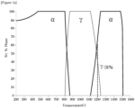
Figure 1a is a state diagram including γWt (1200 °C) of Example 3 using JMatPro. -
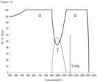
Figure 1b is a state diagram including γWt (1200 °C) of Example 10 using JMatPro. -
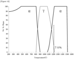
Figure 1c is a state diagram including γWt (1200 °C) of Comparative Example 1 using JMatPro. -
Figure 1d is a state diagram including γWt (1200 °C) of Comparative Example 6 using JMatPro. -
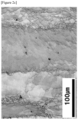
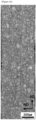
Figure 2a is a hot-rolled microstructure of Example 3 investigated by IQ (Image Quality) map. -
Figure 2b is a hot-rolled microstructure of Example 10 investigated by IQ (Image Quality) map. -
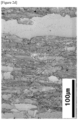
Figure 2c is a hot-rolled microstructure of Comparative Example 1 examined by IQ (Image Quality) map. -
Figure 2d is a hot-rolled microstructure of Comparative Example 6 investigated by IQ (Image Quality) map. -
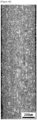
Figure 3a is a hot-rolled microstructure of Example 3 investigated by IPF (Inverse Pole Figure) map. -
Figure 3b is a hot-rolled microstructure of Example 10 investigated by IPF (Inverse Pole Figure) map. -
Figure 3c is a hot-rolled microstructure of Comparative Example 1 investigated by IPF (Inverse Pole Figure) map. -
Figure 3d is a hot-rolled microstructure of Comparative Example 6 investigated by IPF (Inverse Pole Figure) map. -
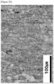
Figure 4a is a photograph showing the surface microstructure after cold rolling annealing of Example 3. -
Figure 4b is a photograph showing the surface microstructure after cold rolling annealing of Example 10. -
Figure 4c is a photograph showing the surface microstructure after cold rolling annealing of Comparative Example 1. -
Figure 4d is a photograph showing the surface microstructure after cold rolling annealing of Comparative Example 6. - A ferritic steel with improved ridging resistance according to an embodiment of the present invention comprises, by weight (wt%), 0.001 to 0.3% of C, 0.01 to 1.0% of Si, 0.1 to 3.0% of Mn, 10 to 15% of Cr, 0.001 to 0.3% of N, 0.03% or less of P, 1.0% or less of Ni, 1.0% or less of Cu, 1.0% or less of Al, 0.003% or less of Mo, 1.0% or less of Ti, the remainder of Fe, and other unavoidable impurities, wherein γ s represented by the following formula (1) is 6 or more.

- Preferred embodiments of the present invention are described below. However, the embodiments of the present invention can be modified in many different forms, and the technical concepts of the present invention is not limited to the embodiments described below. In addition, the embodiments of the present invention are provided to more completely explain the present invention to those skilled in the art.
- Terms used in this application are only used to describe specific examples. Therefore, for example, expressions in the singular number include plural expressions unless the context clearly requires them to be singular. In addition, the terms "include" or "have" used in this application are used to clearly indicate that the features, steps, functions, components, or combinations thereof described in the specification exist, but other features It should be noted that it is not intended to be used to preliminarily exclude the presence of any steps, functions, components, or combinations thereof.
- Meanwhile, unless otherwise defined, all terms used in this specification should be regarded as having the same representing as commonly understood by a person of ordinary skill in the art to which the present invention belongs. Accordingly, certain terms should not be interpreted in an overly idealistic or formal sense unless clearly defined herein. For example, in this specification, a singular expression includes a plurality of expressions unless there is a clear exception from the context.
- In addition, "about", "substantially", etc. in this specification are used at or in the sense of or close to the value when manufacturing and material tolerances inherent in the stated representing are presented and are accurate to aid in understanding the present invention. Or absolute numbers are used to prevent unfair use by unscrupulous infringers of the stated disclosure.
- A ferritic stainless steel with improved ridging resistance according to the present invention comprises, by weight (wt%), 0.001 to 0.3% of C, 0.01 to 1.0% of Si, 0.1 to 3.0% of Mn, 10 to 15% of Cr, 0.001 to 0.3% of N, 0.03% or less of P, 1.0% or less of Ni, 1.0% or less of Cu, 1.0% or less of Al, 0.003% or less of Mo, 1.0% or less of Ti, the remainder of Fe, and other unavoidable impurities,
- Hereinafter, the reason for limiting the composition range of each alloy element will be described below.
- The content of carbon (C) is 0.001 to 0.3%.
- C is an interstitial solid solution-strengthening element that improves the strength of the ferritic stainless steel. When the content of C is less than 0.001%, sufficient strength cannot be obtained by reducing the amount of carbide produced. However, if the content of C is excessive, the ductility, toughness, and corrosion resistance of the steel are reduced, so the upper limit is limited to 0.3%.
- The content of silicon (Si) is 0.01 to 1.0%.
- Si is an alloying element that is essentially added for deoxidation of molten steel during steelmaking, improves strength and corrosion resistance, and can be added in an amount of 0.01% or more in the present invention as an element that stabilizes the ferrite phase. However, when the content is excessive, there is a problem in that ductility and formability is lowered, so the upper limit is limited to 1.0%.
- The content of manganese (Mn) is 0.1 to 3.0%.
- Mn is an austenite phase stabilizing element and can induce austenite nucleation during hot rolling to promote crystal grain refinement. However, when the content is excessive, corrosion resistance is lowered, manganese-based fumes are generated during welding, and elongation is reduced by causing MnS phase precipitation. Therefore, in the present invention, the content of Mn is to be controlled to 0.1 to 3.0%.
- The content of chromium (Cr) is 10 to 15%.
- Cr is added in an amount of 10% or more as an element that improves corrosion resistance by forming a passivation film in chemical environment. However, when the content of Cr is excessive, there is a problem in that a sticking defect occurs due to the formation of a dense oxide scale during hot rolling, and the manufacturing cost increases. Therefore, in the present invention, the upper limit of the Cr content is intended to be limited to 15%.
- The content of nitrogen (N) is 0.001 to 0.3%.
- N, like carbon, is an interstitial solid-solution strengthening element that not only improves the strength of the ferritic stainless steel but also promotes recrystallization by precipitating an austenite phase during hot rolling. However, when the content is excessive, there is a problem with lowering the ductility of the steel. Therefore, in the present invention, the N content is controlled to 0.001 to 0.3%.
- The content of phosphorus (P) is 0.03% or less.
- P is an impurity inevitably contained in steel, and since it is an element that causes intergranular corrosion during pickling or inhibits hot workability, it is preferable to control the content thereof as low as possible. Therefore, in the present invention, the content of P is controlled to 0.03% or less.
- The content of nickel (Ni) is 1.0% or less.
- While Ni has the effect of improving corrosion resistance, when a large amount is added, there is a problem in that elongation decreases due to an increase in impurities in the material. In addition, Ni is a typical austenite stabilizing element or an expensive element, which increases manufacturing costs. Therefore, in the present invention, the content of Ni is controlled to 1.0% or less.
- The content of copper (Cu) is 1.0% or less.
- Cu is an element effective in improving corrosion resistance, workability, and ridging properties. However, when a large amount is added, there is a problem in that workability is lowered. Therefore, in the present invention, the content of Cu is controlled to 1.0% or less.
- The content of aluminum (Al) is 1.0% or less.
- Al is a ferrite-phase stabilizing element and serves as a strong deoxidizer to lower the oxygen content in molten steel. However, when the content is excessive, room temperature ductility is lowered, and sliver defects of the cold-rolled strip occur due to an increase in non-metallic inclusions, and at the same time, there is a problem of deteriorating weldability. Therefore, in the present invention, Al content is controlled to 1.0% or less.
- The content of molybdenum (Mo) is 0.003% or less.
- Mo is an element effective in improving the corrosion resistance of stainless steel. However, Mo is an expensive element that causes an increase in raw material costs and deteriorates workability when added in large amounts. Therefore, in the present invention, the content of Mo is controlled to 0.003% or less.
- The content of titanium (Ti) is 1.0% or less.
- Ti is an element effective in reducing the amount of solid solution C and solid solution N in steel and securing the corrosion resistance of steel by preferentially combining with interstitial elements such as carbon (C) and nitrogen (N) to form precipitates (carbonitrides). However, when the content is excessive, austenite stability is lowered, making it difficult to obtain fine grains, lowering toughness, and increasing titanium-based inclusions, resulting in surface defects. Therefore, in the present invention, the content of titanium is controlled to 1.0% or less.
- The remainder of the component of the present invention is iron (Fe). However, since unintended impurities from raw materials or the surrounding environment may inevitably be mixed in the normal manufacturing process, this cannot be excluded. Since these impurities are known to anyone skilled in the ordinary manufacturing process, not all of them are specifically mentioned in this specification.
- In addition, the ferritic stainless steel according to an embodiment of the present invention has γ s represented by the following formula (1) of 6 or more.

- (Austenite (gamma-phase) stability) is an index of austenite phase stability corresponding to the maximum amount of austenite at high temperatures. In the present invention, to induce austenite phase transformation during hot rolling by securing austenite phase stability, γ s value was intended to be limited to 6 or more. In addition, when γ s value is less than 6, the hot-rolled band structure of the ferritic stainless steel is not removed and remains, causing serious ridging defects.
- Induced austenite phase transformation in hot rolling by optimizing alloy components of the ferritic stainless steel. Accordingly, the ferritic stainless steel according to an embodiment of the present invention can secure fine crystal grains of single-phase ferrite without a band structure or colony structure. The size of the ferrite single-phase crystal grains may be 15 µm or less.
- Next, a method for manufacturing a ferritic stainless steel with improved ridging resistance according to another embodiment of the present invention will be described.
- According to an embodiment of the present invention, the manufacturing method of a ferritic stainless steel with improved ridging resistance comprising:
- reheating a slab at a temperature of 1050 to 1250°C, the slab comprising, in percent by weight (wt%), 0.001 to 0.3% of C, 0.01 to 1.0% of Si, 0.1 to 3.0% of Mn, 10 to 15% of Cr, 0.001 to 0.3% of N, 0.03% or less of P, 1.0% or less of Ni, 1.0% or less of Cu, 1.0% or less of Al, 0.003% or less of Mo, 1.0% or less of Ti, the remainder of Fe, and other unavoidable impurities, wherein γs represented by the following formula (1) is 6 or more;
- hot rolling the reheated slab; and
- cold rolling and cold rolling annealing the hot rolled material;
- wherein, in the reheating step, γWt (T) , defined as austenite weight% at the temperature T, is controlled to satisfy the following formula (2).


- The reason for limiting the composition range of each alloy element is as described above.
- γWt (T) (Austenite (gamma-phase) Weight at temperature T) is the weight percent austenite at temperature T, in the reheating phase. Even if γS satisfies 6 or more, the stability of austenite phase decreases when the reheating temperature is high. When the stability of austenite phase is lowered, austenite phase transformation does not sufficiently occur during hot rolling, and the hot-rolled band structure remains on the surface of the ferritic stainless steel.
- As a result of examining various control conditions using JmatPro, it was possible to secure fine ferrite crystal grains on the surface of the ferritic stainless steel after hot rolling when austenite weight% was controlled to 19% or more at a reheating temperature of 1200°C.
- In addition, according to an embodiment of the present invention, in the reheating step, the following equation (3) may be satisfied.

- When the value of Equation (3) representing the product of Equations (1) and (2) is 114 or more while satisfying Equations (1) and (2), the ridging height can be suppressed to 10 µm or less as desired in the present invention.
- Next, to secure a desired final thickness during hot rolling, finish rolling (finish rolling) may be performed at 700 to 950 °C.
- If the temperature of finish rolling is maintained below 700°C, sticking defects occur on the plate surface of the slab during hot rolling. In addition, to roll the slabs to an appropriate thickness, hot rolling should be performed at 700°C or higher.
- On the other hand, when the temperature of finish rolling exceeds 900°C, relatively large ferrite crystal grains are formed. Therefore, in the present invention, the temperature of finish rolling is controlled to 900°C or less so that fine ferrite crystal grains can be made after hot rolling.
- Hot-rolled products undergo surface pickling treatment for cold rolling. At this time, hot rolling annealing may be omitted. However, when excessively fine ferrite crystal grains are formed or there is a decrease in elongation due to residual dislocation, the hot-rolled material may be hot-rolled and annealed.
- Accordingly, according to one embodiment of the present invention, after the hot rolling, a step of hot rolling annealing may be further included. Hot rolling annealing is preferably carried out at 600 to 900°C to remove the stress formed during hot rolling without regenerating austenite phase.
- In this way, by optimizing the reheating and hot rolling processes as well as alloy components and component relations, it is possible to secure the surface characteristics of the ferritic stainless steel by deriving the fine crystal grains of the ferrite single phase.
- Hereinafter, the present invention will be described in more detail through examples. However, it should be noted that the following examples are only for illustrating the present invention in more detail, and are not intended to limit the scope of the present invention. This is because the scope of the present invention is determined by the matters described in the claims and the matters reasonably inferred therefrom.
- For the various alloy composition ranges shown in Table 1 below, slabs were prepared by continuous casting and reheated at 1,050 to 1,200°C. Next, the reheated slab was finish-rolled at a temperature of 700 to 950°C.
[Table 1] Classi ficati on Alloy element (wt%) C Si Mn P Cr Ni Cu Mo Al Ti Nb N Exam ple 1 0.0 11 0.2 4 0.4 8 0.0 24 11. 2 0.7 8 0 0 0.0 2 0.1 8 0 0.0 1 Exam ple 2 0.0 07 0.2 3 0.5 0.0 23 11 0.7 9 0.1 9 0 0.0 17 0.1 7 0 0.0 1 Exam ple 3 0.0 07 0.1 5 0.9 0.0 2 10. 6 0 0.3 0 0 0.1 5 0 0.0 08 Exam ple 4 0.0 11 0.2 1 0.0 2 10. 8 0 0.3 1 0 0 0.2 2 0 0.0 1 Exam ple 5 0.0 11 0.1 5 1 0.0 2 10. 6 0 0.3 1 0 0 0.1 5 0 0.0 1 Exam ple 6 0.0 07 0.1 0.9 0.0 2 10. 5 0 0.3 0 0 0.1 35 0 0.0 08 Exam ple 7 0.0 11 0.1 1 0.0 2 10. 5 0 0.3 1 0 0 0.1 35 0 0.0 1 Exam ple 8 0.0 05 0.1 0.8 2 0.0 2 10. 5 0 0.2 1 0 0 0.1 35 0 0.0 04 Exam ple 9 0.0 05 0.1 5 0.8 2 0.0 2 10. 6 0 0.2 1 0 0 0.1 5 0 0.0 04 Exam ple 1 0 0.0 07 0.2 0.9 0.0 2 14. 1 0 0.4 0 0 0 0 0.0 57 Comp arativ e Exam ple 1 0.0 06 0.5 5 0.3 0.0 22 11. 2 0 0 0 0 0.2 0 0.0 08 Comp arativ e Exam ple 2 0.0 06 0.5 2 0.1 5 0.0 24 11. 1 0.8 0 0 0.0 26 0.1 9 0 0.0 072 Comp arativ e Exam ple 3 0.0 05 0.2 0.8 2 0.0 2 10. 8 0 0.2 1 0 0 0.2 2 0 0.0 04 Comp arativ e Exam ple 4 0.0 07 0.2 0.9 0.0 2 10. 8 0 0.3 0 0 0.2 2 0 0.0 08 Comp arativ e Exam ple 5 0.0 07 0.8 5 0.3 0.0 2 15 0 0 0 0 0.1 3 0.4 0.0 06 Comp arativ e Exam ple 6 0.0 07 0.2 4.6 0.0 2 14. 1 0 2 0 0 0.2 0 0.0 08 Comp arativ e Exam ple 7 0.0 07 0.1 2 0.0 2 14. 1 0 2.5 - 0 0.2 0 0 0.0 08 - The hot-rolled material is pickled and cold-rolled to a thickness of 70 or less so that austenite phase is not regenerated. It was cold annealed at 900°C. After that, the cold burnt dull material was stretched by 15% in the rolling direction, and the height of the ridging curve was measured with a surface roughness instrument. Table 2 below shows values of γS, γWt (1200°C), γS ∗ γWt (1200°C), and ridging height (µm) of the Examples and Comparative Examples.
[Table 2] Classification Ys γWt (1200°C) (%) Ys* γWt (1200°C) Ridging height (µm) Example 1 13.6 33 450.1 6.3 Example 2 17.1 43 736.8 4.4 Example 3 14.3 31 441.8 6.2 Example 4 12.7 22 280.3 8.6 Example 5 21.1 42 884.9 4.8 Example 6 18.2 39 709.2 5.2 Example 7 25.0 51 1275.3 4.1 Example 8 10.5 26 274.2 8.1 Example 9 6.6 19 125.6 9.3 Example 10 8.4 23 192.05 5.6 Comparative Example 1 -22.1 0 0.0 22.9 Comparative Example 2 -4.5 8 -36.2 20.5 Comparative Example 3 -1.7 2 -3.4 21.7 Comparative Example 4 5.9 11 65.1 17.6 Comparative Example 5 -93.3 0 0.0 23.5 Comparative Example 6 15.6 18 280.8 13.8 Comparative Example 7 -7.2 24 -172.8 12.4 - Referring to Table 2, Examples 1 to 10 satisfy γS of 6 or more, γWt (1200°C) of 19% or more, and γS ∗ γWt (1200°C) of 114 or more. Accordingly, in Examples 1 to 10, the ridging height was 10 µm or less, and the surface quality was good.
- On the other hand, in Comparative Example 1, γS is -22.1 and less than 6, γWt (1200°C) is 0% and less than 19%, and γS ∗ γWt (1200°C) is 0 and less than 114. Accordingly, in Comparative Example 1, a ridging defect having a height of 22.9 µm occurred.
- In Comparative Examples 2 to 5, γS is less than 6, γS ∗ γWt (1200°C) is less than 19%, and γS ∗ γWt (1200°C) is less than 114. Accordingly, all of the Comparative Examples 2 to 5 had ridging defects larger than 10 µm.
- In Comparative Example 6, γS is 15.6, which satisfies 6 or more suggested in the present invention, and γS ∗ γWt (1200°C) has a value of 280.8, which is 114 or more. However, in Comparative Example 6, γWt (1200°C) was 18% and less than 19%, resulting in ridging defects of 13.8 µm larger than 10 µm.
- In Comparative Example 7, γWt (1200°C) is 24%, which is 19% or more. However, in Comparative Example 7, is -7.2, less than 6, and γS ∗ γWt (1200°C) is -172.8, less than 114. Accordingly, in Comparative Example 7, a ridging defect of 12.4 µm, which is larger than 10 µm, occurred.
- Through the disclosed Examples and Comparative Examples, it was found that when the ranges of γS, γWt (1200°C) and γS ∗ γWt (1200°C) proposed by the present invention are satisfied, ridging defects of 10 µm or less occur.
- Table 3 below shows the measured values of the band structure observed after hot rolling and the band structure observed after cold rolling annealing and ferrite crystal grain sizes for Example 3, Example 10, Comparative Example 1, and Comparative Example 6.
[Table 3] Classification Observation of band organization after hot rolling Observation of band organization after cold annealing Ferrite grain size after cold annealing Note Example 3 X X 10.8 µm Figure 2a andFigure 3a Example 10 X X 11.2 µm Figure 2b andFigure 3b Comparative Example 1 O X 35.1 µm Figure 2c andFigure 3c Comparative Example 6 O X 18.9 µm Figure 2d andFigure 3d - Referring to Table 3 and
Figures 2a to 2d , in Examples 3 and 10, no band structure was observed, and fine ferrite grains were evenly distributed. On the other hand, in Comparative Example 1 and Comparative Example 6, a band structure remainder after hot rolling was observed. - Referring to Table 3 and
Figures 4a to 4d , the ferrite grain size of Example 3 is 10.8 µm, and the ferrite grain size of Example 10 is 11.2 µm. On the other hand, the ferrite grain size of Comparative Example 1 is 35.1 µm, and the ferrite grain size of Comparative Example 6 is 18.9 µm. - No band structure was observed on the surfaces of Examples 3 and 10 and Comparative Examples 1 and 6 after cold annealing. However, in the case of Comparative Example 1 and Comparative Example 6, it can be confirmed that the size of the ferrite grains was greater than 15 µm and coarser than that of the Examples.
- According to the disclosed embodiment, by optimizing not only alloy components and component relations, but also reheating and hot rolling conditions, band structures or colony structures are not expressed on the surface, and the ridging height is suppressed to 10 µm or less so that the ferritic stainless steel is uniform. Surface quality can be ensured.
- In the foregoing, exemplary embodiments of the present invention have been described, but the present invention is not limited thereto, and those skilled in the art within the scope that does not deviate from the concept and scope of the claims described below. It will be appreciated if many changes and modifications are possible.
Claims (7)
- A ferritic stainless steel with improved ridging resistance comprising, in percent by weight (wt%), 0.001 to 0.3% of C, 0.01 to 1.0% of Si, 0.1 to 3.0% of Mn, 10 to 15% of Cr, 0.001 to 0.3% of N, 0.03% or less of P, 1.0% or less of Ni, 1.0% or less of Cu, 1.0% or less of Al, 0.003% or less of Mo, 1.0% or less of Ti, the remainder of Fe, and other unavoidable impurities, wherein γ s represented by the following formula (1) is 6 or more.

- The ferritic stainless steel with improved ridging resistance according to claim 1, wherein a ferrite grain size is 15 µm or less.
- The ferritic stainless steel with improved ridging resistance according to claim 1, wherein a ridging height (Wt) is 10 µm or less, measured after 15% elongation at a thickness of 1.0mm or less.
- A manufacturing method of a ferritic stainless steel with improved ridging resistance comprising:reheating a slab at a temperature of 1050 to 1250°C, the slab comprising, in percent by weight (wt%), 0.001 to 0.3% of C, 0.01 to 1.0% of Si, 0.1 to 3.0% of Mn, 10 to 15% of Cr, 0.001 to 0.3% of N, 0.03% or less of P, 1.0% or less of Ni, 1.0% or less of Cu, 1.0% or less of Al, 0.003% or less of Mo, 1.0% or less of Ti, the remainder of Fe, and other unavoidable impurities, wherein γ s represented by the following formula (1) is 6 or more;hot rolling the reheated slab; andcold rolling and cold rolling annealing the hot rolled material;wherein, in the reheating step, γWt (T), defined as austenite weight% at the temperature T, is controlled to satisfy the following formula (2).
 (wherein, C, Si, Mn, Ni, Cr, Mo, Cu, Ti, Al, and N represent the content (wt%) of each element)
- The manufacturing method of a ferritic stainless steel with improved ridging resistance according to claim 4, wherein the reheating step satisfies the following formula (3).

- The manufacturing method of a ferritic stainless steel with improved ridging resistance according to claim 4, wherein the hot rolling step comprises finishing rolling at a temperature of 700 to 950°C.
- The manufacturing method of a ferritic stainless steel with improved ridging resistance according to claim 4, wherein after hot rolling step, hot rolling step further comprises hot rolling annealing at a temperature of 600 to 900°C.
Applications Claiming Priority (2)
| Application Number | Priority Date | Filing Date | Title |
|---|---|---|---|
| KR1020200171165A KR102497439B1 (en) | 2020-12-09 | 2020-12-09 | Ferritic stainless steel with improved ridging resistance and its manufacturing method |
| PCT/KR2021/011464 WO2022124526A1 (en) | 2020-12-09 | 2021-08-26 | Ferrite-based stainless steel having improved ridging resistance and method for manufacturing same |
Publications (2)
| Publication Number | Publication Date |
|---|---|
| EP4261319A1 true EP4261319A1 (en) | 2023-10-18 |
| EP4261319A4 EP4261319A4 (en) | 2025-10-15 |
Family
ID=81973664
Family Applications (1)
| Application Number | Title | Priority Date | Filing Date |
|---|---|---|---|
| EP21903573.0A Pending EP4261319A4 (en) | 2020-12-09 | 2021-08-26 | Ferrite-based stainless steel with improved grooving resistance and method for producing the same |
Country Status (5)
| Country | Link |
|---|---|
| US (1) | US20240035134A1 (en) |
| EP (1) | EP4261319A4 (en) |
| KR (1) | KR102497439B1 (en) |
| CN (1) | CN116635560B (en) |
| WO (1) | WO2022124526A1 (en) |
Family Cites Families (16)
| Publication number | Priority date | Publication date | Assignee | Title |
|---|---|---|---|---|
| JP3241114B2 (en) * | 1992-07-14 | 2001-12-25 | 日新製鋼株式会社 | Method for producing ferritic stainless steel sheet excellent in ridging property and workability |
| JP2772237B2 (en) * | 1994-03-29 | 1998-07-02 | 川崎製鉄株式会社 | Method for producing ferritic stainless steel strip with small in-plane anisotropy |
| JP3477098B2 (en) * | 1998-12-25 | 2003-12-10 | 新日本製鐵株式会社 | Ferritic stainless steel sheet excellent in surface properties and ridging properties and method for producing the same |
| JP4003821B2 (en) * | 1999-03-05 | 2007-11-07 | 日本冶金工業株式会社 | Method for producing ferritic stainless steel sheet with excellent ridging resistance |
| JP4221107B2 (en) * | 1999-03-19 | 2009-02-12 | 新日本製鐵株式会社 | Method for producing ferritic stainless steel sheet with excellent surface properties |
| KR100406406B1 (en) | 1999-08-24 | 2003-11-19 | 주식회사 포스코 | Process for producing hot rolled ferrite stainless steel having superior ridging resistance with preventing from sticking |
| KR100467719B1 (en) | 2000-12-08 | 2005-01-24 | 주식회사 포스코 | Method of producing ferritic stainless steel sheets having softning, anti-ridging property and excellent spinning formability |
| JP4082205B2 (en) * | 2002-12-20 | 2008-04-30 | Jfeスチール株式会社 | Ferritic stainless steel sheet excellent in workability and ridging resistance and method for producing the same |
| KR101317275B1 (en) * | 2011-11-03 | 2013-10-14 | 포항공과대학교 산학협력단 | Steel sheet having good low temperature toughness |
| KR101522077B1 (en) * | 2012-12-20 | 2015-05-20 | 주식회사 포스코 | Manufacturing method of ferritic stainless steel sheet with excellent ridging resistance |
| CN106232838A (en) | 2013-12-24 | 2016-12-14 | Posco公司 | Ferritic stainless steel with improved formability and wrinkle resistance and manufacturing method thereof |
| CN105331899A (en) * | 2015-09-24 | 2016-02-17 | 宝钢不锈钢有限公司 | Ferritic stainless steel with good crease resistance and manufacturing method of ferritic stainless steel |
| JP6489254B2 (en) * | 2017-04-25 | 2019-03-27 | Jfeスチール株式会社 | Material for stainless cold-rolled steel sheet and manufacturing method thereof |
| JP6432701B2 (en) * | 2017-04-25 | 2018-12-05 | Jfeスチール株式会社 | Ferritic stainless steel sheet and manufacturing method thereof |
| JP6680279B2 (en) * | 2017-08-31 | 2020-04-15 | Jfeスチール株式会社 | Ferritic stainless steel sheet and method of manufacturing the same |
| KR102173277B1 (en) * | 2018-11-06 | 2020-11-03 | 주식회사 포스코 | Hot-rolled steel sheet with excellent low temperature impact toughness and manufacturing method thereof |
-
2020
- 2020-12-09 KR KR1020200171165A patent/KR102497439B1/en active Active
-
2021
- 2021-08-26 EP EP21903573.0A patent/EP4261319A4/en active Pending
- 2021-08-26 US US18/265,345 patent/US20240035134A1/en active Pending
- 2021-08-26 WO PCT/KR2021/011464 patent/WO2022124526A1/en not_active Ceased
- 2021-08-26 CN CN202180082869.3A patent/CN116635560B/en active Active
Also Published As
| Publication number | Publication date |
|---|---|
| US20240035134A1 (en) | 2024-02-01 |
| KR102497439B1 (en) | 2023-02-08 |
| CN116635560B (en) | 2026-04-07 |
| CN116635560A (en) | 2023-08-22 |
| KR20220081556A (en) | 2022-06-16 |
| EP4261319A4 (en) | 2025-10-15 |
| WO2022124526A1 (en) | 2022-06-16 |
Similar Documents
| Publication | Publication Date | Title |
|---|---|---|
| US5624504A (en) | Duplex structure stainless steel having high strength and elongation and a process for producing the steel | |
| EP3231882B1 (en) | Stainless steel and production method therefor | |
| JP6037084B2 (en) | Steel plate for squeezed can and method for manufacturing the same | |
| JP5219689B2 (en) | Ferritic stainless steel sheet with low surface roughness and manufacturing method thereof | |
| TW202233864A (en) | Martensite-based stainless steel material and method for producing same | |
| WO2024225118A1 (en) | Martensitic stainless-steel material, method for producing same, and method for producing cutting article | |
| EP3498877B1 (en) | High strength steel sheet having excellent formability and manufacturing method thereof | |
| JP4682806B2 (en) | Ferritic stainless steel cold-rolled steel sheet excellent in press formability and manufacturing method thereof | |
| JPWO2000006791A1 (en) | Ferritic thin steel sheet with excellent shape fixability and its manufacturing method | |
| JP2001089815A (en) | Method for producing ferritic stainless steel sheet with excellent ductility, workability and ridging resistance | |
| JP3288626B2 (en) | High workability ferritic stainless steel sheet excellent in ridging characteristics and method for producing the same | |
| JP4166657B2 (en) | Ferritic stainless steel sheet and manufacturing method thereof | |
| KR102523533B1 (en) | Ferritic stainless steel with improved grain boundary erosion and its manufacturing method | |
| KR102497439B1 (en) | Ferritic stainless steel with improved ridging resistance and its manufacturing method | |
| KR101421832B1 (en) | Ferritic stainless steel sheet with excellent ridging resistance and manufacturing method thereof | |
| KR100435457B1 (en) | A method for manufacturing ferritic stainless steel having improvable formability and ridging resistance | |
| JP2001207244A (en) | Ferritic stainless cold-rolled steel sheet excellent in ductility, workability and ridging resistance and method for producing the same | |
| KR20200032899A (en) | Manufacturing method of ferritic stainless steel having excellent ridging property and formability | |
| KR0146798B1 (en) | Ferritic stainless steel manufacturing method with excellent formability and stiffness resistance | |
| KR20230093653A (en) | High-strength ferrite stainless steel having excellent formability, and method for manufacturing thereof | |
| JPH10130734A (en) | Manufacturing method of austenitic stainless steel sheet for roll forming | |
| JP2001089814A (en) | Method for producing ferritic stainless steel sheet with excellent ductility, workability and ridging resistance | |
| EP4397781A1 (en) | Hot-rolled ferritic stainless steel sheet having excellent formability and method for manufacturing same | |
| JP3923485B2 (en) | Manufacturing method of ferritic single-phase stainless steel with excellent deep drawability | |
| JPH1112691A (en) | Ferritic stainless steel cold-rolled steel sheet excellent in formability and method for producing the same |
Legal Events
| Date | Code | Title | Description |
|---|---|---|---|
| STAA | Information on the status of an ep patent application or granted ep patent |
Free format text: STATUS: THE INTERNATIONAL PUBLICATION HAS BEEN MADE |
|
| PUAI | Public reference made under article 153(3) epc to a published international application that has entered the european phase |
Free format text: ORIGINAL CODE: 0009012 |
|
| STAA | Information on the status of an ep patent application or granted ep patent |
Free format text: STATUS: REQUEST FOR EXAMINATION WAS MADE |
|
| 17P | Request for examination filed |
Effective date: 20230606 |
|
| AK | Designated contracting states |
Kind code of ref document: A1 Designated state(s): AL AT BE BG CH CY CZ DE DK EE ES FI FR GB GR HR HU IE IS IT LI LT LU LV MC MK MT NL NO PL PT RO RS SE SI SK SM TR |
|
| DAV | Request for validation of the european patent (deleted) | ||
| DAX | Request for extension of the european patent (deleted) | ||
| REG | Reference to a national code |
Ref country code: DE Ref legal event code: R079 Free format text: PREVIOUS MAIN CLASS: C22C0038580000 Ipc: C22C0038180000 |
|
| A4 | Supplementary search report drawn up and despatched |
Effective date: 20250912 |
|
| RIC1 | Information provided on ipc code assigned before grant |
Ipc: C22C 38/18 20060101AFI20250908BHEP Ipc: C22C 38/04 20060101ALI20250908BHEP Ipc: C22C 38/02 20060101ALI20250908BHEP Ipc: C22C 38/00 20060101ALI20250908BHEP Ipc: C22C 38/20 20060101ALI20250908BHEP Ipc: C22C 38/28 20060101ALI20250908BHEP Ipc: C22C 38/40 20060101ALI20250908BHEP Ipc: C22C 38/42 20060101ALI20250908BHEP Ipc: C22C 38/50 20060101ALI20250908BHEP Ipc: C22C 38/06 20060101ALI20250908BHEP Ipc: C22C 38/58 20060101ALI20250908BHEP Ipc: C21D 9/46 20060101ALI20250908BHEP Ipc: C21D 9/48 20060101ALI20250908BHEP Ipc: C21D 8/02 20060101ALI20250908BHEP Ipc: C21D 8/04 20060101ALI20250908BHEP Ipc: C21D 6/00 20060101ALI20250908BHEP Ipc: C21D 1/26 20060101ALI20250908BHEP |