EP4261069A1 - Anzeigevorrichtung und drehanordnung - Google Patents
Anzeigevorrichtung und drehanordnung Download PDFInfo
- Publication number
- EP4261069A1 EP4261069A1 EP22196461.2A EP22196461A EP4261069A1 EP 4261069 A1 EP4261069 A1 EP 4261069A1 EP 22196461 A EP22196461 A EP 22196461A EP 4261069 A1 EP4261069 A1 EP 4261069A1
- Authority
- EP
- European Patent Office
- Prior art keywords
- clamping structure
- tenon
- hole
- clamping
- structures
- Prior art date
- Legal status (The legal status is an assumption and is not a legal conclusion. Google has not performed a legal analysis and makes no representation as to the accuracy of the status listed.)
- Pending
Links
Images
Classifications
-
- G—PHYSICS
- G06—COMPUTING OR CALCULATING; COUNTING
- G06F—ELECTRIC DIGITAL DATA PROCESSING
- G06F1/00—Details not covered by groups G06F3/00 - G06F13/00 and G06F21/00
- G06F1/16—Constructional details or arrangements
- G06F1/1601—Constructional details related to the housing of computer displays, e.g. of CRT monitors, of flat displays
-
- B—PERFORMING OPERATIONS; TRANSPORTING
- B60—VEHICLES IN GENERAL
- B60K—ARRANGEMENT OR MOUNTING OF PROPULSION UNITS OR OF TRANSMISSIONS IN VEHICLES; ARRANGEMENT OR MOUNTING OF PLURAL DIVERSE PRIME-MOVERS IN VEHICLES; AUXILIARY DRIVES FOR VEHICLES; INSTRUMENTATION OR DASHBOARDS FOR VEHICLES; ARRANGEMENTS IN CONNECTION WITH COOLING, AIR INTAKE, GAS EXHAUST OR FUEL SUPPLY OF PROPULSION UNITS IN VEHICLES
- B60K35/00—Instruments specially adapted for vehicles; Arrangement of instruments in or on vehicles
- B60K35/20—Output arrangements, i.e. from vehicle to user, associated with vehicle functions or specially adapted therefor
- B60K35/21—Output arrangements, i.e. from vehicle to user, associated with vehicle functions or specially adapted therefor using visual output, e.g. blinking lights or matrix displays
- B60K35/22—Display screens
-
- B—PERFORMING OPERATIONS; TRANSPORTING
- B60—VEHICLES IN GENERAL
- B60K—ARRANGEMENT OR MOUNTING OF PROPULSION UNITS OR OF TRANSMISSIONS IN VEHICLES; ARRANGEMENT OR MOUNTING OF PLURAL DIVERSE PRIME-MOVERS IN VEHICLES; AUXILIARY DRIVES FOR VEHICLES; INSTRUMENTATION OR DASHBOARDS FOR VEHICLES; ARRANGEMENTS IN CONNECTION WITH COOLING, AIR INTAKE, GAS EXHAUST OR FUEL SUPPLY OF PROPULSION UNITS IN VEHICLES
- B60K2360/00—Indexing scheme associated with groups B60K35/00 or B60K37/00 relating to details of instruments or dashboards
- B60K2360/816—Fastening of displays or touch screens
-
- B—PERFORMING OPERATIONS; TRANSPORTING
- B60—VEHICLES IN GENERAL
- B60K—ARRANGEMENT OR MOUNTING OF PROPULSION UNITS OR OF TRANSMISSIONS IN VEHICLES; ARRANGEMENT OR MOUNTING OF PLURAL DIVERSE PRIME-MOVERS IN VEHICLES; AUXILIARY DRIVES FOR VEHICLES; INSTRUMENTATION OR DASHBOARDS FOR VEHICLES; ARRANGEMENTS IN CONNECTION WITH COOLING, AIR INTAKE, GAS EXHAUST OR FUEL SUPPLY OF PROPULSION UNITS IN VEHICLES
- B60K2360/00—Indexing scheme associated with groups B60K35/00 or B60K37/00 relating to details of instruments or dashboards
- B60K2360/828—Mounting or fastening exchangeable modules
- B60K2360/834—Docking arrangements
-
- B—PERFORMING OPERATIONS; TRANSPORTING
- B60—VEHICLES IN GENERAL
- B60K—ARRANGEMENT OR MOUNTING OF PROPULSION UNITS OR OF TRANSMISSIONS IN VEHICLES; ARRANGEMENT OR MOUNTING OF PLURAL DIVERSE PRIME-MOVERS IN VEHICLES; AUXILIARY DRIVES FOR VEHICLES; INSTRUMENTATION OR DASHBOARDS FOR VEHICLES; ARRANGEMENTS IN CONNECTION WITH COOLING, AIR INTAKE, GAS EXHAUST OR FUEL SUPPLY OF PROPULSION UNITS IN VEHICLES
- B60K2360/00—Indexing scheme associated with groups B60K35/00 or B60K37/00 relating to details of instruments or dashboards
- B60K2360/84—Mounting of dashboard components
-
- B—PERFORMING OPERATIONS; TRANSPORTING
- B60—VEHICLES IN GENERAL
- B60K—ARRANGEMENT OR MOUNTING OF PROPULSION UNITS OR OF TRANSMISSIONS IN VEHICLES; ARRANGEMENT OR MOUNTING OF PLURAL DIVERSE PRIME-MOVERS IN VEHICLES; AUXILIARY DRIVES FOR VEHICLES; INSTRUMENTATION OR DASHBOARDS FOR VEHICLES; ARRANGEMENTS IN CONNECTION WITH COOLING, AIR INTAKE, GAS EXHAUST OR FUEL SUPPLY OF PROPULSION UNITS IN VEHICLES
- B60K35/00—Instruments specially adapted for vehicles; Arrangement of instruments in or on vehicles
- B60K35/50—Instruments characterised by their means of attachment to or integration in the vehicle
- B60K35/53—Movable instruments, e.g. slidable
-
- B—PERFORMING OPERATIONS; TRANSPORTING
- B60—VEHICLES IN GENERAL
- B60R—VEHICLES, VEHICLE FITTINGS, OR VEHICLE PARTS, NOT OTHERWISE PROVIDED FOR
- B60R11/00—Arrangements for holding or mounting articles, not otherwise provided for
- B60R2011/0042—Arrangements for holding or mounting articles, not otherwise provided for characterised by mounting means
- B60R2011/008—Adjustable or movable supports
- B60R2011/0085—Adjustable or movable supports with adjustment by rotation in their operational position
-
- G—PHYSICS
- G06—COMPUTING OR CALCULATING; COUNTING
- G06F—ELECTRIC DIGITAL DATA PROCESSING
- G06F2200/00—Indexing scheme relating to G06F1/04 - G06F1/32
- G06F2200/16—Indexing scheme relating to G06F1/16 - G06F1/18
- G06F2200/161—Indexing scheme relating to constructional details of the monitor
- G06F2200/1612—Flat panel monitor
-
- G—PHYSICS
- G06—COMPUTING OR CALCULATING; COUNTING
- G06F—ELECTRIC DIGITAL DATA PROCESSING
- G06F2200/00—Indexing scheme relating to G06F1/04 - G06F1/32
- G06F2200/16—Indexing scheme relating to G06F1/16 - G06F1/18
- G06F2200/161—Indexing scheme relating to constructional details of the monitor
- G06F2200/1614—Image rotation following screen orientation, e.g. switching from landscape to portrait mode
Definitions
- the subject matter herein relates to technical field of automobile control, especially relates to a displaying device and a rotating assembly.
- the fixed horizontal screen or vertical screen cannot meet the user's need to rotate the screen arbitrarily.
- a user needs the vehicle central control screen to be able to switch between the horizontal screen and vertical screen.
- the present disclosure provides a displaying device and a rotating assembly, to solve the problem of switching the horizontal screen or vertical screen flexibly.
- the displaying device includes a displaying assembly and a transmitting assembly connected to the displaying assembly.
- the displaying assembly includes a displaying panel and a first clamping structure connected to the displaying panel.
- the first clamping structure includes tenon structures and fixing structures, the tenon structures are positioned between the fixing structures.
- the transmitting assembly includes a second clamping structure and a connecting structure, the second clamping structure is coupled to the first clamping structure, the clamping structure comprises a clamping joint, the clamping joint is coupled to the tenon structure, fixing grooves are defined on the second clamping structure, number and profile of the fixing grooves are matched with the fixing structures, and an end of the connecting structure is fixedly connected to the second clamping structure.
- the rotating assembly includes a first clamping structure for connecting a displaying panel, a transmitting assembly, and a driving assembly.
- the first clamping structure includes tenon structures and fixing structures, the tenon structures are positioned between the fixing structures.
- the transmitting assembly includes a second clamping structure and a connecting structure, the second clamping structure is coupled to the first clamping structure, the clamping structure comprises a clamping joint, the clamping joint is coupled to the tenon structure, and fixing grooves are defined on the second clamping structure. Number and profile of the fixing grooves are matched with the fixing structures, an end of the connecting structure is fixedly connected to the second clamping structure.
- the driving assembly includes a driving member, an output shaft of the driving member is connected to the connecting structure.
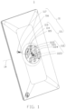
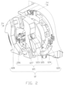
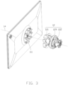
- a displaying device 1 as shown can rotate around a rotating axis 14 automatically, and the displaying device 1 includes a displaying assembly 11 and a transmission assembly 12.
- FIG. 1 is a schematic view of the displaying assembly 11 of a displaying device 1.
- FIG. 2 is a schematic view of the transmission assembly 12 of the display device 1. The displaying assembly 11 is coupled to the transmission assembly 12.
- the displaying assembly 11 includes a displaying panel and a first clamping structure 111 connected to the displaying panel.
- the first clamping structure 111 includes tenon structures 112 and fixing structures 113. An extending direction of the tenon structures 112 and the fixing structures 113 is parallel to the rotating axis 14.
- the tenon structures 112 are positioned between the fixing structures 113.
- the transmission assembly 12 includes a second clamping structure 121 and a connecting structure 122.
- the second clamping structure 121 is detachably coupled to the first clamping structure 111.
- the second clamping structure 121 includes clamping joints 123.
- the clamping joints 123 and the tenon structures 112 are staggered, and the clamping joints 123 can be inserted in gaps between the tenon structures 112 when the clamping joints 123 and the tenon structures 112 are coupled.
- Fixing grooves 124 corresponding to the fixing structures 113 are defined on the second clamping structure 121.
- the fixing grooves 124 are matched with the fixing structures 113.
- An end of the connecting structure 122 is fixedly connected to the second clamping structure 121.
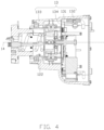
- a first connecting hole 114 is defined on the first clamping structure 111.
- a second connecting hole 125 is defined on the second clamping structure 121.
- the first connecting hole 114 is detachable and communicates with the second connecting hole 125.
- a connecting member 117 is positioned in the first connecting hole 114 and the second connecting hole 125.
- the first clamping structure 111 is fixed to the second clamping structure 121 through the connecting member 117.
- the clamping joints 123 are coupled to the tenon structures 112, and the fixing structures 113 are positioned in the fixing grooves 124.
- the first connecting hole 114 can communicate with the second connecting hole 125.
- the connecting member 117 is inserted in the first connecting hole 114 and the second connecting hole 125, the first clamping structure 111 is fixed to the second clamping structure 121.
- the first connecting hole 114 is defined at a side of the fixing structure 113.
- the second connecting hole 125 is defined at a side of the clamping joint 123.
- the connecting member 117 may be a screw or a pin.
- the second connecting hole 125 may be a screw hole or a cylindrical hole.
- the connecting structure 122 is fixedly connected to the second clamping structure 121.
- the connecting portion 122 can transmit the rotational torque to the clamping joint 123. Due to the fixed connection between the second clamping structure 121 and the first clamping structure 111, the clamping joints 123 transmit the rotational torque to the tenon structures 112 and the fixing structures 113, and the displaying assembly 11 can be freely rotated to horizontal or vertical orientations.
- the displaying panel may be one of central control screen, displaying screen, and navigator.
- the first clamping structure 111 is positioned at a back plate of the central control screen.
- the tenon structures 112 and the fixing structures 113 of the first clamping structure 111 are spaced apart and positioned at a center of the central control screen.
- the transmitting assembly 12 may be one of a rotating body such as a cylinder, a disk, and a connecting shaft. A central axis of the transmitting assembly 12 is coaxial with the rotating axis 14.
- a receiving hole 115 is defined on the first clamping structure 115, and receiving hole 115 is located between the tenon structures 112.
- the displaying assembly 11 further comprises a first signal interface 116.
- the first signal interface 116 is positioned in the receiving hole 115.
- the first signal interface 116 is configured to provide signals to the central control screen.
- the tenon structures 112 includes a first tenon 1121, a second tenon 1122, and a third tenon 1123, which are arranged around the receiving hole 15.
- the first tenon 1121 includes a symmetrical bending part 1124.
- the second tenon 1122 and the third tenon 1123 are arranged symmetrically around the receiving hole 115.
- the first signal interface 116 is coaxial with the rotating axis 14, so that the first signal interface 116 rotates coaxially with the rotating axis 14.
- the clamping joints 123 are inserted in gaps between the first tenon 1121, the second tenon 1122, and the third tenon 1123, thus connecting strength between the first clamping structure 111 and the second clamping structure 121 can be improved.
- the first tenon 1121, the second tenon 1122, and the third tenon 1123 balance the distribution of the rotating torque, thereby enabling smooth rotation of the first signal interface 116.
- the receiving hole 115 is arranged at the center position of the back plate of the central control screen.
- the receiving hole 115 may be a blind hole, and the signal interface 116 is installed in the receiving hole 115.
- An axis of the receiving hole 115 is coaxial with the rotating axis 14.
- the receiving hole 115 is arranged between the tenon structures 112, and the tenon structures 112 function to fix the position and angle of the first signal interface 116, so that connection of the first signal interface 116 is not affected by the rotation of the display assembly 11, so that the first signal interface 116 can continuously and stably provide signals.
- a through hole 126 corresponding to the receiving hole 115 is defined on the second clamping structure 121.
- the through hole 126 is detachable and communicates with the receiving hole 115.
- the second clamping structure includes side walls 127, the through hole 126 is formed between the side walls 127.
- the side walls 127 abut against sides of the tenon structures 112 when the through hole 126 is communicating with the receiving hole 115.
- the transmitting assembly 12 further includes a second signal interface 128.
- the second signal interface 128 is positioned in the through hole 126, and the second signal interface 128 is electrically connected to the first signal interface 116.
- the transmitting assembly 12 provides signals to the display assembly 11.
- the through hole 126 communicates with the receiving hole 115 to provide a cavity which accommodates the first signal interface 116 connected to the second signal interface 128.
- the side walls 127 abuts against sides of the tenon structures 112 when the through hole 126 is communicating with the receiving hole 115, so that the first signal interface 116 and the second signal interface 128 can be stably and firmly connected.
- Shape of the through hole 126 fits with shape of the receiving hole 115.
- the side walls 127 are ribs extended along the direction of the rotating axis 14, and the side walls 127 are integrally connected with the clamping joints 123.
- the transmitting assembly 12 further includes a bearing 129.
- the bearing 129 is positioned at an end of the connecting structure 122 away from the second clamping structure 121, and the bearing 129 is rotatably connected with the connecting structure 122.
- an inner surface of the bearing 129 is fixedly connected with an outer surface of the connecting structure 122, so that the connecting structure 122 can be rotated relative to an outer surface of the bearing 129.
- the connecting structure 122 drives the second clamping structure 121 to rotate coaxially, and the second clamping structure 121 is fixedly connected with the first clamping structure 111, thereby allowing coaxial rotation of the first clamping structure 111 and the bearing 129.
- the outer surface of the connecting structure 122 may be provided with a snap-fit structure such as a groove or a step, for placing and holding the bearing 129.
- An axis of the bearing 129 is coaxial with the rotating axis 14.
- the second clamping structure 121 is coupled with the first clamping structure 111, so that the first clamping structure 111, the second clamping structure 121, and the bearing 129 can rotate coaxially, so that the transmitting assembly 12 can drive the display assembly 11 to rotate smoothly, and the displaying device 1 can be switched between landscape and portrait screens smoothly.
- the displaying device 1 further includes a driving assembly 13.
- the driving assembly 13 includes a driving member 131, an output shaft of the driving member 131 is connected to the connecting structure 122.
- the driving assembly 13 further includes a housing 132, a cavity 134 with an opening 133 is defined in the housing 132.
- the connecting structure 122 is partially positioned in the cavity 134, and the connecting structure 122 is extended out of the cavity 134 from the opening 133.
- the connecting structure 122 is rotatably connected with the housing 132.
- the output shaft of the driving member 131 is coaxial with the rotating axis 14.
- the output shaft of the driving member 131 drives the connecting structure 122 to rotate, and the connecting structure 122 and the output shaft of the driving member 131 rotate coaxially.
- a central axis of the opening 133 is coaxial with the output shaft of the driving member 131, and an inner surface of the opening 133 constrains rotation of the extension 122 around the rotating axis 14, thereby enabling the output shaft of the driving member 131 to drive the connecting structure 122 to rotate around the rotation axis 14 stably.
- the connecting structure 122 drives the second clamping structure 121 to rotate coaxially, the second clamping structure 121 is fixedly connected with the first clamping structure 111, the first clamping structure 111 can be rotated accordingly, thereby the driving assembly 13 can drive the display assembly 11 to rotate smoothly through the transmitting assembly 12.
- the driving member 131 may be a power element such as a motor or an electric motor, and the driving member 131 can provide rotational torque.
- the opening 133 may be a circular opening, and a sidewall of the circular opening 133 extends toward the second clamping structure 121.
- the central axis of the opening 133 is coaxial with the output shaft of the driving member 131.
- the rotating assembly includes the first clamping structure 111, the transmitting assembly 12, and the driving assembly 13.
- the first clamping structure 111 is configure to connect the displaying panel and the transmitting assembly 12.
- Detailed structures of the first clamping structure 111, the transmitting assembly 12, and the driving assembly 13 are as described above, and are not repeated.
Landscapes
- Engineering & Computer Science (AREA)
- Theoretical Computer Science (AREA)
- General Engineering & Computer Science (AREA)
- Chemical & Material Sciences (AREA)
- Combustion & Propulsion (AREA)
- Transportation (AREA)
- Mechanical Engineering (AREA)
- Physics & Mathematics (AREA)
- Human Computer Interaction (AREA)
- General Physics & Mathematics (AREA)
- Computer Hardware Design (AREA)
- Devices For Indicating Variable Information By Combining Individual Elements (AREA)
- Fittings On The Vehicle Exterior For Carrying Loads, And Devices For Holding Or Mounting Articles (AREA)
- Treatment Of Sludge (AREA)
- Massaging Devices (AREA)
- Liquid Crystal (AREA)
Applications Claiming Priority (1)
| Application Number | Priority Date | Filing Date | Title |
|---|---|---|---|
| CN202220840040.7U CN217672432U (zh) | 2022-04-12 | 2022-04-12 | 一种自动旋转屏幕 |
Publications (1)
| Publication Number | Publication Date |
|---|---|
| EP4261069A1 true EP4261069A1 (de) | 2023-10-18 |
Family
ID=83733732
Family Applications (1)
| Application Number | Title | Priority Date | Filing Date |
|---|---|---|---|
| EP22196461.2A Pending EP4261069A1 (de) | 2022-04-12 | 2022-09-20 | Anzeigevorrichtung und drehanordnung |
Country Status (5)
| Country | Link |
|---|---|
| US (1) | US12485753B2 (de) |
| EP (1) | EP4261069A1 (de) |
| JP (1) | JP3242276U (de) |
| CN (1) | CN217672432U (de) |
| TW (1) | TWM633023U (de) |
Cited By (1)
| Publication number | Priority date | Publication date | Assignee | Title |
|---|---|---|---|---|
| FR3165584A1 (fr) * | 2024-08-13 | 2026-02-20 | Stellantis Auto Sas | Dispositif de fixation d’un écran sur une planche de bord. |
Families Citing this family (2)
| Publication number | Priority date | Publication date | Assignee | Title |
|---|---|---|---|---|
| IT202200022686A1 (it) * | 2022-11-04 | 2024-05-04 | Ferrari Spa | Dispositivo di visualizzazione contenuti per veicolo stradale e relativo veicolo stradale |
| US20250128667A1 (en) * | 2023-10-23 | 2025-04-24 | Fisker Inc. | Collapsible rotation mechanism for a vehicle display |
Citations (5)
| Publication number | Priority date | Publication date | Assignee | Title |
|---|---|---|---|---|
| US20110075335A1 (en) * | 2008-09-05 | 2011-03-31 | Tetsuro Nagami | Biaxial hinge mechanism |
| US20170174146A1 (en) * | 2015-12-22 | 2017-06-22 | Brian L. Kipp | Adjustable mobile-device holder |
| CN110154923A (zh) * | 2018-02-11 | 2019-08-23 | 比亚迪股份有限公司 | 用于显示终端的旋转机构以及车辆 |
| EP3750752A1 (de) * | 2018-02-11 | 2020-12-16 | BYD Company Limited | Stellantrieb zur einstellung eines anzeigeendgeräts und fahrzeug |
| US20220003355A1 (en) * | 2020-07-01 | 2022-01-06 | Jarllytec Co.,Ltd. | Quick-Release Structure for a Display |
Family Cites Families (1)
| Publication number | Priority date | Publication date | Assignee | Title |
|---|---|---|---|---|
| EP1826471A3 (de) * | 2006-02-28 | 2009-08-05 | Samsung Electronics Co., Ltd. | Bildschirmgerät |
-
2022
- 2022-04-12 CN CN202220840040.7U patent/CN217672432U/zh active Active
- 2022-04-15 TW TW111203896U patent/TWM633023U/zh unknown
- 2022-09-01 US US17/901,092 patent/US12485753B2/en active Active
- 2022-09-20 EP EP22196461.2A patent/EP4261069A1/de active Pending
-
2023
- 2023-04-06 JP JP2023001137U patent/JP3242276U/ja active Active
Patent Citations (5)
| Publication number | Priority date | Publication date | Assignee | Title |
|---|---|---|---|---|
| US20110075335A1 (en) * | 2008-09-05 | 2011-03-31 | Tetsuro Nagami | Biaxial hinge mechanism |
| US20170174146A1 (en) * | 2015-12-22 | 2017-06-22 | Brian L. Kipp | Adjustable mobile-device holder |
| CN110154923A (zh) * | 2018-02-11 | 2019-08-23 | 比亚迪股份有限公司 | 用于显示终端的旋转机构以及车辆 |
| EP3750752A1 (de) * | 2018-02-11 | 2020-12-16 | BYD Company Limited | Stellantrieb zur einstellung eines anzeigeendgeräts und fahrzeug |
| US20220003355A1 (en) * | 2020-07-01 | 2022-01-06 | Jarllytec Co.,Ltd. | Quick-Release Structure for a Display |
Cited By (1)
| Publication number | Priority date | Publication date | Assignee | Title |
|---|---|---|---|---|
| FR3165584A1 (fr) * | 2024-08-13 | 2026-02-20 | Stellantis Auto Sas | Dispositif de fixation d’un écran sur une planche de bord. |
Also Published As
| Publication number | Publication date |
|---|---|
| US20230322078A1 (en) | 2023-10-12 |
| CN217672432U (zh) | 2022-10-28 |
| US12485753B2 (en) | 2025-12-02 |
| TWM633023U (zh) | 2022-10-11 |
| JP3242276U (ja) | 2023-06-05 |
Similar Documents
| Publication | Publication Date | Title |
|---|---|---|
| EP4261069A1 (de) | Anzeigevorrichtung und drehanordnung | |
| US6411271B1 (en) | Liquid crystal display | |
| US20010048587A1 (en) | Display connector for electronic device | |
| EP2149865A1 (de) | Anzeigevorrichtung | |
| US6168279B1 (en) | Pivot support for adjustable rearview mirror | |
| KR20220103679A (ko) | 자동차 충전포트도어용 액추에이터 | |
| CN112389330A (zh) | 致动器、带有致动器和镜头部的子组件、后视设备、门和车辆 | |
| US6859356B2 (en) | Apparatus for supporting a monitor | |
| CN115065901B (zh) | 车载系统、车载系统的控制方法及车体 | |
| GB2361983A (en) | Universal Joint Spider | |
| KR20050007162A (ko) | 아우터미러 경동장치 | |
| CN221039528U (zh) | 一种便于拆装的光学模块 | |
| EP3521620B1 (de) | Pumpvorrichtung | |
| CN217705677U (zh) | 底座及行车记录仪 | |
| JP2004314954A (ja) | ワイパー機構 | |
| US20240067109A1 (en) | Rotary connector apparatus and steering apparatus | |
| CN115667017A (zh) | 用于车辆的外部视觉单元的调节设备 | |
| CN115013692A (zh) | 一种应用于车载显示系统的多轴模组及车载显示系统 | |
| CN210577524U (zh) | 一种中空走线旋转支架结构 | |
| US20250092875A1 (en) | Pump With an HM Interface Which Can Be Installed in a Variable Manner | |
| CN114347902B (zh) | Cms外后视镜的安装结构及飞行汽车 | |
| CN219948063U (zh) | 一种具有两自由度实现主副驾驶切换的车载显示器 | |
| CN219192087U (zh) | 终端设备调节装置和具有其的车辆 | |
| CN223085967U (zh) | 支撑组件 | |
| CN222554740U (zh) | 车辆的中控屏机构和车辆 |
Legal Events
| Date | Code | Title | Description |
|---|---|---|---|
| PUAI | Public reference made under article 153(3) epc to a published international application that has entered the european phase |
Free format text: ORIGINAL CODE: 0009012 |
|
| STAA | Information on the status of an ep patent application or granted ep patent |
Free format text: STATUS: THE APPLICATION HAS BEEN PUBLISHED |
|
| AK | Designated contracting states |
Kind code of ref document: A1 Designated state(s): AL AT BE BG CH CY CZ DE DK EE ES FI FR GB GR HR HU IE IS IT LI LT LU LV MC MK MT NL NO PL PT RO RS SE SI SK SM TR |
|
| STAA | Information on the status of an ep patent application or granted ep patent |
Free format text: STATUS: REQUEST FOR EXAMINATION WAS MADE |
|
| 17P | Request for examination filed |
Effective date: 20240226 |
|
| RBV | Designated contracting states (corrected) |
Designated state(s): AL AT BE BG CH CY CZ DE DK EE ES FI FR GB GR HR HU IE IS IT LI LT LU LV MC MK MT NL NO PL PT RO RS SE SI SK SM TR |
|
| STAA | Information on the status of an ep patent application or granted ep patent |
Free format text: STATUS: EXAMINATION IS IN PROGRESS |
|
| 17Q | First examination report despatched |
Effective date: 20250711 |