EP4260964A1 - Method for producing caliper half body of disc brake caliper body, caliper half body of disc brake caliper body, and method for providing disc brake caliper body - Google Patents
Method for producing caliper half body of disc brake caliper body, caliper half body of disc brake caliper body, and method for providing disc brake caliper body Download PDFInfo
- Publication number
- EP4260964A1 EP4260964A1 EP21906562.0A EP21906562A EP4260964A1 EP 4260964 A1 EP4260964 A1 EP 4260964A1 EP 21906562 A EP21906562 A EP 21906562A EP 4260964 A1 EP4260964 A1 EP 4260964A1
- Authority
- EP
- European Patent Office
- Prior art keywords
- hole
- caliper
- disc brake
- disc
- brake caliper
- Prior art date
- Legal status (The legal status is an assumption and is not a legal conclusion. Google has not performed a legal analysis and makes no representation as to the accuracy of the status listed.)
- Pending
Links
- 238000000034 method Methods 0.000 title claims abstract description 38
- 238000004519 manufacturing process Methods 0.000 title claims abstract description 26
- 239000012530 fluid Substances 0.000 claims abstract description 49
- 238000005266 casting Methods 0.000 claims abstract description 36
- 239000000463 material Substances 0.000 claims abstract description 33
- 238000005520 cutting process Methods 0.000 claims abstract description 32
- 238000005553 drilling Methods 0.000 claims abstract description 10
- 238000004891 communication Methods 0.000 claims description 21
- 230000002093 peripheral effect Effects 0.000 claims description 9
- 238000005304 joining Methods 0.000 claims description 8
- 241000538562 Banjos Species 0.000 description 9
- 230000008878 coupling Effects 0.000 description 7
- 238000010168 coupling process Methods 0.000 description 7
- 238000005859 coupling reaction Methods 0.000 description 7
- 238000003780 insertion Methods 0.000 description 4
- 230000037431 insertion Effects 0.000 description 4
- 230000000694 effects Effects 0.000 description 1
- 230000005484 gravity Effects 0.000 description 1
- 239000002184 metal Substances 0.000 description 1
Images


Classifications
-
- B—PERFORMING OPERATIONS; TRANSPORTING
- B22—CASTING; POWDER METALLURGY
- B22D—CASTING OF METALS; CASTING OF OTHER SUBSTANCES BY THE SAME PROCESSES OR DEVICES
- B22D25/00—Special casting characterised by the nature of the product
- B22D25/02—Special casting characterised by the nature of the product by its peculiarity of shape; of works of art
-
- F—MECHANICAL ENGINEERING; LIGHTING; HEATING; WEAPONS; BLASTING
- F16—ENGINEERING ELEMENTS AND UNITS; GENERAL MEASURES FOR PRODUCING AND MAINTAINING EFFECTIVE FUNCTIONING OF MACHINES OR INSTALLATIONS; THERMAL INSULATION IN GENERAL
- F16D—COUPLINGS FOR TRANSMITTING ROTATION; CLUTCHES; BRAKES
- F16D55/00—Brakes with substantially-radial braking surfaces pressed together in axial direction, e.g. disc brakes
- F16D55/02—Brakes with substantially-radial braking surfaces pressed together in axial direction, e.g. disc brakes with axially-movable discs or pads pressed against axially-located rotating members
- F16D55/22—Brakes with substantially-radial braking surfaces pressed together in axial direction, e.g. disc brakes with axially-movable discs or pads pressed against axially-located rotating members by clamping an axially-located rotating disc between movable braking members, e.g. movable brake discs or brake pads
- F16D55/228—Brakes with substantially-radial braking surfaces pressed together in axial direction, e.g. disc brakes with axially-movable discs or pads pressed against axially-located rotating members by clamping an axially-located rotating disc between movable braking members, e.g. movable brake discs or brake pads with a separate actuating member for each side
-
- F—MECHANICAL ENGINEERING; LIGHTING; HEATING; WEAPONS; BLASTING
- F16—ENGINEERING ELEMENTS AND UNITS; GENERAL MEASURES FOR PRODUCING AND MAINTAINING EFFECTIVE FUNCTIONING OF MACHINES OR INSTALLATIONS; THERMAL INSULATION IN GENERAL
- F16D—COUPLINGS FOR TRANSMITTING ROTATION; CLUTCHES; BRAKES
- F16D65/00—Parts or details
- F16D65/005—Components of axially engaging brakes not otherwise provided for
- F16D65/0068—Brake calipers
- F16D65/0075—Brake calipers assembled from a plurality of parts
Definitions
- the present invention relates to a method for producing a caliper half body of a disc brake caliper body, a caliper half body of a disc brake caliper body, and a method for providing a disc brake caliper body, and more particularly, to a method for producing a caliper half body of a caliper body, a caliper half body of a disc brake caliper body, and a method for providing a disc brake caliper body, the production method involving producing at least one of a pair of caliper half bodies, the pair of caliper half bodies each having a cylinder hole and being configured to be used in multiple types of disc brake caliper bodies having the same outer shape and different cylinder hole diameters, using the same casting material having a pilot hole of the cylinder hole, the caliper body being formed by coupling the pair of caliper half bodies with a bridge portion straddling an outer peripheral side of a disc rotor.
- a piston facing-type caliper body formed by coupling a pair of caliper half bodies arranged on both sides of a disc rotor and each having a cylinder hole with a bridge portion straddling an outer peripheral side of the disc rotor
- a caliper body in which a union hole through which a hydraulic fluid is introduced into one of the caliper half bodies and a bleeder hole through which air in the hydraulic fluid is discharged are formed, the union hole and the cylinder hole communicate with each other, an introduction hole through which the hydraulic fluid is introduced into the cylinder hole is formed, and the bleeder hole communicates with the introduction hole (for example, see PTL 1).
- the present invention is to provide a method for producing a caliper half body of a disc brake caliper body, a caliper half body of a disc brake caliper body, and a method for providing a disc brake caliper body, the production method involves producing, using the same casting material, at least one of a pair of caliper half bodies to be used in multiple types of disc brake caliper bodies having the same outer shape and different cylinder hole diameters, and a cost can be reduced by the production method.
- a method for producing a caliper half body of a disc brake caliper body of the present invention is a method for producing multiple caliper half bodies of a disc brake caliper body.
- the disc brake caliper body is formed by joining joint surfaces of a pair of caliper half bodies arranged on both sides of a disc rotor with a bridge portion straddling an outer peripheral side of the disc rotor.
- the method involves producing at least one of the pair of caliper half bodies to be used in multiple types of the disc brake caliper bodies having the same outer shape and different cylinder hole diameters using the same casting material having a pilot hole of a cylinder hole.
- the method includes: an introduction hole drilling step of forming an introduction hole configured to allow a hydraulic fluid to be introduced into the cylinder hole in the same casting material by drilling at the same angle from an end surface serving as the joint surface toward a bottom side of the pilot hole; a cylinder hole cutting step of cutting the pilot hole into a cylinder hole diameter set according to the multiple types of disc brake caliper bodies; and a communication hole cutting step of forming a communication hole allowing a bottom side of the cut cylinder hole and the introduction hole to communicate with each other by contouring the bottom side of the cylinder hole.
- the same casting material has the multiple pilot holes in a disc circumferential direction
- the method for producing a caliper half body of a disc brake caliper body further includes a connection hole cutting step of forming, by a contouring process, a connection hole connecting bottom sides of adjacent cylinder holes.
- the same casting material has the multiple pilot holes in a disc circumferential direction and a connection hole formed by a cast hole connecting bottom sides of the adjacent pilot holes.
- a caliper half body of a disc brake caliper body of the present invention is a caliper half body produced by the method for producing a caliper half body of a disc brake caliper body, and the communication hole is formed in a semicircular shape.
- connection hole is formed in a semicircular shape.
- a method for providing a disc brake caliper body of the present invention is a method for providing a disc brake caliper body, the method involving providing multiple types of disc brake caliper bodies having different cylinder hole diameters.
- the disc brake caliper body is formed by joining a pair of caliper half bodies arranged on both sides of a disc rotor.
- the method includes: producing multiple types of first caliper half bodies having different cylinder hole diameters by the method for producing a caliper half body of a disc brake caliper body according to any one of claims 1 to 3; and joining the first caliper half bodies and second caliper half bodies.
- a hydraulic fluid introduction hole is machined in a hydraulic fluid introduction hole cutting step in the same casting material having the pilot hole of the cylinder hole to form a casting material in which the hydraulic fluid introduction hole and the pilot hole of the cylinder hole are provided in advance.
- the communication hole can be easily and reliably formed even when the cylinder hole diameters are different from each other by performing the cylinder hole cutting step of cutting the cylinder hole into the set diameter in the casting material, and the communication hole cutting step of forming the communication hole allowing the bottom side of the cut cylinder hole and the introduction hole to communicate with each other by contouring the bottom side of the cylinder hole. Accordingly, at least one of the pair of caliper half bodies to be used in the multiple types of disc brake caliper bodies having the same outer shape and different cylinder hole diameters can be produced using the same casting material, and a cost can be reduced.
- the same casting material has the multiple pilot holes of the cylinder holes in the disc circumferential direction, and the method for producing a caliper half body of a disc brake caliper body further includes the connection hole cutting step of forming, by the contouring process, the connection hole connecting the bottom sides of the adjacent cylinder holes, and thus the connection hole can be easily and reliably formed.
- the same casting material has the multiple pilot holes of the cylinder holes in the disc circumferential direction and the connection hole formed by the cast hole connecting the bottom sides of the adjacent pilot holes, and thus the connection hole can be formed without performing the connection hole cutting step.
- the first caliper half bodies can be produced using the same casting mold, and thus a production management cost of the caliper bodies can be reduced.
- FIGS. 1 to 17 are views showing an embodiment of a disc brake for a vehicle using a caliper body formed by a method for producing a caliper half body according to the present invention, in which an arrow A indicates a rotation direction of a disc rotor that rotates integrally with wheels when a vehicle moves forward, and a disc outward-rotation-side and a disc inward-rotation-side to be described later are for when the vehicle moves forward.
- a disc brake 1 for a vehicle of the present embodiment includes a disc rotor 2 that rotates integrally with wheels (not shown) in an arrow A direction, a caliper body 3 attached to a vehicle body on one side of the disc rotor 2, and a pair of friction pads 4, 4 that are arranged inside the caliper body 3 in a manner of facing each other with the disc rotor 2 interposed therebetween.
- the caliper body 3 is formed by integrally coupling, with two coupling bolts 7, 7, a vehicle body-side caliper half body 5 (caliper half body of the present invention) and an opposite-vehicle body-side caliper half body 6 (caliper half body of the present invention), which are divided by a bridge portion 3a straddling an outer peripheral side of the disc rotor 2.
- the vehicle body-side caliper half body 5 includes an acting portion 5b having cylinder holes 5a, 5a arranged side by side in a disc circumferential direction, and a bridge half body 5c that constitutes substantially half of the bridge portion 3a.
- the opposite-vehicle body-side caliper half body 6 includes an acting portion 6b having cylinder holes 6a, 6a arranged side by side in the disc circumferential direction, and a bridge half body 6c that constitutes substantially half of the bridge portion 3a.
- a length of the bridge half body 6c of the opposite-vehicle body-side caliper half body 6 in a disc axial direction is larger than a length of the bridge half body 5c of the vehicle body-side caliper half body 5 in the disc axial direction.
- pistons 9, 9 are inserted into the cylinder holes 5a, 5a, and hydraulic pressure chambers 10, 10 into which a hydraulic fluid is introduced are defined between bottom sides of the cylinder holes 5a, 5a and the pistons 9, 9.
- a first hydraulic fluid introduction hole 11 is drilled from a dividing surface serving as the joint surface 8 on the disc outward-rotation-side of the bridge half body 5c toward the hydraulic pressure chamber 10 of the cylinder hole 5a on the disc outward-rotation-side.
- a part of a bottom of the cylinder hole 5a on the disc outward-rotation-side includes a first contouring processed portion 5d that allows the hydraulic pressure chamber 10 on the disc outward-rotation-side and the first hydraulic fluid introduction hole 11 to communicate with each other by a contouring process, and a second contouring processed portion 5e that is contoured toward the hydraulic pressure chamber 10 on the disc inward-rotation-side.
- a part of a bottom of the cylinder hole 5a on the disc inward-rotation-side includes a third contouring processed portion 5f that is contoured toward the second contouring processed portion 5e, and the second contouring processed portion 5e and the third contouring processed portion 5f communicate with each other to form a connection hole, whereby the first hydraulic fluid introduction hole 11, the hydraulic pressure chamber 10 on the disc outward-rotation-side, and the hydraulic pressure chamber 10 on the disc inward-rotation-side communicate with one another.
- a bleeder hole 12 that opens to a disc radial direction outer end surface 5g and communicates with the first hydraulic fluid introduction hole 11 is provided on a disc radial direction outer end on the disc outward-rotation-side of the bridge half body 5c.
- the bleeder hole 12 is formed with, on an opening side, a female screw portion 12a into which a bleeder screw 13 is screwed, and the disc radial direction outer end surface 5g on an opening outer periphery is formed with a mounting seat surface 5h for the bleeder screw 13.
- the bleeder screw 13 includes an air discharge hole on an inner peripheral portion thereof and a male screw portion 13a, which is screwed into the female screw portion 12a, on an outer peripheral portion thereof, and a rubber bleeder cap 13b is covered on a tip head portion.
- pistons 14, 14 are inserted into the cylinder holes 6a, 6a, and hydraulic pressure chambers 15, 15 are defined between bottom sides of the cylinder holes 6a, 6a and the pistons 14, 14.
- a second hydraulic fluid introduction hole 16 is drilled from a dividing surface serving as the joint surface 8 on the disc outward-rotation-side of the bridge half body 6c toward the hydraulic pressure chamber 15 on the disc outward-rotation-side.
- the first hydraulic fluid introduction hole 11 and the second hydraulic fluid introduction hole 16 communicate with each other at the joint surface 8, and a seal member 17 is interposed on an outer peripheral side of a communication portion.
- a part of a bottom of the cylinder hole 6a on the disc outward-rotation-side includes a fourth contouring processed portion 6d that allows the hydraulic pressure chamber 15 on the disc outward-rotation-side and the second hydraulic fluid introduction hole 16 to communicate with each other by a contouring process, and a fifth contouring processed portion 6e that is contoured toward the hydraulic pressure chamber 15 on the disc inward-rotation-side.
- a part of a bottom of the cylinder hole 6a on the disc inward-rotation-side includes a sixth contouring processed portion 6f that is contoured toward the fifth contouring processed portion 6e, and the fifth contouring processed portion 6e and the sixth contouring processed portion 6f communicate with each other to form a connection hole, whereby the second hydraulic fluid introduction hole 16, the hydraulic pressure chamber 15 on the disc outward-rotation-side, and the hydraulic pressure chamber 15 on the disc inward-rotation-side communicate with one another.
- a union hole 18 that opens to a disc outward-rotation-side end surface 6g and communicates with the second hydraulic fluid introduction hole 16 is provided on a disc outward-rotation-side end of the bridge half body 6c.
- the union hole 18 is formed with, on an opening side, a female screw portion 18a into which a union bolt 19 is screwed, and the disc outward-rotation-side end surface 6g on an opening outer periphery is formed with a mounting seat surface 6h for the union bolt 19.
- a hose banjo 21 fixed to an end of a brake pipe 20 is attached to the union bolt 19, and a rotation-stop portion 6i for the hose banjo 21 is formed on an outer periphery of the mounting seat surface 6h.
- the rotation-stop portion 6i includes a wall portion 6j that protrudes from an outer peripheral side of the mounting seat surface 6h and protects the coupling between the union bolt 19 and the hose banjo 21, and an engaging portion 6k obtained by cutting out a part of the wall portion 6j to stop rotation of the hose banjo 21, and the hose banjo 21 is not co-rotated when the union bolt 19 is screwed into the union hole 18 by clamping the hose banjo 21 with the engaging portion 6k.
- the union bolt 19 includes a male screw portion 19a that is screwed into the female screw portion 18a and a hexagonal head portion 19b, a hydraulic fluid communication hole 19c is formed inside the male screw portion 19a, and the brake pipe 20 communicates with the union hole 18 via the union bolt 19.
- Radial mount-type vehicle body mounting portions 6n, 6n having mounting bolt insertion holes 6m, 6m in a disc radial direction are formed on the disc inward-rotation-side and the disc outward-rotation-side of the opposite-vehicle body-side caliper half body 6, and the caliper body 3 is attached to the vehicle body by screwing mounting bolts inserted into the mounting bolt insertion holes 6m, 6m to caliper mounting portions provided on the vehicle body-side.
- the vehicle body-side caliper half body 5 and the opposite-vehicle body-side caliper half body 6 formed in this manner are joined by the bridge portion 3a and coupled by the coupling bolts 7, 7, whereby the first hydraulic fluid introduction hole 11 and the second hydraulic fluid introduction hole 16 communicate with each other, and accordingly, the first hydraulic fluid introduction hole 11 and the second hydraulic fluid introduction hole 16 communicate with the hydraulic pressure chambers 10, 10 of the vehicle body-side caliper half body 5 and the hydraulic pressure chambers 15, 15 of the opposite-vehicle body-side caliper half body 6.
- the union hole 18 communicates with the second hydraulic fluid introduction hole 16, and thus a hydraulic fluid is supplied to the hydraulic pressure chambers 10, 10, 15, and 15 via the union bolt 19, the first hydraulic fluid introduction hole 11, and the second hydraulic fluid introduction hole 16.
- the bleeder hole 12 communicates with the first hydraulic fluid introduction hole 11, and thus air mixed in the hydraulic fluid introduced into the first hydraulic fluid introduction hole 11, the second hydraulic fluid introduction hole 16, and the hydraulic pressure chambers 10, 10, 15, and 15 is discharged to the outside via the bleeder screw 13.
- the friction pad 4 includes a lining 4a which is in sliding contact with a side surface of the disc rotor 2, and a metal back plate 4b to which the lining 4a is adhered.
- a hanging sheet 4c extends from an upper center of the back plate 4b, and a hanger pin 22 is inserted into the hanging sheet 4c.
- the hanger pin 22 extends across both the acting portions 5b and 6b in the disc axial direction through a ceiling opening 3b formed in the bridge portion 3a of the caliper body 3, and is movable in the disc axial direction between torque receiving portions 5i, 5i, 6p, and 6p respectively provided on the disc inward-rotation-side and the disc outward-rotation-side of the vehicle body-side caliper half body 5 and the opposite-vehicle body-side caliper half body 6.
- a pad spring 23 is provided over the back plate 4b, the bridge portion 3a, and the hanger pin 22, and the friction pads 4, 4 are pressed toward the disc outward-rotation-side and a disc radial direction inner side.
- the vehicle body-side caliper half body 5 is formed using a casting material to be used for a vehicle body-side caliper half body to be used in multiple types of disc brake caliper bodies having the same outer shape and different cylinder hole diameters.
- the casting material is cast by a gravity casting method using multiple divided outer molds by which an outer shape of the vehicle body-side caliper half body 5 is formed and a core in which a cylinder hole is formed, and the casting material having pilot holes of two cylinder holes is cast.
- an introduction hole drilling step of drilling the first hydraulic fluid introduction hole 11 from an end surface on the disc outward-rotation-side serving as the joint surface 8 toward a bottom side of the pilot hole of the cylinder hole on the disc outward-rotation-side is performed.
- a cylinder hole cutting step of cutting the pilot holes of the two cylinder holes formed in the casting material into a set diameter of the cylinder hole 5a is performed, and the cylinder holes 5a, 5a are formed in the casting material.
- a communication hole cutting step is performed in which the first contouring processed portion 5d (communication hole) is formed by performing a contouring process from the bottom side of the cylinder hole 5a on the disc outward-rotation-side toward the first hydraulic fluid introduction hole 11, and the first hydraulic fluid introduction hole 11 and the bottom side of the cylinder hole 5a on the disc outward-rotation-side communicate with each other via the first contouring processed portion 5d.
- a connection hole cutting step is performed in which the second contouring processed portion 5e is formed by performing a contouring process from the bottom side of the cylinder hole 5a on the disc outward-rotation-side toward the bottom side of the cylinder hole 5a on the disc inward-rotation-side, the third contouring processed portion 5f is formed by performing a contouring process from the bottom side of the cylinder hole 5a on the disc inward-rotation-side toward the bottom side of the cylinder hole 5a on the disc outward-rotation-side, and the second contouring processed portion 5e and the third contouring processed portion 5f communicate with each other to form the connection hole.
- a tool 31 is inserted into the cylinder hole 5a to be brought into contact with a bottom of the cylinder hole 5a, and as shown in (B) of FIG. 17 , the tool 31 is moved to the disc outward-rotation-side of the pilot hole while a drill blade 31a rotates, and a cylinder circumferential groove 32 extending from the cylinder hole 5a to the disc outward-rotation-side is formed.
- the tool 31 is moved in a cylinder axial direction toward a cylinder hole opening side, and a length of the cylinder circumferential groove 32 in the disc axial direction is increased, and as shown in (D) of FIG. 17 , the first contouring processed portion 5d that allows the first hydraulic fluid introduction hole 11 and the bottom side of the cylinder hole 5a to communicate with each other is formed.
- the tool 31 is inserted into the pilot hole of one cylinder hole 5a to be brought into contact with the bottom of the cylinder hole 5a, and the tool 31 is moved to the other adjacent cylinder hole side while the drill blade 31a rotates, and further the tool 31 is inserted into the pilot hole of the other cylinder hole 5a to be brought into contact with the bottom of the cylinder hole 5a, and the tool 31 is moved to the one adjacent cylinder hole side while the drill blade 31a rotates, whereby the connection hole that connects the cylinder holes 5a, 5a is formed.
- an introduction hole drilling step of drilling a hydraulic fluid introduction hole from an end surface on a disc outward-rotation-side serving as the joint surface 8 toward a bottom side of a pilot hole of a cylinder hole on the disc outward-rotation-side at the same angle as the first hydraulic fluid introduction hole 11 is performed.
- a cylinder hole cutting step of cutting pilot holes of two cylinder holes formed in the casting material into a set cylinder hole diameter is performed, and the cylinder holes having the set diameter are formed in the casting material.
- a communication hole cutting step is performed in which a first contouring processed portion (communication hole) is formed by performing a contouring process from the bottom side of the cylinder hole on the disc outward-rotation-side toward the hydraulic fluid introduction hole, and the hydraulic fluid introduction hole and the bottom side of the cylinder hole on the disc outward-rotation-side communicate with each other via the first contouring processed portion.
- a connection hole cutting step is performed in which a second contouring processed portion is formed by performing a contouring process from the bottom side of the cylinder hole on the disc outward-rotation-side toward the bottom side of the cylinder hole on a disc inward-rotation-side, a third contouring processed portion is formed by performing a contouring process from the bottom side of the cylinder hole on the disc inward-rotation-side toward the bottom side of the cylinder hole on the disc outward-rotation-side, and the second contouring processed portion and the third contouring processed portion communicate with each other to form a connection hole.
- the multiple vehicle body-side caliper half bodies having the same outer shape and different cylinder hole diameters can be produced by simply changing a cutting amount of the pilot holes of the cylinder holes in the cylinder hole cutting step using the same casting material, and a cost can be reduced.
- the communication hole that allows the bottom side of the cylinder hole and the first hydraulic fluid introduction hole to communicate with each other is formed by the contouring process in the communication hole cutting step, whereby the communication hole can be easily and reliably formed even when the cylinder hole diameters are different from each other.
- connection hole that connects the bottom sides of the adjacent cylinder holes is formed by contouring the bottom sides of the cylinder holes arranged side by side in the disc circumferential direction, whereby the connection hole can be easily and reliably formed.
- the contouring process for forming the communication hole or the connection hole is applied to a part of the bottoms of the cylinder holes, not the entire circumference, and thus a processing amount can be reduced.
- the multiple types of caliper bodies having different cylinder hole diameters can be provided by producing the multiple types of first caliper half bodies having different cylinder hole diameters by the above-described method and joining them to the second caliper half bodies. Accordingly, the first caliper half bodies can be produced using the same casting mold in the production of the first caliper half bodies, and a production management cost of the caliper body can be reduced.
- the present invention is not limited to the above-described embodiment, and the opposite-vehicle body-side caliper half body may be formed using the same casting material, or both the vehicle body-side caliper half body and the opposite-vehicle body-side caliper half body may be formed using the same casting material. Further, the casting material may be provided with the connection hole formed by the cast hole that connects the bottom sides of the adjacent pilot holes.
- the vehicle body mounting portion formed in the opposite-vehicle body-side caliper half body may be an axial mount-type vehicle body mounting portion having a mounting bolt insertion hole in the disc axial direction. Further, the number of cylinder holes formed in the caliper half body is any number.
Abstract
A method for producing a caliper half body, the method involving producing a caliper half body to be used in multiple types of disc brake caliper bodies having different cylinder hole diameters by using the same casting material having a cylinder hole pilot hole, wherein the method comprises: an introduction hole drilling step for forming a first hydraulic fluid introduction hole 11 or a second hydraulic fluid introduction hole 16, through which a hydraulic fluid is introduced into a cylinder hole, in the same casting material by drilling at the same angle from the end surface that will be the joint surface toward the bottom side of the cylinder hole pilot hole; a cylinder hole cutting step for cutting the pilot hole to the established diameter of the cylinder hole; and a connection hole cutting step for forming a connection hole, through which the bottom side of the cut cylinder hole and the first hydraulic fluid introducing hole 11 or the second hydraulic fluid introducing hole 16 are connected, by contouring the bottom side of the cylinder hole.
Description
- The present invention relates to a method for producing a caliper half body of a disc brake caliper body, a caliper half body of a disc brake caliper body, and a method for providing a disc brake caliper body, and more particularly, to a method for producing a caliper half body of a caliper body, a caliper half body of a disc brake caliper body, and a method for providing a disc brake caliper body, the production method involving producing at least one of a pair of caliper half bodies, the pair of caliper half bodies each having a cylinder hole and being configured to be used in multiple types of disc brake caliper bodies having the same outer shape and different cylinder hole diameters, using the same casting material having a pilot hole of the cylinder hole, the caliper body being formed by coupling the pair of caliper half bodies with a bridge portion straddling an outer peripheral side of a disc rotor.
- In the related art, as a piston facing-type caliper body formed by coupling a pair of caliper half bodies arranged on both sides of a disc rotor and each having a cylinder hole with a bridge portion straddling an outer peripheral side of the disc rotor, there is a caliper body in which a union hole through which a hydraulic fluid is introduced into one of the caliper half bodies and a bleeder hole through which air in the hydraulic fluid is discharged are formed, the union hole and the cylinder hole communicate with each other, an introduction hole through which the hydraulic fluid is introduced into the cylinder hole is formed, and the bleeder hole communicates with the introduction hole (for example, see PTL 1).
- PTL 1:
JP4510217B - In
PTL 1, when the caliper half bodies to be used in multiple types of disc brake caliper bodies having the same outer shape and different cylinder hole diameters are produced in which the introduction hole is drilled from a union hole side toward the cylinder hole, multiple types of casting materials having introduction holes of different cylinder hole diameters, different lengths, and different angles are required. - Therefore, the present invention is to provide a method for producing a caliper half body of a disc brake caliper body, a caliper half body of a disc brake caliper body, and a method for providing a disc brake caliper body, the production method involves producing, using the same casting material, at least one of a pair of caliper half bodies to be used in multiple types of disc brake caliper bodies having the same outer shape and different cylinder hole diameters, and a cost can be reduced by the production method.
- In order to achieve the above-described object, a method for producing a caliper half body of a disc brake caliper body of the present invention is a method for producing multiple caliper half bodies of a disc brake caliper body. The disc brake caliper body is formed by joining joint surfaces of a pair of caliper half bodies arranged on both sides of a disc rotor with a bridge portion straddling an outer peripheral side of the disc rotor. The method involves producing at least one of the pair of caliper half bodies to be used in multiple types of the disc brake caliper bodies having the same outer shape and different cylinder hole diameters using the same casting material having a pilot hole of a cylinder hole. The method includes: an introduction hole drilling step of forming an introduction hole configured to allow a hydraulic fluid to be introduced into the cylinder hole in the same casting material by drilling at the same angle from an end surface serving as the joint surface toward a bottom side of the pilot hole; a cylinder hole cutting step of cutting the pilot hole into a cylinder hole diameter set according to the multiple types of disc brake caliper bodies; and a communication hole cutting step of forming a communication hole allowing a bottom side of the cut cylinder hole and the introduction hole to communicate with each other by contouring the bottom side of the cylinder hole.
- It is preferred that the same casting material has the multiple pilot holes in a disc circumferential direction, and the method for producing a caliper half body of a disc brake caliper body further includes a connection hole cutting step of forming, by a contouring process, a connection hole connecting bottom sides of adjacent cylinder holes.
- It is preferred that the same casting material has the multiple pilot holes in a disc circumferential direction and a connection hole formed by a cast hole connecting bottom sides of the adjacent pilot holes.
- In addition, a caliper half body of a disc brake caliper body of the present invention is a caliper half body produced by the method for producing a caliper half body of a disc brake caliper body, and the communication hole is formed in a semicircular shape.
- It is preferred that in the caliper half body having the multiple cylinder holes in the disc circumferential direction, the connection hole is formed in a semicircular shape.
- A method for providing a disc brake caliper body of the present invention is a method for providing a disc brake caliper body, the method involving providing multiple types of disc brake caliper bodies having different cylinder hole diameters. The disc brake caliper body is formed by joining a pair of caliper half bodies arranged on both sides of a disc rotor. The method includes: producing multiple types of first caliper half bodies having different cylinder hole diameters by the method for producing a caliper half body of a disc brake caliper body according to any one of
claims 1 to 3; and joining the first caliper half bodies and second caliper half bodies. - According to the method for producing a caliper half body of a disc brake caliper body and the caliper half body of a disc brake caliper body of the present invention, a hydraulic fluid introduction hole is machined in a hydraulic fluid introduction hole cutting step in the same casting material having the pilot hole of the cylinder hole to form a casting material in which the hydraulic fluid introduction hole and the pilot hole of the cylinder hole are provided in advance. The communication hole can be easily and reliably formed even when the cylinder hole diameters are different from each other by performing the cylinder hole cutting step of cutting the cylinder hole into the set diameter in the casting material, and the communication hole cutting step of forming the communication hole allowing the bottom side of the cut cylinder hole and the introduction hole to communicate with each other by contouring the bottom side of the cylinder hole. Accordingly, at least one of the pair of caliper half bodies to be used in the multiple types of disc brake caliper bodies having the same outer shape and different cylinder hole diameters can be produced using the same casting material, and a cost can be reduced.
- The same casting material has the multiple pilot holes of the cylinder holes in the disc circumferential direction, and the method for producing a caliper half body of a disc brake caliper body further includes the connection hole cutting step of forming, by the contouring process, the connection hole connecting the bottom sides of the adjacent cylinder holes, and thus the connection hole can be easily and reliably formed.
- The same casting material has the multiple pilot holes of the cylinder holes in the disc circumferential direction and the connection hole formed by the cast hole connecting the bottom sides of the adjacent pilot holes, and thus the connection hole can be formed without performing the connection hole cutting step.
- According to the method for providing a disc brake caliper body of the present invention, the first caliper half bodies can be produced using the same casting mold, and thus a production management cost of the caliper bodies can be reduced.
-
- [
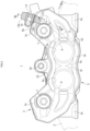
FIG. 1] FIG. 1 is a front view of a disc brake for a vehicle according to a first embodiment of the present invention. - [
FIG. 2] FIG. 2 is a rear view of the same disc brake for a vehicle. - [
FIG. 3] FIG. 3 is a plan view of the same disc brake for a vehicle. - [
FIG. 4] FIG. 4 is a side view of the same disc brake for a vehicle. - [
FIG. 5] FIG. 5 is a cross-sectional view taken along a line V-V inFIG. 4 . - [
FIG. 6] FIG. 6 is a cross-sectional view taken along a line VI-VI inFIG. 1 . - [
FIG. 7] FIG. 7 is a cross-sectional view taken along a line VII-VII inFIG. 2 . - [
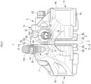
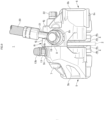
FIG. 8] FIG. 8 is a front view of main portions in a state in which a union bolt and a hose banjo are attached to a union hole. - [
FIG. 9] FIG. 9 is a side view of the state in which the union bolt and the hose banjo are attached to the union hole. - [
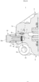
FIG. 10] FIG. 10 is a cross-sectional view taken along a line X-X inFIG. 8 . - [
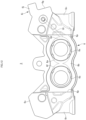
FIG. 11] FIG. 11 is a front view of a caliper body showing the first embodiment of the present invention. - [
FIG. 12] FIG. 12 is a rear view of an opposite-vehicle body-side caliper half body. - [
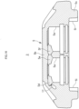
FIG. 13] FIG. 13 is a cross-sectional view taken along a line XIII-XIII inFIG. 11 . - [
FIG. 14] FIG. 14 is a front view of the caliper body on a vehicle body-side. - [
FIG. 15] FIG. 15 is a rear view of a caliper half body on the vehicle body-side. - [
FIG. 16] FIG. 16 is a cross-sectional view taken along a line XVI-XVI inFIG. 15 . - [
FIG. 17] FIG. 17 is a view showing a contouring process. -
FIGS. 1 to 17 are views showing an embodiment of a disc brake for a vehicle using a caliper body formed by a method for producing a caliper half body according to the present invention, in which an arrow A indicates a rotation direction of a disc rotor that rotates integrally with wheels when a vehicle moves forward, and a disc outward-rotation-side and a disc inward-rotation-side to be described later are for when the vehicle moves forward. - A
disc brake 1 for a vehicle of the present embodiment includes adisc rotor 2 that rotates integrally with wheels (not shown) in an arrow A direction, acaliper body 3 attached to a vehicle body on one side of thedisc rotor 2, and a pair offriction pads caliper body 3 in a manner of facing each other with thedisc rotor 2 interposed therebetween. - The
caliper body 3 is formed by integrally coupling, with twocoupling bolts bridge portion 3a straddling an outer peripheral side of thedisc rotor 2. - The vehicle body-side caliper
half body 5 includes an actingportion 5b havingcylinder holes half body 5c that constitutes substantially half of thebridge portion 3a. Similar to the vehicle body-side caliperhalf body 5, the opposite-vehicle body-side caliperhalf body 6 includes an actingportion 6b havingcylinder holes half body 6c that constitutes substantially half of thebridge portion 3a. In addition, a length of the bridgehalf body 6c of the opposite-vehicle body-side caliperhalf body 6 in a disc axial direction is larger than a length of the bridgehalf body 5c of the vehicle body-side caliperhalf body 5 in the disc axial direction. When thecaliper body 3 formed by butt-joining thebridge half bodies joint surface 8 is located on a vehicle body-side with respect to a center CL1 in a width direction of thedisc rotor 2. - In the vehicle body-side caliper
half body 5,pistons cylinder holes hydraulic pressure chambers cylinder holes pistons fluid introduction hole 11 is drilled from a dividing surface serving as thejoint surface 8 on the disc outward-rotation-side of thebridge half body 5c toward thehydraulic pressure chamber 10 of thecylinder hole 5a on the disc outward-rotation-side. A part of a bottom of thecylinder hole 5a on the disc outward-rotation-side includes a first contouring processedportion 5d that allows thehydraulic pressure chamber 10 on the disc outward-rotation-side and the first hydraulicfluid introduction hole 11 to communicate with each other by a contouring process, and a second contouring processedportion 5e that is contoured toward thehydraulic pressure chamber 10 on the disc inward-rotation-side. Further, a part of a bottom of thecylinder hole 5a on the disc inward-rotation-side includes a third contouring processedportion 5f that is contoured toward the second contouring processedportion 5e, and the second contouring processedportion 5e and the third contouring processedportion 5f communicate with each other to form a connection hole, whereby the first hydraulicfluid introduction hole 11, thehydraulic pressure chamber 10 on the disc outward-rotation-side, and thehydraulic pressure chamber 10 on the disc inward-rotation-side communicate with one another. - A
bleeder hole 12 that opens to a disc radial directionouter end surface 5g and communicates with the first hydraulicfluid introduction hole 11 is provided on a disc radial direction outer end on the disc outward-rotation-side of the bridgehalf body 5c. Thebleeder hole 12 is formed with, on an opening side, afemale screw portion 12a into which ableeder screw 13 is screwed, and the disc radial directionouter end surface 5g on an opening outer periphery is formed with amounting seat surface 5h for thebleeder screw 13. Thebleeder screw 13 includes an air discharge hole on an inner peripheral portion thereof and amale screw portion 13a, which is screwed into thefemale screw portion 12a, on an outer peripheral portion thereof, and arubber bleeder cap 13b is covered on a tip head portion. - Similar to the vehicle body-side caliper
half body 5, in the opposite-vehicle body-side caliperhalf body 6,pistons cylinder holes hydraulic pressure chambers cylinder holes pistons fluid introduction hole 16 is drilled from a dividing surface serving as thejoint surface 8 on the disc outward-rotation-side of thebridge half body 6c toward thehydraulic pressure chamber 15 on the disc outward-rotation-side. The first hydraulicfluid introduction hole 11 and the second hydraulicfluid introduction hole 16 communicate with each other at thejoint surface 8, and aseal member 17 is interposed on an outer peripheral side of a communication portion. A part of a bottom of thecylinder hole 6a on the disc outward-rotation-side includes a fourth contouring processedportion 6d that allows thehydraulic pressure chamber 15 on the disc outward-rotation-side and the second hydraulicfluid introduction hole 16 to communicate with each other by a contouring process, and a fifth contouring processedportion 6e that is contoured toward thehydraulic pressure chamber 15 on the disc inward-rotation-side. Further, a part of a bottom of thecylinder hole 6a on the disc inward-rotation-side includes a sixth contouring processedportion 6f that is contoured toward the fifth contouring processedportion 6e, and the fifth contouring processedportion 6e and the sixth contouring processedportion 6f communicate with each other to form a connection hole, whereby the second hydraulicfluid introduction hole 16, thehydraulic pressure chamber 15 on the disc outward-rotation-side, and thehydraulic pressure chamber 15 on the disc inward-rotation-side communicate with one another. - Further, a
union hole 18 that opens to a disc outward-rotation-side end surface 6g and communicates with the second hydraulicfluid introduction hole 16 is provided on a disc outward-rotation-side end of thebridge half body 6c. Theunion hole 18 is formed with, on an opening side, afemale screw portion 18a into which aunion bolt 19 is screwed, and the disc outward-rotation-side end surface 6g on an opening outer periphery is formed with a mountingseat surface 6h for theunion bolt 19. Ahose banjo 21 fixed to an end of abrake pipe 20 is attached to theunion bolt 19, and a rotation-stop portion 6i for thehose banjo 21 is formed on an outer periphery of the mountingseat surface 6h. The rotation-stop portion 6i includes awall portion 6j that protrudes from an outer peripheral side of the mountingseat surface 6h and protects the coupling between theunion bolt 19 and thehose banjo 21, and an engagingportion 6k obtained by cutting out a part of thewall portion 6j to stop rotation of thehose banjo 21, and thehose banjo 21 is not co-rotated when theunion bolt 19 is screwed into theunion hole 18 by clamping thehose banjo 21 with the engagingportion 6k. Theunion bolt 19 includes amale screw portion 19a that is screwed into thefemale screw portion 18a and ahexagonal head portion 19b, a hydraulicfluid communication hole 19c is formed inside themale screw portion 19a, and thebrake pipe 20 communicates with theunion hole 18 via theunion bolt 19. - Radial mount-type vehicle
body mounting portions bolt insertion holes caliper half body 6, and thecaliper body 3 is attached to the vehicle body by screwing mounting bolts inserted into the mountingbolt insertion holes - In the
caliper body 3, the vehicle body-sidecaliper half body 5 and the opposite-vehicle body-sidecaliper half body 6 formed in this manner are joined by thebridge portion 3a and coupled by thecoupling bolts fluid introduction hole 11 and the second hydraulicfluid introduction hole 16 communicate with each other, and accordingly, the first hydraulicfluid introduction hole 11 and the second hydraulicfluid introduction hole 16 communicate with thehydraulic pressure chambers caliper half body 5 and thehydraulic pressure chambers caliper half body 6. Further, theunion hole 18 communicates with the second hydraulicfluid introduction hole 16, and thus a hydraulic fluid is supplied to thehydraulic pressure chambers union bolt 19, the first hydraulicfluid introduction hole 11, and the second hydraulicfluid introduction hole 16. In addition, thebleeder hole 12 communicates with the first hydraulicfluid introduction hole 11, and thus air mixed in the hydraulic fluid introduced into the first hydraulicfluid introduction hole 11, the second hydraulicfluid introduction hole 16, and thehydraulic pressure chambers bleeder screw 13. - The
friction pad 4 includes alining 4a which is in sliding contact with a side surface of thedisc rotor 2, and a metal backplate 4b to which thelining 4a is adhered. A hangingsheet 4c extends from an upper center of theback plate 4b, and ahanger pin 22 is inserted into the hangingsheet 4c. Thehanger pin 22 extends across both the actingportions ceiling opening 3b formed in thebridge portion 3a of thecaliper body 3, and is movable in the disc axial direction betweentorque receiving portions caliper half body 5 and the opposite-vehicle body-sidecaliper half body 6. In addition, apad spring 23 is provided over theback plate 4b, thebridge portion 3a, and thehanger pin 22, and thefriction pads - Next, a method for producing the vehicle body-side
caliper half body 5 of the present embodiment will be described. The vehicle body-sidecaliper half body 5 is formed using a casting material to be used for a vehicle body-side caliper half body to be used in multiple types of disc brake caliper bodies having the same outer shape and different cylinder hole diameters. - As is performed in the related art, the casting material is cast by a gravity casting method using multiple divided outer molds by which an outer shape of the vehicle body-side
caliper half body 5 is formed and a core in which a cylinder hole is formed, and the casting material having pilot holes of two cylinder holes is cast. For the casting material, first, an introduction hole drilling step of drilling the first hydraulicfluid introduction hole 11 from an end surface on the disc outward-rotation-side serving as thejoint surface 8 toward a bottom side of the pilot hole of the cylinder hole on the disc outward-rotation-side is performed. - Next, a cylinder hole cutting step of cutting the pilot holes of the two cylinder holes formed in the casting material into a set diameter of the
cylinder hole 5a is performed, and thecylinder holes portion 5d (communication hole) is formed by performing a contouring process from the bottom side of thecylinder hole 5a on the disc outward-rotation-side toward the first hydraulicfluid introduction hole 11, and the first hydraulicfluid introduction hole 11 and the bottom side of thecylinder hole 5a on the disc outward-rotation-side communicate with each other via the first contouring processedportion 5d. In addition, a connection hole cutting step is performed in which the second contouring processedportion 5e is formed by performing a contouring process from the bottom side of thecylinder hole 5a on the disc outward-rotation-side toward the bottom side of thecylinder hole 5a on the disc inward-rotation-side, the third contouring processedportion 5f is formed by performing a contouring process from the bottom side of thecylinder hole 5a on the disc inward-rotation-side toward the bottom side of thecylinder hole 5a on the disc outward-rotation-side, and the second contouring processedportion 5e and the third contouring processedportion 5f communicate with each other to form the connection hole. - In the contouring process performed in the communication hole cutting step, for example, as shown in (A) of
FIG. 17 , atool 31 is inserted into thecylinder hole 5a to be brought into contact with a bottom of thecylinder hole 5a, and as shown in (B) ofFIG. 17 , thetool 31 is moved to the disc outward-rotation-side of the pilot hole while adrill blade 31a rotates, and a cylindercircumferential groove 32 extending from thecylinder hole 5a to the disc outward-rotation-side is formed. Next, as shown in (C) ofFIG. 17 , thetool 31 is moved in a cylinder axial direction toward a cylinder hole opening side, and a length of the cylindercircumferential groove 32 in the disc axial direction is increased, and as shown in (D) ofFIG. 17 , the first contouring processedportion 5d that allows the first hydraulicfluid introduction hole 11 and the bottom side of thecylinder hole 5a to communicate with each other is formed. - In the contouring process performed in the connection hole cutting step, the
tool 31 is inserted into the pilot hole of onecylinder hole 5a to be brought into contact with the bottom of thecylinder hole 5a, and thetool 31 is moved to the other adjacent cylinder hole side while thedrill blade 31a rotates, and further thetool 31 is inserted into the pilot hole of theother cylinder hole 5a to be brought into contact with the bottom of thecylinder hole 5a, and thetool 31 is moved to the one adjacent cylinder hole side while thedrill blade 31a rotates, whereby the connection hole that connects thecylinder holes - When other vehicle body-side caliper half bodies having the same outer shape as the vehicle body-side
caliper half body 5 and different cylinder hole diameters are produced, the same casting material as the casting material used for producing the vehicle body-sidecaliper half body 5 is used. First, an introduction hole drilling step of drilling a hydraulic fluid introduction hole from an end surface on a disc outward-rotation-side serving as thejoint surface 8 toward a bottom side of a pilot hole of a cylinder hole on the disc outward-rotation-side at the same angle as the first hydraulicfluid introduction hole 11 is performed. - Next, a cylinder hole cutting step of cutting pilot holes of two cylinder holes formed in the casting material into a set cylinder hole diameter is performed, and the cylinder holes having the set diameter are formed in the casting material. Further, a communication hole cutting step is performed in which a first contouring processed portion (communication hole) is formed by performing a contouring process from the bottom side of the cylinder hole on the disc outward-rotation-side toward the hydraulic fluid introduction hole, and the hydraulic fluid introduction hole and the bottom side of the cylinder hole on the disc outward-rotation-side communicate with each other via the first contouring processed portion. In addition, a connection hole cutting step is performed in which a second contouring processed portion is formed by performing a contouring process from the bottom side of the cylinder hole on the disc outward-rotation-side toward the bottom side of the cylinder hole on a disc inward-rotation-side, a third contouring processed portion is formed by performing a contouring process from the bottom side of the cylinder hole on the disc inward-rotation-side toward the bottom side of the cylinder hole on the disc outward-rotation-side, and the second contouring processed portion and the third contouring processed portion communicate with each other to form a connection hole.
- By producing the vehicle body-side caliper half bodies by the above-described method, the multiple vehicle body-side caliper half bodies having the same outer shape and different cylinder hole diameters can be produced by simply changing a cutting amount of the pilot holes of the cylinder holes in the cylinder hole cutting step using the same casting material, and a cost can be reduced. After the cylinder hole is cut into the set diameter in the cylinder hole cutting step, the communication hole that allows the bottom side of the cylinder hole and the first hydraulic fluid introduction hole to communicate with each other is formed by the contouring process in the communication hole cutting step, whereby the communication hole can be easily and reliably formed even when the cylinder hole diameters are different from each other.
- The connection hole that connects the bottom sides of the adjacent cylinder holes is formed by contouring the bottom sides of the cylinder holes arranged side by side in the disc circumferential direction, whereby the connection hole can be easily and reliably formed. In addition, the contouring process for forming the communication hole or the connection hole is applied to a part of the bottoms of the cylinder holes, not the entire circumference, and thus a processing amount can be reduced.
- The multiple types of caliper bodies having different cylinder hole diameters can be provided by producing the multiple types of first caliper half bodies having different cylinder hole diameters by the above-described method and joining them to the second caliper half bodies. Accordingly, the first caliper half bodies can be produced using the same casting mold in the production of the first caliper half bodies, and a production management cost of the caliper body can be reduced.
- The present invention is not limited to the above-described embodiment, and the opposite-vehicle body-side caliper half body may be formed using the same casting material, or both the vehicle body-side caliper half body and the opposite-vehicle body-side caliper half body may be formed using the same casting material. Further, the casting material may be provided with the connection hole formed by the cast hole that connects the bottom sides of the adjacent pilot holes. The vehicle body mounting portion formed in the opposite-vehicle body-side caliper half body may be an axial mount-type vehicle body mounting portion having a mounting bolt insertion hole in the disc axial direction. Further, the number of cylinder holes formed in the caliper half body is any number.
- 1: disc brake for vehicle; 2: disc rotor; 3: caliper body; 3a: bridge portion; 3b: ceiling opening; 4: friction pad; 4a: lining; 4b: back plate; 5: vehicle body-side caliper half body; 5a: cylinder hole; 5b: acting portion; 5c: bridge half body; 5d: first contouring processed portion; 5e: second contouring processed portion; 5f: third contouring processed portion; 5g: disc radial direction outer end surface; 5h: mounting seat surface; 5i: torque receiving portion; 6: opposite-vehicle body-side caliper half body; 6a: cylinder hole; 6b: acting portion; 6c: bridge half body; 6d: fourth contouring processed portion; 6e: fifth contouring processed portion; 6f: sixth contouring processed portion; 6g: disc outward-rotation-side end surface; 6h: mounting seat surface; 6i: rotation-stop portion; 6j: wall portion; 6k: engaging portion; 6m: mounting bolt insertion hole; 6n: vehicle body mounting portion; 6p: torque receiving portion; 7: coupling bolt; 8: joint surface; 9: piston; 10: hydraulic pressure chamber; 11: first hydraulic fluid introduction hole; 12: bleeder hole; 12a: female screw portion; 13: bleeder screw; 13a: male screw portion; 13b: bleeder cap; 14: piston; 15: hydraulic pressure chamber; 16: second hydraulic fluid introduction hole; 17: seal member; 18: union hole; 18a: female screw portion; 19: union bolt; 19a: male screw portion; 19b: hexagonal head portion; 19c: hydraulic fluid communication hole; 20: brake pipe; 21: hose banjo; 22: hanger pin; 23: pad spring; 31: tool; 31a: drill blade; 32: cylinder circumferential groove
Claims (6)
- A method for producing multiple caliper half bodies of a disc brake caliper body, the disc brake caliper body being formed by joining joint surfaces of a pair of caliper half bodies arranged on both sides of a disc rotor with a bridge portion straddling an outer peripheral side of the disc rotor, the method involving producing at least one of the pair of caliper half bodies to be used in multiple types of the disc brake caliper bodies having the same outer shape and different cylinder hole diameters using the same casting material having a pilot hole of a cylinder hole, the method comprising:an introduction hole drilling step of forming an introduction hole configured to allow a hydraulic fluid to be introduced into the cylinder hole in the same casting material by drilling at the same angle from an end surface serving as the joint surface toward a bottom side of the pilot hole;a cylinder hole cutting step of cutting the pilot hole into a cylinder hole diameter set according to the multiple types of disc brake caliper bodies; anda communication hole cutting step of forming a communication hole allowing a bottom side of the cut cylinder hole and the introduction hole to communicate with each other by contouring the bottom side of the cylinder hole.
- The method for producing caliper half bodies of a disc brake caliper body according to claim 1,wherein the same casting material has the multiple pilot holes in a disc circumferential direction,the method further comprising:
a connection hole cutting step of forming, by a contouring process, a connection hole connecting bottom sides of adjacent cylinder holes. - The method for producing caliper half bodies of a disc brake caliper body according to claim 1, wherein
the same casting material has the multiple pilot holes in a disc circumferential direction and a connection hole formed by a cast hole connecting bottom sides of the adjacent pilot holes. - A caliper half body of a disc brake caliper body, the caliper half body being produced by the method for producing caliper half bodies of a disc brake caliper body according to any one of claims 1 to 3, wherein
the communication hole is formed in a semicircular shape. - A caliper half body of a disc brake caliper body, the caliper half body being produced by the method for producing caliper half bodies of a disc brake caliper body according to claim 2, wherein
the connection hole is formed in a semicircular shape. - A method for providing a disc brake caliper body, the method involving providing multiple types of the disc brake caliper bodies having different cylinder hole diameters, the disc brake caliper body being formed by joining a pair of caliper half bodies arranged on both sides of a disc rotor, the method comprising:producing multiple types of first caliper half bodies having different cylinder hole diameters by the method for producing caliper half bodies of a disc brake caliper body according to any one of claims 1 to 3; andjoining the first caliper half bodies and second caliper half bodies.
Applications Claiming Priority (2)
| Application Number | Priority Date | Filing Date | Title |
|---|---|---|---|
| JP2020206561 | 2020-12-14 | ||
| PCT/JP2021/045782 WO2022131200A1 (en) | 2020-12-14 | 2021-12-13 | Method for producing caliper half body of disc brake caliper body, caliper half body of disc brake caliper body, and method for providing disc brake caliper body |
Publications (1)
| Publication Number | Publication Date |
|---|---|
| EP4260964A1 true EP4260964A1 (en) | 2023-10-18 |
Family
ID=82059166
Family Applications (1)
| Application Number | Title | Priority Date | Filing Date |
|---|---|---|---|
| EP21906562.0A Pending EP4260964A1 (en) | 2020-12-14 | 2021-12-13 | Method for producing caliper half body of disc brake caliper body, caliper half body of disc brake caliper body, and method for providing disc brake caliper body |
Country Status (4)
| Country | Link |
|---|---|
| EP (1) | EP4260964A1 (en) |
| JP (1) | JPWO2022131200A1 (en) |
| CN (1) | CN116583368A (en) |
| WO (1) | WO2022131200A1 (en) |
Family Cites Families (4)
| Publication number | Priority date | Publication date | Assignee | Title |
|---|---|---|---|---|
| JP4778978B2 (en) * | 2008-03-21 | 2011-09-21 | 日信工業株式会社 | Caliper body manufacturing method and caliper body for disc brake for vehicle |
| JP5802606B2 (en) * | 2012-05-01 | 2015-10-28 | オークマ株式会社 | Lathe spindle disc brake |
| JP5859916B2 (en) * | 2012-05-29 | 2016-02-16 | 日信工業株式会社 | Manufacturing method of caliper body of disc brake for vehicle |
| JP6983634B2 (en) * | 2017-11-28 | 2021-12-17 | 日立Astemo株式会社 | Disc brake |
-
2021
- 2021-12-13 CN CN202180083890.5A patent/CN116583368A/en active Pending
- 2021-12-13 EP EP21906562.0A patent/EP4260964A1/en active Pending
- 2021-12-13 JP JP2022569977A patent/JPWO2022131200A1/ja active Pending
- 2021-12-13 WO PCT/JP2021/045782 patent/WO2022131200A1/en active Application Filing
Also Published As
| Publication number | Publication date |
|---|---|
| JPWO2022131200A1 (en) | 2022-06-23 |
| CN116583368A (en) | 2023-08-11 |
| WO2022131200A1 (en) | 2022-06-23 |
Similar Documents
| Publication | Publication Date | Title |
|---|---|---|
| US7797812B2 (en) | Method of manufacturing a disc brake | |
| US20100320038A1 (en) | Opposed-piston caliper body | |
| US9488237B2 (en) | Vehicle disc brake caliper body | |
| EP2292369A2 (en) | Cylinder apparatus and disk brake | |
| EP4260964A1 (en) | Method for producing caliper half body of disc brake caliper body, caliper half body of disc brake caliper body, and method for providing disc brake caliper body | |
| EP4253176A1 (en) | Caliper body of disc brake for vehicle | |
| JP2005163810A (en) | Disk brake | |
| TW202043641A (en) | Caliper body for vehicle disc brake | |
| EP4265935A1 (en) | Caliper body for vehicular disc brake | |
| JP2010185501A (en) | Vehicular disc brake | |
| JP4339092B2 (en) | Caliper body manufacturing method | |
| US11085499B2 (en) | Caliper body and disc brake | |
| JP2003148524A (en) | Caliper body for disk brake for vehicle | |
| JP4818336B2 (en) | Caliper body for disc brakes for vehicles | |
| JP3507972B2 (en) | Divided caliper body for vehicle disc brake | |
| CN213768881U (en) | Oil cylinder master pump combination device | |
| CN212744789U (en) | Linkage brake caliper | |
| JP4486796B2 (en) | Caliper body manufacturing method and caliper body for disc brake for vehicle | |
| CN111511615B (en) | Hydraulic unit for generating brake pressure for a hydraulic brake system | |
| JP2021156368A (en) | Caliper body of disc brake for vehicle | |
| JP2005163820A (en) | Caliper body for disc brake for vehicle | |
| KR102363711B1 (en) | Hydraulic unit for generating brake pressure in hydraulic brake system | |
| JP3863870B2 (en) | Split caliper body for vehicle disc brakes | |
| JP2007146955A (en) | Caliper body for vehicular disc brake | |
| CN103758898A (en) | Oil pressure caliper, manufacturing method for oil pressure caliper and manufacturing method for caliper bodies |
Legal Events
| Date | Code | Title | Description |
|---|---|---|---|
| STAA | Information on the status of an ep patent application or granted ep patent |
Free format text: STATUS: THE INTERNATIONAL PUBLICATION HAS BEEN MADE |
|
| PUAI | Public reference made under article 153(3) epc to a published international application that has entered the european phase |
Free format text: ORIGINAL CODE: 0009012 |
|
| STAA | Information on the status of an ep patent application or granted ep patent |
Free format text: STATUS: REQUEST FOR EXAMINATION WAS MADE |
|
| 17P | Request for examination filed |
Effective date: 20230612 |
|
| AK | Designated contracting states |
Kind code of ref document: A1 Designated state(s): AL AT BE BG CH CY CZ DE DK EE ES FI FR GB GR HR HU IE IS IT LI LT LU LV MC MK MT NL NO PL PT RO RS SE SI SK SM TR |
|
| DAV | Request for validation of the european patent (deleted) | ||
| DAX | Request for extension of the european patent (deleted) |