EP4260731A1 - Fermeture de four extensible pour un dispositif à fumer - Google Patents
Fermeture de four extensible pour un dispositif à fumer Download PDFInfo
- Publication number
- EP4260731A1 EP4260731A1 EP22167971.5A EP22167971A EP4260731A1 EP 4260731 A1 EP4260731 A1 EP 4260731A1 EP 22167971 A EP22167971 A EP 22167971A EP 4260731 A1 EP4260731 A1 EP 4260731A1
- Authority
- EP
- European Patent Office
- Prior art keywords
- closure
- oven
- state
- opening
- color
- Prior art date
- Legal status (The legal status is an assumption and is not a legal conclusion. Google has not performed a legal analysis and makes no representation as to the accuracy of the status listed.)
- Pending
Links
Images

Classifications
-
- A—HUMAN NECESSITIES
- A24—TOBACCO; CIGARS; CIGARETTES; SIMULATED SMOKING DEVICES; SMOKERS' REQUISITES
- A24F—SMOKERS' REQUISITES; MATCH BOXES; SIMULATED SMOKING DEVICES
- A24F40/00—Electrically operated smoking devices; Component parts thereof; Manufacture thereof; Maintenance or testing thereof; Charging means specially adapted therefor
- A24F40/40—Constructional details, e.g. connection of cartridges and battery parts
-
- A—HUMAN NECESSITIES
- A24—TOBACCO; CIGARS; CIGARETTES; SIMULATED SMOKING DEVICES; SMOKERS' REQUISITES
- A24F—SMOKERS' REQUISITES; MATCH BOXES; SIMULATED SMOKING DEVICES
- A24F40/00—Electrically operated smoking devices; Component parts thereof; Manufacture thereof; Maintenance or testing thereof; Charging means specially adapted therefor
- A24F40/20—Devices using solid inhalable precursors
Definitions
- the present invention is directed to a closure for an opening of an oven of a smoking device as well as a system comprising an oven with a first opening and such a closure. Furthermore, a method for closing an oven is described.
- reduced-risk or modified-risk devices also known as vaporizers
- vaporizers have become popular as an alternative to traditional tobacco products such as cigarettes, cigars, cigarillos, and rolling tobacco.
- Numerous devices and systems are available on the market. They have in common that in contrast to the traditional products the tobacco is not burned but heated to produce an aerosol and/or vapor for inhalation.
- the substrate is heated in the aerosol generation device.
- Devices of this type generate an aerosol and/or vapor by heating a solid aerosol substrate, typically moist leaf tobacco, to a temperature typically in the range 150°C to 300°C. This temperature has been found advantageous since the substrate is releasing flavor in form of an aerosol but without combusting or burning the substrate.
- the released aerosol and/or vapor is enriched by the components sought by the user. Undesired burnt or bitter taste resulting from combustion and burning the substrate could be avoided. Accordingly, harmful by-products of combustion and burning could be avoided.
- Using of the commercially available aerosol generation devices is often considered not to be very user-friendly. This is mainly caused by the fact, that the substrate to be heated needs to be inserted in a heating chamber.
- This heating chamber (or oven) has to be closable to avoid undesired clogging of the oven with dirt or small objects when the device is not in use and protect integrity of the oven.
- the oven has to be thermally isolated to avoid the risk of user burns. The closure of the oven is moved frequently by the user. Thus, it must be durable but user-friendly.
- a container for an elongate electronic nicotine delivery system or other flavoured vapor delivery system is known.
- the container has a lid that is pivotally attached to a body so that it covers first and ancillary openings in the insert in a closed position.
- a further closure is exemplarily described in the patent application WO 2020/225 102 A1 .
- This closure is moveable relative to an aperture of the device between a closed position in which the closure covers the aperture and an open position in which the aperture is substantially unobstructed by the closure.
- the closure comprises a solid a body and resilient element arranged so as to bias the solid body towards the closed position from a first range of positions and to bias the closure towards an open position from a second range of positions.
- a closure for an opening of an oven according to the present invention comprises a stretchable material.
- a stretchable material is preferably made of an elastic and/or flexible material.
- the material preferably comprises an elastomer. It has been found that such a closure could be very thin. Thus, handling is very easy, and the closure only requires little space. Due to the flexibility of the material, in an open state, the closure could be brought in an advantageous position, in which it does not hinder handling of the device and/or inserting a substrate into the oven.
- the closure is reversibly switchable between a contracted state and a stretched state.
- the length of the closure in a longitudinal direction in the stretched state is greater than in the contracted state. This embodiment is advantageous since in the contracted state the closure requires even less space and handling is even easier.
- the closure comprises a first end which is at least indirectly permanently connected to the oven and a second end, which is at least indirectly detachably connected to the oven.
- the first end is connected to an outer surface of the smoking device.
- the first end could be rotatably connected to the oven and/or the device. This allows rotating the closure away from the aperture of the oven.
- the second end is detachably connected to the oven by a coupling device.
- the coupling device preferably comprises a coupling member selected from a group comprising a hook, a magnet, a hook-and-loop fastener, a button, a loop, an eyelet, an eye and an adhesive.
- the second end could be detachably fixed to the oven.
- the closure covers an aperture of the oven. In this state this aperture is preferably closed in a gastight manner. This ensures that the aerosol could not flow out through this aperture in the closed state.
- the coupling member could be detachably connected to the device at a further position, preferably on the surface of the device.
- the closure is fixed to the device at both ends. This further facilitates handling of the device in a state, in which the aperture of the oven is open.
- a first area of the closure has a first color in its contracted state and a second color, which is different to the first color, in its stretched state.
- the closure covers an aperture of the oven in the stretched state.
- a color of a first area of the closure in which a color of a first area of the closure is different in the contracted state and the stretched state, a user could easily identify by the color of this area, whether the closure is in the stretched state and covers the aperture of the oven correctly.
- the first area could be green in a contracted state, in which the aperture of the oven is accessible, and yellow in a stretched state, in which it covers the aperture of the oven.
- the first area is a surface of the closure, preferably a visible surface, facing away from the oven chamber.
- the first area preferably has a defined pattern, which is preferably selected from a group comprising stripes, circles, a symbol, preferably a symbol indicating an opened or closed state, an alphabetic character and letters. This allows the user to be alerted to the state of the closure in more detail. For example, in a stretched state, the entire visible surface of the closure is yellow. However, only the first area changes its color (for example to yellow) when the closure is brought in the contracted state. Thus, the pattern of the first area becomes recognizable to the user in the contracted state. The pattern could comprise the letters of the word "open" to inform the user about the open state of the closure. However, also other symbols or letters are suitable to inform the user about the state of the closure. In a preferred embodiment, a trademark appears or disappears when the closure is switched from an open state to a closed state or vice versa.
- the length of the closure in a longitudinal directions in the stretched state is greater than in the contracted state by a factor of ⁇ 1,1, preferably ⁇ 1,2, more preferably ⁇ 1,5, most preferably ⁇ 2 and preferably ⁇ 20, preferably ⁇ 15, more preferably ⁇ 10, most preferably ⁇ 5. This ensures that the closure could cover the aperture of the oven in the stretched state and fully uncover the aperture in the contracted state.
- the stretchable material is selected from a group comprising a textile, a silicon and an elastomer, which preferably comprises a strain sensitive material which preferably changes its optical properties depending on the applied strain.
- a strain sensitive material could easily be used to indicate the applied strain, e.g. by a change of color.
- An example for such a material is described by researchers of the University of Connecticut in Nat Commun 7, 11802 (2016 ).
- the invention is also directed to a system comprising an oven having a first opening and a closure as described above for closing this first opening.
- the oven is an electric oven and more preferably an oven of a smoking device.
- a method for closing an oven comprises the steps of:
- the step of fixing an end of the closure at least indirectly to the oven comprises the step of detachably connecting a first connecting member to a second connecting member.
- the first connecting member is preferably selected from a group comprising a hook, a magnet, a hook-and-loop fastener, a button, a loop, an eyelet, an eye and an adhesive.
- the method comprises the step of changing optical properties of a first area of the closure when extending the closure from a contracted state to a stretched state.
- the first area preferably comprises at least one defined pattern, which is more preferably selected from a group comprising a stripe, a circle, a symbol, preferably a symbol indicating an opened or closed state, an alphabetic character, a number and letters.
- the method steps are intended to be carried out using a closure as described above.
- the method in particular relates to using a closure for an opening of an oven as described above.
- all the features of a closure disclosed in combination with the method steps are also preferred embodiments of the above-described closure individually or in combination with other features.
- the above-mentioned closure comprises at least means allowing the method steps (individually and/or in combination) to be performed by a user.
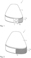
- Fig. 1 shows a schematic view of a device 1 comprising an aperture 2 of an oven 4 in an open state.
- the device 1 comprises a housing 6, which surrounds the oven.
- the housing 6 preferably isolates the oven 4 thermally. Thus, the risk for a user to get in contact with hot surfaces of the oven 4 is reduced.
- a closure 8 For closing the aperture 2 of the oven 4, a closure 8 is provided.
- Fig. 1 the closure is shown in a contracted state.
- the first end 8a is fixed at the housing 6.
- a first color of the closure 8 is indicated in Fig. 1 by the slanted hatching.
- Fig. 2 shows a schematic view of the device 1 as shown in Fig. 1 but in a closed state.
- the aperture 2 of the oven 4 is covered by the closure 8 and is not visible any more in Fig 2 .
- the distance between a first end 8a and a second end 8b of the closure 8 is longer than in Fig. 1 .
- the closure 8 extends from the first end 8a which is fixed to the housing 6, over the aperture (not visible in Fig. 2 ).
- the aperture 2 and the oven 4 are closed by the closure.
- a second color of the closure 8, which is different with respect to the first color, is indicated in Fig. 2 by the cross hatching.
- Fig. 3 shows a schematic view of a device as illustrated in Fig. 1 in a further preferred embodiment in a closed state. Like it is shown in Fig. 2 also in Fig. 3 the aperture 2 of the oven 4 is covered by the closure 8 and is not visible in Fig 3 , too. The closure 8 is extended and the second end 8b of the closure 8 extends over the aperture (not visible in Fig. 3 ). Thus, the aperture 2 and the oven 4 are closed by the closure.
- a second color of the closure 8, which is different with respect to the first color, is indicated in Fig. 2 by the cross hatching.
- Fig. 4 shows a schematic illustration of a schematic illustration of a closure 8 in a contracted state (upper illustration in Fig. 4 ) and an elongated state (lower illustration in Fig. 4 ).
- the lines L1 and L2 indicating a first length L1 and a second length L2
- the length of the closure 8 between a first end 8a and a second end 8b in the elongated state is bigger.
- the color change from a first color (slanted hatching) of the closure 8 to a different second color (cross hatching) is indicated by the different hatchings.
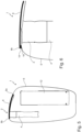
- Fig. 5 is a schematic longitudinal cross-section of a device having an oven 4 and a housing 6 with a closure 8 covering an opening 2 of the oven 4.
- an energy source 12 is visible.
- This energy source is preferably a (rechargeable) battery.
- This battery is electrically connected with the oven 4.
- the oven 4 has an elongated form and an essentially circular cross section. This shape of the oven 4 is advantageous for heating a substrate in form of a stick. Such a stick could be easily inserted through the first opening (or aperture) 2. Due to the circular cross section, a circular stick contacts the hot surfaces of the oven 4 and isolating air between these surfaces and the substrate to be heated could be avoided or reduced.
- Fig. 5 the device is shown in a closed state, in which the closure 8 extends from its first end 8a to its second end 8b over the aperture 2 of the oven 4.
- the closure 8 extends from its first end 8a to its second end 8b over the aperture 2 of the oven 4.
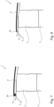
- Fig. 6 is a schematic illustration of a first embodiment of the closure with closing members 14 and 16.
- the second end 8b of the closure 8 can be fixed to the housing 6 of the device 1 by means of a first closing member 14, e.g. a magnetic element 14.
- This magnetic element 14 cold be releasably connected with a complementary element 16, which in this embodiment is a planar surface area 16 of the housing 6.
- the closure 8 covers the aperture 2 and no particles could accidently enter the oven 4.
- a glue or other bonding member 14 could be used as one of the closing members 14 and/or 16.
- the other (second) closing member 16 is configured to releasable bind the first closing member 14.
- Fig. 7 is a schematic illustration of a second embodiment of the closure with closing members 14 and 16.
- the second end 8b of the closure 8 can be fixed to the housing 6 of the device 1 by means of a hook-and-loop fastener 14,16 (e.g. a Velcro ® fastener).
- This hook-and-loop fastener 14, 16 could comprise a first closing member 14 or 16 which comprises (tiny) hooks, whereas the second closing member 14 or 16 features (smaller) loops.
- the closure 8 is not covering the aperture 2 completely, since the first closing member 14 is not yet bound to the second closing member 16. After connection of both closing members 14 and 16 the aperture is securely covers by the closure and no particles could accidently enter the oven 4.
- Fig. 8 is a schematic illustration of a third embodiment of the closure with closing members 14 and 16.
- the closure 8 In the illustrated state, the closure 8 is not yet covering the aperture 2 and the oven 4 completely, since the first closing member 14 is not yet interacting with the second closing member 16.
- the second end 8b of the closure 8 can be fixed to the housing 6 of the device 1 by means of a hook 14 which could mechanically interact with a corresponding protrusion 16 or notch 16. Due to the elasticity of the material of the closure 8, the closure 8 could be further elongated to release the hook 14 from the protrusion 16 or notch 16 and to open the aperture.
- repeatable closure of the oven and its first opening is possible.
Priority Applications (1)
| Application Number | Priority Date | Filing Date | Title |
|---|---|---|---|
| EP22167971.5A EP4260731A1 (fr) | 2022-04-12 | 2022-04-12 | Fermeture de four extensible pour un dispositif à fumer |
Applications Claiming Priority (1)
| Application Number | Priority Date | Filing Date | Title |
|---|---|---|---|
| EP22167971.5A EP4260731A1 (fr) | 2022-04-12 | 2022-04-12 | Fermeture de four extensible pour un dispositif à fumer |
Publications (1)
| Publication Number | Publication Date |
|---|---|
| EP4260731A1 true EP4260731A1 (fr) | 2023-10-18 |
Family
ID=81307487
Family Applications (1)
| Application Number | Title | Priority Date | Filing Date |
|---|---|---|---|
| EP22167971.5A Pending EP4260731A1 (fr) | 2022-04-12 | 2022-04-12 | Fermeture de four extensible pour un dispositif à fumer |
Country Status (1)
| Country | Link |
|---|---|
| EP (1) | EP4260731A1 (fr) |
Citations (6)
| Publication number | Priority date | Publication date | Assignee | Title |
|---|---|---|---|---|
| GB2218894A (en) * | 1988-05-24 | 1989-11-29 | David Thomas Pike | Cover for smokers pipe |
| EP3003073B1 (fr) | 2013-06-04 | 2018-03-21 | Nicoventures Holdings Limited | Contenant |
| WO2020152295A1 (fr) * | 2019-01-25 | 2020-07-30 | Nicoventures Trading Limited | Ensemble destiné à être inséré dans un dispositif de fourniture d'aérosol |
| WO2020176519A1 (fr) * | 2019-02-25 | 2020-09-03 | Fawn Industries, Inc. | Dispositifs du type vaporisateur personnel multi-session, cartouches d'alimentation associées et système de remplissage de cartouche |
| WO2020225102A1 (fr) | 2019-05-03 | 2020-11-12 | Jt International S.A. | Dispositif de génération d'aérosol avec élément de fermeture |
| US20210212363A1 (en) * | 2018-05-25 | 2021-07-15 | Jt International S.A. | Vapour Generating Device and Lid |
-
2022
- 2022-04-12 EP EP22167971.5A patent/EP4260731A1/fr active Pending
Patent Citations (6)
| Publication number | Priority date | Publication date | Assignee | Title |
|---|---|---|---|---|
| GB2218894A (en) * | 1988-05-24 | 1989-11-29 | David Thomas Pike | Cover for smokers pipe |
| EP3003073B1 (fr) | 2013-06-04 | 2018-03-21 | Nicoventures Holdings Limited | Contenant |
| US20210212363A1 (en) * | 2018-05-25 | 2021-07-15 | Jt International S.A. | Vapour Generating Device and Lid |
| WO2020152295A1 (fr) * | 2019-01-25 | 2020-07-30 | Nicoventures Trading Limited | Ensemble destiné à être inséré dans un dispositif de fourniture d'aérosol |
| WO2020176519A1 (fr) * | 2019-02-25 | 2020-09-03 | Fawn Industries, Inc. | Dispositifs du type vaporisateur personnel multi-session, cartouches d'alimentation associées et système de remplissage de cartouche |
| WO2020225102A1 (fr) | 2019-05-03 | 2020-11-12 | Jt International S.A. | Dispositif de génération d'aérosol avec élément de fermeture |
Non-Patent Citations (1)
| Title |
|---|
| NAT COMMUN, vol. 7, 2016, pages 11802 |
Similar Documents
| Publication | Publication Date | Title |
|---|---|---|
| JP7155155B2 (ja) | ケースを備えたエアロゾル発生システム | |
| US5094614A (en) | Miniature self-locking labial bracket | |
| CA2165371C (fr) | Accessoire pour seche-cheveux | |
| USD519275S1 (en) | Carrier for digital player and headphones | |
| US6257250B1 (en) | Hair fashion accessory | |
| JP3121285B2 (ja) | 髪止め具 | |
| US20150327595A1 (en) | Mechanisms for vaporizing devices | |
| JP7356436B2 (ja) | カバー要素を備えるエアロゾル発生装置 | |
| EP4260731A1 (fr) | Fermeture de four extensible pour un dispositif à fumer | |
| CN108783601A (zh) | 一种电子烟具以及电子烟具的取烟方式 | |
| ITVI940016A1 (it) | Chiusura per bracciali, collane e simili. | |
| US4176773A (en) | Holder for cigarette lighter | |
| US7135006B1 (en) | Finger positioner | |
| US20110308048A1 (en) | Clip with magnetic detent for securing lighter to pack of cigarettes | |
| TW202042682A (zh) | 吸煙替代系統 | |
| CN117177680A (zh) | 包括嵌入式加热器的囊体和加热不燃烧(hnb)气溶胶生成装置 | |
| US20020152537A1 (en) | Glove with removable fastener material | |
| US20060174907A1 (en) | Hair holding and containment device | |
| CA3058110A1 (fr) | Ensemble de vapotage | |
| US6202267B1 (en) | Ornamental jewelry catch | |
| JP3127915U (ja) | シャツ襟袖の安定具 | |
| KR20230080409A (ko) | 에어로졸 생성 디바이스를 위한 가열 챔버 | |
| US20140165260A1 (en) | Shirt cuff tips and shirt cuff tip protectors | |
| WO2009019679A1 (fr) | Support de cigarette fixé au doigt permettant de secouer les cendres | |
| US20240000140A1 (en) | Aerosol provision device |
Legal Events
| Date | Code | Title | Description |
|---|---|---|---|
| PUAI | Public reference made under article 153(3) epc to a published international application that has entered the european phase |
Free format text: ORIGINAL CODE: 0009012 |
|
| STAA | Information on the status of an ep patent application or granted ep patent |
Free format text: STATUS: THE APPLICATION HAS BEEN PUBLISHED |
|
| AK | Designated contracting states |
Kind code of ref document: A1 Designated state(s): AL AT BE BG CH CY CZ DE DK EE ES FI FR GB GR HR HU IE IS IT LI LT LU LV MC MK MT NL NO PL PT RO RS SE SI SK SM TR |