EP4259943B1 - Vorrichtung zur mechanischen befestigung am ende eines rohres - Google Patents
Vorrichtung zur mechanischen befestigung am ende eines rohres Download PDFInfo
- Publication number
- EP4259943B1 EP4259943B1 EP20848843.7A EP20848843A EP4259943B1 EP 4259943 B1 EP4259943 B1 EP 4259943B1 EP 20848843 A EP20848843 A EP 20848843A EP 4259943 B1 EP4259943 B1 EP 4259943B1
- Authority
- EP
- European Patent Office
- Prior art keywords
- ring
- tube
- face
- intemal
- diameter
- Prior art date
- Legal status (The legal status is an assumption and is not a legal conclusion. Google has not performed a legal analysis and makes no representation as to the accuracy of the status listed.)
- Active
Links
Images


Classifications
-
- F—MECHANICAL ENGINEERING; LIGHTING; HEATING; WEAPONS; BLASTING
- F16—ENGINEERING ELEMENTS AND UNITS; GENERAL MEASURES FOR PRODUCING AND MAINTAINING EFFECTIVE FUNCTIONING OF MACHINES OR INSTALLATIONS; THERMAL INSULATION IN GENERAL
- F16B—DEVICES FOR FASTENING OR SECURING CONSTRUCTIONAL ELEMENTS OR MACHINE PARTS TOGETHER, e.g. NAILS, BOLTS, CIRCLIPS, CLAMPS, CLIPS OR WEDGES; JOINTS OR JOINTING
- F16B7/00—Connections of rods or tubes, e.g. of non-circular section, mutually, including resilient connections
- F16B7/02—Connections of rods or tubes, e.g. of non-circular section, mutually, including resilient connections with conical parts
- F16B7/025—Connections of rods or tubes, e.g. of non-circular section, mutually, including resilient connections with conical parts with the expansion of an element inside the tubes due to axial movement towards a wedge or conical element
-
- B—PERFORMING OPERATIONS; TRANSPORTING
- B64—AIRCRAFT; AVIATION; COSMONAUTICS
- B64B—LIGHTER-THAN AIR AIRCRAFT
- B64B1/00—Lighter-than-air aircraft
- B64B1/06—Rigid airships; Semi-rigid airships
- B64B1/08—Framework construction
Definitions
- the present invention relates to the technical field of fixing devices anchored to the ends of a tube and intended to create a mechanical connection between the tube and a structure and relates in particular to a mechanical fixing device at the end of a tube.
- tubes are used and in particular cylindrical tubes or rods made of composite material which are particularly resistant to mechanical forces of traction, compression or bending.
- the use of such tubes requires the provision of devices at their end to allow them to be mechanically fixed to another part of the structure.
- Fixing devices such as anchoring or connecting devices located at the ends of a tube comprise threaded sleeves into which the equally threaded ends of the tube are inserted. These devices are generally difficult to implement and require preparation of the end of the tube into which they are inserted.
- fastening devices located at the ends of a tube are made up of parts assembled by gluing.
- the aim of the invention is to overcome the aforementioned drawbacks by providing a fixing device according to claim 1 at the end of a tube allowing simple assembly and disassembly of the parts making up the device while guaranteeing strong and reproducible mechanical anchoring.
- Another object of the invention is to provide an assembly method according to claim 12 of the fixing device according to claim 1.
- the fixing device according to the invention has two embodiments in which it is respectively non-deformable and deformable. These two embodiments are specifically illustrated in the figures 2 to 7 . The description applies to both embodiments unless otherwise specified. In the description, the mention of two references separated by an "or" means that it is the designation of the first embodiment or the second embodiment.
- the fixing device 10 or 100 is shown in an exploded perspective view in section on the Figure 1 .
- the end of a tube 16 with longitudinal axis 5 and its flat end face 26 are also shown in section.
- the fixing device 10 or 100 mainly comprises three parts intended to be assembled to the end of the tube 16: an inner ring 12, a conical insert 14 or 114 and an outer ring 18 or 118.
- the three parts and the tube have the same longitudinal axis represented by the axis 5 in the figures.
- the inner ring 12 has an outer cylindrical wall of diameter equal or substantially equal to the inner diameter of the tube 16 or slightly smaller and a frustoconical inner wall.
- the inner ring 12 comprises a recess 52 in the form of a truncated cone passing from one end to the other of the inner ring and a slot or a plurality of slots 42.
- the inner ring is oriented relative to the tube so that the diameter of its truncated cone-shaped recess 52 narrows towards the end of the tube.
- the slots 42 are made along the generatrices of the inner ring 12 and their plane passes through the longitudinal axis 5 of the inner ring. They are preferably distributed equidistantly around the circumference of the inner ring. As can be seen in the Figure 1 , the slots 42 extend longitudinally over a portion of the length of the inner ring 12.
- the number of slots 42 of the inner ring 12 is a function of its diameter. According to the preferred embodiment of the invention and in particular for an outer diameter of the inner ring 12 of the order of 40 mm, the number of slots 42 is four. The number of slots can be between 1 and 12 without departing from the scope of the invention.
- the inner ring 12 comprises two transverse end faces oriented in transverse planes relative to the longitudinal axis 5.
- a first end face 22 oriented in the same direction as the end face 26 of the tube 16 and a second transverse end face 32.
- the second transverse end face 32 of the inner ring 12 corresponding to its end face where the recess 52 is of larger diameter.
- the fastening device 10 or 100 comprises an outer ring 18 or 118.
- the outer ring 18 or 118 mainly comprises a hollow cylindrical body and a shoulder 28 or 128 in the form of an annular crown which partially closes one end of the ring and which has a circular opening 38 or 138.
- the shoulder 28 or 128 has an inner face 48 or 148 located inside and at the end of the outer ring 18 or 118 and an outer face 58 or 158 located outside and at the end of the outer ring, the faces 48 or 148 and 58 or 158 being flat and annular in shape.
- the fastening device also comprises a conical insert 14 or 114 in the form of a truncated cone whose diameter narrows towards the end of the tube 16.
- the conical insert has a receiving element 56 for a gripping or fastening member.
- the receiving element is a threaded central hole.
- the conical insert could comprise a receiving element in the form of a male part without departing from the scope of the invention.
- the recess 52 in the form of a truncated cone has an angle equal to or less than 1 degree at the most than the angle of the truncated cone.
- the conical insert 14 or 114 has two transverse end faces oriented in planes transverse to the longitudinal axis 5. These two transverse end faces are flat and circular.
- the first transverse face 24 or 124 is that corresponding to the smallest diameter of the conical insert, it is placed on the end side of the tube 16 while the second transverse face of larger diameter of the conical insert is placed on the inside side of the tube 16.
- the receiving element 56 of the conical insert serves to move it using a gripping member such as a tool or a bolt which is screwed inside the threaded hole for example and on which a traction is applied while a force of opposite direction sufficient to keep the fixing device 10 or 100 fixed is applied to the shoulder 28 or 128.
- a gripping member such as a tool or a bolt which is screwed inside the threaded hole for example and on which a traction is applied while a force of opposite direction sufficient to keep the fixing device 10 or 100 fixed is applied to the shoulder 28 or 128.
- the outer ring 18 or 118 allows the tube to be confined so that it can withstand the expansion of the inner ring without cracking.
- the fixing device clamps the tube 16 between the expandable inner ring 12 and the outer ring 18 or 118.
- the expansion of the inner ring 12 frictionally secures the three parts 12, 14 or 114, 18 or 118 and the tube 16.
- the conical insert applies radial and transverse pressure to the inner ring, this pressure is also transmitted to the tube, the outer wall of the inner ring is firmly applied to the inner wall of the tube and the fixing device is locked.
- the conical insert is pushed towards the inside of the tube 16, the pressure is released and the different parts can be disassembled according to a disassembly method which implements the steps of the assembly method in reverse order.
- the fixing device 10 or 100 exerts a transverse pressure on the inner and outer walls of the tube 16 so that the device is held tight on the tube, the conical insert 14 or 114 is then wedged in the inner ring 12 in its assembled position and the fixing device is ready to receive and resist external mechanical forces.
- the expansion of the inner ring 12 is due mainly to elastic deformations, which has the advantage of facilitating the disassembly of the device and its possible reuse.
- the conical insert 14 or 114 has an angle of less than 7° degrees and preferably is between 1° and 5° degrees. These angles have the advantage of being necessary to allow the parts to be disassembled and sufficient to hold the parts together by friction.
- the device according to the invention does not include any glued elements and therefore facilitates the assembly process and limits costs.
- the length of the cylindrical part of the outer ring 18 or 118 is greater than the length of the inner ring 12 so that the length of tube 16 covered by the outer ring 18 or 118 is greater than the length of tube 16 covered by the inner ring 12, the lengths being considered along the longitudinal axis 5.
- This difference in length, noted L1 on the figures 2 And 5 represents between 5% and 15% of the tube length 16 covered by the inner ring 12.
- L1 the difference in length L1 of less than 5%
- a stress concentration phenomenon in the tube section located at the end of the inner ring occurs and can lead to rupture of the tube.
- the outer ring portion beyond 15% no longer supports the expansion of the inner ring.
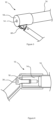
- the fixing device can serve as a connecting piece to fix the last diagonal of a lattice structure on the outer ring 18 and 118 as illustrated in the figures 3 And 6 or on the conical insert 14 and 114.
- the fixing device 10 and 100 comprises a flange 60 fixed on the external wall of the external ring 18 or 118 in order to connect the device 10 or 100 to the lattice beam structure.
- a beam of the lattice structure is directly connected to the fixing device 10 and 100 via example of a screw 36 screwed onto the receiving element 56 of the conical insert 14 and 114.
- the structure can also be fixed onto another part of the device.
- the fixing device 10 or 100 can be used in an aeronautical construction for example in an airship.
- the tube 16 is then one of the main tubes of the end of a lattice beam and the device 10 or 100 thus ensures the connection between the end of the tube 16 and the structure of the airship and also ensures the transfer of the forces applied to the elements constituting the structure which can be very mechanically stressed.
- the torsional forces pass mainly through the surface in contact with the external face 58 of the external ring 18 then through the transverse contact surface 24 of the conical insert with the internal face 58 of the external ring 18.
- the torsional forces pass mainly through the surface in contact with the transverse face 24 of the tapered insert with the face of the beam of the truss structure. If the application requires passing significant torsional forces, standard mechanical elements such as keys or pins can be used to torsionally connect the tapered insert 14 or 114 and the outer ring 18.
- the fixing device 10 of the first embodiment illustrated in the figures 2 to 4 is non-deformable while the fixing device 100 of the second embodiment, illustrated in the figures 5 to 7 , is deformable.
- the conical insert and the outer ring differ according to these two modes on some of their dimensions.
- the conical insert and the outer ring are referenced 14 and 18 while for the deformable fixing device 100, the conical insert and the outer ring are referenced 114 and 118.
- the conical insert 14 and the outer ring are dimensioned so that in their assembled position with the inner ring 12 on the end of the tube 16, the transverse end face 24 of the conical insert 14 is in abutment against the annular inner face 48 of the outer ring 18.
- the smallest diameter of the conical insert 14 is a little larger than the smallest inner diameter of the inner ring 12.
- the difference in diameter is a few tenths of a mm and more precisely this difference in diameter is between 1 and 9 tenths of a millimeter.
- the end face 26 of the tube 16 as well as the transverse end face 22 of the inner ring are also in abutment against the annular inner face 48 of the outer ring 18.
- the width of the shoulder 28 is then arranged so that the circular opening 38 has a sufficient diameter to allow free access to the receiving element 56 of the conical insert 14. According to the embodiments described, the width of the shoulder 28 is therefore arranged so that the circular opening 38 has a diameter greater than the diameter of the threaded central hole 56 of the conical insert 14 and less than the transverse face 24 of the conical insert 14. In this embodiment, the transverse face 24 of the conical insert is in the same plane as the end face 22 of the inner ring 12. In this embodiment, when the device 10 undergoes a tensile load greater than the load for which it was sized, corresponding to the preload, it remains non-deformable until possible rupture.
- the conical insert 114 is in its assembled position, its transverse end face 24 is not in abutment against the internal face 148 of the external ring 118.
- the transverse end face 124 of the conical insert is in the same plane as the external face 158 of the external ring 118.
- the end face 26 of the tube 16 as well as the transverse end face 22 of the internal ring 12 are also in abutment against the annular flat face 148 of the external ring 118.
- the width of the shoulder 128 is then arranged so that the circular opening 138 has a diameter greater than the diameter of the transverse face 124 of the conical insert 114, preferably greater than 0.1 to 2 mm.
- the insert experiences a tensile force greater than the preload, it moves in the longitudinal direction towards the outside of the tube as can be seen illustrated in the Figure 7 where the transverse surface 124 of the conical insert has exceeded the plane 158 of the external face of the ring 118.
- the deformations of the device 100 and in particular the deformations of the internal ring 12 are plastic deformations and will always precede the possible rupture.
- the conical inserts 14 and 114 are dimensioned in such a way that when they are in their assembled position, the devices 10 and 100 have an equivalent preload.
- the three parts of the device are made of the same material, for example metal such as aluminum or an aluminum alloy.
- the coefficient of transverse thermal expansion of the three parts must be substantially equal in order to limit differential expansions due to the different nature of the materials which could intervene and which could disassemble the parts. Indeed, temperature gradients can occur ranging from -30°C to +80°C, or even from -50°C to +85°C. In order to guarantee the functionality of the device for such temperature ranges, the device according to the invention has been tested up to 110°C.
- parts can be made of composite material, particularly carbon fiber composite material.
- the length of the slots 42 on the inner ring 12 is less than the length of the conical insert 14 or 114.
- the slots extend from the transverse face 22 of the inner ring located on the side of the end of the tube and corresponding to the first end of the inner ring, to the vicinity of the other transverse face of the inner ring located at the opposite end of the first, on the tube side. Therefore, one end of the slots 42 all open on the same side outside the ring while the other end is inside the ring. This feature has several advantages.
- the part of the inner ring not split by the slots 42 has a continuous inner annular surface in contact with the conical insert and a continuous outer annular surface in contact with the tube, the continuity of the annular surfaces in contact ensuring the sealing of the device.
- the unsplit annular part of the inner ring expands less than the split part during the assembly step, and makes it possible to reduce over-stresses at the exit of the device in the tube.
- the inner ring 12 comprises two series of longitudinal slots, each series comprising at least two slots.
- the slots of the first series extend from the transverse face 22 of the inner ring located on the side of the end of the tube and corresponding to the first end of the inner ring to the vicinity of the other transverse face 32 of the inner ring, located at the opposite end of the first, without reaching the latter, while the slots of the second series extend in the opposite direction, from the other transverse face 32 of the inner ring to the vicinity of the transverse face 22, but without reaching it.
- the longitudinal slots are regularly spaced on the surface of the inner ring and are arranged so as to alternate a slot of the second series between two slots of the first series.
- the device of the invention is intended for aeronautical use and in particular for the production of airship or aircraft structures. It is particularly well suited to the tubes used for this type of production made of composite material mainly consisting of unidirectional fibers, oriented in the direction of the longitudinal axis of the tube. Indeed, these tubes have the particularity of having a low transverse resistance of the order of 50 to 75 MPa.
- the fixing device and its assembly method could be adapted to other designs requiring a solid and reliable fixing while ensuring a low impact on the mass of the structure on which it is fitted.
Landscapes
- Engineering & Computer Science (AREA)
- General Engineering & Computer Science (AREA)
- Mechanical Engineering (AREA)
- Aviation & Aerospace Engineering (AREA)
- Mutual Connection Of Rods And Tubes (AREA)
Claims (14)
- Befestigungsvorrichtung (10, 100), die durch Zusammenbau von drei Teilen (12, 14 oder 114, 18 oder 118) am Ende eines Rohrs (16) erhalten wird, umfassend:- einen konischen Einsatz (14, 114) in Form eines Kegelstumpfes, dessen Durchmesser sich in Richtung des Endes des Rohrs verjüngt, wobei der konische Einsatz (14, 114) ein Aufnahmeelement (56) für ein Greif- oder Befestigungselement aufweist,- einen Innenring (12), der mit einer kegelstumpfförmigen Aussparung (52) versehen ist, deren Durchmesser sich in Richtung der Mitte des Rohrs verjüngt und deren Winkel gleich oder kleiner als der Kegelstumpfwinkel des konischen Einsatzes ist, wobei die Außenwand des Innenrings zylindrisch ist und einen Durchmesser aufweist, der im Wesentlichen gleich dem Innendurchmesser des Rohrs (16) ist, wobei der Einsatz sich in der Aussparung des Innenrings befindet,einen Außenring (18, 118) mit einem zylindrischen Teil, dessen Innendurchmesser im Wesentlichen gleich dem Außendurchmesser des Rohrs ist, wobei die Innenwand des zylindrischen Teils des Außenrings dazu bestimmt ist, mit der zylindrischen Außenwand des Rohrs (16) in Kontakt zu kommen, wobei der Außenring einen Absatz (28, 128) umfasst, der ein Ende des Außenrings teilweise verschließt und der eine kreisförmige Öffnung (38, 138) aufweist, wobei der Absatz eine ringförmige Innenfläche (48, 148) umfasst, die dazu bestimmt ist, an der Endfläche (26) des Rohrs (16) und an der Querendfläche (22) des auf der Seite des Endes des Rohrs befindlichen Innenrings (12) zur Anlage zu kommen, und eine Außenfläche, die sich an der Außenseite und am Ende des Außenrings befindet,dadurch gekennzeichnet, dass der konische Einsatz (14) und der Außenring (18) so bemessen sind, dass in ihrer zusammengebauten Position mit dem Innenring (12) und dem Rohr (16):entweder eine Querendfläche (24) mit kleinerem Durchmesser des konischen Einsatzes (14) an der Innenfläche (48) des Außenrings (18) anliegt, wobei die kreisförmige Öffnung (38) einen Durchmesser aufweist, der ausreicht, um den Zugang zum Aufnahmeelement (56) freizulassen, und kleiner als der Durchmesser der Querfläche (24) ist,oder die Querendfläche (124) mit dem kleineren Durchmesser des konischen Einsatzes (114) in derselben Ebene wie die Außenfläche (158) des Außenrings (118) liegt.
- Befestigungsvorrichtung nach Anspruch 1, wobei die drei Teile (12, 14 oder 114, 18 oder 118) so bemessen sind, dass ihr Zusammenbau am Ende des Rohrs (16) die Vorrichtung (10 oder 100) fest mit dem Rohr verbindet und in der Lage ist, einer Zugbelastung standzuhalten, die der für den Zusammenbau erforderlichen Belastung entspricht, die als Vorlast bezeichnet wird.
- Befestigungsvorrichtung nach Anspruch 1 oder 2, wobei der Winkel der Aussparung (52) höchstens 1 Grad kleiner ist als der Kegelstumpfwinkel des konischen Einsatzes (14, 114).
- Vorrichtung nach Anspruch 1, 2 oder 3, wobei der Innenring (12) einen Schlitz oder eine Vielzahl von Schlitzen (42) umfasst, die abstandsgleich über den Umfang des Innenrings verteilt sind und sich länglich auf einem Teil der Länge des Innenrings erstrecken.
- Vorrichtung nach einem der Ansprüche 1 bis 4, wobei der konische Einsatz (14, 114) einen Winkel von weniger als 7 Grad und vorzugsweise zwischen 1 und 5 Grad aufweist.
- Vorrichtung nach einem der Ansprüche 1 bis 5, wobei die Länge des zylindrischen Teils des Außenrings (18, 118) größer ist als die Länge des Innenrings (12), so dass die vom Außenring (18, 118) bedeckte Rohrlänge (16) größer ist als die vom Innenring (12) bedeckte Rohrlänge (16), mit einer Länge (L1), die zwischen 5 % und 15 % der vom Innenring (12) bedeckten Rohrlänge (16) darstellt.
- Befestigungsvorrichtung nach einem der Ansprüche 4 bis 6, wobei sich die Schlitze (42) von einer Querfläche (22) des Innenrings (12), die sich auf der Seite des Endes des Rohrs (16) befindet und dem ersten Ende des Innenrings entspricht, bis in die Nähe der anderen Querfläche (32) des Innenrings, die sich am entgegengesetzten Ende des ersten befindet, so dass der Teil des Innenrings (42), der nicht durch die Schlitze geschlitzt ist, eine durchgehende innere ringförmige Oberfläche in Kontakt mit dem konischen Einsatz (14, 114) und eine durchgehende äußere ringförmige Oberfläche in Kontakt mit dem Rohr (16) aufweist, wobei die Durchgängigkeit der in Kontakt stehenden ringförmigen Oberflächen die Dichtheit der Befestigungsvorrichtung (10, 100) gewährleistet.
- Befestigungsvorrichtung nach einem der Ansprüche 4 bis 6, wobei der Innenring (12) zwei Reihen länglicher Schlitze (42) umfasst, wobei jede Reihe mindestens zwei Schlitze (42) umfasst, wobei sich die Schlitze der ersten Reihe von der Querfläche (22) des Innenrings, die sich auf der Seite des Endes des Rohrs befindet und dem ersten Ende des Innenrings entspricht, bis in die Nähe der anderen Querfläche (32) des Innenrings erstrecken, die sich am entgegengesetzten Ende des ersten befindet, während sich die Schlitze der zweiten Reihe in umgekehrter Richtung von der anderen Querfläche (32) des Innenrings bis in die Nähe der Querfläche (22) erstrecken, wobei die länglichen Schlitze so angeordnet sind, dass sich ein Schlitz der zweiten Reihe zwischen zwei Schlitzen der ersten Reihe abwechselt.
- Unverformbare Befestigungsvorrichtung (10) nach einem der Ansprüche 1 bis 8, wobei der kleinste Durchmesser des konischen Einsatzes (14) um einige Zehntel Millimeter größer ist als der kleinste Innendurchmesser des Innenringes (12)und vorzugsweise dieser Durchmesserunterschied zwischen 1 und 9 Zehntel Millimeter beträgt.
- Verformbare Befestigungsvorrichtung (100) nach einem der Ansprüche 1 bis 8, wobei die kreisförmige Öffnung (138) einen Durchmesser aufweist, der größer ist als der Durchmesser der Querfläche (124) mit dem kleineren Durchmesser des konischen Einsatzes (114), vorzugsweise liegt dieser Durchmesserunterschied zwischen 0,1 mm und 2 mm, so dass sich der konische Einsatz (114) in der Längsrichtung zum Äußeren des Rohrs bewegen kann, wenn die Vorrichtung (100) einer Zugbelastung ausgesetzt wird, die höher ist als die, für die sie entsprechend der Vorlast bemessen wurde.
- Befestigungsvorrichtung (10, 100) nach einem der Ansprüche 1 bis 10, wobei die Koeffizienten der thermischen Querausdehnung der drei Teile (12, 14 oder 114, 18 oder 118) im Wesentlichen gleich sind.
- Verfahren zum Zusammenbauen von drei Teilen (12, 14 oder 114, 18 oder 118) am Ende eines Rohrs (16), um die Befestigungsvorrichtung (10, 100) nach einem der Ansprüche 1 bis 11 zu erhalten, umfassend die Schritte, wobei:- der konische Einsatz (14, 114) in die Aussparung (52) des Innenrings (12) so eingepasst wird, dass seine Fläche (24, 124) mit kleinerem Durchmesser durch die Fläche (32) des Innenrings eindringt, die seiner Endfläche entspricht, wo die Aussparung den größeren Durchmesser aufweist, bis der konische Einsatz durch Kontakt mit dem Innenring fixiert ist,- der mit dem konischen Einsatz (14, 114) versehene Innenring (12) in das Rohr (16) gesetzt wird, indem er nach innen gedrückt wird, bis die Endfläche (22) des Innenrings in derselben Ebene wie die Endfläche (26) des Rohrs (16) liegt, wobei die Außenwand des Innenrings (12) zylindrisch ist und einen Durchmesser aufweist, der im Wesentlichen gleich dem Innendurchmesser des Rohrs (16) oder geringfügig kleiner als dieser ist, wobei die zylindrische Außenwand des Innenrings (12) sich dann in Kontakt gegen die Innenwand des Rohrs (16) befindet,- der Außenring (18, 118) so um das Rohr (16) platziert wird, dass die Innenwand seines zylindrischen Teils in Kontakt mit der Außenwand des Rohrs (16) ist und dass die Endoberfläche (26) des Rohrs (16) an der ringförmigen Innenfläche (48, 148) des Außenrings (18, 118) anliegt,- eine Kraft auf den konischen Einsatz (14, 114) ausgeübt wird, um ihn in Richtung des Endes des Rohrs in seine zusammengesetzte Position zu bewegen, wobei der konische Einsatz (14) und der Außenring (18) so bemessen sind, dass sie in ihrer zusammengebauten Position mit dem Innenring (12) und dem Rohr (16):∘ entweder eine Querendfläche (24) mit kleinerem Durchmesser des konischen Einsatzes (14) oder an der Innenfläche (48) des Außenrings (18) anliegt, wobei die kreisförmige Öffnung (38) einen Durchmesser aufweist, der ausreicht, um den Zugang zum Aufnahmeelement (56) freizulassen, und kleiner als der Durchmesser der Querfläche (24) ist.∘ oder die Querendfläche (124) mit dem kleineren Durchmesser des konischen Einsatzes (114) in derselben Ebene wie die Außenfläche (158) des Außenrings (118) liegt:- wobei der konische Einsatz (14, 114) während seiner Bewegung einen Radialschub auf die Wand des Innenrings ausübt, der dessen Ausdehnung bewirkt, wobei die aufgebrachte erforderliche Kraft der Vorlast der Befestigungsvorrichtung (10, 100) entspricht und nach dem Zusammenbau an Ort und Stelle bleibt.
- Gitterstruktur, umfassend eine Befestigungsvorrichtung (10, 100) nach einem der Ansprüche 1 bis 11 für den Bau eines Luftfahrzeugs wie eines Luftschiffs, wobei das Rohr (16) eines der Hauptrohre des Endes eines Fachwerkträgers ist.
- Gitterstruktur nach Anspruch 13, dadurch gekennzeichnet, dass die Befestigungsvorrichtung (10, 100) eine an der Außenwand des Außenrings (18, 118) befestigte Klammer (60) umfasst, um die Vorrichtung (10, 100) mit der Fachwerkträgerstruktur zu verbinden.
Applications Claiming Priority (1)
| Application Number | Priority Date | Filing Date | Title |
|---|---|---|---|
| PCT/FR2020/052362 WO2022123124A1 (fr) | 2020-12-09 | 2020-12-09 | Dispositif de fixation mecanique a l'extremite d'un tube |
Publications (2)
| Publication Number | Publication Date |
|---|---|
| EP4259943A1 EP4259943A1 (de) | 2023-10-18 |
| EP4259943B1 true EP4259943B1 (de) | 2025-06-04 |
Family
ID=74494939
Family Applications (1)
| Application Number | Title | Priority Date | Filing Date |
|---|---|---|---|
| EP20848843.7A Active EP4259943B1 (de) | 2020-12-09 | 2020-12-09 | Vorrichtung zur mechanischen befestigung am ende eines rohres |
Country Status (4)
| Country | Link |
|---|---|
| US (1) | US20240026912A1 (de) |
| EP (1) | EP4259943B1 (de) |
| CA (1) | CA3199532A1 (de) |
| WO (1) | WO2022123124A1 (de) |
Families Citing this family (1)
| Publication number | Priority date | Publication date | Assignee | Title |
|---|---|---|---|---|
| FR3161874A1 (fr) | 2024-05-06 | 2025-11-07 | Duqueine Rhone-Alpes | Fixation mecanique a l’extremite d’un tube composite |
Family Cites Families (6)
| Publication number | Priority date | Publication date | Assignee | Title |
|---|---|---|---|---|
| DE660546C (de) * | 1935-06-18 | 1938-05-28 | Wilhelm Stieber Dr Ing | Loesbare Klemmverbindung zur Verbindung zweier mit Gleitflaechen aufeinandersitzender Koerper |
| CH251206A (fr) * | 1940-01-05 | 1947-10-15 | Nanni Riccardo | Dispositif de serrage à cône et contre-cône. |
| DE29505791U1 (de) * | 1995-04-04 | 1995-06-01 | Hestex Systems B.V., Apeldoorn | Befestigungselement zum lösbaren Verbinden eines Mehrkantrohres |
| BE1009407A3 (fr) * | 1995-06-13 | 1997-03-04 | Cauwenberghe Roger Van | Poteau indicateur. |
| CN104879350A (zh) * | 2015-03-29 | 2015-09-02 | 王朝逊 | 外箍内涨式金属管端口连接组件 |
| IT201800020032A1 (it) * | 2018-12-18 | 2020-06-18 | Politecnico Di Bari | Giunto radiale multiplo |
-
2020
- 2020-12-09 WO PCT/FR2020/052362 patent/WO2022123124A1/fr not_active Ceased
- 2020-12-09 US US18/256,771 patent/US20240026912A1/en active Pending
- 2020-12-09 EP EP20848843.7A patent/EP4259943B1/de active Active
- 2020-12-09 CA CA3199532A patent/CA3199532A1/fr active Pending
Also Published As
| Publication number | Publication date |
|---|---|
| WO2022123124A1 (fr) | 2022-06-16 |
| CA3199532A1 (fr) | 2022-06-16 |
| EP4259943A1 (de) | 2023-10-18 |
| US20240026912A1 (en) | 2024-01-25 |
Similar Documents
| Publication | Publication Date | Title |
|---|---|---|
| EP2259901B1 (de) | Wiederverwendbare vorübergehende befestigungsvorrichtung zur vormontage von mindestens zwei vorab durchlochten bauteilen | |
| EP0024986B1 (de) | Verfahren zum Ausrüsten einer Leitung mit einer Verbindungsmuffe und Verwendung dieser Verbindungsmuffen für die Verbindung von Leitungen | |
| EP0044778B1 (de) | Verbindung für Röhren, insbesondere zur Verwendung in der Petroleumindustrie | |
| EP1950392B1 (de) | Vorrichtung zum Zusammenbau von zwei Einheiten, beispielsweise für den Stator eines Turbotriebwerks | |
| EP0254630B1 (de) | Verbindungsvorrichtung zur schnellen Demontage unter Last | |
| EP2569665B1 (de) | Vorrichtung für den anschluss von schutzrohren eines glasfaserkabels, abschnitt einer optischen übertragungsschaltung mit einer derartigen vorrichtung und versiegelungselement für eine derartige vorrichtung | |
| WO1983001123A1 (fr) | Cellule de centrage pour raccordement de fibres optiques | |
| EP0126698B1 (de) | Montierungsverfahren für ein ringförmiges Element mit einem Rohr aus Aluminium oder einer Aluminiumzusammensetzung | |
| WO2018007324A1 (fr) | Rivet de fixation aveugle avec fût épaulé et procédé d'installation associé | |
| EP4259943B1 (de) | Vorrichtung zur mechanischen befestigung am ende eines rohres | |
| FR2820790A1 (fr) | Procede et dispositif de fixation mecanique d'un composant optique | |
| EP4103855B1 (de) | Längsverstellbare zug-druck-stange mit widerstandsmomentvorrichtung | |
| EP4428430B1 (de) | Tank mit innen- und aussenräumen sowie mindestens einem ringförmigen linearen verbindungssystem zur verbindung dieser behälter | |
| FR3092882A1 (fr) | Dispositif de visualisation de perte de tension dans un assemblage | |
| EP3992476A1 (de) | Abstandshalter und befestigungskit für aussenverkleidungen | |
| FR3026151A1 (fr) | Dispositif d'assemblage a ecrou-barillet, ensemble structurel d'aeronef comprenant un tel dispositif, et procede d'assemblage correspondant | |
| EP2497965B1 (de) | Befestigungsvorrichtung, die mit einem mobilen Klemmelement zum Anpressen gegen eine Mutter der Vorrichtung ausgestattet ist, und Festklemmverfahren der Vorrichtung | |
| FR3002011A1 (fr) | Fixation aveugle avec corps constitue de plusieurs troncons angulaires cylindriques identiques | |
| CA3216499A1 (fr) | Assemblage de tubes diagonaux sur un tube principal d'une poutre treillis en materiau composite | |
| CH627529A5 (en) | Device for coupling mechanical components | |
| FR3115844A3 (fr) | Cheville de maintien et kit de fixation pour parement extérieur | |
| FR2806762A1 (fr) | Dispositif de fixation du type vis-ecrou a desserrage rapide | |
| CH627827A5 (en) | Device for coupling mechanical components | |
| FR2566294A1 (fr) | Procede et dispositif perfectionnes pour l'assemblage d'un tube et d'une tole | |
| FR2732091A3 (fr) | Raccord d'extremite pour un tube flexible |
Legal Events
| Date | Code | Title | Description |
|---|---|---|---|
| STAA | Information on the status of an ep patent application or granted ep patent |
Free format text: STATUS: UNKNOWN |
|
| STAA | Information on the status of an ep patent application or granted ep patent |
Free format text: STATUS: THE INTERNATIONAL PUBLICATION HAS BEEN MADE |
|
| PUAI | Public reference made under article 153(3) epc to a published international application that has entered the european phase |
Free format text: ORIGINAL CODE: 0009012 |
|
| STAA | Information on the status of an ep patent application or granted ep patent |
Free format text: STATUS: REQUEST FOR EXAMINATION WAS MADE |
|
| 17P | Request for examination filed |
Effective date: 20230525 |
|
| AK | Designated contracting states |
Kind code of ref document: A1 Designated state(s): AL AT BE BG CH CY CZ DE DK EE ES FI FR GB GR HR HU IE IS IT LI LT LU LV MC MK MT NL NO PL PT RO RS SE SI SK SM TR |
|
| DAV | Request for validation of the european patent (deleted) | ||
| DAX | Request for extension of the european patent (deleted) | ||
| GRAP | Despatch of communication of intention to grant a patent |
Free format text: ORIGINAL CODE: EPIDOSNIGR1 |
|
| STAA | Information on the status of an ep patent application or granted ep patent |
Free format text: STATUS: GRANT OF PATENT IS INTENDED |
|
| INTG | Intention to grant announced |
Effective date: 20250116 |
|
| GRAS | Grant fee paid |
Free format text: ORIGINAL CODE: EPIDOSNIGR3 |
|
| GRAA | (expected) grant |
Free format text: ORIGINAL CODE: 0009210 |
|
| STAA | Information on the status of an ep patent application or granted ep patent |
Free format text: STATUS: THE PATENT HAS BEEN GRANTED |
|
| AK | Designated contracting states |
Kind code of ref document: B1 Designated state(s): AL AT BE BG CH CY CZ DE DK EE ES FI FR GB GR HR HU IE IS IT LI LT LU LV MC MK MT NL NO PL PT RO RS SE SI SK SM TR |
|
| REG | Reference to a national code |
Ref country code: GB Ref legal event code: FG4D Free format text: NOT ENGLISH |
|
| REG | Reference to a national code |
Ref country code: CH Ref legal event code: EP |
|
| REG | Reference to a national code |
Ref country code: DE Ref legal event code: R096 Ref document number: 602020052413 Country of ref document: DE |
|
| REG | Reference to a national code |
Ref country code: IE Ref legal event code: FG4D Free format text: LANGUAGE OF EP DOCUMENT: FRENCH |
|
| REG | Reference to a national code |
Ref country code: NL Ref legal event code: MP Effective date: 20250604 |
|
| PG25 | Lapsed in a contracting state [announced via postgrant information from national office to epo] |
Ref country code: FI Free format text: LAPSE BECAUSE OF FAILURE TO SUBMIT A TRANSLATION OF THE DESCRIPTION OR TO PAY THE FEE WITHIN THE PRESCRIBED TIME-LIMIT Effective date: 20250604 Ref country code: ES Free format text: LAPSE BECAUSE OF FAILURE TO SUBMIT A TRANSLATION OF THE DESCRIPTION OR TO PAY THE FEE WITHIN THE PRESCRIBED TIME-LIMIT Effective date: 20250604 |
|
| REG | Reference to a national code |
Ref country code: LT Ref legal event code: MG9D |
|
| PG25 | Lapsed in a contracting state [announced via postgrant information from national office to epo] |
Ref country code: GR Free format text: LAPSE BECAUSE OF FAILURE TO SUBMIT A TRANSLATION OF THE DESCRIPTION OR TO PAY THE FEE WITHIN THE PRESCRIBED TIME-LIMIT Effective date: 20250905 Ref country code: NO Free format text: LAPSE BECAUSE OF FAILURE TO SUBMIT A TRANSLATION OF THE DESCRIPTION OR TO PAY THE FEE WITHIN THE PRESCRIBED TIME-LIMIT Effective date: 20250904 |
|
| PG25 | Lapsed in a contracting state [announced via postgrant information from national office to epo] |
Ref country code: PL Free format text: LAPSE BECAUSE OF FAILURE TO SUBMIT A TRANSLATION OF THE DESCRIPTION OR TO PAY THE FEE WITHIN THE PRESCRIBED TIME-LIMIT Effective date: 20250604 |
|
| PG25 | Lapsed in a contracting state [announced via postgrant information from national office to epo] |
Ref country code: BG Free format text: LAPSE BECAUSE OF FAILURE TO SUBMIT A TRANSLATION OF THE DESCRIPTION OR TO PAY THE FEE WITHIN THE PRESCRIBED TIME-LIMIT Effective date: 20250604 |
|
| PG25 | Lapsed in a contracting state [announced via postgrant information from national office to epo] |
Ref country code: HR Free format text: LAPSE BECAUSE OF FAILURE TO SUBMIT A TRANSLATION OF THE DESCRIPTION OR TO PAY THE FEE WITHIN THE PRESCRIBED TIME-LIMIT Effective date: 20250604 |
|
| PG25 | Lapsed in a contracting state [announced via postgrant information from national office to epo] |
Ref country code: RS Free format text: LAPSE BECAUSE OF FAILURE TO SUBMIT A TRANSLATION OF THE DESCRIPTION OR TO PAY THE FEE WITHIN THE PRESCRIBED TIME-LIMIT Effective date: 20250904 |
|
| PG25 | Lapsed in a contracting state [announced via postgrant information from national office to epo] |
Ref country code: LV Free format text: LAPSE BECAUSE OF FAILURE TO SUBMIT A TRANSLATION OF THE DESCRIPTION OR TO PAY THE FEE WITHIN THE PRESCRIBED TIME-LIMIT Effective date: 20250604 |
|
| PG25 | Lapsed in a contracting state [announced via postgrant information from national office to epo] |
Ref country code: NL Free format text: LAPSE BECAUSE OF FAILURE TO SUBMIT A TRANSLATION OF THE DESCRIPTION OR TO PAY THE FEE WITHIN THE PRESCRIBED TIME-LIMIT Effective date: 20250604 |
|
| PG25 | Lapsed in a contracting state [announced via postgrant information from national office to epo] |
Ref country code: PT Free format text: LAPSE BECAUSE OF FAILURE TO SUBMIT A TRANSLATION OF THE DESCRIPTION OR TO PAY THE FEE WITHIN THE PRESCRIBED TIME-LIMIT Effective date: 20251006 |
|
| REG | Reference to a national code |
Ref country code: AT Ref legal event code: MK05 Ref document number: 1800572 Country of ref document: AT Kind code of ref document: T Effective date: 20250604 |
|
| PG25 | Lapsed in a contracting state [announced via postgrant information from national office to epo] |
Ref country code: IS Free format text: LAPSE BECAUSE OF FAILURE TO SUBMIT A TRANSLATION OF THE DESCRIPTION OR TO PAY THE FEE WITHIN THE PRESCRIBED TIME-LIMIT Effective date: 20251004 |
|
| PG25 | Lapsed in a contracting state [announced via postgrant information from national office to epo] |
Ref country code: SM Free format text: LAPSE BECAUSE OF FAILURE TO SUBMIT A TRANSLATION OF THE DESCRIPTION OR TO PAY THE FEE WITHIN THE PRESCRIBED TIME-LIMIT Effective date: 20250604 Ref country code: AT Free format text: LAPSE BECAUSE OF FAILURE TO SUBMIT A TRANSLATION OF THE DESCRIPTION OR TO PAY THE FEE WITHIN THE PRESCRIBED TIME-LIMIT Effective date: 20250604 |
|
| PGFP | Annual fee paid to national office [announced via postgrant information from national office to epo] |
Ref country code: FR Payment date: 20251222 Year of fee payment: 6 |
|
| PG25 | Lapsed in a contracting state [announced via postgrant information from national office to epo] |
Ref country code: CZ Free format text: LAPSE BECAUSE OF FAILURE TO SUBMIT A TRANSLATION OF THE DESCRIPTION OR TO PAY THE FEE WITHIN THE PRESCRIBED TIME-LIMIT Effective date: 20250604 |
|
| PG25 | Lapsed in a contracting state [announced via postgrant information from national office to epo] |
Ref country code: EE Free format text: LAPSE BECAUSE OF FAILURE TO SUBMIT A TRANSLATION OF THE DESCRIPTION OR TO PAY THE FEE WITHIN THE PRESCRIBED TIME-LIMIT Effective date: 20250604 |
|
| PG25 | Lapsed in a contracting state [announced via postgrant information from national office to epo] |
Ref country code: SK Free format text: LAPSE BECAUSE OF FAILURE TO SUBMIT A TRANSLATION OF THE DESCRIPTION OR TO PAY THE FEE WITHIN THE PRESCRIBED TIME-LIMIT Effective date: 20250604 |
|
| PG25 | Lapsed in a contracting state [announced via postgrant information from national office to epo] |
Ref country code: IT Free format text: LAPSE BECAUSE OF FAILURE TO SUBMIT A TRANSLATION OF THE DESCRIPTION OR TO PAY THE FEE WITHIN THE PRESCRIBED TIME-LIMIT Effective date: 20250604 |