EP4259458B1 - Fahrzeugluftreifen mit mittiger umfangsrippe - Google Patents
Fahrzeugluftreifen mit mittiger umfangsrippe Download PDFInfo
- Publication number
- EP4259458B1 EP4259458B1 EP21827595.6A EP21827595A EP4259458B1 EP 4259458 B1 EP4259458 B1 EP 4259458B1 EP 21827595 A EP21827595 A EP 21827595A EP 4259458 B1 EP4259458 B1 EP 4259458B1
- Authority
- EP
- European Patent Office
- Prior art keywords
- circumferential
- contour line
- pneumatic vehicle
- circumferential rib
- snow
- Prior art date
- Legal status (The legal status is an assumption and is not a legal conclusion. Google has not performed a legal analysis and makes no representation as to the accuracy of the status listed.)
- Active
Links
Images


Classifications
-
- B—PERFORMING OPERATIONS; TRANSPORTING
- B60—VEHICLES IN GENERAL
- B60C—VEHICLE TYRES; TYRE INFLATION; TYRE CHANGING; CONNECTING VALVES TO INFLATABLE ELASTIC BODIES IN GENERAL; DEVICES OR ARRANGEMENTS RELATED TO TYRES
- B60C11/00—Tyre tread bands; Tread patterns; Anti-skid inserts
- B60C11/03—Tread patterns
- B60C11/0306—Patterns comprising block rows or discontinuous ribs
-
- B—PERFORMING OPERATIONS; TRANSPORTING
- B60—VEHICLES IN GENERAL
- B60C—VEHICLE TYRES; TYRE INFLATION; TYRE CHANGING; CONNECTING VALVES TO INFLATABLE ELASTIC BODIES IN GENERAL; DEVICES OR ARRANGEMENTS RELATED TO TYRES
- B60C11/00—Tyre tread bands; Tread patterns; Anti-skid inserts
- B60C11/03—Tread patterns
- B60C11/12—Tread patterns characterised by the use of narrow slits or incisions, e.g. sipes
- B60C11/1259—Depth of the sipe
-
- B—PERFORMING OPERATIONS; TRANSPORTING
- B60—VEHICLES IN GENERAL
- B60C—VEHICLE TYRES; TYRE INFLATION; TYRE CHANGING; CONNECTING VALVES TO INFLATABLE ELASTIC BODIES IN GENERAL; DEVICES OR ARRANGEMENTS RELATED TO TYRES
- B60C11/00—Tyre tread bands; Tread patterns; Anti-skid inserts
- B60C11/03—Tread patterns
- B60C2011/0337—Tread patterns characterised by particular design features of the pattern
- B60C2011/0339—Grooves
- B60C2011/0358—Lateral grooves, i.e. having an angle of 45 to 90 degees to the equatorial plane
- B60C2011/036—Narrow grooves, i.e. having a width of less than 3 mm
-
- B—PERFORMING OPERATIONS; TRANSPORTING
- B60—VEHICLES IN GENERAL
- B60C—VEHICLE TYRES; TYRE INFLATION; TYRE CHANGING; CONNECTING VALVES TO INFLATABLE ELASTIC BODIES IN GENERAL; DEVICES OR ARRANGEMENTS RELATED TO TYRES
- B60C11/00—Tyre tread bands; Tread patterns; Anti-skid inserts
- B60C11/03—Tread patterns
- B60C2011/0337—Tread patterns characterised by particular design features of the pattern
- B60C2011/0339—Grooves
- B60C2011/0358—Lateral grooves, i.e. having an angle of 45 to 90 degees to the equatorial plane
- B60C2011/0365—Lateral grooves, i.e. having an angle of 45 to 90 degees to the equatorial plane characterised by width
-
- B—PERFORMING OPERATIONS; TRANSPORTING
- B60—VEHICLES IN GENERAL
- B60C—VEHICLE TYRES; TYRE INFLATION; TYRE CHANGING; CONNECTING VALVES TO INFLATABLE ELASTIC BODIES IN GENERAL; DEVICES OR ARRANGEMENTS RELATED TO TYRES
- B60C11/00—Tyre tread bands; Tread patterns; Anti-skid inserts
- B60C11/03—Tread patterns
- B60C2011/0337—Tread patterns characterised by particular design features of the pattern
- B60C2011/0339—Grooves
- B60C2011/0358—Lateral grooves, i.e. having an angle of 45 to 90 degees to the equatorial plane
- B60C2011/0367—Lateral grooves, i.e. having an angle of 45 to 90 degees to the equatorial plane characterised by depth
- B60C2011/0369—Lateral grooves, i.e. having an angle of 45 to 90 degees to the equatorial plane characterised by depth with varying depth of the groove
-
- B—PERFORMING OPERATIONS; TRANSPORTING
- B60—VEHICLES IN GENERAL
- B60C—VEHICLE TYRES; TYRE INFLATION; TYRE CHANGING; CONNECTING VALVES TO INFLATABLE ELASTIC BODIES IN GENERAL; DEVICES OR ARRANGEMENTS RELATED TO TYRES
- B60C11/00—Tyre tread bands; Tread patterns; Anti-skid inserts
- B60C11/03—Tread patterns
- B60C2011/0337—Tread patterns characterised by particular design features of the pattern
- B60C2011/0386—Continuous ribs
- B60C2011/0388—Continuous ribs provided at the equatorial plane
-
- B—PERFORMING OPERATIONS; TRANSPORTING
- B60—VEHICLES IN GENERAL
- B60C—VEHICLE TYRES; TYRE INFLATION; TYRE CHANGING; CONNECTING VALVES TO INFLATABLE ELASTIC BODIES IN GENERAL; DEVICES OR ARRANGEMENTS RELATED TO TYRES
- B60C11/00—Tyre tread bands; Tread patterns; Anti-skid inserts
- B60C11/03—Tread patterns
- B60C11/12—Tread patterns characterised by the use of narrow slits or incisions, e.g. sipes
- B60C11/1204—Tread patterns characterised by the use of narrow slits or incisions, e.g. sipes with special shape of the sipe
- B60C2011/1213—Tread patterns characterised by the use of narrow slits or incisions, e.g. sipes with special shape of the sipe sinusoidal or zigzag at the tread surface
-
- B—PERFORMING OPERATIONS; TRANSPORTING
- B60—VEHICLES IN GENERAL
- B60C—VEHICLE TYRES; TYRE INFLATION; TYRE CHANGING; CONNECTING VALVES TO INFLATABLE ELASTIC BODIES IN GENERAL; DEVICES OR ARRANGEMENTS RELATED TO TYRES
- B60C11/00—Tyre tread bands; Tread patterns; Anti-skid inserts
- B60C11/03—Tread patterns
- B60C11/12—Tread patterns characterised by the use of narrow slits or incisions, e.g. sipes
- B60C11/1259—Depth of the sipe
- B60C2011/1268—Depth of the sipe being different from sipe to sipe
-
- B—PERFORMING OPERATIONS; TRANSPORTING
- B60—VEHICLES IN GENERAL
- B60C—VEHICLE TYRES; TYRE INFLATION; TYRE CHANGING; CONNECTING VALVES TO INFLATABLE ELASTIC BODIES IN GENERAL; DEVICES OR ARRANGEMENTS RELATED TO TYRES
- B60C11/00—Tyre tread bands; Tread patterns; Anti-skid inserts
- B60C11/03—Tread patterns
- B60C11/12—Tread patterns characterised by the use of narrow slits or incisions, e.g. sipes
- B60C2011/129—Sipe density, i.e. the distance between the sipes within the pattern
-
- B—PERFORMING OPERATIONS; TRANSPORTING
- B60—VEHICLES IN GENERAL
- B60C—VEHICLE TYRES; TYRE INFLATION; TYRE CHANGING; CONNECTING VALVES TO INFLATABLE ELASTIC BODIES IN GENERAL; DEVICES OR ARRANGEMENTS RELATED TO TYRES
- B60C11/00—Tyre tread bands; Tread patterns; Anti-skid inserts
- B60C11/03—Tread patterns
- B60C11/13—Tread patterns characterised by the groove cross-section, e.g. for buttressing or preventing stone-trapping
- B60C11/1307—Tread patterns characterised by the groove cross-section, e.g. for buttressing or preventing stone-trapping with special features of the groove walls
- B60C2011/133—Tread patterns characterised by the groove cross-section, e.g. for buttressing or preventing stone-trapping with special features of the groove walls comprising recesses
Definitions
- the invention relates to a pneumatic vehicle tire with a tread having a profile.
- the profile of the tread has two circumferential grooves running around the entire tire.
- a central circumferential rib of the profile is delimited by two mutually parallel sides of these two circumferential grooves, which run perpendicular to the axial direction A of the pneumatic vehicle tire.
- This circumferential rib has fine cuts at a regular distance in the circumferential direction, which run from one to the other of the mutually parallel sides of the two circumferential grooves along a contour line.
- Pneumatic vehicle tires suitable for use in winter usually called winter tires for short, must keep a vehicle stable on a road even when it is covered in snow or ice.
- this winter performance which includes snow and ice performance, also includes safe cornering with the vehicle, as well as safe starting and braking with the vehicle.
- the tread of the pneumatic vehicle tire has a correspondingly designed profile.
- the rubber-snow friction of a pneumatic vehicle tire is determined by the rubber material of the tread, in particular by the rubber material on the surface of the tread.
- the profile of the tread of the pneumatic vehicle tire has structures such as grooves that fill with snow picked up from the road. This is known from the WO 2018/103924 A1 , the circumferential grooves with a depth of 1.5 mm to 2.5 mm and a width 2.0 to 3.0 times this depth fill quickly and reliably with snow when driving on a snow-covered road.
- Rapidly filling a structure in the profile of the vehicle's pneumatic tire with snow to generate snow-snow friction is particularly important when a vehicle has an anti-skid control system (ASR system) or an anti-lock braking system (ABS), since then after short slip distances or short intervention times the profile of the vehicle's pneumatic tire comes into engagement with the road and snow-snow friction is then required for this.
- ASR system anti-skid control system
- ABS anti-lock braking system
- the edge (shear) effect of the profile structure is achieved with fine incisions, also known as sipes, at regular intervals in the profile.
- the width of these fine incisions is smaller than the width of grooves or grooves in the profile of the tread of a pneumatic vehicle tire and is between 0.2 mm and 0.7 mm, preferably between 0.4 and 0.6 mm and particularly preferably between 0.45 mm and 0.55 mm.
- the fine incisions are typically arranged in the profile blocks of the tread profile, which are formed by grooves in the profile. If a profile block now passes through the ground contact area of the pneumatic vehicle tire, i.e.
- the profile block is in contact with the road during tire rotation, the fine incisions in the profile block open up and grip edges are created that increase the power transmission in the snow.
- the profile block elements delimited by two fine incisions or one fine incision and one profile block edge tilt. The formation of the grip edges and the tilting of the profile block elements increases with the depth of the fine cuts in the profile.
- the depth T F of the fine incisions can be reduced at the block edges, e.g. to improve the handling of the pneumatic vehicle tire.
- Such structures of the fine incisions known as edge elevation of the fine incisions, on the other hand reduce the formation of the grip edges and the tilting of the tread block elements.
- the tilting of the tread block element is disadvantageous because, when a tread block passes through the ground contact area, the contact area between the tread block elements present in the tread block and the icy road is reduced, so that only a reduced contact area can contribute to the power transmission between the vehicle's pneumatic tire and the road.
- This conflicting objective of snow and ice performance in snow and ice contact can be taken into account by providing a band profile in a circumferential rib of the profile of the vehicle pneumatic tire tread.
- the circumferential rib runs once around the tire circumference and has a fixed position in the axial direction A of the vehicle pneumatic tire.
- the axial direction A of the vehicle pneumatic tire is the direction of the axis around which the vehicle pneumatic tire mounted on a rim rotates in a vehicle. Accordingly, such a circumferential rib is delimited by two circumferential grooves in the axial direction A.
- the side of these circumferential grooves that delimit the circumferential rib then preferably run parallel to one another and preferably run in the circumferential direction perpendicular to the axial direction A.
- the circumferential rib as a band profile has a fine cut at a regular distance in the circumferential direction. Since such a circumferential rib does not have any profile blocks separated by grooves, particularly transverse grooves transverse to the circumferential direction, the tilting of the rib elements formed by the fine incisions in the circumferential rib is reduced as they pass through the ground contact surface. On the other hand, the rib elements support each other so well that the fine incisions no longer open up so wide that the gripping edges created by them develop their full effect in snow. Snow-snow friction is also reduced with such a Circumferential rib is only slightly pronounced and is based only on the circumferential grooves with full tread depth that border it.
- the circumferential rib is positioned centrally in the axial direction A and preferably centrally.
- a circumferential rib is central if there are other profile elements such as profile blocks between the circumferential rib and the tire shoulder that is closer to it in the axial direction A.
- a circumferential rib is a central circumferential rib if it is positioned centrally in the axial direction A in the tread of the pneumatic vehicle tire and the sides of the two circumferential grooves that border it are at the same distance from the tire shoulder that is closer in the axial direction A.
- a central circumferential rib which has a straight fine cut angled to the axial direction A at regular intervals in the circumferential direction, and where instead of a fine cut eight times the length of the distance between the fine cuts in the circumferential direction, a thin transverse groove angled to the axial direction A is arranged in the central circumferential rib.
- These transverse grooves have a depression in their end regions which is greater than the depth of the transverse groove and has the same depth as the circumferential grooves which delimit the circumferential rib.
- the sides of these circumferential grooves which delimit the circumferential rib limit have a zigzag shape with respect to the axial direction A and do not run parallel to each other.
- Circumferential ribs in the shoulder area of a pneumatic vehicle tire which have a fine cut at regular intervals in the circumferential direction, with every fifth fine cut in the circumferential direction the end areas having a groove section which has a greater width than the fine cut and a greater depth than the fine cut.
- the groove sections are intended to fill with snow when driving on a snow-covered road.
- Such a pneumatic vehicle tire has a tread with a profile that has a central circumferential rib that is delimited by two sides that run at least almost parallel to one another of two circumferential grooves that run around the entire pneumatic vehicle tire and that run at least almost perpendicular to the axial direction A of the pneumatic vehicle tire, in that they only deviate from the radial direction of a plane perpendicular to the axial direction A by an angle y that is less than 15 °, such that the width of the circumferential rib remains constant or increases with increasing tread depth, wherein the circumferential rib has a fine cut at a regular distance d in the circumferential direction that runs from one to the other of the sides of the two circumferential grooves that run parallel to one another along a contour line, and wherein instead of a fine cut at three to seven times the length of the distance d of the fine cuts in the circumferential direction, a thin transverse groove is arranged in the central circumferential rib, the width B Q of which is at
- a pneumatic vehicle tire according to the invention therefore has a tread with a profile that has two circumferential grooves running around the entire tire.
- the two circumferential grooves are adjacent circumferential grooves, between which there is a central circumferential rib in the tread.
- Each circumferential groove of a pneumatic vehicle tire has two sides in the axial direction A of the pneumatic vehicle tire, if its cross-section is viewed perpendicular to the circumferential direction.
- the two sides are located in relation to the deepest point of the cross-section of the circumferential groove, whose distance from the surface of the tread corresponds to the profile depth of the pneumatic vehicle tire, in the axial direction A on one side or the other of the deepest point of the cross-section.
- Both sides of the circumferential groove delimit a circumferential rib made of the rubber material of the tread.
- the sides of two adjacent circumferential grooves facing each other then together delimit a circumferential rib of the profile of the tread.
- the sides of the two circumferential grooves that delimit the circumferential rib run at least almost parallel to one another and at least almost perpendicular to the axial direction A of the pneumatic vehicle tire.
- the sides that delimit the circumferential rib only deviate from the radial direction of a plane perpendicular to the axial direction A by an angle ⁇ that is less than 15 °. This deviation of the sides that delimit the circumferential rib is such that the width of the circumferential rib remains constant or increases with increasing tread depth.
- Both sides that delimit the circumferential rib therefore run parallel to the circumferential direction of the pneumatic vehicle tire and only have the slight deviation from the radial direction of the pneumatic vehicle tire given by the angle ⁇ .
- the radial direction of the pneumatic vehicle tire is perpendicular to its axial direction A, around which it rotates.
- the tread depth of the tire profile increases.
- the sides delimiting the circumferential rib now deviate by the angle ⁇ from the radial direction of the pneumatic vehicle tire, so that the width of the circumferential rib remains constant or increases with increasing profile depth, i.e. inwards.
- the circumferential rib then has a constant width B in the axial direction A over the entire circumference of the pneumatic vehicle tire according to the invention on the surface and at every profile depth, which is given by the distance between the at least almost parallel sides in the axial direction, but which varies according to the angle y, which is Tread depth varies, can increase towards the inside.
- the two sides of the two parallel circumferential grooves which delimit the circumferential rib lie in two parallel planes which are perpendicular to the axial direction A. Then, apart from the bottom region of the circumferential grooves, the angle ⁇ is constant over the tread depth 0 and the width B over the tread depth of the tread.
- the two circumferential grooves themselves which delimit the circumferential rib also run parallel to one another in two planes perpendicular to the axial direction A, i.e. the deepest point of the cross-section of the circumferential grooves perpendicular to the circumferential direction is located over the entire circumference of the tire in one of the two planes perpendicular to the axial direction A. It is particularly preferred for both circumferential grooves to have the same width in the axial direction A over the entire circumference of the tire. Pure manufacturing tolerances when producing the tire tread are not taken into account here with regard to the design of the circumferential grooves.
- the width B in the axial direction A of the circumferential rib on its surface in the new condition of the pneumatic vehicle tire is 17 mm to 40 mm, preferably 20 mm to 30 mm and particularly preferably 22 mm to 28 mm.
- the circumferential rib has a fine cut at a regular distance d in the circumferential direction.
- the fine cuts in the circumferential rib run from one to the other of the parallel sides of the two circumferential grooves that delimit the circumferential rib along a contour line.
- the fine cuts therefore run from one end of the circumferential rib in the axial direction A, which is formed by one side of one of the two circumferential grooves, to the other end of the circumferential rib in the axial direction A, which is formed by one side of the second of the two circumferential grooves. All fine cuts run along a defined contour line, which also runs from one end of the circumferential rib in the axial direction A to the other end of the circumferential rib in the axial direction A.
- the contour line defines the course of the fine cuts on the surface of the tread, regardless of the circumferential position of the fine cut. This is the Contour line only around the main line along which the fine incisions run from one end of the circumferential rib to the other end of the circumferential rib.
- the actual course of the fine incision on the surface of the tread can deviate from this main line, since a course of the fine incision to the main line can be added, which essentially has a component perpendicular to the main line in the surface of the tread, i.e. which runs mainly perpendicular to the contour line in the surface of the tread.
- the dimension of the deviation from the main line is significantly smaller than the width B of the circumferential rib in the axial direction A.
- the dimension of the deviation is a maximum of 15% of the width B of the circumferential rib, preferably a maximum of 5% of the width B of the circumferential rib and particularly preferably 3% of the width B of the circumferential rib.
- the course supplemented in this way has its main component, i.e. its main course direction, in a direction which typically does not deviate by more than 20° from the perpendicular to the contour line in the surface of the tread, preferably does not deviate by more than 5° from the perpendicular to the contour line in the surface of the tread and particularly preferably does not deviate by more than 2° from the perpendicular to the contour line in the surface of the tread.
- the supplemented course oscillates or meanders around the contour line in the direction of the main component or has a zigzag course or other periodic course in this direction, wherein the period can vary along the contour line.
- the supplemented course is preferably only present over part of the contour line.
- the fine incisions extend from the surface of the circumferential rib in the radial direction of the pneumatic vehicle tire to a depth T F , following their course on the surface of the tread. In the circumferential direction, adjacent fine incisions have almost the same distance d n in the circumferential direction and preferably run parallel to one another.
- the distance d n of adjacent fine incisions in the circumferential direction varies over the entire tire circumference typically by a maximum of 10% of the average distance d, preferably by a maximum of 5% of the average distance d and particularly preferably by a maximum of 2% of the average distance d. This is based in particular only on manufacturing tolerances in the context of the manufacture of the pneumatic vehicle tire.
- the regular distance d in the circumferential direction of the fine incisions on the Surface of the circumferential rib in the new condition of the pneumatic vehicle tire 3 mm to 9 mm, preferably 4 mm to 7 mm and particularly preferably 5 mm to 6 mm.
- a thin transverse groove is arranged in the circumferential rib of the pneumatic vehicle tire according to the invention at a length three to seven times the distance d of the fine incisions in the circumferential direction.
- These thin transverse grooves can each be arranged at the same distance or preferably at different distances in the circumferential direction in the circumferential groove, the distance of the thin transverse grooves in the circumferential direction being a multiple of the distance d of the fine incisions in the circumferential direction.
- the width B Q of the thin transverse groove in the central circumferential rib of the pneumatic vehicle tire according to the invention is at least 2.5 times as large as the width B F of a sipe in the central circumferential rib, preferably 2.5 to 5 times as large as the width B F of a sipe, particularly preferably 2.75 to 4.5 times as large as the width B F of a sipe and extremely preferably 2.8 to 4 times as large as the width B F of a sipe.
- the width B Q of the thin transverse grooves and the width B F of the sipes is the width perpendicular to the common contour line of the thin transverse grooves and sipes.
- the thin transverse grooves in the central circumferential rib of the pneumatic vehicle tire according to the invention have the contour line of the fine incisions.
- the transverse grooves and fine incisions of the central circumferential rib have essentially the same shape on the surface of the tread of a vehicle tire according to the invention.
- the thin transverse grooves therefore follow the same contour line as the fine incisions.
- the contour line of a thin transverse groove and a adjacent fine sipes are offset by the distance d in the circumferential direction and parallel to one another. It is important that each thin transverse groove runs along the contour line and not, as a fine sipe can also have an additional course which essentially has a component perpendicular to the contour line.
- the thin transverse grooves extend from the surface of the circumferential rib in the radial direction of the pneumatic vehicle tire to a depth T Q , following their course on the surface of the tread.
- the depth T F of the fine incisions of the central circumferential rib of the pneumatic vehicle tire according to the invention is at least partially reduced over a length L red of the contour line in the end regions of the fine incisions.
- the depth T F of such a fine incision is thus limited to a reduced depth T F,1 in one end region or both end regions of the fine incision that are adjacent to the two circumferential grooves delimiting the circumferential rib.
- Such a fine incision then has one edge elevation or two edge elevations. Only some of the fine incisions of the central circumferential rib can have one or two such edge elevations, or all of the fine incisions can have them.
- the reduction in the depth T F can be the same for all fine incisions with edge elevation or it can be different.
- the length L red of the contour line in which an edge elevation is present begins at one end of the surface of the circumferential rib in the axial direction A, i.e. at one of the two sides of one of the two circumferential grooves that delimit the circumferential rib, and then ends at a certain point on the contour line.
- the thin transverse grooves of the circumferential rib have a snow pocket in their end areas over almost the same or a greater length L S , namely over 80% to 250% of this length L red of the contour line.
- the purpose of such a snow pocket, which forms a cavity in the tire profile is to quickly fill with snow from the road while driving, so that an increased snow grip occurs accordingly quickly due to the snow-snow friction.
- the snow pockets at the ends of the thin transverse grooves have a width B S perpendicular to the contour line of the thin transverse grooves, which is determined parallel to the tire surface in which the contour line runs, which is at least 1.5 times as large as the width B Q of the thin transverse groove, and a depth T S that is a maximum of 65% of the tread depth T Q of the thin transverse groove.
- the other geometric dimensions of the snow pockets provided in the central circumferential rib of a pneumatic vehicle tire according to the invention are thus coupled to the dimensions of the thin transverse grooves in the circumferential rib.
- the depth T S of the snow pockets and the tread depth T Q of the thin transverse grooves each indicate the extent of the snow pockets or thin transverse grooves in the radial direction of the pneumatic vehicle tire starting from the surface of the tread of the pneumatic vehicle tire.
- snow pockets are provided at the ends of thin transverse grooves that run from one side of the circumferential rib to the other, which have a lateral extent, i.e. parallel to the tire surface, which is given by a length Ls along the contour line of the associated thin transverse groove and a width Bs perpendicular to the contour line.
- the width B S is deliberately increased compared to the width B Q of the thin transverse groove and the length L S is selected to be similar in dimension or a certain amount larger than the length L red of the edge elevations of the fine incisions of the circumferential rib.
- the snow pockets have a large cross-sectional area on the groove surface, which can fill with snow when driving on a snow-covered road.
- the limited depth Ts of the snow pockets requires a quick Filling the snow bag with snow so that increased snow grip is quickly achieved through snow-snow friction.
- Such an intervention is particularly advantageous when a vehicle has an anti-skid control system (ASR) or an anti-lock braking system (ABS) and is therefore able to quickly take advantage of the improved friction.
- ASR anti-skid control system
- ABS anti-lock braking system
- the length Ls of the snow pockets which is over 80% to 250% of the length L red of the edge elevations of the fine cuts along the contour line, has almost the same dimension as the length L red of the edge elevations or is greater than the length L red of the edge elevations.
- the snow pockets are therefore specifically positioned in the same position in the axial direction as the edge elevations of the fine cuts, since the snow pockets act as cavities to counteract a stiffening of the circumferential rib in this axial position, i.e. at their ends in the axial direction A, by the edge elevations and thus the circumferential stiffness, i.e. the elasticity of the circumferential rib, is evened out in the axial direction A. This promotes more even wear of the tread of a pneumatic vehicle tire according to the invention. This evening out is based on all dimensions of the snow pockets, i.e. in addition to their length L S, also their width B S and their depth T S .
- both the snow-snow friction of a pneumatic vehicle tire and, at the same time, the abrasion behavior of the pneumatic vehicle tire can be improved.
- the central circumferential rib of the pneumatic vehicle tire according to the invention is its central circumferential rib. In this position, the circumferential rib is in direct contact with the road at least most of the time during driving, so that the snow pockets in the circumferential direction are then most reliably filled with snow quickly on a snow-covered road and the snow-snow friction builds up accordingly quickly.
- the thin transverse grooves are arranged in the circumferential direction in the central circumferential groove of the pneumatic vehicle tire according to the invention over different multiples of the distance d of the fine cuts instead of a fine cut.
- the acoustic behavior of the pneumatic vehicle tire according to the invention is improved by arranging the thin transverse grooves at different distances over the tire circumference, whereby the sequence of the different multiples can nevertheless repeat periodically over the tire circumference.
- the sequence of multiples can, for example, consist of exactly two different multiples, e.g. fourfolds and fivefolds, which repeat irregularly or regularly.
- every fourth or fifth fine cut is then replaced by a thin transverse groove, which has a snow pocket with the dimensions described above at its ends.
- the previously described thin transverse groove with its snow pockets is arranged in the central circumferential rib of a pneumatic vehicle tire according to the invention.
- these spacings of the thin transverse grooves a tilting of the tread block elements is achieved in an appropriate manner in order to achieve both advantageous snow and ice performance due to the circumferential rib.
- the snow pockets of the thin transverse grooves of the central circumferential rib of a pneumatic vehicle tire according to the invention are symmetrical to the contour line of the thin Transverse grooves are arranged. This contributes to the uniform tilting of the profile block elements adjacent to the thin transverse groove.
- the snow pockets of the thin transverse grooves of the central circumferential rib of a pneumatic vehicle tire according to the invention have a width B S perpendicular to the contour line that is 2 to 3 times as large as the width B Q of the thin transverse groove.
- the width B S of the snow pockets is 2.2 to 2.5 times as large as the width B Q of the thin transverse groove. This contributes to good snow-snow friction with simultaneous appropriate tilting of the tread block elements and uniform elasticity in the axial direction A of the central circumferential rib.
- the snow pockets of the thin transverse grooves of the central circumferential rib of a pneumatic vehicle tire according to the invention have a depth Ts which is 35 to 60% of the profile depth T Q of the thin transverse groove, particularly preferably 40% to 58% of the profile depth T Q of the thin transverse groove and very particularly preferably 50% to 55% of the profile depth of the thin transverse groove.
- This also contributes to good snow-snow friction after a short time with simultaneous appropriate tilting of the profile block elements and uniform elasticity and thus uniform tire wear in the axial direction A of the central circumferential rib.
- the thin transverse grooves of the central circumferential rib of a pneumatic vehicle tire according to the invention have a snow pocket of length Ls in their end regions over 95% to 200% of the length L red of the contour line, over which the depth T F of the fine incisions in the end regions of the fine incisions is reduced, and particularly preferably these thin transverse grooves have a snow pocket of length Ls over 105% to 130% of the length L red of the contour line, over which the depth of the fine incisions in the end regions of the fine incisions is reduced.
- the correspondence between the position of the elevations of the fine incisions and the position of the snow pockets contributes to the elasticity in the axial direction A of the central circumferential rib being quite uniform in the axial direction A.
- the circumferential rib then has almost the same circumferential stiffness as the middle of the circumferential rib. This also means that the abrasion of the rubber material of the circumferential rib is at least almost uniform across the entire width of the circumferential rib in the axial direction.
- the thin transverse grooves of the central circumferential rib of a pneumatic vehicle tire according to the invention have a snow pocket in their end regions over a length Ls of the contour line of 2.5 mm to 8 mm, particularly preferably over a length Ls of the contour line of 3.5 mm to 7 mm and very particularly preferably over a length of the contour line of 4 mm to 5.5 mm.
- This achieves both good snow-snow friction and fairly uniform elasticity in the axial direction A of the central circumferential rib.
- the snow pockets of the thin transverse grooves of the central circumferential rib of a pneumatic vehicle tire according to the invention have a base region and side surfaces.
- the base region delimits the snow pockets in the radial direction at a depth Ts.
- the depth T S can vary in the axial direction and circumferential direction by up to 20%, preferably by up to 5% and particularly preferably by up to 1%.
- the side surfaces delimit the snow pockets by surfaces that extend from the base surface to the surface of the pneumatic vehicle tire.
- a side surface can run parallel to the contour line or, as the end surface of the snow pocket, be perpendicular to the contour line.
- the surface of the base region of the snow pockets merges into the side surfaces with a radius of curvature of 0.2 mm to 1.5 mm, particularly preferably with a radius of curvature of 0.5 mm to 1.25 mm and most preferably with a radius of curvature of 0.8 mm to 1.1 mm. This further improves the rapid filling of the snow pockets with snow while driving on snow, which leads to good snow-snow friction more quickly.
- the snow pockets of the thin transverse grooves of the central circumferential rib of a pneumatic vehicle tire according to the invention have a bottom area and an end surface as a side surface.
- the surface of the bottom area merges into the end surface with a radius of curvature of 0.2 mm to 1.5 mm, preferably with a radius of curvature of 0.5 mm to 1.25 mm and particularly preferably with a radius of curvature of 0.8 mm to 1.1 mm. This further improves the rapid filling of the snow pockets with snow during driving on snow, which leads to good snow-snow friction more quickly.
- the fine cuts in the bottom area of the snow pockets have the same width B F as the fine cuts in the circumferential rib that have not been replaced by a thin transverse groove. This further promotes a uniform tilting of the profile block elements over the circumference and the uniformity of the elasticity of the circumferential rib in the axial direction A.
- the fine cuts in the bottom area of the snow pockets have the same depth T F as the fine cuts in the circumferential rib that have not been replaced by a thin transverse groove in the middle of the circumferential rib. This also promotes a uniform tilting of the profile block elements over the circumference and the uniformity of the elasticity of the circumferential rib in the axial direction.
- the contour line of the fine incisions of the central circumferential rib of a pneumatic vehicle tire according to the invention is a straight line which is preferably perpendicular to the parallel sides of the two circumferential grooves.
- the contour line of the fine incisions of the central circumferential rib of a pneumatic vehicle tire according to the invention is slightly angled in the middle of the circumferential rib.
- the contour line can be formed by two straight lines that are angled to one another and that enclose an angle ⁇ of 140° to 170° with one another, preferably an angle ⁇ of 150° to 165°.
- the contour line of the fine sipes in the end region of the fine sipes deviates from the axial direction A of the pneumatic vehicle tire by an angle ⁇ of less than 20°, preferably less than 15° and particularly preferably less than 8°.
- the fine incisions of the central circumferential rib running along the contour line are wave-shaped over a portion of the contour line. In this portion of the contour line, the actual course of the fine incision deviates from the main line of the contour line.
- the course of the fine incision is supplemented by a wave-shaped component perpendicular to the contour line. Instead of the wave-shaped component, the course of the fine incision can also be supplemented by a zigzag line and another oscillating component.
- the depth T F of the fine incisions is partially reduced over a length L red of the contour line of 7% to 35% in one end region or preferably both end regions of the fine incisions, preferably over a length L red of the contour line of 12% to 30% and particularly preferably over a length L red of the contour line of 16% to 23%.
- the depth T F of all fine incisions is over such a length L red of the contour line in both end regions of the fine incisions.
- the depth T F of the fine incisions is partially reduced in each case over a length L red of the contour line of 1.5 mm to 9 mm in one end region or preferably in both end regions of the fine incisions, preferably in each case over a length L red of the contour line of 2.5 mm to 7.5 mm and in particular in each case over a length L red of the contour line of 3.5 mm to 5.5 mm.
- the depth T F of all fine incisions is reduced over such a length L red of the contour line in both end regions of the fine incisions.
- the depth T F,1 , T F,2 of the fine incisions in their end regions can be reduced differently for different fine incisions in order to make the circumferential rigidity more uniform in the circumferential direction.
- the depth T F of the fine incisions in their end regions can be reduced alternately to a first depth T F,1 and a second depth T F,1 .
- the depth T F of the fine cuts of the central circumferential rib of a pneumatic vehicle tire according to the invention is reduced in the end regions by 25% to 85%, preferably by 35% to 75% and particularly preferably by 40% to 55%.
- the first depth T F,1 is reduced by 25% to 60% and the second depth T F,2 is reduced by 60% to 85%, preferably the first depth T F,1 is reduced by 35% to 55% and the second depth T F,2 is reduced by 65% to 80% and particularly preferably the first depth T F,1 is reduced by 40% to 50% and the second depth T F,2 is reduced by 70% to 75%.
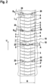
- FIG. 1 to 3 an embodiment of a pneumatic vehicle tire according to the invention is shown.
- a pneumatic vehicle tire has a tread which is provided with a profile.
- a section of the surface of the tread 1 of the pneumatic vehicle tire according to the invention is shown in its entire width.
- Various profile elements can be seen in the profile of the tread 1, a circumferential rib 3 is shown in the middle of the tread 1, a central circumferential rib.
- This circumferential rib 3 extends in the circumferential direction over the entire circumference of the pneumatic vehicle tire according to the invention and is delimited by two circumferential grooves 2, 2' running around the entire circumference of the pneumatic vehicle tire according to the invention.
- the two circumferential grooves 2, 2' run parallel to one another and perpendicular to the axial direction A of the pneumatic vehicle tire. Both circumferential grooves 2, 2' have the same cross-section perpendicular to the circumferential direction over the entire circumference of the tire. Both circumferential grooves 2, 2' have two sides that the two circumferential grooves 2, 2' in the axial direction A. Each of the two sides 4, 4' of the circumferential grooves 2, 2' limits the circumferential rib 3. A section of the circumferential rib 3 in the circumferential direction is also shown in the Figure 2 shown. In this figure, the circumferential grooves 2, 2' delimiting the circumferential rib 3 are also shown with their sides 4, 4', which delimit the circumferential rib 3.
- FIG. 3 the circumferential rib 3 is shown, this time in three-dimensional representation, whereby the circumferential rib 3 itself as in Figure 2 is developed in one plane.
- the view of the circumferential rib 3 in the axial direction A is shown, with a short section of the circumferential rib 3 in the circumferential direction U being shown.
- the circumferential grooves 2 and 2' can be seen, which delimit the circumferential rib 3.
- the side 4 of the circumferential groove 2 can be seen, which forms the edge of the circumferential rib 3.
- the sides 4, 4' of the circumferential grooves 2, 2' delimiting the circumferential rib 3 run in two parallel planes perpendicular to the axial direction A.
- the straight sides 4, 4' are thus perpendicular to the tread surface and extend along the circumferential direction.
- the distance between the sides 4, 4' in the axial direction A then specifies a constant width B of the circumferential rib 3 in the radial direction of the tire, which in the exemplary embodiment is 27 mm.
- the sides 4, 4' then merge with a curvature in the bottom area of the circumferential grooves 2, 2' into the groove base of the circumferential grooves 2, 2', as in Figure 3 shown.
- the circumferential rib is divided by fine incisions 6, which run from one to the other of the parallel sides (4, 4') of the two circumferential grooves (2, 2') over the entire width B of the circumferential rib 3.
- the fine incisions 6 have a regular distance d from each other in the circumferential direction U, which in the embodiment is 5.5 mm on the surface of the circumferential rib 3.
- Each fine incision 6 runs along a contour line 10.
- the shape of the contour line 10 is the same for all fine incisions 6 in the circumferential rib 3.
- the contour line 10 is formed by two straight lines, each of which forms an angle ⁇ of 15° with respect to the axial direction A and intersects in the middle of the circumferential rib 3.
- the two straight lines enclose an angle ⁇ of 150° with each other.
- a wavy line is superimposed on this contour line 10 along the course of the fine incisions 6, so that the fine incisions 6 have a wavy course in the middle of the circumferential rib 3.
- the tread depth of the circumferential grooves 2, 2' is 8 mm when the pneumatic vehicle tire is new
- the depth T F of the fine incisions 6 in the middle of the circumferential rib 3 is 7 mm. In the end region of the fine incisions 6, the depth T F of the fine incisions 6 is reduced.
- the depth T F is reduced by over 21% of the length L red of the contour line 10 at both end regions.
- the depth T F of the contour line is reduced over the length L red of 5.5 mm along the contour line 10.
- Every second fine incision 6 has a depth T F,1 of only 1.75 mm in its end region.
- the depth T F,2 of the other fine incisions is reduced in the end areas over the same length L red to 50 % of the profile depth T F and is therefore 3.5 mm.
- the fine incisions 6 are replaced at certain intervals in the circumferential direction U by a thin transverse groove 8.
- this distance is alternately four, five or six times the length of the distance d between the fine incisions 6 in an irregular sequence.
- the thin transverse grooves 8 are arranged at an irregular distance in order to avoid vibrations in the circumferential rib 3 due to resonances that can arise from a regular spacing of the thin transverse grooves 8.
- the width B Q of the thin transverse grooves 8 in the exemplary embodiment is three times as large as the width B F of the fine incisions 6.
- the width B F of the fine incisions 6 in the exemplary embodiment is 0.5 mm and correspondingly the width B Q of the thin transverse grooves 8 is 1.5 mm.
- the profile depth T Q of the thin transverse grooves is 8 mm.
- the transverse grooves 8 run along the same contour line 10 as the fine incisions 6.
- the fine incisions 8 run only along the contour line 10 and have no further component perpendicular to the contour line, as in the wave-shaped course of the fine incisions 6.
- the thin transverse grooves 8 each have a snow pocket 20 in their end areas.
- the end area of the contour line 10, which extends from a circumferential groove 2 to to the other circumferential groove 2', which delimits the circumferential rib 3 the area of the contour line 10, which begins at the circumferential grooves 2 and 2' and then extends inwards into the circumferential rib 3.
- the snow pockets 20 then have a length Ls along the contour line 10.
- the snow pockets 20 have the same length Ls as the length L red of the elevations of the fine incisions 6. Accordingly, the length Ls of the snow pockets is also 21% of the length of the contour line 10.
- the snow pockets 20 also have an extension parallel to the surface of the tread 1 perpendicular to the contour line 10.
- This width B S of the snow pockets 20 in the exemplary embodiment is twice as large as the width B Q of the thin transverse grooves 8 and is therefore 3 mm.
- the snow pockets 20 also have a depth T S in the radial direction.
- the depth T S of the snow pockets 20 in the example is exactly half the profile depth T Q of the thin transverse grooves 8. Accordingly, the profile depth T S of the snow pockets has a value of 4 mm.
- the Figure 3 further details of the design of the snow pockets 20 can be found.
- the snow pockets 20 At depth T S, the snow pockets 20 have a bottom region 21.
- this bottom region 21 is essentially parallel to the surface of the tread 1.
- the snow pockets 20 also have side surfaces 22.
- the side surfaces 22 run parallel to the contour line 10 and perpendicular to the surface of the tread 1, so that the surfaces have a component in the radial direction.
- a side surface 22 of the snow pockets is designed as an end surface 23, which is a surface perpendicular to the contour line 10. Between the bottom region 21 and the side surfaces 22, in particular the end surface 23, there is a transition with a radius of curvature of 1 mm.
- the bottom region 21 of the snow pockets 20 has a fine incision 25 in its center, which runs along the contour line 10 of the thin transverse grooves 8.
- the central circumferential rib 3 of the embodiment is characterized in that it has good snow-snow friction due to the snow pockets 20 provided, which is achieved by a rapid Filling the snow pockets 20 is available after a short time, and also by a uniform tilting of the provided profile block elements, whereby a good balance is achieved between snow behavior (snow performance) and ice behavior (ice performance) of the circumferential rib 3.
- the design of the snow pockets 20 further enables a very uniform elasticity or circumferential rigidity of the transverse rib 3 in the axial direction A.
- the snow pockets 20 provided on the edge of the circumferential rib 3 largely compensate for the elevations at the end of the fine incisions 6 of the circumferential rib 3.
- the structure of a central circumferential rib of the pneumatic vehicle tire according to the invention was explained in detail using the parameters described in this description. This structure must be adapted to the size of a pneumatic vehicle tire.
- the circumferential ribs 3 of the pneumatic vehicle tires according to the invention are used in pneumatic vehicle tires whose width is between 195 mm and 315 mm.
- the height of the tire can be between 35% of the width of the pneumatic vehicle tire and 65% of the width of the pneumatic vehicle tire.
- the rims on which such pneumatic vehicle tires are mounted can have a diameter of between 15 inches and 22 inches.
- a different number of fine sipes 6 and thin transverse grooves 8 can be provided over the circumference of the pneumatic vehicle tire.
- the number of fine sipes 6 and the transverse grooves 8 can grow with the circumference or only grow with the circumference to a certain extent. Such a proportion can be between 5 and 20%, for example.
- pneumatic vehicle tires according to the invention can of course also have other dimensions, as long as the advantageous properties of the described circumferential rib can be used in the pneumatic vehicle tire.
- the invention has been explained using many detailed embodiments. These are nevertheless examples of the invention. Accordingly, other embodiments of the pneumatic vehicle tire according to the invention can also have only individual features of an embodiment or simultaneously features of various described embodiments, unless explicitly stated otherwise.
Landscapes
- Engineering & Computer Science (AREA)
- Mechanical Engineering (AREA)
- Tires In General (AREA)
Description
- Die Erfindung betrifft einen Fahrzeugluftreifen mit einem ein Profil aufweisenden Laufstreifen. Das Profil des Laufstreifens weist zwei um den gesamten Reifen umlaufende Umfangsrillen auf. Durch zwei zueinander parallellaufende Seiten von diesen zwei Umfangsrillen, die senkrecht zur Achsrichtung A des Fahrzeugluftreifens verlaufen, wird eine mittige Umfangsrippe des Profils begrenzt. Diese Umfangsrippe weist in einem regelmäßigen Abstand in Umfangsrichtung Feinschnitte aufweist, die von einer zur anderen der zueinander parallellaufenden Seiten der zwei Umfangsrillen entlang einer Konturlinie verlaufen.
- Auch für den Einsatz im Winter geeignete Fahrzeugluftreifen, meist kurz Winterreifen genannt, müssen ein Fahrzeug auch dann stabil auf einer Fahrbahn halten, wenn diese verschneit oder vereist ist. Außerdem gehört zu dieser Winterperformance, die die Schnee- und Eisperformance umfasst, auch eine sichere Kurvenfahrt mit dem Fahrzeug, sowie ein sicheres Anfahren und Bremsen mit dem Fahrzeug.
- Um diese Eigenschaften zu erreichen, weist der Laufstreifen des Fahrzeugluftreifens ein entsprechend gestaltetes Profil auf.
- Zur Schneeperformance des Reifens tragen hauptsächlich drei Wirkmechanismen bei, die Gummi-Schneereibung, die Schnee-Schneereibung und die Kanten(scher)wirkung der Profilstruktur.
- Die Gummi-Schneereibung eines Fahrzeugluftreifens wird dabei bestimmt durch das Gummimaterial des Laufstreifens, insbesondere durch das Gummimaterial an der Oberfläche des Laufstreifens.
- Um die Schnee-Schneereibung zu erhöhen weist das Profil des Laufstreifens des Fahrzeugluftreifens Strukturen wie z.B. Nuten auf, die sich mit von der Fahrbahn aufgenommenem Schnee füllen. Bekannt ist hier aus der
WO 2018/103924 A1 , das Umfangsnuten sich mit einer Tiefe von 1,5 mm bis 2,5 mm und einer 2,0- bis 3,0-fachen Breite dieser Tiefe sich schnell und zuverlässig beim Fahren auf einer schneebedeckten Fahrbahn mit Schnee füllen. Ein schnelles Füllen einer Struktur im Profil des Fahrzeugluftreifens mit Schnee zur Erzeugung der Schnee-Schneereibung ist besonders wichtig, wenn ein Fahrzeug eine Anti-Schlupf-Regelung (ASR-System) oder ein AntiBlockiersystem (ABS) aufweist, da dann nach kurzen Schlupfwegen bzw. kurzen Eingriffszeiten das Profil des Fahrzeugluftreifens mit der Fahrbahn in Eingriff kommt und hierzu dann die Schnee-Schneereibung benötigt wird. - Die Kanten(scher)wirkung der Profilstruktur wird mit Feineinschnitten, auch als Lamellen bezeichnet, in regelmäßigen Abständen im Profil erreicht. Die Breite dieser Feineinschnitte ist geringer als die Breite von Rillen bzw. Nuten im Profil des Laufstreifens eines Fahrzeugluftreifens und beträgt zwischen 0,2 mm und 0,7 mm, bevorzugt zwischen 0,4 und 0,6 mm und besonders bevorzugt zwischen 0,45 mm und 0,55 mm. Die Feineinschnitte sind typischerweise in den Profilklötzen des Profils des Laufstreifens angeordnet, die durch Rillen im Profil gebildet werden. Durchläuft nun ein Profilklotz die Bodenaufstandsfläche des Fahrzeugluftreifens, d.h. der Profilklotz hat während der Reifenrotation Kontakt mit der Fahrbahn, so öffnen sich die Feineinschnitte im Profilklotz und es entstehen so Griffkanten, die die Kraftübertragung im Schnee erhöhen. Dabei verkippen die durch zwei Feineinschnitte bzw. einen Feineinschnitt und eine Profilklotzkante begrenzten Profilklotzelemente. Die Ausbildung der Griffkanten und der Verkippung der Profilklotzelemente nimmt mit der Tiefe der Feineinschnitte im Profil zu.
- Die Tiefe TF der Feineinschnitte kann jedoch an den Klotzrändern reduziert sein, z.B. um das Handling des Fahrzeugluftreifens zu erhöhen. Solche als Randanhebung der Feineinschnitte bezeichneten Strukturen der Feineinschnitte reduzieren anderseits die Ausbildung der Griffkanten und die Verkippung der Profilklotzelemente.
- Bei einer vereisten Fahrbahn ist das Verkippen der Profilklotzelements jedoch nachteilig, da sich hierdurch beim Durchlaufen der Bodenaufstandsfläche durch ein Profilklotz die Kontaktfläche zwischen den im Profilklotz vorhandenen Profilklotzelementen mit der vereisten Fahrbahn reduziert, so dass nur eine reduzierte Kontaktfläche zur Kraftübertragung zwischen Fahrzeugluftreifen und Fahrbahn beitragen kann.
- Diesem Zielkonflikt der Schnee -und Eisperformance bei Schnee- und Eiseingriff kann durch das Vorsehen von einem Bandprofil in einer Umfangsrippe des Profils des Fahrzeugluftreifenlaufstreifens Rechnung getragen werden. Hierbei läuft die Umfangsrippe einmal um den Reifenumfang und hat dabei eine feste Position in Achsrichtung A des Fahrzeugluftreifens. Die Achsrichtung A des Fahrzeugluftreifens ist dabei die Richtung der Achse, um die der auf eine Felge montierter Fahrzeugluftreifen in einem Fahrzeug rotiert. Entsprechend wird eine solche Umfangsrippe von zwei Umfangsrillen in Achsrichtung A begrenzt. Die Seite dieser Umfangsrillen, die die Umfangrippe begrenzen, laufen vorzugsweise dann zueinander parallel und verlaufen vorzugsweise in Umfangsrichtung senkrecht zur Achsrichtung A. Die die Umfangsrippe begrenzenden Seiten der Umfangsrillen, bzw. der Rand der Umfangsrippe weist dann keine Richtungskomponente in Achsrichtung auf. Dabei weist die Umfangsrippe als Bandprofil in einem regelmäßigen Abstand in Umfangsrichtung einen Feinschnitt auf. Da eine derartige Umfangsrippe keine Profilklötze aufweist, die durch Rillen, insbesondere Querrillen quer zur Umfangsrichtung, getrennt sind, ist ein Verkippen der durch die Feineinschnitte in der Umfangsrippe gebildeten Rippenelemente bei ihrem Durchlauf durch die Bodenaufstandsfläche reduziert. Anderseits stützen sich die Rippenelemente dabei sogar so gut ab, dass die Feineinschnitte sich nicht mehr so weit öffnen, dass die hierdurch entstehenden Griffkanten ihre volle Wirkung bei Schnee entwickeln. Auch die Schnee-Schneereibung ist bei einer derartigen Umfangsrippe nur gering ausgeprägt und beruht nur auf den sie begrenzenden Umfangsrillen mit voller Profiltiefe.
- Die Umfangsrippe ist in Achsrichtung A mittig und bevorzugt zentral positioniert. Eine Umfangsrippe ist dabei dann mittig, wenn es in Achsrichtung A zwischen der Umfangsrippe und der näher zu ihr liegenden Reifenschulter weitere Profilelemente wie z.B. Profilblöcke gibt. Eine Umfangsrippe ist eine zentrale Umfangsrippe, wenn sie zentral in Achsrichtung A im Laufstreifen des Fahrzeugluftreifens positioniert ist und damit die sie begrenzenden Seiten der zwei Umfangsrillen den gleichen Abstand zu der in Achsrichtung A näheren Reifenschulter aufweisen.
- Wenn in derartigen Umfangsrippen die Feineinschnitte des Bandprofils Randanhebungen am Rand der Umfangsrippe aufweisen, die in Umfangsrichtung hintereinander folgen, so führt dies zu einer erhöhten Umfangssteifigkeit der Umfangsrippe an ihren Rändern, die den Abrieb in diesem Bereich der Umfangsrippe erhöht.
- Aus der
EP 3 444 129 A1 sind mittige Umfangsrippen mit einer verbesserten Schnee-Schneereibung bekannt mit einem Bandprofil, beim dem sich gegenüber der Achsrichtung A angewinkelte gerade Feineinschnitte und Rillen in Umfangsrichtung abwechseln und die Rillen an ihren Enden zusätzlich eine Phase aufweisen. - Aus der
US 2020/0031171 A1 ist eine zentrale Umfangsrippe bekannt, die in regelmäßigem Abstand in Umfangsrichtung einen gegenüber der Achsrichtung A angewinkelte gerade Feinschnitt aufweist, und wobei anstelle eines Feineinschnitts in der achtfachen Länge des Abstands der Feinschnitte in Umfangsrichtung eine dünne genauso gegenüber der Achsrichtung A angewinkelte Querrille in der zentralen Umfangsrippe angeordnet ist. Diese Querrillen weisen in ihren Endbereichen eine Vertiefung auf, die größer ist als die Tiefe der Querrille und die gleiche Tiefe aufweist wie die Umfangsrillen, die die Umfangsrippe begrenzen. Die Seiten dieser Umfangsrillen, die die Umfangsrippe begrenzen weisen eine Zick-zack-Form bezüglich der Achsrichtung A auf und laufen nicht parallel zueinander. - Aus der
US 2018/0345734 A1 sind mittige Umfangsrippen eines Fahrzeugluftreifens mit guter Schnee- und Eisperformance bekannt, die in regelmäßigem Abstand in Umfangsrichtung einen gegenüber der Achsrichtung A angewinkelten geraden Feinschnitt aufweisen, und wobei anstelle eines Feineinschnitts in der fünffachen Länge des Abstands der Feinschnitte in Umfangsrichtung eine dünne genauso gegenüber der Achsrichtung A angewinkelte Querrille in der mittigen Umfangsrippe angeordnet ist. Diese Querrillen weisen in ihren Endbereichen eine Vertiefung auf, die größer ist als die Tiefe der Querrille in der Mitte der Umfangsrippe. - Aus der
EP 3 421 263 B1 sind mittige Umfangsrippen eines Fahrzeugluftreifens mit guter Schneeperformance bekannt, die in regelmäßigem Abstand in Umfangsrichtung einen gegenüber der Achsrichtung A angewinkelten geraden Feinschnitt aufweisen, wobei bei jedem zweiten Feineinschnitt ein Teil durch eine Querrille ersetzt wird, die tiefer als die Feineinschnitte ist. - Aus der
US 2018/0290498 A1 sind Umfangsrippen im Schulterbereich eines Fahrzeugluftreifens bekannt, die in regelmäßigem Abstand in Umfangsrichtung einen Feinschnitt aufweisen, wobei bei jedem fünften Feineinschnitt in Umfangsrichtung die Endbereiche einen Rillenabschnitt aufweisen, der ein größere Breite aufweist als der Feineinschnitt und eine größere Tiefe als der Feineinschnitt. Die Rillenabschnitte sind dazu vorgesehen, sich beim Fahren auf einer schneebedeckten Fahrbahn mit Schnee zu füllen. - Ein weiterer gattungsbildender Fahrzeugluftreifen ist aus der
EP 1 961 586 A1 bekannt. - Trotz der schon bekannten Profilstrukturen stellt sich weiterhin die Aufgabe, den Konflikt von Schnee- und Eisperformance noch besser zu lösen unter Berücksichtigung eines reduzierten Reifenverschleißes durch Abrieb.
- Gelöst wird die Aufgabe durch einen Fahrzeugluftreifen gemäß Patentanspruch 1.
- Ein derartiger Fahrzeugluftreifen weist einen Laufstreifen mit einem Profil auf, der eine mittige Umfangsrippe aufweist, die durch zwei mindestens nahezu zueinander parallel laufende Seiten von zwei um den gesamten Fahrzeugluftreifen umlaufende Umfangsrillen begrenzt wird, die mindestens nahezu senkrecht zur Achsrichtung A des Fahrzeugluftreifens verlaufen, indem sie lediglich von der radialer Richtung einer senkrechten Ebene zur Achsrichtung A um einen Winkel y, der kleiner als 15 ° ist, so abweichen, dass hierdurch die Breite der Umfangsrippe mit zunehmender Profiltiefe konstant bleibt oder zunimmt, wobei die Umfangsrippe in einen regelmäßigem Abstand d in Umfangsrichtung einen Feinschnitt aufweist, der von einer zur anderen der zueinander parallel laufende Seiten der zwei umlaufenden Umfangsrillen entlang einer Konturlinie verläuft, und wobei anstelle eines Feineinschnitts in der drei- bis siebenfachen Länge des Abstands d der Feinschnitte in Umfangsrichtung jeweils eine dünne Querrille in der mittigen Umfangsrippe angeordnet ist, deren Breite BQ mindestens 2,5 mal so groß ist wie die Breite BF eines Feineinschnitts und die die Konturlinie der Feineinschnitte aufweist, und wobei die Tiefe TF der Feineinschnitte mindestens teilweise über eine Länge Lred der Konturlinie in den Endbereichen der Feineinschnitte reduziert ist und über 80 % bis 250 % dieser Länge Lred der Konturlinie die dünnen Querrillen in ihren Endbereichen eine Schneetasche aufweisen, die eine Breite BS senkrecht zur Konturlinie aufweist, die mindestens 1,5 mal so groß ist wie die Breite Bq der dünnen Querrille, und eine Tiefe TS , die maximal 65 % der Profiltiefe TQ der dünnen Querrille beträgt.
- Ein erfindungsgemäßer Fahrzeugluftreifen weist also einen Laufstreifen mit einem Profil auf, dass zwei um den gesamten Reifen umlaufende Umfangsrillen aufweist. Bei den beiden Umfangsrillen handelt es sich um benachbarte Umfangsrillen, zwischen denen sich im Laufstreifen eine mittige Umfangsrippe befindet.
- Jede Umfangsrille eines Fahrzeugluftreifens hat nun in Achsrichtung A des Fahrzeugluftreifens zwei Seiten, wenn man ihren Querschnitt senkrecht zur Umfangsrichtung betrachtet. Die beiden Seiten befinden sich bezogen auf den tiefsten Punkt des Querschnitts der Umfangsrille, dessen Abstand zu der Oberfläche des Laufstreifens der Profiltiefe der Fahrzeugluftreifens entspricht, in Achsrichtung A auf der einen oder anderen Seite des tiefsten Punkts des Querschnitts. Beide Seiten der Umfangsrille begrenzen dabei eine Umfangsrippe aus dem Gummimaterial des Laufstreifens. Die aufeinander zugewandten Seiten zweier benachbarter umlaufender Umfangsrillen begrenzen dann gemeinsam eine Umfangsrippe des Profils des Laufstreifens.
- Bei einem erfindungsgemäßen Fahrzeugluftreifen laufen die die Umfangsrippe begrenzenden Seiten der beiden Umfangsrillen mindestens nahezu parallel zueinander und mindestens nahezu senkrecht zur Achsrichtung A des Fahrzeugluftreifens. Hierbei weichen die die Umfangsrippe begrenzenden Seiten lediglich von der radialer Richtung einer senkrechten Ebene zur Achsrichtung A um einen Winkel γ ab, der kleiner als 15 ° ist. Diese Abweichung der die Umfangsrippe begrenzenden Seiten ist derart, dass die Breite der Umfangsrippe mit zunehmender Profiltiefe konstant bleibt oder zunimmt. Damit verlaufen beide die Umfangsrippe begrenzenden Seiten parallel zur Umfangsrichtung des Fahrzeugluftreifens und besitzen nur die durch den Winkel γ gegebene geringe Abweichung von der radialen Richtung des Fahrzeugluftreifens. Die radiale Richtung des Fahrzeugluftreifens steht senkrecht auf seiner Achsrichtung A, um die er rotiert. Entlang der radialen Richtung nach innen, d.h. in Richtung auf die Mitte des Fahrzeugluftreifens, nimmt die Profiltiefe des Reifenprofils zu. Die die Umfangsrippe begrenzenden Seiten weichen nun so um den Winkel γ von der radialen Richtung des Fahrzeugluftreifens ab, dass die Breite der Umfangsrippe mit zunehmender Profiltiefe, also nach innen, konstant bleibt oder zunimmt. Entsprechend hat die Umfangsrippe dann über den gesamten Umfang des erfindungsgemäßen Fahrzeugluftreifens an der Oberfläche und bei jeder Profiltiefe eine konstante Breite B in Achsrichtung A, die durch den Abstand der mindestens nahezu parallelen Seiten in Achsrichtung gegeben ist, die aber gemäß dem Winkel y, der mit der Profiltiefe variiert, nach innen zunehmen kann. In einer bevorzugten Ausführungsform liegen die beiden die Umfangrippe begrenzenden Seiten der beiden parallellaufenden Umfangsrillen in zwei parallelen Ebenen , die senkrecht zur Achsrichtung A sind. Dann ist der Winkel γ abgesehen vom Bodenbereich der Umfangsrillen über die Profiltiefe 0 und die Breite B über die Profiltiefe des Profils konstant. In einer besonders bevorzugten Ausführungsform verlaufen auch die beiden Umfangsrillen selber, die die Umfangrippe begrenzen, parallel zueinander in zwei Ebenen senkrecht zur Achsrichtung A, d.h. der tiefsten Punkt des Querschnitts der Umfangsrillen senkrecht zur Umfangsrichtung befindet sich über den gesamten Reifenumfang in jeweils einer der beiden Ebenen senkrecht zur Achsrichtung A. Besonders bevorzugt wiesen dabei beide Umfangsrillen über dem gesamten Reifenumfang die gleiche Breite in Achsrichtung A auf. Reine Fertigungstoleranzen bei der Herstellung des Reifenprofils werden hierbei bzgl. der Ausgestaltung der Umfangsrillen nicht berücksichtigt.
- Typischerweise beträgt die Breite B in Achsrichtung Ader Umfangsrippe an ihrer Oberfläche im Neuzustand des Fahrzeugluftreifens 17 mm bis 40 mm, bevorzugt 20 mm bis 30 mm und besonders bevorzugt 22 mm bis 28 mm.
- Die Umfangsrippe weist dabei in einen regelmäßigem Abstand d in Umfangsrichtung einen Feinschnitt auf. Dabei verlaufen die in der Umfangsrippe vorhandenen Feineinschnitte von einer zur anderen der zueinander parallellaufenden, die Umfangsrippe begrenzenden Seiten der zwei umlaufenden Umfangsrillen entlang einer Konturlinie. Damit verlaufen die Feineinschnitte von einem Ende der Umfangsrippe in Achsrichtung A, dass durch eine Seite einer der beiden umlaufenden Umfangsrillen gebildet wird zum anderen Ende der Umfangsrippe in Achsrichtung A, dass durch eine Seite der zweiten der beiden umlaufenden Umfangsrillen gebildet wird. Alle Feineinschnitte verlaufen dabei entlang einer festgelegten Konturlinie, die ebenfalls von einem Ende der Umfangsrippe in Achsrichtung A zum anderen Ende der Umfangsrippe in Achsrichtung A verläuft. Die Konturlinie definiert den Verlauf der Feineinschnitte an der Oberfläche des Laufstreifens unabhängig von der Umfangsposition des Feineinschnitts. Dabei handelt es sich bei der Konturlinie lediglich um die Hauptlinie, entlang der die Feineinschnitte von einem Ende der Umfangsrippe zum anderen Ende der Umfangsrippe verlaufen. Der eigentliche Verlauf des Feineinschnitts an der Oberfläche des Laufstreifens kann von dieser Hauptlinie abweichen, da hierbei noch ein Verlauf des Feineinschnitts zur Hauptlinie ergänzt sein kann, der im Wesentlichen in der Oberfläche des Laufstreifens eine Komponente senkrecht zur Hauptlinie aufweist, d.h. der in der Oberfläche des Laufstreifens hauptsächlich senkrecht zur Konturlinie verläuft. Dabei ist die Dimension der Abweichung von der Hauptlinie deutlich kleiner als die Breite B der Umfangsrippe in Achsrichtung A. Typischerweise ist die Dimension der Abweichung maximal 15 % der Breite B der Umfangsrippe, vorzugsweise maximal 5 % der Breite B der Umfangsrippe und besonders bevorzugt 3 % der Breite B der Umfangsrippe. Der derart ergänzte Verlauf hat seine Hauptkomponente, d.h. seine Hauptverlaufsrichtung, in einer Richtung, die typischer nicht mehr als 20 ° von der Senkrechten zur Konturlinie in der Oberfläche des Laufstreifens abweicht, bevorzugt nicht mehr als 5 ° von der Senkrechten zur Konturlinie in der Oberfläche des Laufstreifens abweicht und besonders bevorzugt nicht mehr als 2 ° von der Senkrechten zur Konturlinie in der Oberfläche des Laufstreifens abweicht. Typischerweise oszilliert oder mäandriert der ergänzte Verlauf in der Richtung der Hauptkomponente um die Konturlinie oder weist in dieser Richtung einen Zickzack-Verlauf oder andern periodischen Verlauf auf, wobei die Periode entlang der Konturlinie variieren kann. Der ergänzte Verlauf liegt vorzugsweise nur über einen Teil der Konturlinie vor. Die Feineinschnitte erstrecken sich von der Oberfläche der Umfangsrippe in radialer Richtung des Fahrzeugluftreifens in eine Tiefe TF, wobei sie ihrem Verlauf an der Oberfläche des Laufstreifens folgen. In Umfangsrichtung benachbarte Feineinschnitte weisen dabei in Umfangsrichtung nahezu den gleichen Abstand dn auf und laufen dabei bevorzugt parallel zueinander. Der Abstand dn benachbarter Feineinschnitte in Umfangsrichtung variiert dabei über den gesamten Reifenumfang typischerweise um maximal 10 % des mittleren Abstands d, vorzugsweise um maximal 5 % des mittleren Abstands d und besonders bevorzugt um maximal 2 % des mittleren Abstands d. Dies beruht insbesondere nur auf Fertigungstoleranzen im Rahmen der Herstellung des Fahrzeugluftreifens. Typischerweise beträgt der regelmäßigem Abstand d in Umfangsrichtung der Feinschnitte an der Oberfläche der Umfangsrippe im Neuzustand des Fahrzeugluftreifens 3 mm bis 9 mm, bevorzugt 4 mm bis 7 mm und besonders bevorzugt 5 mm bis 6 mm.
- Anstelle dieser Feineinschnitte ist in der Umfangsrippe der erfindungsgemäßen Fahrzeugluftreifen in der drei- bis siebenfachen Länge des Abstands d der Feinschnitte in Umfangsrichtung jeweils eine dünne Querrille angeordnet. Diese dünnen Querrillen können jeweils im gleichen Abstand oder bevorzugt in unterschiedlichen Abständen in Umfangsrichtung in der Umfangsrille angeordnet sein, wobei der Abstand der dünnen Querrillen im Umfangrichtung jeweils ein Vielfaches des Abstands d der Feineinschnitte in Umfangsrichtung ist. Mit einer Anordnung der dünnen Querrillen mit unterschiedlichen Abständen in Umfangsrichtung wird ein besseres akustisches Verhalten des erfindungsgemäßen Fahrzeugluftreifens erreicht, da hierdurch Schwingungen aufgrund einer bestimmten Resonanzperiode in Umfangsrichtung aufgrund der dünnen Querrippen in der Umfangsrippe vermieden werden.
- Die Breite BQ der dünnen Querrille in der mittigen Umfangsrippe des erfindungsgemäßen Fahrzeugluftreifens ist mindestens 2,5 mal so groß ist wie die Breite BF eines Feineinschnitts in der mittigen Umfangsrippe, bevorzugt 2,5 bis 5 mal so groß ist wie die Breite BF eines Feineinschnitts, besonders bevorzugt 2,75 bis 4,5 mal so groß ist wie die Breite BF eines Feineinschnitts und äußerst bevorzugt 2,8 bis 4 mal so groß ist wie die Breite BF eines Feineinschnitts. Die Breite BQ der dünnen Querrillen und die Breite BF der Feineinschnitte ist die Breite senkrecht zu der gemeinsamen Konturlinie der dünnen Querrillen und Feineinschnitte.
- Die dünnen Querrillen in der mittigen Umfangsrippe des erfindungsgemäßen Fahrzeugluftreifens weisen nämlich die Konturlinie der Feineinschnitte auf. Hierdurch weisen die Querrillen und Feineinschnitte der mittigen Umfangsrippe im Wesentlichen die gleiche Form an der Oberfläche des Laufstreifens eines erfindungsgemäßen Fahrzeugreifens auf. Damit folgen die dünnen Querrillen der gleichen Konturlinie wie die Feineinschnitte. Hierbei verlaufen die Konturlinie einer dünnen Querrille und eines benachbarten Feineinschnitte um den Abstand d in Umfangsrichtung versetzt parallel zueinander. Wesentlich ist, dass jede dünne Querrille entlang der Konturlinie verläuft und nicht, wie ein Feineinschnitt noch einen ergänzten Verlauf aufweisen kann, der im Wesentlichen eine Komponente senkrecht zur Konturlinie aufweist. Die dünnen Querrillen erstrecken sich von der Oberfläche der Umfangsrippe in radialer Richtung des Fahrzeugluftreifens in eine Tiefe TQ, wobei sie ihrem Verlauf an der Oberfläche des Laufstreifens folgen.
- Die Tiefe TF der Feineinschnitte der mittigen Umfangsrippe des erfindungsgemäßen Fahrzeugluftreifens ist mindestens teilweise über eine Länge Lred der Konturlinie in den Endbereichen der Feineinschnitte reduziert. Damit ist die Tiefe TF eines derartigen Feineinschnitts in einem Endbereich oder beiden Endbereichen des Feineinschnitts, die benachbart zu den beiden die Umfangsrippe begrenzenden Umfangrillen sind, auf eine reduzierte Tiefe TF,1 begrenzt. Ein solcher Feineinschnitt weist dann eine Randanhebung oder zwei Randanhebungen auf. Es können sowohl nur ein Teil der Feineinschnitte der mittigen Umfangrippe eine oder zwei derartige Randanhebungen aufweisen als auch alle Feineinschnitte. Die Reduzierung der Tiefe TF kann bei allen Feineinschnitten mit Randanhebung gleich oder auch unterschiedlich sein. Die Länge Lred der Konturlinie, in der eine Randanhebung vorliegt, beginnt jeweils an einem Ende der Oberfläche der Umfangsrippe in Achsrichtung A, also an einer der beiden Seiten einer der beiden Umfangrillen, die die Umfangsrippe begrenzen, und endet dann an einem bestimmten Punkt der Konturlinie.
- Über nahezu die gleiche oder eine größere Länge LS, nämlich über 80 % bis 250 % dieser Länge Lred der Konturlinie weisen die dünnen Querrillen der Umfangsrippe in ihren Endbereichen eine Schneetasche auf. Damit erstreckt sich eine solche Schneetasche an den Enden der dünnen Querrille über diese Länge LS entlang der Konturlinie ebenfalls beginnend an einer der beiden Seiten einer der beiden Umfangrillen, die die Umfangsrippe begrenzen. Die Aufgabe einer solchen Schneetasche, die eine Kavität im Reifenprofil darstellt, ist es, sich schnell mit Schnee von der Fahrbahn im Fahrbetrieb zu füllen, so dass entsprechend schnell ein erhöhter Schneegriff durch die Schnee-Schnee-Reibung eintritt.
- Die Schneetaschen an den Enden der dünnen Querrillen weisen hierbei eine Breite BS senkrecht zur Konturlinie der dünnen Querrillen auf, die parallel zur Reifenoberfläche bestimmt wird, in der die Konturlinie verläuft, die mindestens 1,5 mal so groß ist wie die Breite BQ der dünnen Querrille, und eine Tiefe TS , die maximal 65 % der Profiltiefe TQ der dünnen Querrille beträgt. Damit sind die weiteren geometrischen Dimensionen der in der mittigen Umfangsrippe eines erfindungsgemäßen Fahrzeugluftreifens vorgesehenen Schneetaschen gekoppelt an die Dimensionen der dünnen Querrillen in der Umfangsrippe. Sie sind breiter als die dünnen Querrillen senkrecht zur Konturlinie der dünnen Querrillen, die ja auch die Konturlinie der Feineinschnitte ist, und zwar mindestens 1,5 mal so breit wie die dünnen Querrillen. Ihre Tiefe Ts dagegen ist geringerer als die Profiltiefe TQ der dünnen Querrille, und zwar derart, dass ihre Tiefe TS maximal 65 % der Profiltiefe TQ der dünnen Querrille beträgt. Hierbei gibt die Tiefe TS der Schneetaschen und die Profiltiefe TQ der dünnen Querrillen jeweils die Ausdehnung der Schneetaschen bzw. dünnen Querrillen in radialer Richtung des Fahrzeugluftreifens ausgehend von der Oberfläche des Laufstreifens de Fahrzeugluftreifens an. Hierbei weist die radiale Richtung von der Reifenoberfläche nach innen auf die Drehachse des Fahrzeugluftreifens und steht senkrecht auf dieser. Damit sind in einer mittigen Umfangsrippe eines erfindungsgemäßen Fahrzeugluftreifens an den Enden von dünnen Querrillen, die von einer Seite der Umfangsrippe zur anderen verlaufen, Schneetaschen vorgesehen, die lateral, d.h. parallel zur Reifenoberfläche eine Ausdehnung aufweisen, die gegeben ist durch eine Länge Ls entlang der Konturlinie der zugehörigen dünnen Querrille und eine Breite Bs senkrecht zur der Konturlinie. Die Breite BS ist dabei bewusst gegenüber der Breite BQ der dünnen Querrille erhöht und die Länge LS ist in ähnlicher Dimension oder einem bestimmten Maß größer gewählt wie die Länge Lred der Randanhebungen der Feineinschnitte der Umfangsrippe. Insgesamt weisen die Schneetaschen so eine große Querschnittsfläche an der Riefenoberfläche auf, die im Fahrbetrieb bei einer verschneiten Fahrbahn sich mit Schnee füllen kann. Weiter bedingt die begrenzte Tiefe Ts der Schneetaschen ein schnelles Füllen der Schneetasche mit Schnee, so dass schnell erhöhter Schneegriff durch die Schnee-Schnee-Reibung ermöglicht wird. Ein solcher Eingriff ist besonders vorteilhaft, wenn ein Fahrzeug eines Anti-Schlupf-Regelung (ASR) oder ein Antiblocksystem (ABS) aufweist und damit in der Lage ist, die verbesserte Reibung schnell zu nutzen.
- Weiter weist Länge Ls der Schneetaschen, die über 80 % bis 250 % der Länge Lred der Randanhebungen der Feinschnitte entlang der Konturlinie beträgt, nahezu die gleiche Dimension wie die Länge Lred der Randanhebungen auf oder ist größer wie die Länge Lred der Randanhebungen. Damit sind die Schneetaschen gezielt in axialer Richtung auch in der gleichen Position wie die Randanhebungen der Feineinschnitte positioniert, da so die Schneetaschen als Kavitäten einer Versteifung der Umfangsrippe in dieser axialen Position, d.h. an ihren Enden in Achsrichtung A, durch die Randanhebungen entgegen wirken und so die Umfangssteifigkeit, also die Elastizität der Umfangsrippe, in axialer Richtung A vergleichmäßigt wird. Dies begünstigt einen gleichmäßigeren Abrieb des Laufstreifens eines erfindungsgemäßen Fahrzeugluftreifens. Diese Vergleichmäßigung basiert auf allen Dimensionen der Schneetaschen, d.h. neben ihrer Länge LS auch ihrer Breite BS und ihrer Tiefe TS.
- Durch das beschriebene Vorsehen genau definierter Schneetaschen in der Profilstruktur einer mittigen Umfangsrippe mit gleichmäßigen Feinschnitten, die teilweise durch dünne Querrillen ersetzt werden, kann also sowohl die Schnee-Schnee-Reibung eines Fahrzeugluftreifens verbessert werden als auch gleichzeitig das Abriebverhalten des Fahrzeugluftreifens.
- In einer bevorzugten Ausführungsform ist die mittige Umfangsrippe des erfindungsgemäßen Fahrzeugluftreifens seine zentrale Umfangsrippe. In dieser Position hat die Umfangsrippe mindestens zumeist beim Fahrbetrieb den direkten Kontakt mit der Fahrbahn, so dass die Schneetaschen der Umfangsrichtung dann am sichersten bei einer verschneiten Fahrbahn schnell mit Schnee gefüllt werden und sich entsprechend schnell die Schnee-Schnee-Reibung aufbaut.
- In einer anderen Ausführungsform sind die dünnen Querrillen anstelle eines Feineinschnitts über verschiedene Vielfache des Abstands d der Feinschnitte in Umfangsrichtung in der mittigen Umfangsrille des erfindungsgemäßen Fahrzeugluftreifens in der Umfangsrichtung angeordnet. Durch dieses Anordnen der dünnen Querrillen in verschiedenen Abständen über den Reifenumfang, wobei trotzdem die Folge der verschiedenen Vielfache sich über den Reifenumfang periodisch wiederholen kann, wird wie bereits zuvor angesprochen, das akustisches Verhalten des erfindungsgemäßen Fahrzeugluftreifens verbessert. Die Folge der Vielfache kann zum Beispiel aus genau zwei verschiedenen Vielfachen, z.B. den Vierfachen und Fünffachen bestehen, die sich unregelmäßig oder regelmäßig wiederholen. In diesem Beispiel wird dann jeder vierter oder fünfte Feineinschnitt durch ein dünne Querrille ersetzt, die an ihren Enden eine Schneetasche mit den zuvor beschriebenen Abmessungen aufweist.
- In einer bevorzugten Ausführungsform ist anstelle eines Feineinschnitts in der vier- bis sechsfachen Länge des Abstands d der Feinschnitte in Umfangsrichtung, besonders bevorzugt in der vier- bis fünffachen Länge des Abstands d der Feinschnitte in Umfangsrichtung in der mittigen Umfangsrippe eines erfindungsgemäßen Fahrzeugluftreifens jeweils die zuvor beschriebene dünne Querrille mit ihren Schneetaschen angeordnet. Insbesondere bei diesen Abständen der dünnen Querrillen wird ein Verkippen der Profilklotzelemente in angemessener Form erreicht, um sowohl eine vorteilhafte Schnee- als auch Eisperformance aufgrund der Umfangsrippe zu erreichen.
- Bevorzugt ist bei der mittigen Umfangsrippe eines erfindungsgemäßen Fahrzeugluftreifens die Breite BQ der dünnen Querrillen maximal 5 mal so groß ist wie die Breite BF eines Feineinschnitts. Auch dies unterstützt das Verkippen der Profilklotzelemente in angemessener Form und vermeidet ein zu großes Verkippen einzelner Profilklotzelemente.
- Bevorzugt sind die Schneetaschen der dünnen Querrillen der mittigen Umfangsrippe eines erfindungsgemäßen Fahrzeugluftreifens symmetrisch zur Konturlinie der dünnen Querrillen angeordnet. Dies trägt zum gleichmäßigen Verkippen der zur dünnen Querrille benachbarten Profilklotzelemente bei.
- Bevorzugt weisen die Schneetaschen der dünnen Querrillen der mittigen Umfangsrippe eines erfindungsgemäßen Fahrzeugluftreifens eine Breite BS senkrecht zur Konturlinie aufweisen, die 2 bis 3 mal so groß ist wie die Breite BQ der dünnen Querrille. Besonders bevorzugt ist Breite BS der Schneetaschen 2,2 bis 2,5 mal so groß ist wie die Breite BQ der dünnen Querrille. Dies trägt zu einer guten Schnee-Schneereibung bei gleichzeitiger angemessener Verkippung der Profilklotzelemente und gleichmäßiger Elastizität in Achsrichtung A der mittleren Umfangsrippe bei.
- Bevorzugt weisen die Schneetaschen der dünnen Querrillen der mittigen Umfangsrippe eines erfindungsgemäßen Fahrzeugluftreifens eine Tiefe Ts auf, die 35 bis 60 % der Profiltiefe TQ der dünnen Querrille beträgt, besonders bevorzugt 40 % bis 58 % der Profiltiefe TQ der dünnen Querrille beträgt und ganz besonders bevorzugt 50 % bis 55 % der Profiltiefe der dünnen Querrille beträgt. Auch dies trägt zu einer guten Schnee-Schneereibung nach kurzer Zeit bei gleichzeitiger angemessener Verkippung der Profilklotzelemente und gleichmäßiger Elastizität und damit gleichmäßigem Reifenabrieb in Achsrichtung A der mittleren Umfangsrippe bei.
- Bevorzugt wiesen die dünnen Querrillen der mittigen Umfangsrippe eines erfindungsgemäßen Fahrzeugluftreifens in ihren Endbereichen über 95 % bis 200 % der Länge Lred der Konturlinie, über die die Tiefe TF der Feineinschnitte in den Endbereichen der Feineinschnitte reduziert ist, eine Schneetasche der Länge Ls auf und besonders bevorzugt wiesen diese dünnen Querrillen über 105 % bis 130 % der Länge Lred der Konturlinie, über die die Tiefe der Feineinschnitte in den Endbereichen der Feineinschnitte reduziert ist, eine Schneetasche der Länge Ls auf. Insbesondere die Überstimmung zwischen der Position der Anhebungen der Feineinschnitte mit der Position der Schneetaschen trägt dazu bei, dass die Elastizität in Achsrichtung A der mittleren Umfangsrippe in Achsrichtung A recht gleichmäßig ist. Insbesondere auch an den Seiten der Umfangsrippe liegt dann trotz der Anhebungen der Feineinschnitte nahezu die gleiche Umfangssteifigkeit von wie in der Mitte der Umfangsrippe. Hierdurch wird auch der Abrieb des Gummimaterials der Umfangsrippe über die gesamte Breite der Umfangsrippe in Achsrichtung mindestens nahezu gleichmäßig.
- Vorzugsweise weisen die dünnen Querrillen der mittigen Umfangsrippe eines erfindungsgemäßen Fahrzeugluftreifens in ihren Endbereichen über eine Länge Ls der Konturlinie von 2,5 mm bis 8 mm eine Schneetasche auf, besonders bevorzugt über eine Länge Ls der Konturlinie von 3,5 mm bis 7 mm und ganz besonders bevorzugt über eine Länge der Konturlinie von 4 mm bis 5,5 mm. Hierbei werden sowohl eine gute Schnee-Schneereibung als auch eine recht gleichmäßige Elastizität in Achsrichtung A der mittleren Umfangsrippe erreicht.
- Die Schneetaschen der dünnen Querrillen der mittigen Umfangsrippe eines erfindungsgemäßen Fahrzeugluftreifens weisen einen Bodenbereich und Seitenflächen auf. Der Bodenbereich begrenzt die Schneetaschen in radialer Richtung in einer Tiefe Ts. Hierbei kann die Tiefe TS jedoch in Achsrichtung und Umfangsrichtung um bis 20 % variieren, bevorzugt um bis 5 % und besonders bevorzugt um bis zu 1 %. Die Seitenflächen begrenzen die Schneetaschen durch Flächen, die sich von der Bodenfläche bis zur Oberfläche des Fahrzeugluftreifens erstrecken. Insbesondere kann eine Seitenfläche dabei parallel zur Konturlinie verlaufen oder als Endfläche der Schneetasche senkrecht zur Konturlinie sein. Bevorzugt geht die Fläche des Bodenbereichs der Schneetaschen mit einem Krümmungsradius von 0,2 mm bis 1,5 mm in die Seitenflächen übergeht, besonders bevorzugt mit einem Krümmungsradius von 0,5 mm bis 1,25 mm und ganz besonders bevorzugt mit einem Krümmungsradius von 0,8 mm bis 1,1 mm. Hierdurch wird die schnelle Befüllung der Schneetaschen mit Schnee während des Fahrbetriebs auf Schnee weiter verbessert, was entsprechend schneller zu einer guten Schnee-Schnee-Reibung führt.
- In einer Ausführungsform weisen die Schneetaschen der dünnen Querrillen der mittigen Umfangsrippe eines erfindungsgemäßen Fahrzeugluftreifens einen Bodenbereich und eine Endfläche als Seitenfläche auf. Typischerweise geht die Fläche des Bodenbereichs mit einem Krümmungsradius von 0,2 mm bis 1,5 mm in die Endfläche über, bevorzugt mit einem Krümmungsradius von 0,5 mm bis 1,25 mm und besonders bevorzugt mit einem Krümmungsradius von 0,8 mm bis 1,1 mm. Hierdurch wird die schnelle Befüllung der Schneetaschen mit Schnee während des Fahrbetriebs auf Schnee weiter verbessert, was entsprechend schneller zu einer guten Schnee-Schnee-Reibung führt.
- Typischerweise weisen die Schneetaschen der dünnen Querrillen der mittigen Umfangsrippe eines erfindungsgemäßen Fahrzeugluftreifens einen Bodenbereich auf, der sich in radialer Richtung nach innen, d.h. in Richtung auf die Mitte des Fahrzeugluftreifens, mit einem Feinschnitt entlang der Konturlinie fortsetzt. Dies fördert die Verkippung der Profilklotzelemente in der Umfangsrippe, insbesondere die Verkippung der zur jeweiligen Querrille benachbarten Profilklotzelemente, die so durch die gegenüber der Profiltiefe TQ der dünnen Querrippen verringerte Tiefe TS der Schneetaschen nicht verringert wird.
- Typischerweise weisen hierbei die Feinschnitte im Bodenbereich der Schneetaschen die gleiche Breite BF auf wie die Feineinschnitte der Umfangsrippe, die nicht durch eine dünne Querrille ersetzt wurden. Dies fördert eine über den Umfang gleichmäßige Verkippung der Profilklotzelemente und die Gleichmäßigkeit der Elastizität der Umfangsrippe in Achsrichtung A weiter.
- Bevorzugt weisen die Feinschnitte im Bodenbereich der Schneetaschen die gleiche Tiefe TF auf wie die Feineinschnitte der Umfangsrippe, die nicht durch eine dünne Querrille ersetzt wurden, in der Mitte der Umfangsrippe. Auch dies fördert eine über den Umfang gleichmäßige Verkippung der Profilklotzelemente und die Gleichmäßigkeit der Elastizität der Umfangsrippe in Achsrichtung weiter.
- In einer Ausführungsform ist die Konturlinie der Feineinschnitte der mittigen Umfangsrippe eines erfindungsgemäßen Fahrzeugluftreifens eine Gerade, die vorzugsweise senkrecht zu den parallellaufenden Seiten der zwei umlaufenden Umfangsrillen ist.
- In einer Ausführungsform ist die Konturlinie der Feineinschnitte der mittigen Umfangsrippe eines erfindungsgemäßen Fahrzeugluftreifens in der Mitte der Umfangsrippe leicht angewinkelt. So kann die Konturlinie hierbei durch zwei zueinander angewinkelte Geraden gebildet werden, die miteinander einen Winkel β von 140 ° bis 170 ° einschließen, bevorzugt einen Winkel β von 150 ° bis 165°.
- In bestimmten Ausführungsformen eines erfindungsgemäßen Fahrzeugluftreifens weicht die Konturlinie der Feineinschnitte im Endbereich der Feineinschnitte von der Achsrichtung A des Fahrzeugluftreifens um einem Winkel α von weniger als 20°, bevorzugt weniger als 15° und besonders bevorzugt weniger als 8° ab.
- In bestimmten Ausführungsformen eines erfindungsgemäßen Fahrzeugluftreifens sind die der Konturlinie entlanglaufenden Feineinschnitte der mittleren Umfangsrippe über einen Teil der Konturlinie wellenförmig ausgeprägt. In diesem Teil der Konturlinie weicht der eigentliche Verlauf des Feineinschnitts von der Hauptlinie der Konturlinie ab. Der Verlauf des Feineinschnitts wird um eine wellenförmige Komponente senkrecht zur Konturlinie ergänzt. Statt der wellenförmigen Komponente kann der Verlauf des Feineinschnitts auch um eine Zick-Zack-Linie und eine andere oszillierende Komponente ergänzt sein.
- In bestimmten Ausführungsformen ist die Tiefe TF der Feineinschnitte teilweise jeweils über eine Länge Lred der Konturlinie von 7 % bis 35 % in einem Endbereich oder bevorzugt beiden Endbereichen der Feineinschnitte reduziert, bevorzugt über jeweils eine Länge Lred der Konturlinie von 12 % bis 30 % und besonders bevorzugt über eine Länge Lred der Konturlinie von 16 % bis 23 %. Bevorzugt ist die Tiefe TF aller Feineinschnitte über eine derartige Länge Lred der Konturlinie in beiden Endbereichen der Feineinschnitte reduziert.
- In bestimmten anderen Ausführungsformen ist die Tiefe TF der Feineinschnitte teilweise jeweils über eine Länge Lred der Konturlinie von 1,5 mm bis 9 mm einem Endbereich oder bevorzugt in beiden Endbereichen der Feineinschnitte reduziert, bevorzugt jeweils über eine Länge Lred der Konturlinie von 2,5 mm bis 7,5 mm und besonders jeweils über eine Länge Lred der Konturlinie von 3,5 mm bis 5,5 mm. Bevorzugt ist die Tiefe TF aller Feineinschnitte über eine derartige Länge Lred der Konturlinie in beiden Endbereichen der Feineinschnitte reduziert.
- Bei den zuvor genannten Ausführungsformen kann die Tiefe TF,1, TF,2 der Feineinschnitte in ihren Endbereichen bei verschiedenen Feineinschnitten unterschiedlich reduziert sein, um die Umfangssteifigkeit im Umfangsrichtung gleichmäßiger auszuführen. Insbesondere kann bei in Umfangsrichtung aufeinander folgenden Feineinschnitten die Tiefe TF der Feineinschnitte in ihren Endbereichen abwechselnd auf eine erste Tiefe TF,1und eine zweite Tiefe TF,1reduziert sein.
- Typischerweise ist die Tiefe TF der Feineinschnitte der mittigen Umfangsrippe eines erfindungsgemäßen Fahrzeugluftreifens in den Endbereichen um 25 % bis 85 % reduziert, bevorzugt um 35 % bis 75 % und besonders bevorzugt um 40 % bis 55 %.
- Bei Ausführungsformen, bei denen die Tiefe TF,1, TF,2 der Feineinschnitte in ihren Endbereichen bei verschiedenen Feineinschnitten unterschiedlich reduziert ist, ist typischerweise die erste Tiefe TF,1um 25 % bis 60 % reduziert und die zweite Tiefe TF,2 um 60 % bis 85 % reduziert, bevorzugt die erste Tiefe TF,1 um 35 % bis 55 % reduziert und die zweite Tiefe TF,2 um 65 % bis 80 % reduziert und besonders bevorzugt die erste Tiefe TF,1 um 40 % bis 50 % reduziert und die zweite Tiefe TF,2 um 70 % bis 75 % reduziert. Dies fördert die Gleichmäßigkeit der Elastizität der Umfangsrippe in Umfangsrichtung an ihren Seiten.
- Anhand eines Ausführungsbeispiels soll die Erfindung nun näher erläutert werden. Es zeigen:
- Fig. 1:
- Ausschnitt der Oberfläche eines Laufstreifens eines erfindungsgemäßen Fahrzeugluftreifens über die gesamte Breite des Laufstreifens
- Fig. 2:
- Ausschnitt der zentrale Umfangsrippe des in
Fig. 1 gezeigten erfindungsgemäßen Fahrzeugluftreifens in Umfangsrichtung - Fig. 3:
- 3-dimensionaler Ausschnitt des Profils der zentrale Umfangsrippe des in
Fig. 1 gezeigten erfindungsgemäßen Fahrzeugluftreifens - In den
Figuren 1 bis 3 wird ein Ausführungsbeispiel eines erfindungsgemäßen Fahrzeugluftreifens gezeigt. Ein solcher Fahrzeugluftreifen weist ein Laufstreifen auf, der mit einem Profil versehen ist. InFigur 1 wird ein Ausschnitt der Oberfläche des Laufstreifens 1 des erfindungsgemäßen Fahrzeugluftreifens in seiner gesamten Breite gezeigt. Man sieht in dem Profil des Laufstreifens 1 verschiedene Profilelemente, mittig in dem Laufstreifen 1 ist eine Umfangsrippe 3 gezeigt, eine zentrale Umfangsrippe. Diese Umfangsrippe 3 erstreckt sich in Umlaufrichtung über den gesamten Umfang des erfindungsgemäßen Fahrzeugluftreifens und wird von zwei über den gesamten Umfang des erfindungsgemäßen Fahrzeugluftreifens umlaufenden Umfangsrillen 2, 2' begrenzt. Die beiden Umfangsrillen 2, 2' laufen parallel zueinander und verlaufen senkrecht zur Achsrichtung A des Fahrzeugluftreifens. Beide Umfangrillen 2, 2' weisen über den gesamten Reifenumfang den gleichen Querschnitt senkrecht zur Umfangsrichtung auf. Beide Umfangsrillen 2, 2' weisen dabei zwei Seiten auf, die die beiden Umfangsrillen 2, 2' in Achsrichtung A begrenzen. Jeweils eine der beiden Seiten 4, 4' der Umfangsrillen 2, 2' begrenzen die Umfangsrippe 3. Ein Ausschnitt der Umfangsrippe 3 in Umfangsrichtung ist ebenfalls in derFigur 2 gezeigt. In dieser Figur sind ebenfalls die die Umfangsrippe 3 begrenzenden Umfangsrillen 2, 2' gezeigt mit ihren Seiten 4, 4', die die Umfangsrippe 3 begrenzen. Ebenfalls inFigur 3 ist die Umfangsrippe 3 gezeigt, diesmal in dreidimensionaler Darstellung, wobei die Umfangsrippe 3 selber wie auch inFigur 2 in einer Ebene abgewickelt ist. Hierbei ist insbesondere der Blick auf die Umfangsrippe 3 in axialer Richtung A gezeigt, wobei ein kurzer Ausschnitt der Umfangsrippe 3 in Umfangsrichtung U gezeigt ist. Auch hier sind die Umfangsrillen 2 und 2' zu sehen, die die Umfangsrippe 3 begrenzen. Lediglich bei der Umfangsrille 2 am unteren Ende der Darstellung ist auch die Seite 4 der Umfangsrille 2 zu erkennen, die den Rand der Umfangsrippe 3 bildet. Die die Umfangsrippe 3 begrenzenden Seiten 4, 4' der Umfangsrillen 2, 2' verlaufen in zwei parallelen Ebenen senkrecht zur Achsrichtung A. Die geraden Seiten 4, 4'sind damit senkrecht zur Laufstreifenoberfläche und erstrecken sich entlang der Umfangsrichtung. Der Abstand der Seiten 4, 4' in Achsrichtung A gibt dann eine in radialer Richtung des Reifens konstante Breite B, der Umfangrippe 3 vor, die in den Ausführungsbeispiel 27 mm beträgt. Die Seiten 4, 4' gehen dann mit einer Krümmung im Bodenbereich der Umfangrillen 2, 2' in den Rillengrund der Umfangrillen 2, 2' über, wie inFigur 3 gezeigt. - Die Umfangsrippe ist durch Feineinschnitte 6 unterteilt, die sich von einer zur anderen der zueinander parallel laufenden Seiten (4, 4') der zwei umlaufenden Umfangsrillen (2, 2') über die gesamte Breite B der Umfangsrippe 3 verlaufen. Die Feineinschnitte 6 haben in Umfangsrichtung U einen regelmäßigen Abstand d zueinander, der bei dem Ausführungsbeispiel an der Oberfläche der Umfangsrippe 3 5,5 mm beträgt. Jeder Feineinschnitt 6 läuft entlang dabei entlang einer Konturlinie 10. Die Form der Konturlinie 10 ist bei allen Feineinschnitten 6 in der Umfangsrippe 3 gleich. Die Konturlinie 10 wird in durch zwei Geraden gebildet, die jeweils gegenüber der Achsrichtung A einen Winkel α von 15° bilden und sich in der Mitte der Umfangsrippe 3 schneiden. Entsprechend schließen die beiden Geraden miteinander einen Winkel β von 150° ein. Abgesehen von den Randbereichen der Umfangsrippe 3 ist dieser Konturlinie 10 beim Verlauf der Feineinschnitte 6 eine wellenförmige Linie überlagert, so dass die Feineinschnitte 6 in der Mitte der Umfangsrippe 3 einen wellenförmigen Verlauf aufweisen. Während die Profiltiefe der Umfangsrillen 2, 2' 8 mm im Neuzustand des Fahrzeugluftreifens beträgt, beträgt die Tiefe TF der Feineinschnitte 6 in der Mitte der Umfangsrippe 3 7 mm. Im Endbereich der Feineinschnitte 6 ist die Tiefe TF der Feineinschnitte 6 reduziert. In dem Ausführungsbeispiel ist die Tiefe TF über 21 % der Länge Lred der Konturlinie 10 an beiden Endbereichen reduziert. In dem Ausführungsbeispiel ist die Tiefe TF der Konturlinie über die Länge Lred von 5,5 mm entlang der Konturlinie 10 reduziert. Jeder zweite Feineinschnitt 6 weist in seinem Endbereich eine Tiefe TF,1 von nur 1,75 mm auf. Die Tiefe TF,2 der anderen Feineinschnitte ist in den Endbereichen über die gleiche Länge Lred auf 50 % der Profiltiefe TF reduziert und beträgt daher 3,5 mm.
- In der Umfangsrippe 3 werden die Feineinschnitte 6 in gewissen Abständen in Umfangsrichtung U durch eine dünne Querrille 8 ersetzt. In dem gezeigten Ausführungsbeispiel beträgt dieser Abstand in einer unregelmäßigen Abfolge abwechselnd das vier-, fünf- oder sechsfache der Länge des Abstands d der Feineinschnitte 6. Hierbei sind die dünnen Querrillen 8 in einem unregelmäßigen Abstand angeordnet, um Schwingungen der Umfangsrippe 3 aufgrund von Resonanzen zu vermeiden, die aus einem regelmäßigen Abstand der dünnen Querrillen 8 entstehen können. Die Breite BQ der dünnen Querrillen 8 ist in dem Ausführungsbeispiel dreimal so groß, wie die Breite BF der Feineinschnitte 6. Die Breite BF der Feineinschnitte 6 beträgt in dem Ausführungsbeispiel 0,5 mm und entsprechend die Breite BQ der dünnen Querrillen 8 1,5 mm. Die Profiltiefe TQ der dünnen Querrillen beträgt 8 mm. Die Querrillen 8 laufen entlang der gleichen Konturlinie 10, wie die Feineinschnitte 6. Hierbei verlaufen die Feineinschnitte 8 lediglich entlang der Konturlinie 10 und weisen keine weitere Komponente senkrecht zur Konturlinie auf, wie beim wellenförmigen Verlauf der Feineinschnitte 6.
- Zudem weisen die dünnen Querrillen 8 in ihren Endbereichen jeweils eine Schneetasche 20 auf. Hierbei ist der Endbereich der Konturlinie 10, die sich von einer Umfangsrille 2 bis zur anderen Umfangsrille 2' erstreckt, die die Umfangsrippe 3 begrenzen, der Bereich der Konturlinie 10, der jeweils an den Umfangsrillen 2 und 2' beginnt und dann sich nach innen in die Umfangsrippe 3 erstreckt. Dabei weisen die Schneetaschen 20 dann entlang der Konturlinie 10 eine Länge Ls auf. In dem Ausführungsbeispiel weisen die Schneetaschen 20 die gleiche Länge Ls auf, wie die Länge Lred der Anhebungen der Feineinschnitte 6. Entsprechend beträgt auch die Länge Ls der Schneetaschen 21 % der Länge der Konturlinie 10. Weiter weisen die Schneetaschen 20 auch eine Ausdehnung parallel zur Oberfläche des Laufstreifens 1 senkrecht zur Konturlinie 10 auf. Diese Breite BS der Schneetaschen 20 ist im Ausführungsbeispiel doppelt so groß wie die Breite BQ der dünnen Querrillen 8 und beträgt daher 3 mm. Zudem weisen die Schneetaschen 20 auch eine Tiefe TS in radialer Richtung auf. Die Tiefe TS der Schneetaschen 20 beträgt im Ausführungsbeispiel genau die Hälfte der Profiltiefe TQ der dünnen Querrillen 8. Entsprechend hat die Profiltiefe TS der Schneetaschen einen Wert von 4 mm. Insbesondere der
Figur 3 können weitere Details der Ausgestaltung der Schneetaschen 20 entnommen werden. In der Tiefe TS weisen die Schneetaschen 20 einen Bodenbereich 21 auf. Im gezeigten Ausführungsbeispiel ist dieser Bodenbereich 21 im Wesentlichen parallel zur Oberfläche des Laufstreifens 1. Weiter weisen die Schneetaschen 20 Seitenflächen 22 auf. Im gezeigten Ausführungsbeispiel verlaufen die Seitenflächen 22 zum einen parallel zur Konturlinie 10 und senkrecht zur Oberfläche des Laufstreifens 1, so dass die Oberflächen eine Komponente in radialer Richtung aufweisen. Zudem ist eine Seitenfläche 22 der Schneetaschen als Endfläche 23 ausgestaltet, die eine Fläche senkrecht zur Konturlinie 10 ist. Zwischen dem Bodenbereich 21 und den Seitenflächen 22, insbesondere der Endfläche 23, gibt es einen Übergang mit einem Krümmungsradius von 1 mm. Weiter weist der Bodenbereich 21 der Schneetaschen 20 in seiner Mitte einen Feineinschnitt 25 auf, der entlang der Konturlinie 10 der dünnen Querrillen 8 verläuft. Die Breite der Feineinschnitte 25 entspricht der Breite BF der Feineinschnitte 6. Die Tiefe dieser Feineinschnitte 25 entspricht der Tiefe TF der übrigen Feineinschnitte 6 der Umfangsrippe 3. Wie alle Ausführungsformen des erfindungsgemäßen Fahrzeugluftreifens zeichnet sich die zentrale Umfangsrippe 3 des Ausführungsbeispiels dadurch aus, dass sie durch die vorgesehenen Schneetaschen 20 eine gute Schnee-Schnee-Reibung aufweisen, die durch ein schnelles Verfüllen der Schneetaschen 20 nach kurzer Zeit zur Verfügung steht, sowie weiter durch eine gleichmäßige Verkippung der vorgesehenen Profilklotzelemente, wodurch ein guter Ausgleich zwischen Schneeverhalten (Schneeperformance) und Eisverhalten (Eisperformance) der Umfangsrippe 3 erreicht wird. Zudem ermöglicht die Ausgestaltung der Schneetaschen 20 weiter eine sehr gleichmäßige Elastizität bzw. Umfangsteifigkeit der Querrippe 3 in Achsrichtung A. Hier gleichen die vorgesehenen Schneetaschen 20 am Rand der Umfangsrippe 3 die Anhebungen am Ende der Feineinschnitte 6 der Umfangsrippe 3 weitgehend aus. Die Struktur einer mittigen Umfangsrippe des erfindungsgemäßen Fahrzeugluftreifens wurde anhand der beschriebenen Parameter dieser Beschreibung umfassend erläutert. Diese Struktur ist jeweils der Größe eines Fahrzeugluftreifens entsprechend anzupassen. Insbesondere werden die Umfangsrippen 3 der erfindungsgemäßen Fahrzeugluftreifen in Fahrzeugluftreifen verwendet, deren Breite zwischen 195 mm und 315 mm beträgt. Die Höhe des Reifens kann hierbei zwischen 35 % der Breite des Fahrzeugluftreifens und 65 % der Breite des Fahrzeugluftreifens betragen. Die Felgen, auf denen derartige Fahrzeugluftreifen montiert werden, können einen Durchmesser zwischen 15 Zoll und 22 Zoll aufweisen. Je nach entsprechendem Umfang eines solchen Reifens kann eine unterschiedliche Zahl von Feineinschnitten 6 und dünnen Querrillen 8 über den Umfang des Fahrzeugluftreifens vorgesehen sein. Hierbei kann Anzahl von Feineinschnitten 6 und den Querrillen 8 mit dem Umfang mitwachsen oder nur zu einem gewissen Anteil mit dem Umfang mitwachsen. Ein solcher Anteil kann z. B. zwischen 5 und 20 % liegen. Generell können erfindungsgemäße Fahrzeugluftreifen natürlich auch andere Dimensionen aufweisen, solange die vorteilhaften Eigenschaften der beschriebenen Umfangsrippe in dem Fahrzeugluftreifen genutzt werden können. Abschließend sei darauf hingewiesen, dass die Erfindung anhand vieler detaillierter Ausführungsbeispiele erläutert wurde. Diese sind trotz allem Beispiele der Erfindung. Entsprechend können andere Ausführungsformen des erfindungsgemäßen Fahrzeugluftreifens auch nur einzelne Merkmale eines Ausführungsbeispiels aufweisen oder gleichzeitig Merkmale verschiedener beschriebener Ausführungsbeispiele, soweit dies nicht explizit anders dargestellt wurde. -
- 1
- Laufstreifen
- 2, 2'
- Umfangsrille
- 3
- Umfangsrippe
- 4, 4'
- Seite einer Umfangsrille
- 6
- Feineinschnitt
- 8
- dünne Querrille
- 10
- Konturlinie
- 20
- Schneetasche
- 21
- Bodenbereich einer Schneetasche
- 22
- Seitenfläche einer Schneetasche
- 23
- Endfläche einer Schneetasche
- 25
- Feineinschnitt unterhalb einer Schneetasche
- A
- Achsrichtung
- B
- Breite der Umfangsrippe in Achsrichtung A
- BF
- Breite eines Feineinschnitts
- BQ
- Breite der dünnen Querrille
- BS
- Breite der Schneetasche senkrecht zur Konturlinie
- d
- Abstand der Feineinschnitte in Umfangsrichtung
- dn
- Abstand benachbarter Feineinschnitte in Umfangsrichtung
- Lred
- Länge der Konturlinie, über die die Tiefe eines Feineinschnitts reduziert ist
- LS
- Länge der Schneetasche entlang der Konturlinie
- TF
- Tiefe der Feineinschnitte
- TF,1
- reduzierte Tiefe eines ersten Feineinschnitts im Randbereich
- TF,2
- reduzierte Tiefe eines zweiten Feineinschnitts im Randbereich
- TQ
- Tiefe der dünnen Querrille
- TS
- Tiefe der Schneetasche
- U
- Umfangsrichtung
- α
- Winkel, um den die Konturlinie der Feineinschnitte im Endbereich der Feineinschnitte von der Achsrichtung A des Fahrzeugluftreifens abweicht
- β
- eingeschlossener Winkel zweier zueinander angewinkelten Geraden, die eine Konturlinie bilden
- γ
- Winkel, um den die zwei Seiten von zwei umlaufenden Umfangsrillen, die die Umfangsrippe begrenzen, in radialer Richtung von einer senkrechten Ebene zur Achsrichtung A abweichen
Claims (10)
- Fahrzeugluftreifen mit einem ein Profil aufweisenden Laufstreifen (1), der eine mittige Umfangsrippe (3) aufweist, die durch zwei mindestens nahezu zueinander parallel laufende Seiten (4, 4') von zwei um den gesamten Fahrzeugluftreifen umlaufenden Umfangsrillen (2, 2') begrenzt wird, die mindestens nahezu senkrecht zur Achsrichtung A des Fahrzeugluftreifens verlaufen, indem sie lediglich von der radialer Richtung einer senkrechten Ebene zur Achsrichtung A um einen Winkel y, der kleiner als 15 ° ist, so abweichen, dass hierdurch die Breite der Umfangsrippe (3) mit zunehmender Profiltiefe konstant bleibt oder zunimmt, wobei die Umfangsrippe (3) in einen regelmäßigem Abstand d in Umfangsrichtung einen Feinschnitt (6) aufweist, der von einer zur anderen der zueinander parallel laufende Seiten (4, 4') der zwei umlaufenden Umfangsrillen (2, 2') entlang einer Konturlinie (10) verläuft, und wobei anstelle eines Feineinschnitts (6) in der drei- bis siebenfachen Länge des Abstands d der Feinschnitte (6) in Umfangsrichtung jeweils eine dünne Querrille (8) in der mittigen Umfangsrippe (3) angeordnet ist, deren Breite BQ mindestens 2,5 mal so groß ist wie die Breite BF eines Feineinschnitts (6) und die die Konturlinie (10) der Feineinschnitte (6) aufweist,
dadurch gekennzeichnet, dass
die Tiefe TF der Feineinschnitte (6) mindestens teilweise über eine Länge Lred der Konturlinie (10) in den Endbereichen der Feineinschnitte (6) reduziert ist und über 80 % bis 250 % dieser Länge Lred der Konturlinie (10) die dünnen Querrillen (8) in ihren Endbereichen eine Schneetasche (20) aufweisen, die eine Breite Bs senkrecht zur Konturlinie (10) aufweist, die mindestens 1,5 mal so groß ist wie die Breite BQ der dünnen Querrille (8), und eine Tiefe TS, die maximal 65 % der Profiltiefe TQ der dünnen Querrille (8) beträgt. - Fahrzeugluftreifen gemäß Patentanspruch 1, dadurch gekennzeichnet, dass die mittige Umfangsrippe (3) die zentrale Umfangsrippe (3) des Fahrzeugluftreifens ist.
- Fahrzeugluftreifen gemäß Patentanspruch 1 oder 2, dadurch gekennzeichnet, dass die dünnen Querrillen (8) anstelle eines Feineinschnitts (6) über verschiedene Vielfache des Abstands d der Feinschnitte (6) in Umfangsrichtung in der mittigen Umfangsrille (3) in der Umfangsrichtung angeordnet sind.
- Fahrzeugluftreifen gemäß mindestens einem der Patentansprüche 1 bis 3, dadurch gekennzeichnet, dass die Schneetaschen (20) symmetrisch zur Konturlinie (10) der dünnen Querrillen (8) angeordnet sind.
- Fahrzeugluftreifen gemäß mindestens einem der Patentansprüche 1 bis 4, dadurch gekennzeichnet, dass die Schneetaschen (20) eine Breite BS senkrecht zur Konturlinie (10) aufweisen, die 2 bis 3 mal so groß ist wie die Breite BQ der dünnen Querrille (8) und bevorzugt 2,2 bis 2,5 mal so groß ist wie die Breite BQ der dünnen Querrille (8).
- Fahrzeugluftreifen gemäß mindestens einem der Patentansprüche 1 bis 5, dadurch gekennzeichnet, dass die Schneetaschen (20) eine Tiefe Ts aufweisen, die 35 bis 60 % der Profiltiefe TQ der dünnen Querrille (8) beträgt, bevorzugt 40 % bis 58 % der Profiltiefe TQ der dünnen Querrille (8) beträgt und besonders bevorzugt 50 % bis 55 % der Profiltiefe TQ der dünnen Querrille (8) beträgt.
- Fahrzeugluftreifen gemäß mindestens einem der Patentansprüche 1 bis 6, dadurch gekennzeichnet, dass die Schneetaschen (20) einen Bodenbereich (21) aufweisen, der sich in radialer Richtung nach innen mit einem Feinschnitt (25) entlang der Konturlinie (10) fortsetzt.
- Fahrzeugluftreifen gemäß Patentanspruch 7, dadurch gekennzeichnet, dass die Feinschnitte (25) im Bodenbereich (21) der Schneetaschen (20) die gleiche Tiefe TF aufweisen wie die Feineinschnitte (6) der Umfangsrippe (3), die nicht durch eine dünne Querrille (8) ersetzt wurden, in der Mitte der Umfangsrippe (3).
- Fahrzeugluftreifen gemäß mindestens einem der Patentansprüche 1 bis 8, dadurch gekennzeichnet, dass die der Konturlinie (10) entlanglaufenden Feineinschnitte (6) über einen Teil der Konturlinie (10) wellenförmig ausgeprägt sind.
- Fahrzeugluftreifen gemäß mindestens einem der Patentansprüche 1 bis 9, dadurch gekennzeichnet, dass die Tiefe TF der Feineinschnitte (6) teilweise jeweils über eine Länge Lred der Konturlinie (10) von 7 % bis 35 % in einem Endbereich oder beiden Endbereichen der Feineinschnitte (6) reduziert ist, bevorzugt über eine Länge Lred der Konturlinie (10) von 12 % bis 30 % und besonders bevorzugt über eine Länge Lred der Konturlinie (10) von 16 % bis 23 %.
Applications Claiming Priority (2)
| Application Number | Priority Date | Filing Date | Title |
|---|---|---|---|
| DE102020215799.5A DE102020215799A1 (de) | 2020-12-14 | 2020-12-14 | Fahrzeugluftreifen mit mittiger Umfangsrippe |
| PCT/DE2021/200254 WO2022128021A1 (de) | 2020-12-14 | 2021-12-09 | Fahrzeugluftreifen mit mittiger umfangsrippe |
Publications (2)
| Publication Number | Publication Date |
|---|---|
| EP4259458A1 EP4259458A1 (de) | 2023-10-18 |
| EP4259458B1 true EP4259458B1 (de) | 2024-11-27 |
Family
ID=78957564
Family Applications (1)
| Application Number | Title | Priority Date | Filing Date |
|---|---|---|---|
| EP21827595.6A Active EP4259458B1 (de) | 2020-12-14 | 2021-12-09 | Fahrzeugluftreifen mit mittiger umfangsrippe |
Country Status (5)
| Country | Link |
|---|---|
| EP (1) | EP4259458B1 (de) |
| CN (1) | CN116601014B (de) |
| CA (1) | CA3197350A1 (de) |
| DE (1) | DE102020215799A1 (de) |
| WO (1) | WO2022128021A1 (de) |
Families Citing this family (1)
| Publication number | Priority date | Publication date | Assignee | Title |
|---|---|---|---|---|
| DE102024206574A1 (de) | 2024-07-11 | 2026-01-15 | Continental Reifen Deutschland Gmbh | Fahrzeugreifen |
Family Cites Families (19)
| Publication number | Priority date | Publication date | Assignee | Title |
|---|---|---|---|---|
| EP0912355B1 (de) * | 1996-06-07 | 2001-12-05 | The Goodyear Tire & Rubber Company | Eine umwandelbare lauffläche für lkw-reifen oder anhängerreifen |
| JP4942167B2 (ja) * | 2006-08-31 | 2012-05-30 | 東洋ゴム工業株式会社 | 空気入りタイヤ |
| JP4963424B2 (ja) * | 2007-02-21 | 2012-06-27 | 住友ゴム工業株式会社 | スタッドレスタイヤ |
| DE102007022351A1 (de) * | 2007-05-12 | 2008-11-13 | Continental Aktiengesellschaft | Fahrzeugluftreifen |
| JP4510906B2 (ja) * | 2008-05-08 | 2010-07-28 | 住友ゴム工業株式会社 | 空気入りタイヤ |
| JP4934175B2 (ja) * | 2009-08-21 | 2012-05-16 | 住友ゴム工業株式会社 | 空気入りタイヤ |
| WO2014119567A1 (ja) * | 2013-01-31 | 2014-08-07 | 横浜ゴム株式会社 | 空気入りタイヤ |
| JP6092059B2 (ja) * | 2013-09-13 | 2017-03-08 | 東洋ゴム工業株式会社 | 空気入りタイヤ |
| JP5981949B2 (ja) * | 2014-02-18 | 2016-08-31 | 住友ゴム工業株式会社 | 空気入りタイヤ |
| DE102014205595A1 (de) * | 2014-03-26 | 2015-10-01 | Continental Reifen Deutschland Gmbh | Fahrzeugluftreifen |
| JP2015223967A (ja) * | 2014-05-28 | 2015-12-14 | 住友ゴム工業株式会社 | 重荷重用空気入りタイヤ |
| DE102016224366A1 (de) | 2016-12-07 | 2018-06-07 | Continental Reifen Deutschland Gmbh | Fahrzeugluftreifen |
| DE102017203012A1 (de) * | 2017-02-24 | 2018-08-30 | Continental Reifen Deutschland Gmbh | Fahrzeugluftreifen |
| JP6834729B2 (ja) | 2017-04-11 | 2021-02-24 | 住友ゴム工業株式会社 | 空気入りタイヤ |
| JP6897341B2 (ja) | 2017-06-06 | 2021-06-30 | 住友ゴム工業株式会社 | タイヤ |
| US10836215B2 (en) | 2017-06-27 | 2020-11-17 | Sumitomo Rubber Industries, Ltd. | Tire |
| US20190054775A1 (en) | 2017-08-17 | 2019-02-21 | The Goodyear Tire & Rubber Company | Tread for a pneumatic tire |
| DE102018203963A1 (de) * | 2018-03-15 | 2019-09-19 | Continental Reifen Deutschland Gmbh | Fahrzeugluftreifen |
| JP7092591B2 (ja) | 2018-07-26 | 2022-06-28 | Toyo Tire株式会社 | 空気入りタイヤ |
-
2020
- 2020-12-14 DE DE102020215799.5A patent/DE102020215799A1/de active Pending
-
2021
- 2021-12-09 EP EP21827595.6A patent/EP4259458B1/de active Active
- 2021-12-09 WO PCT/DE2021/200254 patent/WO2022128021A1/de not_active Ceased
- 2021-12-09 CN CN202180084174.9A patent/CN116601014B/zh active Active
- 2021-12-09 CA CA3197350A patent/CA3197350A1/en active Pending
Also Published As
| Publication number | Publication date |
|---|---|
| CN116601014A (zh) | 2023-08-15 |
| CN116601014B (zh) | 2026-04-03 |
| CA3197350A1 (en) | 2022-06-23 |
| EP4259458A1 (de) | 2023-10-18 |
| DE102020215799A1 (de) | 2022-06-15 |
| WO2022128021A1 (de) | 2022-06-23 |
Similar Documents
| Publication | Publication Date | Title |
|---|---|---|
| EP2920007B1 (de) | Fahrzeugluftreifen | |
| DE102011076813B4 (de) | Luftreifen | |
| DE69611341T2 (de) | Kraftfahrzeug-Luftreifen mit einem Laufflächenprofil besonders geeignet zum Laufen auf schneebedeckten Strassenoberflächen | |
| EP0671288B1 (de) | Fahrzeugluftreifen | |
| DE102010012595B4 (de) | Luftreifen | |
| DE69824084T2 (de) | Luftreifen | |
| DE60213098T2 (de) | Mit schlitzen versehene lauffläche | |
| EP0949998B1 (de) | Laufflächenprofil für einen fahrzeugreifen | |
| EP2965925B1 (de) | Fahrzeugluftreifen | |
| DE8524632U1 (de) | Luftreifen | |
| EP1459908A1 (de) | Lauffläche für Winterreifen | |
| DE102010060946A1 (de) | Fahrzeugluftreifen | |
| WO2014037166A1 (de) | Fahrzeugluftreifen | |
| EP1106393B1 (de) | Fahrzeugluftreifen | |
| EP2569171A1 (de) | Fahrzeugluftreifen mit einem laufstreifen | |
| EP0618091B1 (de) | Fahrzeugreifen | |
| EP1428688A2 (de) | Fahrzeugluftreifen zum Einsatz unter winterlichen Fahrbedingungen | |
| DE60022473T2 (de) | Luftreifen für fahrzeugräder | |
| EP3446892B1 (de) | Fahrzeugluftreifen | |
| EP4244079B1 (de) | Fahrzeugluftreifen | |
| EP4259458A1 (de) | Fahrzeugluftreifen mit mittiger umfangsrippe | |
| DE69225554T2 (de) | Luftreifen | |
| EP3446893B1 (de) | Fahrzeugluftreifen | |
| EP2855172B1 (de) | Fahrzeugluftreifen | |
| EP3079924B1 (de) | Fahrzeugluftreifen |
Legal Events
| Date | Code | Title | Description |
|---|---|---|---|
| STAA | Information on the status of an ep patent application or granted ep patent |
Free format text: STATUS: UNKNOWN |
|
| STAA | Information on the status of an ep patent application or granted ep patent |
Free format text: STATUS: THE INTERNATIONAL PUBLICATION HAS BEEN MADE |
|
| PUAI | Public reference made under article 153(3) epc to a published international application that has entered the european phase |
Free format text: ORIGINAL CODE: 0009012 |
|
| STAA | Information on the status of an ep patent application or granted ep patent |
Free format text: STATUS: REQUEST FOR EXAMINATION WAS MADE |
|
| 17P | Request for examination filed |
Effective date: 20230714 |
|
| AK | Designated contracting states |
Kind code of ref document: A1 Designated state(s): AL AT BE BG CH CY CZ DE DK EE ES FI FR GB GR HR HU IE IS IT LI LT LU LV MC MK MT NL NO PL PT RO RS SE SI SK SM TR |
|
| RAP3 | Party data changed (applicant data changed or rights of an application transferred) |
Owner name: CONTINENTAL REIFEN DEUTSCHLAND GMBH |
|
| DAV | Request for validation of the european patent (deleted) | ||
| DAX | Request for extension of the european patent (deleted) | ||
| GRAP | Despatch of communication of intention to grant a patent |
Free format text: ORIGINAL CODE: EPIDOSNIGR1 |
|
| STAA | Information on the status of an ep patent application or granted ep patent |
Free format text: STATUS: GRANT OF PATENT IS INTENDED |
|
| INTG | Intention to grant announced |
Effective date: 20240705 |
|
| GRAS | Grant fee paid |
Free format text: ORIGINAL CODE: EPIDOSNIGR3 |
|
| GRAA | (expected) grant |
Free format text: ORIGINAL CODE: 0009210 |
|
| STAA | Information on the status of an ep patent application or granted ep patent |
Free format text: STATUS: THE PATENT HAS BEEN GRANTED |
|
| AK | Designated contracting states |
Kind code of ref document: B1 Designated state(s): AL AT BE BG CH CY CZ DE DK EE ES FI FR GB GR HR HU IE IS IT LI LT LU LV MC MK MT NL NO PL PT RO RS SE SI SK SM TR |
|
| P01 | Opt-out of the competence of the unified patent court (upc) registered |
Free format text: CASE NUMBER: APP_56898/2024 Effective date: 20241018 |
|
| REG | Reference to a national code |
Ref country code: GB Ref legal event code: FG4D Free format text: NOT ENGLISH |
|
| REG | Reference to a national code |
Ref country code: CH Ref legal event code: EP |
|
| REG | Reference to a national code |
Ref country code: IE Ref legal event code: FG4D Free format text: LANGUAGE OF EP DOCUMENT: GERMAN |
|
| REG | Reference to a national code |
Ref country code: DE Ref legal event code: R096 Ref document number: 502021005959 Country of ref document: DE |
|
| REG | Reference to a national code |
Ref country code: LT Ref legal event code: MG9D |
|
| REG | Reference to a national code |
Ref country code: NL Ref legal event code: MP Effective date: 20241127 |
|
| PG25 | Lapsed in a contracting state [announced via postgrant information from national office to epo] |
Ref country code: IS Free format text: LAPSE BECAUSE OF FAILURE TO SUBMIT A TRANSLATION OF THE DESCRIPTION OR TO PAY THE FEE WITHIN THE PRESCRIBED TIME-LIMIT Effective date: 20250327 Ref country code: HR Free format text: LAPSE BECAUSE OF FAILURE TO SUBMIT A TRANSLATION OF THE DESCRIPTION OR TO PAY THE FEE WITHIN THE PRESCRIBED TIME-LIMIT Effective date: 20241127 Ref country code: PT Free format text: LAPSE BECAUSE OF FAILURE TO SUBMIT A TRANSLATION OF THE DESCRIPTION OR TO PAY THE FEE WITHIN THE PRESCRIBED TIME-LIMIT Effective date: 20250327 |
|
| PG25 | Lapsed in a contracting state [announced via postgrant information from national office to epo] |
Ref country code: FI Free format text: LAPSE BECAUSE OF FAILURE TO SUBMIT A TRANSLATION OF THE DESCRIPTION OR TO PAY THE FEE WITHIN THE PRESCRIBED TIME-LIMIT Effective date: 20241127 Ref country code: NL Free format text: LAPSE BECAUSE OF FAILURE TO SUBMIT A TRANSLATION OF THE DESCRIPTION OR TO PAY THE FEE WITHIN THE PRESCRIBED TIME-LIMIT Effective date: 20241127 |
|
| PG25 | Lapsed in a contracting state [announced via postgrant information from national office to epo] |
Ref country code: BG Free format text: LAPSE BECAUSE OF FAILURE TO SUBMIT A TRANSLATION OF THE DESCRIPTION OR TO PAY THE FEE WITHIN THE PRESCRIBED TIME-LIMIT Effective date: 20241127 |
|
| PG25 | Lapsed in a contracting state [announced via postgrant information from national office to epo] |
Ref country code: ES Free format text: LAPSE BECAUSE OF FAILURE TO SUBMIT A TRANSLATION OF THE DESCRIPTION OR TO PAY THE FEE WITHIN THE PRESCRIBED TIME-LIMIT Effective date: 20241127 |
|
| PG25 | Lapsed in a contracting state [announced via postgrant information from national office to epo] |
Ref country code: NO Free format text: LAPSE BECAUSE OF FAILURE TO SUBMIT A TRANSLATION OF THE DESCRIPTION OR TO PAY THE FEE WITHIN THE PRESCRIBED TIME-LIMIT Effective date: 20250227 |
|
| PG25 | Lapsed in a contracting state [announced via postgrant information from national office to epo] |
Ref country code: LV Free format text: LAPSE BECAUSE OF FAILURE TO SUBMIT A TRANSLATION OF THE DESCRIPTION OR TO PAY THE FEE WITHIN THE PRESCRIBED TIME-LIMIT Effective date: 20241127 Ref country code: GR Free format text: LAPSE BECAUSE OF FAILURE TO SUBMIT A TRANSLATION OF THE DESCRIPTION OR TO PAY THE FEE WITHIN THE PRESCRIBED TIME-LIMIT Effective date: 20250228 |
|
| PG25 | Lapsed in a contracting state [announced via postgrant information from national office to epo] |
Ref country code: PL Free format text: LAPSE BECAUSE OF FAILURE TO SUBMIT A TRANSLATION OF THE DESCRIPTION OR TO PAY THE FEE WITHIN THE PRESCRIBED TIME-LIMIT Effective date: 20241127 |
|
| PG25 | Lapsed in a contracting state [announced via postgrant information from national office to epo] |
Ref country code: RS Free format text: LAPSE BECAUSE OF FAILURE TO SUBMIT A TRANSLATION OF THE DESCRIPTION OR TO PAY THE FEE WITHIN THE PRESCRIBED TIME-LIMIT Effective date: 20250227 |
|
| PG25 | Lapsed in a contracting state [announced via postgrant information from national office to epo] |
Ref country code: SM Free format text: LAPSE BECAUSE OF FAILURE TO SUBMIT A TRANSLATION OF THE DESCRIPTION OR TO PAY THE FEE WITHIN THE PRESCRIBED TIME-LIMIT Effective date: 20241127 |
|
| PG25 | Lapsed in a contracting state [announced via postgrant information from national office to epo] |
Ref country code: DK Free format text: LAPSE BECAUSE OF FAILURE TO SUBMIT A TRANSLATION OF THE DESCRIPTION OR TO PAY THE FEE WITHIN THE PRESCRIBED TIME-LIMIT Effective date: 20241127 |
|
| PG25 | Lapsed in a contracting state [announced via postgrant information from national office to epo] |
Ref country code: EE Free format text: LAPSE BECAUSE OF FAILURE TO SUBMIT A TRANSLATION OF THE DESCRIPTION OR TO PAY THE FEE WITHIN THE PRESCRIBED TIME-LIMIT Effective date: 20241127 |
|
| PG25 | Lapsed in a contracting state [announced via postgrant information from national office to epo] |
Ref country code: RO Free format text: LAPSE BECAUSE OF FAILURE TO SUBMIT A TRANSLATION OF THE DESCRIPTION OR TO PAY THE FEE WITHIN THE PRESCRIBED TIME-LIMIT Effective date: 20241127 |
|
| PG25 | Lapsed in a contracting state [announced via postgrant information from national office to epo] |
Ref country code: SK Free format text: LAPSE BECAUSE OF FAILURE TO SUBMIT A TRANSLATION OF THE DESCRIPTION OR TO PAY THE FEE WITHIN THE PRESCRIBED TIME-LIMIT Effective date: 20241127 |
|
| PG25 | Lapsed in a contracting state [announced via postgrant information from national office to epo] |
Ref country code: CZ Free format text: LAPSE BECAUSE OF FAILURE TO SUBMIT A TRANSLATION OF THE DESCRIPTION OR TO PAY THE FEE WITHIN THE PRESCRIBED TIME-LIMIT Effective date: 20241127 |
|
| PG25 | Lapsed in a contracting state [announced via postgrant information from national office to epo] |
Ref country code: IT Free format text: LAPSE BECAUSE OF FAILURE TO SUBMIT A TRANSLATION OF THE DESCRIPTION OR TO PAY THE FEE WITHIN THE PRESCRIBED TIME-LIMIT Effective date: 20241127 |
|
| REG | Reference to a national code |
Ref country code: CH Ref legal event code: PL |
|
| PG25 | Lapsed in a contracting state [announced via postgrant information from national office to epo] |
Ref country code: LU Free format text: LAPSE BECAUSE OF NON-PAYMENT OF DUE FEES Effective date: 20241209 |
|
| REG | Reference to a national code |
Ref country code: DE Ref legal event code: R097 Ref document number: 502021005959 Country of ref document: DE |
|
| PG25 | Lapsed in a contracting state [announced via postgrant information from national office to epo] |
Ref country code: SE Free format text: LAPSE BECAUSE OF FAILURE TO SUBMIT A TRANSLATION OF THE DESCRIPTION OR TO PAY THE FEE WITHIN THE PRESCRIBED TIME-LIMIT Effective date: 20241127 |
|
| PG25 | Lapsed in a contracting state [announced via postgrant information from national office to epo] |
Ref country code: MC Free format text: LAPSE BECAUSE OF FAILURE TO SUBMIT A TRANSLATION OF THE DESCRIPTION OR TO PAY THE FEE WITHIN THE PRESCRIBED TIME-LIMIT Effective date: 20241127 |
|
| PLBE | No opposition filed within time limit |
Free format text: ORIGINAL CODE: 0009261 |
|
| STAA | Information on the status of an ep patent application or granted ep patent |
Free format text: STATUS: NO OPPOSITION FILED WITHIN TIME LIMIT |
|
| REG | Reference to a national code |
Ref country code: BE Ref legal event code: MM Effective date: 20241231 |
|
| PG25 | Lapsed in a contracting state [announced via postgrant information from national office to epo] |
Ref country code: BE Free format text: LAPSE BECAUSE OF NON-PAYMENT OF DUE FEES Effective date: 20241231 |
|
| PG25 | Lapsed in a contracting state [announced via postgrant information from national office to epo] |
Ref country code: CH Free format text: LAPSE BECAUSE OF NON-PAYMENT OF DUE FEES Effective date: 20241231 |
|
| PG25 | Lapsed in a contracting state [announced via postgrant information from national office to epo] |
Ref country code: IE Free format text: LAPSE BECAUSE OF NON-PAYMENT OF DUE FEES Effective date: 20241209 |
|
| 26N | No opposition filed |
Effective date: 20250828 |
|
| PGFP | Annual fee paid to national office [announced via postgrant information from national office to epo] |
Ref country code: AT Payment date: 20260113 Year of fee payment: 5 |
|
| PGFP | Annual fee paid to national office [announced via postgrant information from national office to epo] |
Ref country code: FR Payment date: 20251229 Year of fee payment: 5 |
|
| PGFP | Annual fee paid to national office [announced via postgrant information from national office to epo] |
Ref country code: DE Payment date: 20251231 Year of fee payment: 5 |
|
| PG25 | Lapsed in a contracting state [announced via postgrant information from national office to epo] |
Ref country code: CY Free format text: LAPSE BECAUSE OF FAILURE TO SUBMIT A TRANSLATION OF THE DESCRIPTION OR TO PAY THE FEE WITHIN THE PRESCRIBED TIME-LIMIT Effective date: 20241127 |