EP4258944B1 - Neigungsverstellbare sitzvorrichtung - Google Patents
Neigungsverstellbare sitzvorrichtung Download PDFInfo
- Publication number
- EP4258944B1 EP4258944B1 EP21835108.8A EP21835108A EP4258944B1 EP 4258944 B1 EP4258944 B1 EP 4258944B1 EP 21835108 A EP21835108 A EP 21835108A EP 4258944 B1 EP4258944 B1 EP 4258944B1
- Authority
- EP
- European Patent Office
- Prior art keywords
- housing
- ramps
- connector
- ramp
- seat
- Prior art date
- Legal status (The legal status is an assumption and is not a legal conclusion. Google has not performed a legal analysis and makes no representation as to the accuracy of the status listed.)
- Active
Links
Images


Classifications
-
- A—HUMAN NECESSITIES
- A47—FURNITURE; DOMESTIC ARTICLES OR APPLIANCES; COFFEE MILLS; SPICE MILLS; SUCTION CLEANERS IN GENERAL
- A47C—CHAIRS; SOFAS; BEDS
- A47C1/00—Chairs adapted for special purposes
- A47C1/02—Reclining or easy chairs
- A47C1/031—Reclining or easy chairs having coupled concurrently adjustable supporting parts
- A47C1/032—Reclining or easy chairs having coupled concurrently adjustable supporting parts the parts being movably-coupled seat and back-rest
- A47C1/03255—Reclining or easy chairs having coupled concurrently adjustable supporting parts the parts being movably-coupled seat and back-rest with a central column, e.g. rocking office chairs
-
- A—HUMAN NECESSITIES
- A47—FURNITURE; DOMESTIC ARTICLES OR APPLIANCES; COFFEE MILLS; SPICE MILLS; SUCTION CLEANERS IN GENERAL
- A47C—CHAIRS; SOFAS; BEDS
- A47C1/00—Chairs adapted for special purposes
- A47C1/02—Reclining or easy chairs
- A47C1/022—Reclining or easy chairs having independently-adjustable supporting parts
- A47C1/024—Reclining or easy chairs having independently-adjustable supporting parts the parts, being the back-rest, or the back-rest and seat unit, having adjustable and lockable inclination
-
- A—HUMAN NECESSITIES
- A47—FURNITURE; DOMESTIC ARTICLES OR APPLIANCES; COFFEE MILLS; SPICE MILLS; SUCTION CLEANERS IN GENERAL
- A47C—CHAIRS; SOFAS; BEDS
- A47C1/00—Chairs adapted for special purposes
- A47C1/02—Reclining or easy chairs
- A47C1/031—Reclining or easy chairs having coupled concurrently adjustable supporting parts
- A47C1/032—Reclining or easy chairs having coupled concurrently adjustable supporting parts the parts being movably-coupled seat and back-rest
- A47C1/03294—Reclining or easy chairs having coupled concurrently adjustable supporting parts the parts being movably-coupled seat and back-rest slidingly movable in the base frame, e.g. by rollers
Definitions
- the invention relates to a reclinable seating apparatus for supporting an occupant in a seated position.
- Conventional reclining chairs utilize one or more springs to bias the backrest in the upright position and provide resistance to the reclining motion.
- Springs by their very nature, exhibit a linear increase in the output force as the spring is deformed.
- designers of conventional reclining chairs typically select a spring that accommodates the size and weight of the median occupant.
- the recline resistance force provided by the spring will not match the force being applied by the occupant during the reclining motion, thus preventing the occupant from comfortably utilizing the recline mechanism. Large occupants will find the resistance force to be too weak and thus find the reclinable chair too prone to recline. Conversely, small occupants will find the resistance force to be too strong and thus have difficulty utilizing the recline mechanism at all.
- Weight-sensitive reclinable chairs have been developed in order to address the shortcomings of conventional reclining chairs.
- Weight-sensitive reclining chairs feature recline mechanisms that cause the seat to rise against the weight of the occupant as the backrest is reclined. In this manner, the occupant's own weight provides at least a portion of the recline-resistance force, thereby customizing the counterbalancing force provided by the chair's recline mechanism to the occupant.
- Many commercially-available weight-sensitive reclinable chairs utilize a combination of the occupant's weight and one or more conventional springs to provide the overall recline-resistance force.
- Weight-sensitive reclinable chairs aim to provide a chair whose recline action parallels the natural body action during recline.
- the occupant's legs may be lifted from the floor during recline, thereby causing the underside of the occupant's legs to be supported solely by the forward edge of the seat. This phenomenon creates a pressure point for the occupant's legs that can cause discomfort.
- the pivot point of the reclining mechanism may be moved forward (i.e., towards the front edge of the seat) to reduce the front seat lift at full recline sufficiently to permit the occupant's feet to stay on the floor.
- weight-sensitive reclinable chairs typically have their backrest pivotally attached to the seat at a position below the seat and proximate to the user's hip joints.
- the pivot point is displaced from its ideal position during reclining actions.
- An improved weight-sensitive reclinable chair is needed that maintains the most ergonomic relationship as possible between the seat and the backrest throughout its range of motion.
- a reclinable seating apparatus is as set out in independent claim 1.
- the terms “a” or “an” are defined as one or more than one.
- the term “plurality,” as used herein, is defined as two or more than two.
- the term “another,” as used herein, is defined as at least a second or more.
- the terms “comprises,” “comprising,” or any other variation thereof are intended to cover a non-exclusive inclusion, such that a process, method, article, or apparatus that comprises a list of elements does not include only those elements, but may include other elements not expressly listed or inherent to such process, method, article, or apparatus.
- An element proceeded by "comprises . . . a" does not, without more constraints, preclude the existence of additional identical elements in the process, method, article, or apparatus that comprises the element.
- motion-facilitating component(s) and “roller(s)” are used synonymously herein and should be understood to encompass any motion-facilitating component, such as rollers, glides, wheels, spherical balls, or any other structure capable of engaging with an adjacent surface and moving forwards and rearwards along the surface.
- motion-facilitating components may be referred to herein only in terms of rollers unless otherwise specified.
- front, “rear,” “side”, “forwardly”, “rearwardly”, “upwardly” and “downwardly” as used herein are intended to indicate the various directions and portions of the chair as normally understood when viewed from the perspective of a user sitting in the chair.
- the terms “longitudinal” and “lateral” as used herein are intended to indicate the direction of the chair from front to rear and from side to side, respectively.
- the "rear” or “rear portion” of the seat assembly should be understood to refer to the area of the chair's seat assembly proximate to the backrest as indicated in Figure 18A .
- the "front” or “front portion” of the seat assembly should be understood to refer of the area of the chair's seat assembly proximate to a user's knee joints when seated on the seating apparatus as indicated in Figure 18A .
- the virtual backrest pivot should be located just behind and just below the center of an occupant's lumbar region. However, when located at this position, an occupant experiences a sensation of the backrest pivoting around their lumbar region as opposed to a natural recline sensation. Thus, in order for the occupant to experience a suitable recline sensation, the virtual pivot must be projected above the seat surface at a position between the occupant's hip joint and the occupant's lumber region. If the virtual pivot is projected to far above the seat surface, the occupant will experience a sensation of the backrest pivoting around their back.
- the virtual pivot is projected 120 mm ⁇ 20 mm above the seat surface and 20 mm ⁇ 20 mm forward of the backrest, which is approximately 50-70 mm above and 60-80 mm behind the median user's hip joint (which itself is generally located approximately 40-60 mm above the seat surface and approximately 100 mm forward of the backrest) when the median user is seated in the chair in the upright position.
- the virtual pivot is projected 120 mm above the seat surface and 35 mm forward of the backrest.
- the seating apparatus preferably exhibits a front seat lift of approximately 1" ⁇ .25" and a rearward seat pitch of approximately 1-3 degrees between the upright position and the fully reclined position.
- the backrest pivot mechanism comprises a plurality of motion-facilitating components and corresponding ramps positioned within the seat assembly for providing the virtual pivot for the seating apparatus' backrest assembly.
- the seating apparatus beneficially takes advantage of the weight of the user to facilitate both a reclining motion and a seat lifting motion, as well as to provide for ease of return to the upright, seat lowered position.
- the interaction of the motion facilitating components and ramps dictate the rearward motion of the backrest and the upward motion of the seat during recline.
- the combination of the recline geometry with the shape and angle of the ramps is preferably calculated to cause the seated weight of the occupant to be transferred proportionally as a counter-balance to the recline force.
- the ramps are beneficially designed such that the gradient or incline of the ramps (referred to herein as the "ramp angle") changes as the reclining action of the chair increases to account for the increasing load exerted by the occupant's upper body as the backrest is reclined.
- the seating apparatus can be optimized to offset and counterbalance the increasing force being applied to the backrest during recline so that the seating apparatus reclines in a controlled fashion.
- the combination of the recline geometry with the shape and angle of the ramps is also preferably calculated to minimize the vertical drop of the backrest during the recline motion, which in turn minimizes the seat lift during the recline motion.
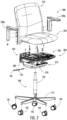
- the chair 1 comprises a base assembly 100, a seat assembly 200, and a backrest assembly 300.
- the seat assembly 200 is mounted to the base assembly 100, while the backrest assembly 300 is mounted to the seat assembly 200.
- the base assembly 100 may comprise any base known in the art for supporting a seat at a sufficient height for a user.
- the base assembly 100 comprises a base 110, a plurality of casters 105, and a column 120.
- the base 110 comprises five legs with individual casters 105 pivotally attached to the distal end of each leg.
- the column 120 comprises a height-adjustable, gas cylinder attached to the center of the base 110 to provide a pedestal on to which the seat assembly 200 may be mounted.
- other known base assemblies may be utilized.
- the base assembly 100 of the chair 1 may comprise four legs, a swivel pedestal, a cantilever base, or other known base assemblies commonly used with a seating apparatus.
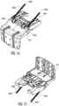
- the seat assembly 200 may comprise a housing subassembly 210, a connector subassembly 250, a seat plate subassembly 270, a shroud 280, a seat casing 285, and a seat 290.
- the housing subassembly 210 may be mounted to the column 120 using a fastener or other known means in the art.
- a handle subassembly 135 may be attached to the housing subassembly 210 and operatively coupled to the column 120 to provide a means for adjusting the level of extension of the column 120 and, consequently, the height of the seat 290.
- the connector subassembly 250 depicted in Figures 1-2 comprises a generally L-shaped connector 251 and functions to connect the backrest 310 to the seat 290.
- the vertical extension of the connector 251 may be partially disposed within a cavity formed within the backrest 310, and the horizontal extension of the connector 251 may be partially disposed with the housing 210.
- the seat plate subassembly 270 may be pivotally connected to the connector 251, with an optional shroud 280 being positioned over the seat plate subassembly 270.
- the bottom of the seat casing 285 may be mounted to the seat plate subassembly 270, and the seat 290 may be mounted to the top of the seat casing 285.
- the connector subassembly 250, the housing subassembly 210 and the seat plate subassembly 270 function together to provide the pivot mechanism for the backrest assembly 300.
- the backrest assembly 300 may comprise a backrest 310 and optional armrests 330a, 330b attached thereto.
- the backrest 310 may be operatively coupled to the vertical extension of the connector 251 such that when a rearward force is applied to the backrest, it is transferred to the connector 251.
- the backrest 310 is fixedly attached to the vertical extension of the connector 251 such that the backrest 310 does not pivot relative to the vertical extension of the connector 251.
- the backrest 310 may be pivotally coupled to the vertical extension of the connector 251.
- the armrests 330a, 330b may be mounted to the left and right sides of the backrest 310, respectively.
- the seat apparatus 1 features a backrest pivot mechanism comprising a connector 251 that interfaces with the seat assembly's housing 210 via a plurality of motion-facilitating components and corresponding ramps (each motion-facilitating component/ramp pairing referred to herein as a "ramp assemblage") positioned within the seat assembly 200 for providing a virtual pivot 400 for the backrest assembly 300.
- the backrest pivot mechanism comprises front, central and rear ramp assemblages, with the central and rear ramp assemblages operating in cooperation to provide the virtual pivot 400 for the backrest that is projected above the seat surface and forward of the backrest.
- the front ramp assemblage comprises right and left front glides 272a, 272b that engage right and left front housing ramps 215a, 215b.
- the central ramp assemblage comprises right and left central rollers 222a, 222b that engage arcuate connector ramps 255a, 255b.
- the rear ramp assemblage comprises right and left rear rollers 252a, 252b that engage right and left rear housing ramps 217a, 217b.
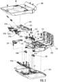
- the housing subassembly 210 can comprise a housing 211, right and left front housing ramps 215a, 215b positioned in the front portion of the housing 211, right and left rear housing ramps 217a, 217b positioned in the rear portion of the housing 211, a central post 213 positioned in the central portion of the housing 211, and right and left central rollers 222a, 222b mounted to the central post 213.
- the housing 211 can take the form of a generally rectangular tub defined by a bottom floor, two substantially parallel sidewalls, and a sloping front wall.
- Right and left front housing ramps 215a, 215b may be mounted to the front of the housing 211 in a position adjacent to the sloping front wall, while right and left rear ramps 217a, 217b may be mounted to the rear portion of the bottom floor of the housing 211.
- the front and rear ramps 215a, 215b, 217a, 217b may be separate components attached to the housing 211 using one or more fasteners.
- the front and rear ramps 215a, 215b, 217a, 217b may be integrally formed into the housing 211 during the molding process.
- the front housing ramps 215a, 215b are separate components fixedly attached to the housing 211, while the rear housing ramps 217a, 217b are integrally formed into the housing 211.
- a central post 213 may be attached to, or integrally formed with, the bottom floor of the housing 211 at a position between the front and rear of the housing 211.
- the central axle 223 may be positioned in a channel seat 214 (see Fig. 4 ) formed in the central post 213, with the axle cap 225 positioned over the front axle 223 to hold the central axle 223 in the seat 214.
- Right and left central rollers 222a, 222b may be attached to the right and left ends, respectively, of the central axle 223.
- the right and left central rollers 222a, 222b may take the form of other motion-facilitating components, such as glides, spherical balls, or any other structure capable of moving forwards and rearwards along the arcuate connector ramps 255a, 255b.
- the handle subassembly 135 may be operatively coupled to the central post 213 to provide a means for adjusting the level of extension of the column 120 and, consequently, the height of the seat 290.
- the handle subassembly 135 may comprise a height adjustment pivot lever 137 pivotally mounted to the central post 213.
- the second end of the pivot lever 137 is operatively coupled to the upper end of the column 120 (e.g., a gas cylinder) to selectively adjust the extension of the column 120.
- a handle 136 can be attached to the first end of the pivot lever 137 and extend through an aperture in the housing 211 to allow the user to toggle the handle subassembly 135 and adjust the height of the chair 1.
- a spring 139 can be operatively coupled to the first end of the pivot lever 137 to bias the pivot lever 137 in a first direction.
- a column fastener 113 can be utilized to secure the top end of the column 120 to the housing 210 (see Fig. 6 ).
- the connector subassembly 250 may comprise a connector 251, arcuate connector ramps 255, and rear rollers 252a, 252b.
- the connector 251 may generally be L-shaped with a horizontal extension and a vertical extension.
- the L-shaped connector is a rigid member that is substantially non-deformable under forces typically encountered during the seating apparatus' use (i.e., ⁇ 400 lbs).
- Arcuate connector ramps 255a, 255b may be attached to, or integrally formed in, the front end of the horizontal extension of the connector 251.
- the right and left rear rollers 252a, 252b may be rotatably coupled to the bottom of the connector 251.
- the right and left rear rollers 252a, 252b are positioned in slots formed in the bottom portion of the connector 251 proximate to the rear end of the horizontal extension.
- the right and left rear axles 253a, 253b extend through the right and left rear rollers 252a, 252b, respectively, to rotatably mount the rollers to the connector 251.
- the connector subassembly 250 is operatively coupled to the housing subassembly 210 by seating the right and left central rollers 222a, 222b of the housing subassembly within the right and left connector ramps 255a, 255b, respectively, of the connector subassembly 250. Meanwhile, the right and left rear rollers 252a, 252b of the connector subassembly 250 will engage the right and left rear ramps 217a, 217b, respectively, of the housing subassembly 210.
- Right and left connector retainers 212 may be utilized to assist with maintaining the coupling between connector 251 and the housing subassembly 210.
- one or more springs optionally may be attached between the connector 251 and the housing 211 to bias the seating apparatus in the upright position when the chair is unoccupied.
- the seating apparatus does not rely on a spring to increase or decrease the reclining counterbalance force.
- the spring merely provides a secondary force to overcome the weight of the chair components and maintain an unoccupied chair in an upright position.
- right and left spring assemblies are utilized and provide approximately 8 lbs of recline force at the center of gravity of the occupant's back at full recline.
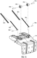
- the right spring subassembly comprises a spring piston 265a extending through a helical spring 267a.
- the left spring subassembly comprises a spring piston 265b extending through a helical spring 267b.
- the right and left spring pistons 265a, 265b each are pivotally attached to the base of the connector 250 via right and left pivot rods 266a, 266b.
- right and left spring retainers 220a, 220b may be attached to the bottom floor for coupling the distal ends of the right and left pivot rods 266a, 266b to the housing 210.
- the seat plate subassembly 270 may comprise a seat plate 271, a seat pivot 275, right and left front glides 272a, 272b, and right and left seat slide bearings 277a, 277b.
- the seat pivot 275 functions to provide a means for pivotally connecting the seat pivot 275 to the connector 251.
- the seat pivot 275 may be attached to the rear portion of the seat plate 271 at a first position and pivotally attached to right and left finger extensions 257a, 257b of the connector 251 at a second position.
- Right and left front glide members 272a, 272b may be attached to the front portion of the seat plate 271 and generally extend downward from the seat plate 271 such that the right and left front glides 272a, 272b engage the right and left front ramps 215a, 215b, respectively, of the housing subassembly 210.
- the right and left front glides 272a, 272b may take the form of other motion-facilitating components, such as rollers, spherical balls, or any other structure capable of moving forwards and rearwards along the ramps.
- Right and left seat slide bearings 277a, 277b may be attached to the top of the seat plate 271.
- the seat casing 285 may be mounted to seat plate 271 by attachment to the slide bearings 277a, 277b, with the seat 290 attached to the seat casing 285.
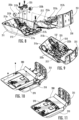
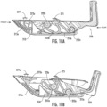
- FIG. 18-19 section views of the chair 1 are depicted in both the upright and reclined states, showing the interaction of the connector subassembly 250, housing subassembly 110, and seat plate subassembly 270 to provide the recline mechanism of the present invention.
- the seat plate subassembly 270 (and therefore the attached seat 290) is in a position generally parallel to the bottom floor of the housing 211, while the vertical extension of the connector 251(and therefore the attached backrest 310) is in a position generally perpendicular to the seat plate subassembly 270 and the bottom floor of the housing 211.
- the front, central and rear ramp assemblies are in the following states: the right and left front glides 272a, 272b are positioned at the rear (or bottom) portions of the right and left front housing ramps 215a, 215b; the central rollers 222a, 222b are positioned on the front portions of the right and left arcuate connector ramps 255a, 255b, respectively; and the rear rollers 252a, 252b are positioned on the rear portions of the right and left rear housing ramps 217a, 217b, respectively.
- the seat pivot 275 is positioned rearwardly of the central rollers 22a, 222b relative to the front of the chair 1.
- the front, central and rear ramp assemblies are in the following states: the right and left front glides 272a, 272b are positioned at the front (or top) portions of the right and left front housing ramps 215a, 215b, respectively; the central rollers 222a, 222b are positioned on the rear portions of the right and left arcuate connector ramps 255a, 255b, respectively; and the rear rollers 252a, 252b are positioned on the front portions of the right and left rear housing ramps 217a, 217b, respectively.
- the seat plate subassembly 270 (and therefore the attached seat 290) is pushed forward and upwards relative to the housing 211.
- the recline geometry and the ramp angles are optimized to minimize the vertical drop of the backrest during the recline motion, which in turn minimizes the seat lift during the recline motion.
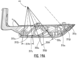
- the virtual pivot 400 is projected above the seating surface and is defined by the intersection of imaginary lines extending in a perpendicular fashion from the rear housing ramps 217a, 217b and the connector ramps 255a, 255b.
- Point 405 represents the positioning of a typical user's hip joints when the seating apparatus 1 is in the upright position.
- Arc 415 represents the path the rearward movement of the backrest 310 during recline, with the left side of the arc 415 representing the position of the backrest 310 in the upright position and the right side of the arc 415 representing the position of the backrest 310 in the reclined position.
- Point 410 represents the hip pivot point of the thigh at full reline
- point 412 represents the hip pivot point of the back at full recline. It is preferable that the ramp angles and chair geometry are optimized to provide for points 410 and 412 to remain as close together as possible during a recline action in order to make the reclining action of the seating apparatus 1 have a more natural feel and avoid the common shirt-pull problem associated with many reclinable chairs.
- a fully weight-sensitive seating apparatus can be provided that closely mimics the user's natural hip joint articulation during recline.
- FIG. 19A-19B A preferred embodiment of the seating apparatus 1 is depicted in Figures 19A-19B .
- the right and left rear housing ramps 217a, 217b generally have a rocker-shaped (i.e., reverse camber) side profile, with the ramp angle gradually decreasing from the rear portion of the ramps 217a, 217b to the center of the ramp, and the ramp angle gradually increasing from the center of the ramp to the front portion of the ramps 217a, 217b.
- the connector ramps 255a, 255b generally have a J-shaped side profile, with the ramp angle gradually increasing from the rear portion of the ramps 255a, 255b to the front portion of the ramps 255a, 255b.
- the rear housing ramps 217a, 217b and the connector ramps 255a, 255b collectively function to provide the virtual pivot 400 for the backrest assembly 300.
- the positioning of the virtual pivot 400 is dictated by the ramp angles of the rear housing ramps 217a, 217b and the connector ramps 255a, 255b.
- the virtual pivot 400 is projected above the seating surface and its location is defined by the intersection of imaginary lines extending in a perpendicular (i.e., 90°) fashion from the rear housing ramps 217a, 217b and the connector ramps 255a, 255b.
- the rear housing ramps 217a, 217b and the connector ramps 255a, 255b have lengths and ramp angles optimized to provide a virtual pivot point 400 positioned above the seat 290 and forward of the backrest 310.
- the chair 1's reclining mechanism in preferred embodiments will function to minimize both the vertical drop of the backrest and the lifting of the seat during the recline motion, thereby providing seating apparatus that relies on the user's weight for a vast majority of the recline resistance force (i.e., greater than 80% of the recline resistance force) while also maintaining the most ergonomic relationship as possible between the seat and the backrest throughout its range of motion.
- the width of the housing 211 is approximately 235 mm
- the length of the housing 211 is approximately 315 mm
- the depth of the housing 211 is approximately 75 mm.
- the distance between the central rollers 222a, 222b and the rear rollers 252a, 252b is approximately 125 mm
- the central rollers 222a, 222b are positioned approximately 50 mm above the bottom floor of the housing 211 as measured from the central axis of the central rollers 222a, 222b.
- the roller axle diameters for both the central and rear rollers is approximately 9 mm, while the rollers themselves have diameters of approximately 30 mm.
- the rear ends of the rear housing ramps 217a, 217b exhibit a ramp angle 217 ⁇ of approximately -9°; the center of the rear housing ramps 217a, 217b exhibit a ramp angle 217 ⁇ of approximately 0.0°; and the front ends of the rear housing ramps 217a, 217b exhibit a ramp angle 217 ⁇ of approximately +9°.
- the rear ends of the connector ramps 255a, 255b exhibit a ramp angle 255 ⁇ of approximately 20°; the center of the connector ramps 255a, 255b exhibit a ramp angle 255 ⁇ of approximately 29°; and the front ends of the connector ramps 255a, 255b exhibit a ramp angle 255 ⁇ of approximately 38°.
- the range of movement 217 ⁇ for the rear housing ramps 217a, 217b and the range of movement 255 ⁇ for the connector ramps 255a, 255b each are approximately 18° in the depicted embodiment. In alternative embodiments, the range of movement 255 ⁇ for the connector ramps 255a, 255b may range from approximately 15° to 25° in alternatives.
- the virtual pivot 400 is projected 120 mm above the seat surface 290 and 35 mm forward of the backrest 310.
- the median user's hip joint 405 is located approximately 60 mm above the seat surface 290 and approximately 100 mm forward of the backrest 310, which positions the median's user hip joint 405 approximately 50 mm behind the column 120.
- the seating apparatus preferably exhibits a front seat lift of approximately 1" ⁇ .25" and a rearward seat pitch of approximately 1-3 degrees between the upright position and the fully reclined position.
- the angles of the central connector ramps and rear housing ramps may be modified such that the virtual pivot 400 is projected 120 mm ⁇ 20 mm above the seat surface and 20 mm ⁇ 20 mm forward of the backrest, which is approximately 50-70 mm above and 60-80 mm behind the median user's hip joint 405.
- the front housing ramps 215a, 215b function to control the lifting of the front portion- and thus the tilt-of the seat plate subassembly 270 during recline.
- the front potion of the seat plate subassembly 270 is lifted slightly higher than the rear portion of the seat plate subassembly 270.
- the front housing ramps 215a, 215b generally have a sloped side profile, with the ramp angle gradually increasing from the rear portion of the ramps 215a, 215b to the front portion of the ramps 255a, 255b.
- the rear ends of the front housing ramps 215a, 215b exhibit a ramp angle 215 ⁇ of approximately 33°; the center of the front housing ramps 215a, 215b exhibit a ramp angle 215 ⁇ of approximately 41°; and the front ends of the front housing ramps 215a, 215b exhibit a ramp angle 215 ⁇ of approximately 49°.
- the ramp angles can vary according to various factors, including the sizing of the various components, the recline geometry, and the resistance provided by the friction introduced by the interaction of the motion facilitating components and the ramps. Because the load (i.e., the force) being applied against the backrest increases as the angle of the recline increases, the ramp angles of the rear housing ramps 217, connector ramps 255, and front housing ramps 215 preferably will vary across its length.
- the shape of the ramps and the motion-facilitating components may also vary.
- the ramps may by substantially linear in shape and the motion-facilitating components be nonuniform in shape.
- the motion-facilitating components may take the form of substantially oval-shaped rollers.
- the rollers may be spherical, but the ramps may have varying shapes (e.g., partially linear and partial curved), thereby allowing varying lift motions.
- the motion-facilitating component may take on a variety of forms.
- the component could be in the form of a roller shaped like a wheel.
- the rollers are spherical in nature.
- Such an embodiment is particularly beneficial for providing stability to the apparatus.
- the spherical shape increases the surface area of the roller in contact with the ramp, particularly when the ramp comprises a track having a concave shape (e.g., a valley running in the direction of travel) corresponding to the spherical rollers, thereby being particularly adapted for receiving the rollers. Accordingly, the roller becomes self-centering in the track and avoids drifts.
- the motion-facilitating components could include stationary low-friction glides or ball bearings.
- the rollers can be formed from metal or polymeric materials.
- the rollers are formed of low friction, high strength polymeric material, such as polytetrafluoroethylene (PTFE).
- the rollers comprise elastomeric materials, such as urethanes, which soften the action of the rolling movement across the ramps, thereby providing a smooth action.
- the ramps are similarly preferably formed of a material providing strength, durability, and, preferentially, reduced friction during interaction with the rollers. Exemplary materials for use in the ramps include, but are not limited to, high density polyethylene, high density polypropylene, PTFE, and the like.
Landscapes
- Health & Medical Sciences (AREA)
- Dentistry (AREA)
- General Health & Medical Sciences (AREA)
- Chairs For Special Purposes, Such As Reclining Chairs (AREA)
- Pharmaceuticals Containing Other Organic And Inorganic Compounds (AREA)
- Crystals, And After-Treatments Of Crystals (AREA)
- Saccharide Compounds (AREA)
Claims (5)
- Verstellbare Sitzvorrichtung (1), umfassend:(a) eine Sitzanordnung (200), umfassend ein Sitzgehäuse (211) und eine im Wesentlichen ebene Sitzplatte (271);(b) einen Rückenlehnenverstellmechanismus, umfassend:(i) ein Verbindungselement (251) mit einer horizontalen Verlängerung und einer vertikalen Verlängerung;(ii) eine zentrale Rampenanordnung zum funktionsfähigen Koppeln der horizontalen Verlängerung des Verbindungselements (251) mit einem zentralen Abschnitt des Sitzgehäuses (211), wobei die zentrale Rampenanordnung Folgendes umfasst: eine oder mehrere Verbindungsrampen (255), die an einem vorderen Abschnitt der horizontalen Verlängerung des Verbindungselements (251) positioniert sind; und eine oder mehrere zentrale Rollen (222), die an einem zentralen Pfosten (213) angebracht sind, der sich vertikal von einem Boden des Sitzgehäuses (211) erstreckt, wobei die eine oder die mehreren zentralen Rollen (222) mit der einen oder den mehreren Verbindungsrampen (255) funktionsfähig in Eingriff stehen und wobei die eine oder die mehreren Verbindungsrampen (255) jeweils ein J-förmiges Seitenprofil und eine Rampensteigung aufweisen, die einen Verbindungsrampenwinkel definiert, wobei der Verbindungsrampenwinkel von einem hinteren Ende jeder Rampe (255) zu einem vorderen Ende jeder Rampe (255) allmählich zunimmt; und(iii) eine hintere Rampenanordnung zum funktionsfähigen Koppeln der horizontalen Verlängerung des Verbindungselements mit einem hinteren Abschnitt des Sitzgehäuses, wobei die hintere Rampenanordnung Folgendes umfasst: eine oder mehrere hintere Gehäuserampen (217), die an einem hinteren Abschnitt des Sitzgehäuses (211) positioniert sind; und eine oder mehrere hintere Rollen (252), die an einem unteren Abschnitt der horizontalen Verlängerung des Verbindungselements (251) angebracht sind, wobei die eine oder die mehreren hinteren Rollen (252) mit der einen oder den mehreren hinteren Gehäuserampen (217) funktionsfähig in Eingriff stehen;(c) eine Rückenlehnenanordnung (300), die an der vertikalen Verlängerung des Verbindungselements (251) angebracht ist; undwobei:
ein hinterer Abschnitt der Sitzplatte (271) schwenkbar an dem Verbindungselement (251) angebracht ist und ein vorderer Abschnitt der Sitzplatte (271) funktionsfähig mit einem vorderen Abschnitt des Sitzgehäuses (200) gekoppelt ist, dadurch gekennzeichnet, dass der vordere Abschnitt der Sitzplatte (271) über eine vordere Rampenanordnung mit dem vorderen Abschnitt des Sitzgehäuses (200) funktionsfähig gekoppelt ist. - Verstellbare Sitzvorrichtung nach Anspruch 1, wobei die eine oder die mehreren hinteren Gehäuserampen (217) jeweils ein Seitenprofil mit umgekehrter Wölbung (Reverse Camber) und eine Rampensteigung aufweisen, die einen hinteren Rampenwinkel definiert, wobei der hintere Rampenwinkel von einem hinteren Ende jeder hinteren Gehäuserampe (217) zu einer Mitte jeder hinteren Gehäuserampe (217) allmählich abnimmt und wobei der hintere Rampenwinkel von der Mitte jeder hinteren Gehäuserampe (217) zu einem vorderen Ende jeder hinteren Gehäuserampe (217) allmählich zunimmt.
- Verstellbare Sitzvorrichtung nach Anspruch 2, wobei der hintere Rampenwinkel der einen oder der mehreren hinteren Gehäuserampen (217) von etwa -9° am hinteren Ende der einen oder der mehreren hinteren Gehäuserampen bis etwa +9° am vorderen Ende der einen oder der mehreren hinteren Gehäuserampen (217) variiert.
- Verstellbare Sitzvorrichtung nach Anspruch 1, wobei der Verbindungsrampenwinkel der einen oder der mehreren Verbindungsrampen (255) von etwa +20° am hinteren Ende der einen oder der mehreren Verbindungsrampen (255) bis zu etwa +38° am vorderen Ende der einen oder der mehreren hinteren Gehäuserampen (255) progressiv zunimmt.
- Verstellbare Sitzvorrichtung nach Anspruch 1, wobei die vordere Rampenanordnung eine oder mehrere vordere Gehäuserampen (215) umfasst, die mit einer oder mehreren vorderen Rollen (272) in Eingriff stehen, wobei die eine oder die mehreren vorderen Gehäuserampen (215) am vorderen Abschnitt des Gehäuses (211) positioniert sind und wobei die eine oder die mehreren hinteren Rollen (272) an einer unteren Oberfläche der Sitzplatte (271) angebracht sind.
Applications Claiming Priority (2)
| Application Number | Priority Date | Filing Date | Title |
|---|---|---|---|
| US202063122890P | 2020-12-08 | 2020-12-08 | |
| PCT/US2021/062404 WO2022125662A1 (en) | 2020-12-08 | 2021-12-08 | Reclinable seating apparatus |
Publications (2)
| Publication Number | Publication Date |
|---|---|
| EP4258944A1 EP4258944A1 (de) | 2023-10-18 |
| EP4258944B1 true EP4258944B1 (de) | 2025-04-30 |
Family
ID=79164652
Family Applications (1)
| Application Number | Title | Priority Date | Filing Date |
|---|---|---|---|
| EP21835108.8A Active EP4258944B1 (de) | 2020-12-08 | 2021-12-08 | Neigungsverstellbare sitzvorrichtung |
Country Status (6)
| Country | Link |
|---|---|
| US (1) | US12471708B2 (de) |
| EP (1) | EP4258944B1 (de) |
| CN (1) | CN116963642A (de) |
| AU (1) | AU2021396526A1 (de) |
| CA (1) | CA3204720A1 (de) |
| WO (1) | WO2022125662A1 (de) |
Family Cites Families (20)
| Publication number | Priority date | Publication date | Assignee | Title |
|---|---|---|---|---|
| FR1596508A (de) * | 1968-07-18 | 1970-06-22 | ||
| NO160896C (no) * | 1986-05-09 | 1989-06-14 | Jurek Buchacz | Stillbar sitteanordning. |
| JPH01297009A (ja) * | 1987-12-28 | 1989-11-30 | Isao Hosoe | 人間工学的椅子の座面 |
| US5333368A (en) * | 1992-09-08 | 1994-08-02 | Haworth, Inc. | Chair control with forward tilt |
| NO300754B1 (no) | 1994-10-14 | 1997-07-21 | Handicare Ind As | Anordning ved stillbar stol |
| US5603551A (en) * | 1996-01-16 | 1997-02-18 | Sheehan; Kelly | Gravitational resistant positional chair |
| US5967609A (en) * | 1996-11-18 | 1999-10-19 | Hwe, Inc. | Reclining chair with guide rail system |
| US6106065A (en) * | 1997-10-24 | 2000-08-22 | Reliance Medical Products, Inc. | Examination chair with lifting and tilting mechanism |
| IT1306152B1 (it) * | 1999-06-02 | 2001-05-30 | Aviointeriors Spa | Poltrona con movimento a culla perfezionato, in particolare peraeromobili. |
| US7090240B2 (en) * | 2002-10-28 | 2006-08-15 | Plainsense Wheelchairs, Inc. | Tiltable seating apparatus for wheelchair |
| US6945602B2 (en) * | 2003-12-18 | 2005-09-20 | Haworth, Inc. | Tilt control mechanism for chair |
| AR057387A1 (es) | 2005-06-20 | 2007-12-05 | Humanscale Corp | Aparato de asiento con movimiento reclinable |
| WO2009048448A1 (en) * | 2006-10-10 | 2009-04-16 | Hector Serber | Dynamically balanced seat assembly |
| KR100968547B1 (ko) | 2008-03-27 | 2010-07-08 | 듀오백코리아 주식회사 | 의자의 틸팅 장치 |
| EP2608699B1 (de) * | 2010-08-25 | 2015-11-25 | L&P Property Management Company | Neigungsmechanismus für einen stuhl und stuhl |
| GB201015414D0 (en) * | 2010-09-15 | 2010-10-27 | Birkbeck Hilary R | Link chair action |
| US9462889B2 (en) * | 2014-02-13 | 2016-10-11 | Pro-Cord S.P.A. | Chair with a seat and backrest movable in a synchronized way |
| WO2015167205A1 (ko) * | 2014-04-30 | 2015-11-05 | 한국생산기술연구원 | 의자 틸팅장치 |
| GB201901010D0 (en) * | 2019-01-24 | 2019-03-13 | Eevolv Ltd | Lay-flat chair |
| WO2020252191A1 (en) * | 2019-06-11 | 2020-12-17 | Herman Miller, Inc. | Chair |
-
2021
- 2021-12-08 AU AU2021396526A patent/AU2021396526A1/en active Pending
- 2021-12-08 CA CA3204720A patent/CA3204720A1/en active Pending
- 2021-12-08 CN CN202180081948.2A patent/CN116963642A/zh active Pending
- 2021-12-08 US US18/265,608 patent/US12471708B2/en active Active
- 2021-12-08 EP EP21835108.8A patent/EP4258944B1/de active Active
- 2021-12-08 WO PCT/US2021/062404 patent/WO2022125662A1/en not_active Ceased
Also Published As
| Publication number | Publication date |
|---|---|
| CN116963642A (zh) | 2023-10-27 |
| WO2022125662A1 (en) | 2022-06-16 |
| AU2021396526A1 (en) | 2023-06-29 |
| AU2021396526A9 (en) | 2024-05-02 |
| US12471708B2 (en) | 2025-11-18 |
| CA3204720A1 (en) | 2022-06-16 |
| US20240023712A1 (en) | 2024-01-25 |
| EP4258944A1 (de) | 2023-10-18 |
Similar Documents
| Publication | Publication Date | Title |
|---|---|---|
| CA2808205C (en) | Tilt mechanism for a chair and chair | |
| US7806478B1 (en) | Task chair with dual tilting capabilities | |
| US6913315B2 (en) | Chair construction | |
| JP3162325B2 (ja) | 背もたれおよび座席の調整が連動している、腰掛け用家具部材 | |
| US6709058B1 (en) | Ergonomic chair | |
| CA2394954C (en) | Ergonomic chair | |
| US11969094B2 (en) | Chair | |
| EP3788912B1 (de) | Stuhlanordnung | |
| CA2814510A1 (en) | Ergonomic adjustable chair mechanisms | |
| CN106455819B (zh) | 座椅后倾机构、可调节座椅组件及方法 | |
| CA3025252A1 (en) | Chair and seat support mechanism | |
| EP4258944B1 (de) | Neigungsverstellbare sitzvorrichtung | |
| EP4213685B1 (de) | Verstellbarer stuhl | |
| CA3061627C (en) | Reclining chair with improved stability | |
| MXPA97006723A (en) | Component of a furniture to sit or similar with adjusting the back and seat coupled | |
| HK1236077A1 (en) | Seat recline mechanism, adjustable seating assembly, and method | |
| HK1236077B (en) | Seat recline mechanism, adjustable seating assembly, and method |
Legal Events
| Date | Code | Title | Description |
|---|---|---|---|
| STAA | Information on the status of an ep patent application or granted ep patent |
Free format text: STATUS: UNKNOWN |
|
| STAA | Information on the status of an ep patent application or granted ep patent |
Free format text: STATUS: THE INTERNATIONAL PUBLICATION HAS BEEN MADE |
|
| PUAI | Public reference made under article 153(3) epc to a published international application that has entered the european phase |
Free format text: ORIGINAL CODE: 0009012 |
|
| STAA | Information on the status of an ep patent application or granted ep patent |
Free format text: STATUS: REQUEST FOR EXAMINATION WAS MADE |
|
| 17P | Request for examination filed |
Effective date: 20230630 |
|
| AK | Designated contracting states |
Kind code of ref document: A1 Designated state(s): AL AT BE BG CH CY CZ DE DK EE ES FI FR GB GR HR HU IE IS IT LI LT LU LV MC MK MT NL NO PL PT RO RS SE SI SK SM TR |
|
| DAV | Request for validation of the european patent (deleted) | ||
| DAX | Request for extension of the european patent (deleted) | ||
| STAA | Information on the status of an ep patent application or granted ep patent |
Free format text: STATUS: EXAMINATION IS IN PROGRESS |
|
| 17Q | First examination report despatched |
Effective date: 20240513 |
|
| GRAP | Despatch of communication of intention to grant a patent |
Free format text: ORIGINAL CODE: EPIDOSNIGR1 |
|
| STAA | Information on the status of an ep patent application or granted ep patent |
Free format text: STATUS: GRANT OF PATENT IS INTENDED |
|
| INTG | Intention to grant announced |
Effective date: 20241125 |
|
| GRAS | Grant fee paid |
Free format text: ORIGINAL CODE: EPIDOSNIGR3 |
|
| GRAA | (expected) grant |
Free format text: ORIGINAL CODE: 0009210 |
|
| STAA | Information on the status of an ep patent application or granted ep patent |
Free format text: STATUS: THE PATENT HAS BEEN GRANTED |
|
| AK | Designated contracting states |
Kind code of ref document: B1 Designated state(s): AL AT BE BG CH CY CZ DE DK EE ES FI FR GB GR HR HU IE IS IT LI LT LU LV MC MK MT NL NO PL PT RO RS SE SI SK SM TR |
|
| P01 | Opt-out of the competence of the unified patent court (upc) registered |
Free format text: CASE NUMBER: APP_14599/2025 Effective date: 20250325 |
|
| REG | Reference to a national code |
Ref country code: CH Ref legal event code: EP Ref country code: GB Ref legal event code: FG4D |
|
| REG | Reference to a national code |
Ref country code: IE Ref legal event code: FG4D |
|
| REG | Reference to a national code |
Ref country code: DE Ref legal event code: R096 Ref document number: 602021030140 Country of ref document: DE |
|
| REG | Reference to a national code |
Ref country code: NL Ref legal event code: MP Effective date: 20250430 |
|
| REG | Reference to a national code |
Ref country code: AT Ref legal event code: MK05 Ref document number: 1789209 Country of ref document: AT Kind code of ref document: T Effective date: 20250430 |
|
| PG25 | Lapsed in a contracting state [announced via postgrant information from national office to epo] |
Ref country code: PT Free format text: LAPSE BECAUSE OF FAILURE TO SUBMIT A TRANSLATION OF THE DESCRIPTION OR TO PAY THE FEE WITHIN THE PRESCRIBED TIME-LIMIT Effective date: 20250901 Ref country code: FI Free format text: LAPSE BECAUSE OF FAILURE TO SUBMIT A TRANSLATION OF THE DESCRIPTION OR TO PAY THE FEE WITHIN THE PRESCRIBED TIME-LIMIT Effective date: 20250430 Ref country code: ES Free format text: LAPSE BECAUSE OF FAILURE TO SUBMIT A TRANSLATION OF THE DESCRIPTION OR TO PAY THE FEE WITHIN THE PRESCRIBED TIME-LIMIT Effective date: 20250430 |
|
| REG | Reference to a national code |
Ref country code: LT Ref legal event code: MG9D |
|
| PG25 | Lapsed in a contracting state [announced via postgrant information from national office to epo] |
Ref country code: NO Free format text: LAPSE BECAUSE OF FAILURE TO SUBMIT A TRANSLATION OF THE DESCRIPTION OR TO PAY THE FEE WITHIN THE PRESCRIBED TIME-LIMIT Effective date: 20250730 Ref country code: GR Free format text: LAPSE BECAUSE OF FAILURE TO SUBMIT A TRANSLATION OF THE DESCRIPTION OR TO PAY THE FEE WITHIN THE PRESCRIBED TIME-LIMIT Effective date: 20250731 |
|
| PG25 | Lapsed in a contracting state [announced via postgrant information from national office to epo] |
Ref country code: NL Free format text: LAPSE BECAUSE OF FAILURE TO SUBMIT A TRANSLATION OF THE DESCRIPTION OR TO PAY THE FEE WITHIN THE PRESCRIBED TIME-LIMIT Effective date: 20250430 Ref country code: PL Free format text: LAPSE BECAUSE OF FAILURE TO SUBMIT A TRANSLATION OF THE DESCRIPTION OR TO PAY THE FEE WITHIN THE PRESCRIBED TIME-LIMIT Effective date: 20250430 |
|
| PG25 | Lapsed in a contracting state [announced via postgrant information from national office to epo] |
Ref country code: BG Free format text: LAPSE BECAUSE OF FAILURE TO SUBMIT A TRANSLATION OF THE DESCRIPTION OR TO PAY THE FEE WITHIN THE PRESCRIBED TIME-LIMIT Effective date: 20250430 |
|
| PG25 | Lapsed in a contracting state [announced via postgrant information from national office to epo] |
Ref country code: HR Free format text: LAPSE BECAUSE OF FAILURE TO SUBMIT A TRANSLATION OF THE DESCRIPTION OR TO PAY THE FEE WITHIN THE PRESCRIBED TIME-LIMIT Effective date: 20250430 |
|
| PG25 | Lapsed in a contracting state [announced via postgrant information from national office to epo] |
Ref country code: AT Free format text: LAPSE BECAUSE OF FAILURE TO SUBMIT A TRANSLATION OF THE DESCRIPTION OR TO PAY THE FEE WITHIN THE PRESCRIBED TIME-LIMIT Effective date: 20250430 |
|
| PG25 | Lapsed in a contracting state [announced via postgrant information from national office to epo] |
Ref country code: RS Free format text: LAPSE BECAUSE OF FAILURE TO SUBMIT A TRANSLATION OF THE DESCRIPTION OR TO PAY THE FEE WITHIN THE PRESCRIBED TIME-LIMIT Effective date: 20250731 |
|
| PG25 | Lapsed in a contracting state [announced via postgrant information from national office to epo] |
Ref country code: IS Free format text: LAPSE BECAUSE OF FAILURE TO SUBMIT A TRANSLATION OF THE DESCRIPTION OR TO PAY THE FEE WITHIN THE PRESCRIBED TIME-LIMIT Effective date: 20250830 |
|
| PG25 | Lapsed in a contracting state [announced via postgrant information from national office to epo] |
Ref country code: LV Free format text: LAPSE BECAUSE OF FAILURE TO SUBMIT A TRANSLATION OF THE DESCRIPTION OR TO PAY THE FEE WITHIN THE PRESCRIBED TIME-LIMIT Effective date: 20250430 |
|
| PGFP | Annual fee paid to national office [announced via postgrant information from national office to epo] |
Ref country code: GB Payment date: 20251229 Year of fee payment: 5 |
|
| PG25 | Lapsed in a contracting state [announced via postgrant information from national office to epo] |
Ref country code: SM Free format text: LAPSE BECAUSE OF FAILURE TO SUBMIT A TRANSLATION OF THE DESCRIPTION OR TO PAY THE FEE WITHIN THE PRESCRIBED TIME-LIMIT Effective date: 20250430 Ref country code: DK Free format text: LAPSE BECAUSE OF FAILURE TO SUBMIT A TRANSLATION OF THE DESCRIPTION OR TO PAY THE FEE WITHIN THE PRESCRIBED TIME-LIMIT Effective date: 20250430 |
|
| PGFP | Annual fee paid to national office [announced via postgrant information from national office to epo] |
Ref country code: FR Payment date: 20251226 Year of fee payment: 5 |
|
| PG25 | Lapsed in a contracting state [announced via postgrant information from national office to epo] |
Ref country code: CZ Free format text: LAPSE BECAUSE OF FAILURE TO SUBMIT A TRANSLATION OF THE DESCRIPTION OR TO PAY THE FEE WITHIN THE PRESCRIBED TIME-LIMIT Effective date: 20250430 |
|
| PGFP | Annual fee paid to national office [announced via postgrant information from national office to epo] |
Ref country code: IE Payment date: 20251229 Year of fee payment: 5 |
|
| PG25 | Lapsed in a contracting state [announced via postgrant information from national office to epo] |
Ref country code: EE Free format text: LAPSE BECAUSE OF FAILURE TO SUBMIT A TRANSLATION OF THE DESCRIPTION OR TO PAY THE FEE WITHIN THE PRESCRIBED TIME-LIMIT Effective date: 20250430 |
|
| PG25 | Lapsed in a contracting state [announced via postgrant information from national office to epo] |
Ref country code: SK Free format text: LAPSE BECAUSE OF FAILURE TO SUBMIT A TRANSLATION OF THE DESCRIPTION OR TO PAY THE FEE WITHIN THE PRESCRIBED TIME-LIMIT Effective date: 20250430 |
|
| PG25 | Lapsed in a contracting state [announced via postgrant information from national office to epo] |
Ref country code: IT Free format text: LAPSE BECAUSE OF FAILURE TO SUBMIT A TRANSLATION OF THE DESCRIPTION OR TO PAY THE FEE WITHIN THE PRESCRIBED TIME-LIMIT Effective date: 20250430 |
|
| REG | Reference to a national code |
Ref country code: DE Ref legal event code: R097 Ref document number: 602021030140 Country of ref document: DE |
|
| PG25 | Lapsed in a contracting state [announced via postgrant information from national office to epo] |
Ref country code: RO Free format text: LAPSE BECAUSE OF FAILURE TO SUBMIT A TRANSLATION OF THE DESCRIPTION OR TO PAY THE FEE WITHIN THE PRESCRIBED TIME-LIMIT Effective date: 20250430 |
|
| PLBE | No opposition filed within time limit |
Free format text: ORIGINAL CODE: 0009261 |
|
| STAA | Information on the status of an ep patent application or granted ep patent |
Free format text: STATUS: NO OPPOSITION FILED WITHIN TIME LIMIT |
|
| REG | Reference to a national code |
Ref country code: CH Ref legal event code: L10 Free format text: ST27 STATUS EVENT CODE: U-0-0-L10-L00 (AS PROVIDED BY THE NATIONAL OFFICE) Effective date: 20260311 |