EP4258540A1 - Antriebsvorrichtung und antriebsverfahren für elektrische drehmaschine und schienenfahrzeug - Google Patents
Antriebsvorrichtung und antriebsverfahren für elektrische drehmaschine und schienenfahrzeug Download PDFInfo
- Publication number
- EP4258540A1 EP4258540A1 EP21900575.8A EP21900575A EP4258540A1 EP 4258540 A1 EP4258540 A1 EP 4258540A1 EP 21900575 A EP21900575 A EP 21900575A EP 4258540 A1 EP4258540 A1 EP 4258540A1
- Authority
- EP
- European Patent Office
- Prior art keywords
- electric machine
- rotary electric
- slip
- slide
- value
- Prior art date
- Legal status (The legal status is an assumption and is not a legal conclusion. Google has not performed a legal analysis and makes no representation as to the accuracy of the status listed.)
- Granted
Links
Images


Classifications
-
- B—PERFORMING OPERATIONS; TRANSPORTING
- B60—VEHICLES IN GENERAL
- B60L—PROPULSION OF ELECTRICALLY-PROPELLED VEHICLES; SUPPLYING ELECTRIC POWER FOR AUXILIARY EQUIPMENT OF ELECTRICALLY-PROPELLED VEHICLES; ELECTRODYNAMIC BRAKE SYSTEMS FOR VEHICLES IN GENERAL; MAGNETIC SUSPENSION OR LEVITATION FOR VEHICLES; MONITORING OPERATING VARIABLES OF ELECTRICALLY-PROPELLED VEHICLES; ELECTRIC SAFETY DEVICES FOR ELECTRICALLY-PROPELLED VEHICLES
- B60L15/00—Methods, circuits, or devices for controlling the traction-motor speed of electrically-propelled vehicles
- B60L15/02—Methods, circuits, or devices for controlling the traction-motor speed of electrically-propelled vehicles characterised by the form of the current used in the control circuit
- B60L15/025—Methods, circuits, or devices for controlling the traction-motor speed of electrically-propelled vehicles characterised by the form of the current used in the control circuit using field orientation; Vector control; Direct Torque Control [DTC]
-
- B—PERFORMING OPERATIONS; TRANSPORTING
- B60—VEHICLES IN GENERAL
- B60L—PROPULSION OF ELECTRICALLY-PROPELLED VEHICLES; SUPPLYING ELECTRIC POWER FOR AUXILIARY EQUIPMENT OF ELECTRICALLY-PROPELLED VEHICLES; ELECTRODYNAMIC BRAKE SYSTEMS FOR VEHICLES IN GENERAL; MAGNETIC SUSPENSION OR LEVITATION FOR VEHICLES; MONITORING OPERATING VARIABLES OF ELECTRICALLY-PROPELLED VEHICLES; ELECTRIC SAFETY DEVICES FOR ELECTRICALLY-PROPELLED VEHICLES
- B60L15/00—Methods, circuits, or devices for controlling the traction-motor speed of electrically-propelled vehicles
- B60L15/32—Control or regulation of multiple-unit electrically-propelled vehicles
- B60L15/38—Control or regulation of multiple-unit electrically-propelled vehicles with automatic control
-
- B—PERFORMING OPERATIONS; TRANSPORTING
- B60—VEHICLES IN GENERAL
- B60L—PROPULSION OF ELECTRICALLY-PROPELLED VEHICLES; SUPPLYING ELECTRIC POWER FOR AUXILIARY EQUIPMENT OF ELECTRICALLY-PROPELLED VEHICLES; ELECTRODYNAMIC BRAKE SYSTEMS FOR VEHICLES IN GENERAL; MAGNETIC SUSPENSION OR LEVITATION FOR VEHICLES; MONITORING OPERATING VARIABLES OF ELECTRICALLY-PROPELLED VEHICLES; ELECTRIC SAFETY DEVICES FOR ELECTRICALLY-PROPELLED VEHICLES
- B60L3/00—Electric devices on electrically-propelled vehicles for safety purposes; Monitoring operating variables, e.g. speed, deceleration or energy consumption
- B60L3/10—Indicating wheel slip ; Correction of wheel slip
- B60L3/102—Indicating wheel slip ; Correction of wheel slip of individual wheels
-
- B—PERFORMING OPERATIONS; TRANSPORTING
- B60—VEHICLES IN GENERAL
- B60L—PROPULSION OF ELECTRICALLY-PROPELLED VEHICLES; SUPPLYING ELECTRIC POWER FOR AUXILIARY EQUIPMENT OF ELECTRICALLY-PROPELLED VEHICLES; ELECTRODYNAMIC BRAKE SYSTEMS FOR VEHICLES IN GENERAL; MAGNETIC SUSPENSION OR LEVITATION FOR VEHICLES; MONITORING OPERATING VARIABLES OF ELECTRICALLY-PROPELLED VEHICLES; ELECTRIC SAFETY DEVICES FOR ELECTRICALLY-PROPELLED VEHICLES
- B60L3/00—Electric devices on electrically-propelled vehicles for safety purposes; Monitoring operating variables, e.g. speed, deceleration or energy consumption
- B60L3/10—Indicating wheel slip ; Correction of wheel slip
- B60L3/104—Indicating wheel slip ; Correction of wheel slip by indirect measurement of vehicle speed
-
- B—PERFORMING OPERATIONS; TRANSPORTING
- B60—VEHICLES IN GENERAL
- B60L—PROPULSION OF ELECTRICALLY-PROPELLED VEHICLES; SUPPLYING ELECTRIC POWER FOR AUXILIARY EQUIPMENT OF ELECTRICALLY-PROPELLED VEHICLES; ELECTRODYNAMIC BRAKE SYSTEMS FOR VEHICLES IN GENERAL; MAGNETIC SUSPENSION OR LEVITATION FOR VEHICLES; MONITORING OPERATING VARIABLES OF ELECTRICALLY-PROPELLED VEHICLES; ELECTRIC SAFETY DEVICES FOR ELECTRICALLY-PROPELLED VEHICLES
- B60L3/00—Electric devices on electrically-propelled vehicles for safety purposes; Monitoring operating variables, e.g. speed, deceleration or energy consumption
- B60L3/10—Indicating wheel slip ; Correction of wheel slip
- B60L3/106—Indicating wheel slip ; Correction of wheel slip for maintaining or recovering the adhesion of the drive wheels
-
- B—PERFORMING OPERATIONS; TRANSPORTING
- B60—VEHICLES IN GENERAL
- B60L—PROPULSION OF ELECTRICALLY-PROPELLED VEHICLES; SUPPLYING ELECTRIC POWER FOR AUXILIARY EQUIPMENT OF ELECTRICALLY-PROPELLED VEHICLES; ELECTRODYNAMIC BRAKE SYSTEMS FOR VEHICLES IN GENERAL; MAGNETIC SUSPENSION OR LEVITATION FOR VEHICLES; MONITORING OPERATING VARIABLES OF ELECTRICALLY-PROPELLED VEHICLES; ELECTRIC SAFETY DEVICES FOR ELECTRICALLY-PROPELLED VEHICLES
- B60L3/00—Electric devices on electrically-propelled vehicles for safety purposes; Monitoring operating variables, e.g. speed, deceleration or energy consumption
- B60L3/12—Recording operating variables ; Monitoring of operating variables
-
- H—ELECTRICITY
- H02—GENERATION; CONVERSION OR DISTRIBUTION OF ELECTRIC POWER
- H02P—CONTROL OR REGULATION OF ELECTRIC MOTORS, ELECTRIC GENERATORS OR DYNAMO-ELECTRIC CONVERTERS; CONTROLLING TRANSFORMERS, REACTORS OR CHOKE COILS
- H02P21/00—Arrangements or methods for the control of electric machines by vector control, e.g. by control of field orientation
- H02P21/14—Estimation or adaptation of machine parameters, e.g. flux, current or voltage
- H02P21/18—Estimation of position or speed
-
- B—PERFORMING OPERATIONS; TRANSPORTING
- B60—VEHICLES IN GENERAL
- B60L—PROPULSION OF ELECTRICALLY-PROPELLED VEHICLES; SUPPLYING ELECTRIC POWER FOR AUXILIARY EQUIPMENT OF ELECTRICALLY-PROPELLED VEHICLES; ELECTRODYNAMIC BRAKE SYSTEMS FOR VEHICLES IN GENERAL; MAGNETIC SUSPENSION OR LEVITATION FOR VEHICLES; MONITORING OPERATING VARIABLES OF ELECTRICALLY-PROPELLED VEHICLES; ELECTRIC SAFETY DEVICES FOR ELECTRICALLY-PROPELLED VEHICLES
- B60L2200/00—Type of vehicles
- B60L2200/26—Rail vehicles
-
- B—PERFORMING OPERATIONS; TRANSPORTING
- B60—VEHICLES IN GENERAL
- B60L—PROPULSION OF ELECTRICALLY-PROPELLED VEHICLES; SUPPLYING ELECTRIC POWER FOR AUXILIARY EQUIPMENT OF ELECTRICALLY-PROPELLED VEHICLES; ELECTRODYNAMIC BRAKE SYSTEMS FOR VEHICLES IN GENERAL; MAGNETIC SUSPENSION OR LEVITATION FOR VEHICLES; MONITORING OPERATING VARIABLES OF ELECTRICALLY-PROPELLED VEHICLES; ELECTRIC SAFETY DEVICES FOR ELECTRICALLY-PROPELLED VEHICLES
- B60L2220/00—Electrical machine types; Structures or applications thereof
- B60L2220/10—Electrical machine types
- B60L2220/12—Induction machines
-
- B—PERFORMING OPERATIONS; TRANSPORTING
- B60—VEHICLES IN GENERAL
- B60L—PROPULSION OF ELECTRICALLY-PROPELLED VEHICLES; SUPPLYING ELECTRIC POWER FOR AUXILIARY EQUIPMENT OF ELECTRICALLY-PROPELLED VEHICLES; ELECTRODYNAMIC BRAKE SYSTEMS FOR VEHICLES IN GENERAL; MAGNETIC SUSPENSION OR LEVITATION FOR VEHICLES; MONITORING OPERATING VARIABLES OF ELECTRICALLY-PROPELLED VEHICLES; ELECTRIC SAFETY DEVICES FOR ELECTRICALLY-PROPELLED VEHICLES
- B60L2220/00—Electrical machine types; Structures or applications thereof
- B60L2220/10—Electrical machine types
- B60L2220/14—Synchronous machines
-
- B—PERFORMING OPERATIONS; TRANSPORTING
- B60—VEHICLES IN GENERAL
- B60L—PROPULSION OF ELECTRICALLY-PROPELLED VEHICLES; SUPPLYING ELECTRIC POWER FOR AUXILIARY EQUIPMENT OF ELECTRICALLY-PROPELLED VEHICLES; ELECTRODYNAMIC BRAKE SYSTEMS FOR VEHICLES IN GENERAL; MAGNETIC SUSPENSION OR LEVITATION FOR VEHICLES; MONITORING OPERATING VARIABLES OF ELECTRICALLY-PROPELLED VEHICLES; ELECTRIC SAFETY DEVICES FOR ELECTRICALLY-PROPELLED VEHICLES
- B60L2240/00—Control parameters of input or output; Target parameters
- B60L2240/10—Vehicle control parameters
- B60L2240/12—Speed
-
- B—PERFORMING OPERATIONS; TRANSPORTING
- B60—VEHICLES IN GENERAL
- B60L—PROPULSION OF ELECTRICALLY-PROPELLED VEHICLES; SUPPLYING ELECTRIC POWER FOR AUXILIARY EQUIPMENT OF ELECTRICALLY-PROPELLED VEHICLES; ELECTRODYNAMIC BRAKE SYSTEMS FOR VEHICLES IN GENERAL; MAGNETIC SUSPENSION OR LEVITATION FOR VEHICLES; MONITORING OPERATING VARIABLES OF ELECTRICALLY-PROPELLED VEHICLES; ELECTRIC SAFETY DEVICES FOR ELECTRICALLY-PROPELLED VEHICLES
- B60L2240/00—Control parameters of input or output; Target parameters
- B60L2240/10—Vehicle control parameters
- B60L2240/26—Vehicle weight
-
- B—PERFORMING OPERATIONS; TRANSPORTING
- B60—VEHICLES IN GENERAL
- B60L—PROPULSION OF ELECTRICALLY-PROPELLED VEHICLES; SUPPLYING ELECTRIC POWER FOR AUXILIARY EQUIPMENT OF ELECTRICALLY-PROPELLED VEHICLES; ELECTRODYNAMIC BRAKE SYSTEMS FOR VEHICLES IN GENERAL; MAGNETIC SUSPENSION OR LEVITATION FOR VEHICLES; MONITORING OPERATING VARIABLES OF ELECTRICALLY-PROPELLED VEHICLES; ELECTRIC SAFETY DEVICES FOR ELECTRICALLY-PROPELLED VEHICLES
- B60L2240/00—Control parameters of input or output; Target parameters
- B60L2240/10—Vehicle control parameters
- B60L2240/32—Driving direction
-
- B—PERFORMING OPERATIONS; TRANSPORTING
- B60—VEHICLES IN GENERAL
- B60L—PROPULSION OF ELECTRICALLY-PROPELLED VEHICLES; SUPPLYING ELECTRIC POWER FOR AUXILIARY EQUIPMENT OF ELECTRICALLY-PROPELLED VEHICLES; ELECTRODYNAMIC BRAKE SYSTEMS FOR VEHICLES IN GENERAL; MAGNETIC SUSPENSION OR LEVITATION FOR VEHICLES; MONITORING OPERATING VARIABLES OF ELECTRICALLY-PROPELLED VEHICLES; ELECTRIC SAFETY DEVICES FOR ELECTRICALLY-PROPELLED VEHICLES
- B60L2240/00—Control parameters of input or output; Target parameters
- B60L2240/40—Drive Train control parameters
- B60L2240/42—Drive Train control parameters related to electric machines
- B60L2240/421—Speed
-
- B—PERFORMING OPERATIONS; TRANSPORTING
- B60—VEHICLES IN GENERAL
- B60L—PROPULSION OF ELECTRICALLY-PROPELLED VEHICLES; SUPPLYING ELECTRIC POWER FOR AUXILIARY EQUIPMENT OF ELECTRICALLY-PROPELLED VEHICLES; ELECTRODYNAMIC BRAKE SYSTEMS FOR VEHICLES IN GENERAL; MAGNETIC SUSPENSION OR LEVITATION FOR VEHICLES; MONITORING OPERATING VARIABLES OF ELECTRICALLY-PROPELLED VEHICLES; ELECTRIC SAFETY DEVICES FOR ELECTRICALLY-PROPELLED VEHICLES
- B60L2240/00—Control parameters of input or output; Target parameters
- B60L2240/40—Drive Train control parameters
- B60L2240/42—Drive Train control parameters related to electric machines
- B60L2240/423—Torque
-
- B—PERFORMING OPERATIONS; TRANSPORTING
- B60—VEHICLES IN GENERAL
- B60L—PROPULSION OF ELECTRICALLY-PROPELLED VEHICLES; SUPPLYING ELECTRIC POWER FOR AUXILIARY EQUIPMENT OF ELECTRICALLY-PROPELLED VEHICLES; ELECTRODYNAMIC BRAKE SYSTEMS FOR VEHICLES IN GENERAL; MAGNETIC SUSPENSION OR LEVITATION FOR VEHICLES; MONITORING OPERATING VARIABLES OF ELECTRICALLY-PROPELLED VEHICLES; ELECTRIC SAFETY DEVICES FOR ELECTRICALLY-PROPELLED VEHICLES
- B60L2240/00—Control parameters of input or output; Target parameters
- B60L2240/40—Drive Train control parameters
- B60L2240/42—Drive Train control parameters related to electric machines
- B60L2240/427—Voltage
-
- B—PERFORMING OPERATIONS; TRANSPORTING
- B60—VEHICLES IN GENERAL
- B60L—PROPULSION OF ELECTRICALLY-PROPELLED VEHICLES; SUPPLYING ELECTRIC POWER FOR AUXILIARY EQUIPMENT OF ELECTRICALLY-PROPELLED VEHICLES; ELECTRODYNAMIC BRAKE SYSTEMS FOR VEHICLES IN GENERAL; MAGNETIC SUSPENSION OR LEVITATION FOR VEHICLES; MONITORING OPERATING VARIABLES OF ELECTRICALLY-PROPELLED VEHICLES; ELECTRIC SAFETY DEVICES FOR ELECTRICALLY-PROPELLED VEHICLES
- B60L2240/00—Control parameters of input or output; Target parameters
- B60L2240/40—Drive Train control parameters
- B60L2240/42—Drive Train control parameters related to electric machines
- B60L2240/429—Current
-
- B—PERFORMING OPERATIONS; TRANSPORTING
- B60—VEHICLES IN GENERAL
- B60L—PROPULSION OF ELECTRICALLY-PROPELLED VEHICLES; SUPPLYING ELECTRIC POWER FOR AUXILIARY EQUIPMENT OF ELECTRICALLY-PROPELLED VEHICLES; ELECTRODYNAMIC BRAKE SYSTEMS FOR VEHICLES IN GENERAL; MAGNETIC SUSPENSION OR LEVITATION FOR VEHICLES; MONITORING OPERATING VARIABLES OF ELECTRICALLY-PROPELLED VEHICLES; ELECTRIC SAFETY DEVICES FOR ELECTRICALLY-PROPELLED VEHICLES
- B60L2240/00—Control parameters of input or output; Target parameters
- B60L2240/40—Drive Train control parameters
- B60L2240/46—Drive Train control parameters related to wheels
- B60L2240/465—Slip
-
- B—PERFORMING OPERATIONS; TRANSPORTING
- B60—VEHICLES IN GENERAL
- B60L—PROPULSION OF ELECTRICALLY-PROPELLED VEHICLES; SUPPLYING ELECTRIC POWER FOR AUXILIARY EQUIPMENT OF ELECTRICALLY-PROPELLED VEHICLES; ELECTRODYNAMIC BRAKE SYSTEMS FOR VEHICLES IN GENERAL; MAGNETIC SUSPENSION OR LEVITATION FOR VEHICLES; MONITORING OPERATING VARIABLES OF ELECTRICALLY-PROPELLED VEHICLES; ELECTRIC SAFETY DEVICES FOR ELECTRICALLY-PROPELLED VEHICLES
- B60L2240/00—Control parameters of input or output; Target parameters
- B60L2240/40—Drive Train control parameters
- B60L2240/52—Drive Train control parameters related to converters
- B60L2240/526—Operating parameters
-
- B—PERFORMING OPERATIONS; TRANSPORTING
- B60—VEHICLES IN GENERAL
- B60L—PROPULSION OF ELECTRICALLY-PROPELLED VEHICLES; SUPPLYING ELECTRIC POWER FOR AUXILIARY EQUIPMENT OF ELECTRICALLY-PROPELLED VEHICLES; ELECTRODYNAMIC BRAKE SYSTEMS FOR VEHICLES IN GENERAL; MAGNETIC SUSPENSION OR LEVITATION FOR VEHICLES; MONITORING OPERATING VARIABLES OF ELECTRICALLY-PROPELLED VEHICLES; ELECTRIC SAFETY DEVICES FOR ELECTRICALLY-PROPELLED VEHICLES
- B60L2240/00—Control parameters of input or output; Target parameters
- B60L2240/40—Drive Train control parameters
- B60L2240/52—Drive Train control parameters related to converters
- B60L2240/529—Current
-
- B—PERFORMING OPERATIONS; TRANSPORTING
- B60—VEHICLES IN GENERAL
- B60L—PROPULSION OF ELECTRICALLY-PROPELLED VEHICLES; SUPPLYING ELECTRIC POWER FOR AUXILIARY EQUIPMENT OF ELECTRICALLY-PROPELLED VEHICLES; ELECTRODYNAMIC BRAKE SYSTEMS FOR VEHICLES IN GENERAL; MAGNETIC SUSPENSION OR LEVITATION FOR VEHICLES; MONITORING OPERATING VARIABLES OF ELECTRICALLY-PROPELLED VEHICLES; ELECTRIC SAFETY DEVICES FOR ELECTRICALLY-PROPELLED VEHICLES
- B60L2240/00—Control parameters of input or output; Target parameters
- B60L2240/60—Navigation input
- B60L2240/66—Ambient conditions
- B60L2240/667—Precipitation
-
- B—PERFORMING OPERATIONS; TRANSPORTING
- B60—VEHICLES IN GENERAL
- B60L—PROPULSION OF ELECTRICALLY-PROPELLED VEHICLES; SUPPLYING ELECTRIC POWER FOR AUXILIARY EQUIPMENT OF ELECTRICALLY-PROPELLED VEHICLES; ELECTRODYNAMIC BRAKE SYSTEMS FOR VEHICLES IN GENERAL; MAGNETIC SUSPENSION OR LEVITATION FOR VEHICLES; MONITORING OPERATING VARIABLES OF ELECTRICALLY-PROPELLED VEHICLES; ELECTRIC SAFETY DEVICES FOR ELECTRICALLY-PROPELLED VEHICLES
- B60L2260/00—Operating Modes
- B60L2260/40—Control modes
- B60L2260/42—Control modes by adaptive correction
-
- B—PERFORMING OPERATIONS; TRANSPORTING
- B60—VEHICLES IN GENERAL
- B60L—PROPULSION OF ELECTRICALLY-PROPELLED VEHICLES; SUPPLYING ELECTRIC POWER FOR AUXILIARY EQUIPMENT OF ELECTRICALLY-PROPELLED VEHICLES; ELECTRODYNAMIC BRAKE SYSTEMS FOR VEHICLES IN GENERAL; MAGNETIC SUSPENSION OR LEVITATION FOR VEHICLES; MONITORING OPERATING VARIABLES OF ELECTRICALLY-PROPELLED VEHICLES; ELECTRIC SAFETY DEVICES FOR ELECTRICALLY-PROPELLED VEHICLES
- B60L2270/00—Problem solutions or means not otherwise provided for
- B60L2270/10—Emission reduction
- B60L2270/14—Emission reduction of noise
- B60L2270/145—Structure borne vibrations
-
- Y—GENERAL TAGGING OF NEW TECHNOLOGICAL DEVELOPMENTS; GENERAL TAGGING OF CROSS-SECTIONAL TECHNOLOGIES SPANNING OVER SEVERAL SECTIONS OF THE IPC; TECHNICAL SUBJECTS COVERED BY FORMER USPC CROSS-REFERENCE ART COLLECTIONS [XRACs] AND DIGESTS
- Y02—TECHNOLOGIES OR APPLICATIONS FOR MITIGATION OR ADAPTATION AGAINST CLIMATE CHANGE
- Y02T—CLIMATE CHANGE MITIGATION TECHNOLOGIES RELATED TO TRANSPORTATION
- Y02T10/00—Road transport of goods or passengers
- Y02T10/60—Other road transportation technologies with climate change mitigation effect
- Y02T10/72—Electric energy management in electromobility
Definitions
- the present invention relates to a drive device and a drive method for a rotary electric machine, and a railway vehicle on which the rotary electric machine is mounted.
- a railway vehicle rotates a wheel which is a drive wheel by a torque of a rotary electric machine, and accelerates a vehicle by a tangential force generated in the wheel as a reaction force received by a wheel tread surface from a rail.
- slip/slide In a case where this tangential force fluctuates depending on a tangential force coefficient ⁇ representing an adhesion state between the wheel and the rail and the torque of the wheel becomes excessively larger than the tangential force, only the force that rotates the wheel increases while the force that accelerates the vehicle remains small, and as a result, slip or slide of the wheel (hereinafter, abbreviated as "slip/slide”) occurs. In particular, in rainy weather or snowfall weather, since an adhesion coefficient greatly decreases, the slip/slide is likely to occur.
- slip and re-adhesion control in which the slip/slide occurring between the wheel and the rail is quickly detected and the torque of the rotary electric machine is narrowed to re-adhere the wheel to the rail is widely used.
- PTL 1 discloses a technique of calculating an acceleration estimation value ⁇ i from a time change (differential value) of a frequency command value of a control device and determining that the slip/slide occurs in a case where it is determined that the acceleration estimation value exceeds a predetermined threshold in order to enable detection of slip or slide of a drive shaft of an induction electric motor even without using a speed sensor or even in a case where a relative speed of each induction electric motor is small.
- PTL 2 discloses a technique for calculating an acceleration estimation value by adding a term proportional to a position error estimation value of a permanent magnet synchronous electric motor and a differential value of a term proportional to the position error estimation value in order to reduce a delay in acceleration estimation due to ⁇ - and ⁇ -axis currents and vibration of a mechanical system and a delay in slip/slide control.
- PTL 3 discloses a technique for setting a sensorless control gain to be variable depending on a rotation phase angle error in order to achieve two points of preventing control from becoming unstable due to an excessively large control gain in a steady state with respect to a rapid change in speed such as slip and improving a step-out tolerance in a transient state.
- the inventors of the present application have extensively conducted studies for the purpose of further speeding up means for detecting slip/slide, and have consequently obtained the following knowledge.
- the technique described in PTL 1 calculates the acceleration estimation value ⁇ i from the time change (differential value) of the frequency command value of the control device that drives a plurality of induction electric motors in parallel without a speed sensor.
- the acceleration estimation value ⁇ i is calculated by performing a first-order differentiation after low pass filter (LPF) calculation having a pass band of 3 Hz or less is performed for the calculated output frequency.
- LPF low pass filter
- the technique described in PTL 2 proposes a method for calculating the acceleration estimation value by differentiating the position error estimation value of the permanent magnet synchronous electric motor and reducing the detection delay of the slip/slide.
- This method has a configuration in which an acceleration from differential processing is calculated similarly to a method for calculating an acceleration estimation value from a differential value of a frequency that is generally often used, and requires processing (low-pass filter or the like) for smoothing vibration of the differential value.
- processing low-pass filter or the like
- the technique described in PTL 3 proposes a method for changing the sensorless control gain more as an absolute value of an estimated phase shift becomes larger in order to stabilize the sensorless control at the time of the rapid change in the speed.
- an operation can be performed with the stable gain in the steady state, eventually, there is a possibility that the sensorless control gain becomes unstable when the sensorless control gain is increased in a state where the phase shift is expanded.
- an object of the present invention is to provide a technique for speeding up slip/slide detection while a control system is stabilized by providing a term for compensating a deviation amount due to an acceleration component in a speed estimation value of sensorless control such that sensorless control is not destabilized at the time of slip/slide and further detecting the slip/slide without using differentiation processing based on a magnitude of a compensation amount.
- one of representative drive devices for a rotary electric machine includes a voltage output device that outputs a drive voltage to a rotary electric machine, a current detector that detects a current flowing through the rotary electric machine, and a control device that estimates and calculates an angular velocity of a rotor of the rotary electric machine.
- the control device calculates a compensation value for compensating a quantity of a state to be used as an input for estimating and calculating the angular velocity to suppress a steady-state deviation generated in the quantity of the state while the rotary electric machine is being accelerated and decelerated to be substantially zero, and detects slip or slide of a drive wheel driven by the rotary electric machine in a case where the compensation value exceeds a predetermined value.
- the present invention for example, it is possible to speed up the detection of the slip/slide while the control system is stabilized at the time of the slip/slide of the drive wheel driven by the rotary electric machine mounted on the railway vehicle.
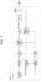
- FIG. 1 is a diagram illustrating an example of functional blocks of a drive device for a rotary electric machine according to a first embodiment of the present invention.
- FIG. 1 only the minimum necessary functional blocks are illustrated in the first embodiment, and a power conversion unit including a driving transistor such as an insulated-gate bipolar transistor (IGBT) and a power device such as a diode and a control configuration for the power conversion unit are illustrated in a block diagram as a voltage output device 3, and detailed illustration is omitted.
- a driving transistor such as an insulated-gate bipolar transistor (IGBT)
- a power device such as a diode and a control configuration for the power conversion unit
- the rotary electric machine is used as the synchronous machine 4 in FIG. 1
- an induction machine other than the synchronous machine may be used as illustrated in FIGS. 18 to 20 to be described later.
- the voltage output device 3 applies a three-phase AC voltage to the synchronous machine 4 via a drive circuit and a main circuit (not illustrated, but included in the voltage output device 3) based on a switching command from a control device 2.
- a current detector 5 includes a Hall current transformer (CT) or the like, and detects waveforms of three-phase currents i u , i v , and i w of a U phase, a V phase, and a W phase flowing through the synchronous machine 4.
- CT Hall current transformer
- a control program for driving and controlling the synchronous machine 4 connected as a load is implemented in the control device 2.
- the control device 2 A control program for driving and controlling the synchronous machine 4 connected as a load is implemented in the control device 2.
- a functional aspect of each component included in the control device 2 will be described.
- a torque command calculation unit 11 outputs a torque command value ⁇ m * in accordance with an operation command from a host device.
- a current command calculation unit 10 outputs dq-axis current command values i d * and i q * for obtaining a predetermined torque to the torque command value ⁇ m *.
- a current detection coordinate conversion unit 8 converts the three-phase currents i u , i v , and i w of the synchronous machine 4 detected by the current detector 5 into dq coordinates of a rotating coordinate system by using a d-axis estimation phase ⁇ dc recognized by the control device 2, and outputs, as dq-axis current detection values (i df and i qf ), the dq coordinates to the current control unit 9.
- the current control unit 9 generates and outputs dq voltage command values v d * and v q * by proportional integral (PI) control or the like such that a current deviation between the dq-axis current detection value output from the current detection coordinate conversion unit 8 and a dq-axis current command value output from the current command calculation unit 10 becomes zero.
- PI proportional integral
- the voltage command coordinate conversion unit 12 outputs three-phase AC voltage command values v u *, v v *, and v w * by using the dq-axis voltage command value output from the current control unit 9 and the d-axis estimation phase ⁇ dc .
- a PWM control unit 7 outputs a switching command of a pulse width modulation (PWM voltage) to the voltage output device 3 based on the three-phase AC voltage command values vu*, vv*, and vw* output from the voltage command coordinate conversion unit 12.
- PWM voltage pulse width modulation
- a phase synchronization control unit 14 outputs an angular velocity estimation value ⁇ 1 ⁇ to set phase deviation information ⁇ c to be zero based on phase deviation information ⁇ c .
- an acceleration and deceleration phase deviation compensation amount ⁇ ⁇ is output.
- the phase deviation information ⁇ c indicates a difference between a phase estimation value ⁇ dc and a rotor phase ⁇ d of the synchronous machine 4.
- the phase deviation information ⁇ c may be either an estimation value ⁇ est of a phase deviation by sensorless control or phase deviation information ⁇ c obtained by calculating a difference from the phase estimation value ⁇ dc by using information on the phase detection value ⁇ r by a resolver or the like although not illustrated.
- a method for estimating the phase deviation estimation value based on a radio-frequency current detection value when a radio-frequency voltage is superimposed in a low speed range or a method for estimating the phase deviation estimation value by using an induced voltage of a rotary electric machine in a high speed range is used as a method for obtaining the phase deviation estimation value ⁇ est .
- a slip/slide detection determination unit 15 performs detection determination of slip and slide based on the acceleration and deceleration phase deviation compensation amount ⁇ ⁇ output from the phase synchronization control unit 14, and outputs a slip/slide detection signal to the torque command calculation unit 11.
- the torque command calculation unit 11 quickly narrows the torque command value ⁇ m * to converge the slip/slide generated between a wheel which is a drive wheel and a rail, and causes the wheel re-adhere to the rail.
- a phase calculation unit 13 performs integration processing on the angular velocity estimation value ⁇ 1 ⁇ output from the phase synchronization control unit 14 and outputs the phase estimation value ⁇ dc .
- FIG. 2 is a diagram illustrating a schematic configuration of a carriage for the railway vehicle.
- the synchronous machine 4 is provided in the carriage 31, and a rotor shaft 30 of the synchronous machine 4 transmits power to a small gear 32 via a joint 34.
- An axle 35 is rotated by a reduction gear including the small gear 32 and a large gear 33, and a wheel 27 connected to the axle 35 is rotated.
- the wheel 27 transmits force to the carriage 31 to accelerate a vehicle by a tangential force generated on the wheel 27 as a reaction force received by a wheel tread surface from the rail 36.
- FIG. 3 is a diagram illustrating functional blocks of a motion equation of a vehicle and one drive wheel axle.
- a motion equation of a vehicle body and a motor is illustrated in a block diagram in consideration of adhesion due to a tangential force coefficient ⁇ between the wheel which is the drive wheel and the rail by motor torque.
- Force that rotates the wheel is determined by a difference between a wheel torque and a tangential force torque
- force that accelerates the vehicle is determined by a difference between tangential force and travel resistance, and these forces change depending on the tangential force coefficient ⁇ .
- FIG. 4 is a diagram illustrating a relationship between a slip speed between the wheel and the rail and the tangential force coefficient ⁇ .
- the tangential force coefficient ⁇ changes depending on the slip speed that is a difference between a wheel peripheral speed and a vehicle body speed.
- the tangential force coefficient ⁇ is lower than that in fine weather, and the slip/slide is likely to occur.
- the tangential force coefficient ⁇ changes not only due to rain but also due to oil, fallen leaves, and dust on a rail surface, and also due to a vehicle speed.
- FIG. 5 is a diagram illustrating the slip/slide during powering and regeneration of the railway vehicle.
- FIG. 6 is a diagram illustrating the phase deviation generated while the vehicle is being accelerated and decelerated.
- phase deviation ⁇ is defined as a deviation between the rotor phase ⁇ d of the synchronous machine 4 and the control phase estimation value ⁇ dc by the following equation (Math. 1).
- s is a Laplace operator
- ⁇ r is a rotor angular velocity of the synchronous machine 4.
- phase synchronization control unit 14 is constructed by general PI control
- a proportional gain and an integral gain in the phase synchronization control unit 14 are K P and K I , respectively
- the angular velocity estimation value ⁇ 1 ⁇ can be calculated by the following equation (Math. 2) based on the phase deviation information ⁇ c .
- ⁇ 1 ⁇ K P + K I s ⁇ ⁇ ⁇ c
- the rotor angular velocity ⁇ r of the synchronous machine 4 can be calculated from a motor torque ⁇ m and an inertia moment J by the following equation (Math. 3).
- P m is the number of pole pairs of the synchronous machine 4.
- the inertia moment J is treated as an equivalent inertia moment obtained by combining up to adhesion due to a vehicle mass and the tangential force coefficient ⁇ as viewed from the motor axis illustrated in FIG. 3 for simplification of description.
- phase deviation ⁇ K P + K I s ⁇ ⁇ ⁇ c ⁇ ⁇ m ⁇ P m J ⁇ s ⁇ 1 s
- FIG. 7 is a diagram illustrating a current vector in a case where the phase deviation ⁇ occurs between the rotor phase ( ⁇ d ) and the control phase estimation value ( ⁇ dc ).
- a reference phase of a rotor of the synchronous machine 4 is set as a d-axis
- a reference phase of the rotor estimated by the control device 2 is set as a dc-axis, and the phase deviation ⁇ occurs
- current control is performed to obtain the current command values i d * and i q *, but actually flowing currents are i d and i q , and the torque ⁇ m actually output by the motor has a large error with respect to the torque command value ⁇ m *.
- phase deviation ⁇ corresponding to the acceleration not only in a state where a speed changes at a high acceleration such as during the slip/slide but also during normal acceleration and deceleration in an adhesion state.
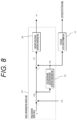
- FIG. 8 is a diagram illustrating an example of functional blocks of the phase synchronization control unit 14 according to the first embodiment.
- the phase synchronization control unit 14 includes a constant speed phase deviation converging unit 20 that can converge the phase deviation to zero at a constant speed and an acceleration and deceleration phase deviation converging unit 21 that can converge the phase deviation at the time of the acceleration and deceleration.
- the acceleration and deceleration phase deviation converging unit 21 receives, as an input, a phase deviation amount (before compensation) ⁇ c0 which is a difference between the phase deviation information ⁇ c and a phase deviation target value, and outputs the acceleration and deceleration phase deviation compensation amount ⁇ ⁇ .
- the constant speed phase deviation converging unit 20 receives, as an input, a phase deviation amount (after compensation) ⁇ c ' that is an addition value of the phase deviation amount (before compensation) ⁇ c0 and the acceleration and deceleration phase deviation compensation amount ⁇ ⁇ , and outputs the angular velocity estimation value ⁇ 1 ⁇ .
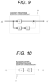
- FIG. 9 is a diagram illustrating an example of functional blocks of the constant speed phase deviation converging unit 20.
- the PI control using the proportional gain K P and the integral gain K I is performed.
- FIG. 10 is a diagram illustrating an example of functional blocks of the acceleration and deceleration phase deviation converging unit 21.
- the integration is performed by an integral gain K II .
- an order of a transfer function for calculating the angular velocity estimation value ⁇ 1 ⁇ from the phase deviation ⁇ c in the phase synchronization control unit 14 may be constructed to be second or higher as illustrated in the following equation (Math. 7).
- ⁇ 1 ′ K P + K I s 1 + K II s ⁇ ⁇ c
- the acceleration and deceleration phase deviation converging unit 21 operates to output a compensation amount such that the steady-state deviation of the phase deviation ⁇ with K II /s of (Math. 6) becomes zero, the output (acceleration and deceleration phase deviation compensation amount) ⁇ ⁇ has a relationship of the following equation (Math. 10).
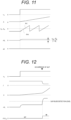
- FIG. 11 is a diagram illustrating an example of an effect obtained by adding compensation by the acceleration and deceleration phase deviation converging unit 21.
- the steady-state deviation of the phase at the time of the acceleration and deceleration can be converged to zero by the acceleration and deceleration phase deviation compensation amount ⁇ ⁇ which is the output of the acceleration and deceleration phase deviation converging unit 21. Even in a case where the slip/slide occurs and the acceleration and deceleration increase, it is possible to prevent an increase in the phase deviation and to prevent control instability and a decrease in torque accuracy.
- the acceleration and deceleration phase deviation compensation amount ⁇ ⁇ which is the output of the acceleration and deceleration phase deviation converging unit 21 changes depending on the equivalent inertia moment J including the vehicle mass and the tangential force coefficient ⁇ as viewed from the motor axis in a case where the torque ⁇ m and the integral gain K I are known.
- the inventors have found that information corresponding to acceleration can be obtained from phase deviation information without using differential processing by focusing on the acceleration and deceleration phase deviation compensation amount ⁇ ⁇ which is the output of the acceleration and deceleration phase deviation converging unit 21, and have devised a method for detecting the slip/slide based on this information.
- FIG. 12 is a diagram illustrating a method for detecting the slip by the output of the acceleration and deceleration phase deviation converging unit when the slip occurs.
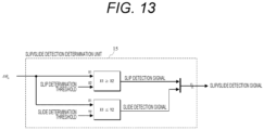
- FIG. 13 is a diagram illustrating an example of functional blocks of the slip/slide detection determination unit 15.
- the slip/slide is regarded as occurring, and the slip/slide detection signal is output to the torque command calculation unit 11.
- the slip determination threshold or the slide determination threshold is set to a level that is larger than the compensation amount at the time of the acceleration and deceleration in the adhesion state and does not cause erroneous detection depending on a vibration component included in the phase deviation information.
- FIG. 14 is a diagram illustrating a comparison between a configuration of the related art for detecting the slip/slide and a configuration of the present invention.
- phase synchronization control unit 16 of the related art since the phase synchronization control unit 16 of the related art has a cutoff frequency, a problem that the detection of the slip/slide is delayed cannot be avoided. Furthermore, in a case where differential processing is used to calculate an acceleration, it is necessary to provide low-pass filter processing as described in PTL 1 and PTL 2 as a countermeasure against noise, and it is obvious that the detection of the slip/slide is delayed.
- the acceleration component of the phase deviation estimation value ⁇ est before the frequency estimation value is calculated is extracted to detect the slip/slide.
- the slip/slide can be detected earlier than in the configuration of the related art.
- phase deviation ⁇ represented in (Math. 6) is suppressed even in the adhesion state in which the slip/slide does not occur, the effect of stabilizing the sensorless control and improving torque accuracy can also be obtained without causing a torque error due to the phase deviation described with reference to FIG. 7 .
- FIG. 15 is a diagram illustrating an example of functional blocks of a phase synchronization control unit 14a according to a modification of the first embodiment
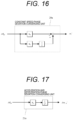
- FIG. 16 is a diagram illustrating an example of functional blocks of a constant speed phase deviation converging unit 20a in the phase synchronization control unit 14a
- FIG. 17 is a diagram illustrating an example of functional blocks of an acceleration and deceleration phase deviation converging unit 21a in the phase synchronization control unit 14a.
- the phase synchronization control unit 14a is different from the phase synchronization control unit 14 illustrated in FIG. 8 in that a phase deviation amount (before compensation) ⁇ c0 is input in parallel to the constant speed phase deviation converging unit 20a and the acceleration and deceleration phase deviation converging unit 21a.
- the acceleration and deceleration phase deviation converging unit 21a sets an order of a denominator of a transfer function for calculating the angular velocity estimation value ⁇ 1 ⁇ from the phase deviation ⁇ c by providing a square term of 1/s as illustrated in FIG. 17 .
- an effect of suppressing the phase deviation ⁇ at the time of the acceleration and deceleration can be obtained.
- the order may be any order as long as a term of the second or higher order is included, and the phase synchronization control unit 14 is not necessarily limited to the configuration illustrated in FIGS. 8 to 10 or FIGS. 15 to 17 .
- phase synchronization control unit 14 is constructed by calculating the difference from the phase estimation value ⁇ dc by using the information on the phase detection value ⁇ r by the resolver or the like and using the difference as the phase deviation information ⁇ c , since the steady-state deviation similarly remains while the vehicle is being accelerated and decelerated, the present invention can also be applied to a configuration of control with a resolver or control with a speed sensor.
- the synchronous machine 4 has been described as an example of the rotary electric machine, but the rotary electric machine is not limited to the synchronous machine, and can be applied to other rotary electric machines such as an induction machine.
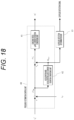
- FIG. 18 is a diagram illustrating an example of functional blocks of a frequency estimation control unit 40 in a case where the first embodiment is applied to the drive device of the induction machine
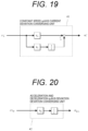
- FIG. 19 is a diagram illustrating an example of functional blocks of a constant speed q-axis current deviation converging unit 41 in a frequency estimation control unit 40
- FIG. 20 is a diagram illustrating an example of functional blocks of an acceleration and deceleration q-axis current deviation converging unit 42 in the frequency estimation control unit 40.
- the acceleration and deceleration q-axis current deviation converging unit 42 compensates for a q-axis current deviation amount due to the acceleration. That is, when the slip/slide is detected based on an acceleration and deceleration q-axis current deviation compensation amount ⁇ i q_ ⁇ which is an output of the acceleration and deceleration q-axis current deviation converging unit 42, it is possible to obtain an effect of detecting the slip/slide in an early stage while speed estimation control is stabilized.
- the effect of the present invention can be obtained by a configuration in which a compensation value for correcting a quantity of a state (an estimation phase of the rotor in the case of the synchronous machine or a current flowing through the induction machine in the case of the induction machine) to be used as an input of the calculation of the angular velocity estimation value is output in order to suppress a deviation amount generated in the quantity of the state while the rotary electric machine is being accelerated and decelerated to be substantially zero and the slip/slide is detected in a case where the compensation value exceeds a predetermined value.
- the drive device for the rotary electric machine includes the voltage output device 3 that outputs the voltage to the synchronous machine 4 and the control device 2 that controls the output voltage of the voltage output device 3 based on the torque command value ⁇ m *, and the control device 2 includes the phase synchronization control unit 14 that outputs the angular velocity estimation value ⁇ 1 ⁇ from the phase deviation information of the rotor.
- the phase synchronization control unit 14 includes the acceleration and deceleration phase deviation converging unit 21 that suppresses the steady-state deviation of the estimation phase at the time of the acceleration and deceleration, and includes the slip/slide detection determination unit 15 that detects a slip/slide state of the wheel driven by the synchronous machine 4 based on the output of the acceleration and deceleration phase deviation converging unit 21.
- the slip/slide detection determination unit 15 that detects a slip/slide state of the wheel driven by the synchronous machine 4 based on the output of the acceleration and deceleration phase deviation converging unit 21.
- a second embodiment according to the present invention is different from the first embodiment in that a determination threshold for detecting the slip/slide by the slip/slide detection determination unit 15 is set to be variable depending on an operating state of the vehicle and a surrounding environment.
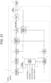
- FIG. 21 is a diagram illustrating an example of functional blocks of a drive device for a rotary electric machine according to a second embodiment.
- the torque command value ⁇ m *, occupancy rate information, weather information, in-composition positional information, and the angular velocity estimation value ⁇ 1 ⁇ are input to the slip/slide detection determination unit 15, and the slip/slide determination threshold is set to be variable.
- FIG. 22 is a diagram illustrating an example of functional blocks of the slip/slide detection determination unit 15 according to the second embodiment.
- the determination threshold is adjusted to be high in a case where the torque command value ⁇ m * becomes large and the determination threshold is adjusted to be low in a case where the torque command value ⁇ m * becomes small.
- it is also possible to set an appropriate determination threshold for the state of the torque and it is possible to realize higher speed detection while the erroneous detection of the slip/slide is prevented.
- a value obtained by dividing the torque command value ⁇ m * by the integral gain K I and the inertia moment J is set as the slip/slide determination threshold according to a calculation expression of (Math. 10).
- the occupancy rate information is calculated as the equivalent inertia moment J by the equivalent inertia moment calculation unit 50.
- the determination threshold is lowered.
- a weather information correction gain calculation unit 51 having weather information as an input calculates a weather information correction gain and outputs the calculated gain as one of correction gains of the slip/slide determination threshold.
- an in-composition positional information correction gain calculation unit 52 having the in-composition positional information as an input calculates an in-composition positional information correction gain and outputs the calculated gain as one of the correction gains of the slip/slide determination threshold.
- the tangential force coefficient ⁇ has dependency on the vehicle speed (see tangential force coefficient table illustrated in FIG. 3 ), and the tangential force coefficient ⁇ decreases as the vehicle speed increases.
- the traveling resistance also increases as the speed increases, and the slip/slide of the wheel easily occurs.
- the determination threshold is lowered.
- the determination threshold is decreased.
- a frequency of the rotary electric machine or the vehicle speed may be directly used. By doing this, it is possible to set an appropriate determination threshold corresponding to the vehicle speed, and it is possible to realize further high-speed detection while the erroneous detection of the slip/slide is prevented.
- a speed correction gain calculation unit 53 having the angular velocity estimation value ⁇ 1 ⁇ as an input calculates a traveling resistance correction gain and outputs the calculated gain as one of the correction gains of the slip/slide determination threshold.
- adjustment means of the determination thresholds may be any method as long as the slip/slide determination threshold is changed depending on each parameter such as a calculation expression or a table for each parameter.
- the torque command value ⁇ m *, the occupancy rate information, the weather information, the in-composition positional information, and the angular velocity estimation value ⁇ 1 ⁇ are taken into the slip/slide detection determination unit 15, and the determination threshold for detecting the slip/slide is set to be variable depending on these pieces of information. As a result, it is possible to realize further high-speed slip/slide detection while the erroneous detection of the slip/slide is prevented.
- a third embodiment according to the present invention is different from the second embodiment in that an upper and lower limiter is provided for the output of the acceleration and deceleration phase deviation converging unit 21.
- phase deviation information ⁇ c rapidly vibrates, and the output ⁇ ⁇ of the acceleration and deceleration phase deviation converging unit 21 becomes excessive, an effect of stabilizing the control system can be obtained without deteriorating followability of the phase synchronization control unit 14.
- FIG. 23 is a diagram illustrating an example of functional blocks of a drive device for a rotary electric machine according to the third embodiment.
- the slip/slide determination threshold is output from the slip/slide detection determination unit 15, is input to the phase synchronization control 14, and is used for calculating upper and lower limit values for the output of the acceleration and deceleration phase deviation converging unit 21.
- FIG. 24 is a diagram illustrating an example of functional blocks of the slip/slide detection determination unit 15 according to the third embodiment.
- a function of outputting the determination threshold for detecting the slip/slide is added to the slip/slide detection determination unit 15 according to the second embodiment illustrated in FIG. 22 .
- FIG. 25 is a diagram illustrating an example of functional blocks of the acceleration and deceleration phase deviation converging unit 21 according to the third embodiment.
- an upper and lower limiter 22 is provided at the output of the acceleration and deceleration phase deviation compensation amount ⁇ ⁇ .
- a set value of the upper and lower limiter 22 is set to a value slightly larger than a level determined as the slip detection by multiplying the slip/slide determination threshold by a determination threshold adjustment gain.
- an upper limit value of the upper and lower limiter 22 is set based on the determination threshold at the time of the slip, and a lower limit value of the upper and lower limiter 22 is set based on the determination threshold at the time of the slide.
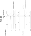
- FIG. 26 is a diagram illustrating a comparison of effects depending on the presence or absence of the upper and lower limiter 22 provided in the acceleration and deceleration phase deviation converging unit 21.
- the acceleration and deceleration phase deviation compensation amount ⁇ ⁇ continues to accumulate until the slip converges after the slip is detected and the narrowing of the torque is started. Thus, it takes time for the acceleration and deceleration phase deviation compensation amount ⁇ ⁇ to return to a steady-state value even after re-adhesion.
- the limiter in a case where the limiter is limited to a value slightly larger than a slip/slide detection level, it is possible to prevent the acceleration and deceleration phase deviation compensation amount ⁇ ⁇ from being excessively exceeded and to obtain an effect of accelerating the convergence of the acceleration and deceleration phase deviation compensation amount ⁇ ⁇ after re-adhesion to the steady-state value.
- the upper and lower limiter 22 is provided in the output of the acceleration and deceleration phase deviation converging unit 21, and thus, the convergence of the acceleration and deceleration phase deviation compensation amount ⁇ ⁇ to the steady-state value is accelerated after the re-adhesion control by a torque operation. As a result, it is possible to prevent the erroneous detection of the slip/slide after the re-adhesion.
Landscapes
- Engineering & Computer Science (AREA)
- Power Engineering (AREA)
- Transportation (AREA)
- Mechanical Engineering (AREA)
- Life Sciences & Earth Sciences (AREA)
- Sustainable Development (AREA)
- Sustainable Energy (AREA)
- Control Of Ac Motors In General (AREA)
- Electric Propulsion And Braking For Vehicles (AREA)
- Control Of Electric Motors In General (AREA)
Applications Claiming Priority (2)
| Application Number | Priority Date | Filing Date | Title |
|---|---|---|---|
| JP2020201959 | 2020-12-04 | ||
| PCT/JP2021/043765 WO2022118822A1 (ja) | 2020-12-04 | 2021-11-30 | 回転電機の駆動装置、駆動方法および鉄道車両 |
Publications (4)
| Publication Number | Publication Date |
|---|---|
| EP4258540A1 true EP4258540A1 (de) | 2023-10-11 |
| EP4258540A4 EP4258540A4 (de) | 2024-10-23 |
| EP4258540B1 EP4258540B1 (de) | 2026-03-04 |
| EP4258540C0 EP4258540C0 (de) | 2026-03-04 |
Family
ID=81853196
Family Applications (1)
| Application Number | Title | Priority Date | Filing Date |
|---|---|---|---|
| EP21900575.8A Active EP4258540B1 (de) | 2020-12-04 | 2021-11-30 | Antriebsvorrichtung und antriebsverfahren für elektrische drehmaschine und schienenfahrzeug |
Country Status (4)
| Country | Link |
|---|---|
| EP (1) | EP4258540B1 (de) |
| JP (3) | JP7506764B2 (de) |
| CN (1) | CN116547164A (de) |
| WO (1) | WO2022118822A1 (de) |
Families Citing this family (2)
| Publication number | Priority date | Publication date | Assignee | Title |
|---|---|---|---|---|
| CN115716414B (zh) * | 2022-11-28 | 2024-12-27 | 长沙普洛电气设备有限公司 | 一种轨道车辆车轮矢量同步控制方法以及系统 |
| CN119840444B (zh) * | 2025-03-19 | 2025-06-10 | 江苏倍斯特物联网技术有限公司 | 基于risc-v架构的新能源电车储能实时控制方法及装置 |
Family Cites Families (8)
| Publication number | Priority date | Publication date | Assignee | Title |
|---|---|---|---|---|
| WO1999015355A1 (fr) * | 1997-09-24 | 1999-04-01 | Hitachi, Ltd. | Regulateur de vehicule electrique |
| JP3890200B2 (ja) | 2001-03-19 | 2007-03-07 | 財団法人鉄道総合技術研究所 | 電動機制御装置及び電動機制御方法 |
| JP5515885B2 (ja) * | 2010-03-12 | 2014-06-11 | 富士電機株式会社 | 電気車制御装置 |
| JP5908205B2 (ja) * | 2010-11-30 | 2016-04-26 | 株式会社東芝 | 回転センサレス制御装置 |
| US9020731B2 (en) * | 2011-04-05 | 2015-04-28 | Toyota Jidosha Kabushiki Kaisha | Control apparatus for electric motor, electrically-powered vehicle including the control apparatus, and method for controlling electric motor |
| EP2982538A4 (de) * | 2013-04-01 | 2017-03-08 | Pioneer Corporation | Antriebsregelungsvorrichtung und antriebsregelungsverfahren |
| US9463697B1 (en) * | 2015-05-28 | 2016-10-11 | Atieva, Inc. | Dual data rate traction control system for a two wheel drive electric vehicle |
| EP3680123B1 (de) * | 2019-01-09 | 2024-11-20 | ALSTOM Holdings | Verfahren zur steuerung eines schienenfahrzeuges, steuergerät und schienenfahrzeug |
-
2021
- 2021-11-30 EP EP21900575.8A patent/EP4258540B1/de active Active
- 2021-11-30 JP JP2022566924A patent/JP7506764B2/ja active Active
- 2021-11-30 WO PCT/JP2021/043765 patent/WO2022118822A1/ja not_active Ceased
- 2021-11-30 CN CN202180081292.4A patent/CN116547164A/zh active Pending
-
2024
- 2024-06-13 JP JP2024096152A patent/JP7755691B2/ja active Active
-
2025
- 2025-08-28 JP JP2025142123A patent/JP2025161987A/ja active Pending
Also Published As
| Publication number | Publication date |
|---|---|
| EP4258540B1 (de) | 2026-03-04 |
| JP7506764B2 (ja) | 2024-06-26 |
| EP4258540C0 (de) | 2026-03-04 |
| EP4258540A4 (de) | 2024-10-23 |
| JPWO2022118822A1 (de) | 2022-06-09 |
| CN116547164A (zh) | 2023-08-04 |
| JP2024107419A (ja) | 2024-08-08 |
| WO2022118822A1 (ja) | 2022-06-09 |
| JP2025161987A (ja) | 2025-10-24 |
| JP7755691B2 (ja) | 2025-10-16 |
Similar Documents
| Publication | Publication Date | Title |
|---|---|---|
| EP2642658B1 (de) | Steuerung für einen Elektromotor | |
| CA2660601C (en) | Vector control device for alternating-current electric motor | |
| JP7755691B2 (ja) | 回転電機の駆動装置、駆動方法および鉄道車両 | |
| CN108736786B (zh) | 电动机的控制装置 | |
| EP3985862A1 (de) | Vorrichtung und verfahren zur ansteuerung eines permanentmagnetsynchronmotors und schienenfahrzeug | |
| JP5515885B2 (ja) | 電気車制御装置 | |
| JPWO2005110802A1 (ja) | 電気車制御装置 | |
| US20260019020A1 (en) | Synchronous Machine Control Device, Synchronous Machine Control Method, and Electric Vehicle | |
| JP4903740B2 (ja) | 電動機制御方法及び電動機制御装置 | |
| JP2008086085A (ja) | 電気車制御装置 | |
| JPWO2022118822A5 (de) | ||
| JP3817666B2 (ja) | 誘導電動機の駆動制御装置 | |
| KR20090004375A (ko) | 전기차의 전력 변환 장치 | |
| JP6017842B2 (ja) | 再粘着制御方法及び電動機制御装置 | |
| JP2012114974A (ja) | 電気車制御装置 | |
| JP4131785B2 (ja) | 電気車の駆動制御装置及び空転制御方法 | |
| JP2000253506A (ja) | 速度センサレス制御を用いた電気車制御装置 | |
| EP4566865A1 (de) | Fahrzeugsteuerungsvorrichtung, fahrzeugsteuerungsverfahren und fahrzeugsteuerungssystem | |
| JP4120503B2 (ja) | 誘導電動機の制御方法 | |
| US20250183827A1 (en) | Motor control device and electric vehicle | |
| JP2002044804A (ja) | 電動機制御装置および再粘着制御方法 | |
| JP4675264B2 (ja) | ロータ周波数推定装置及びロータ周波数推定方法 | |
| JP6990112B2 (ja) | 再粘着制御方法および電動機制御装置 | |
| CN121175213A (zh) | 铁道车辆用驱动装置及其控制方法 | |
| CN119452563A (zh) | 交流电动机控制装置及电动车、交流电动机控制方法 |
Legal Events
| Date | Code | Title | Description |
|---|---|---|---|
| STAA | Information on the status of an ep patent application or granted ep patent |
Free format text: STATUS: THE INTERNATIONAL PUBLICATION HAS BEEN MADE |
|
| PUAI | Public reference made under article 153(3) epc to a published international application that has entered the european phase |
Free format text: ORIGINAL CODE: 0009012 |
|
| STAA | Information on the status of an ep patent application or granted ep patent |
Free format text: STATUS: REQUEST FOR EXAMINATION WAS MADE |
|
| 17P | Request for examination filed |
Effective date: 20230524 |
|
| AK | Designated contracting states |
Kind code of ref document: A1 Designated state(s): AL AT BE BG CH CY CZ DE DK EE ES FI FR GB GR HR HU IE IS IT LI LT LU LV MC MK MT NL NO PL PT RO RS SE SI SK SM TR |
|
| DAV | Request for validation of the european patent (deleted) | ||
| DAX | Request for extension of the european patent (deleted) | ||
| A4 | Supplementary search report drawn up and despatched |
Effective date: 20240919 |
|
| RIC1 | Information provided on ipc code assigned before grant |
Ipc: H02P 21/18 20160101ALI20240913BHEP Ipc: B60L 15/02 20060101ALI20240913BHEP Ipc: B60L 15/38 20060101ALI20240913BHEP Ipc: B60L 3/12 20060101ALI20240913BHEP Ipc: B60L 3/10 20060101ALI20240913BHEP Ipc: B60L 15/20 20060101ALI20240913BHEP Ipc: H02P 29/024 20160101AFI20240913BHEP |
|
| STAA | Information on the status of an ep patent application or granted ep patent |
Free format text: STATUS: EXAMINATION IS IN PROGRESS |
|
| 17Q | First examination report despatched |
Effective date: 20250429 |
|
| GRAP | Despatch of communication of intention to grant a patent |
Free format text: ORIGINAL CODE: EPIDOSNIGR1 |
|
| STAA | Information on the status of an ep patent application or granted ep patent |
Free format text: STATUS: GRANT OF PATENT IS INTENDED |
|
| INTG | Intention to grant announced |
Effective date: 20251014 |
|
| GRAS | Grant fee paid |
Free format text: ORIGINAL CODE: EPIDOSNIGR3 |
|
| GRAA | (expected) grant |
Free format text: ORIGINAL CODE: 0009210 |
|
| STAA | Information on the status of an ep patent application or granted ep patent |
Free format text: STATUS: THE PATENT HAS BEEN GRANTED |
|
| AK | Designated contracting states |
Kind code of ref document: B1 Designated state(s): AL AT BE BG CH CY CZ DE DK EE ES FI FR GB GR HR HU IE IS IT LI LT LU LV MC MK MT NL NO PL PT RO RS SE SI SK SM TR |
|
| REG | Reference to a national code |
Ref country code: CH Ref legal event code: F10 Free format text: ST27 STATUS EVENT CODE: U-0-0-F10-F00 (AS PROVIDED BY THE NATIONAL OFFICE) Effective date: 20260304 Ref country code: GB Ref legal event code: FG4D |
|
| REG | Reference to a national code |
Ref country code: DE Ref legal event code: R096 Ref document number: 602021049487 Country of ref document: DE |
|
| REG | Reference to a national code |
Ref country code: IE Ref legal event code: FG4D |
|
| U01 | Request for unitary effect filed |
Effective date: 20260318 |